WO2024070976A1 - 血管穿刺装置 - Google Patents
血管穿刺装置 Download PDFInfo
- Publication number
- WO2024070976A1 WO2024070976A1 PCT/JP2023/034583 JP2023034583W WO2024070976A1 WO 2024070976 A1 WO2024070976 A1 WO 2024070976A1 JP 2023034583 W JP2023034583 W JP 2023034583W WO 2024070976 A1 WO2024070976 A1 WO 2024070976A1
- Authority
- WO
- WIPO (PCT)
- Prior art keywords
- puncture device
- puncture
- backflow
- blood vessel
- blood
- Prior art date
- Legal status (The legal status is an assumption and is not a legal conclusion. Google has not performed a legal analysis and makes no representation as to the accuracy of the status listed.)
- Ceased
Links
Images




Classifications
-
- A—HUMAN NECESSITIES
- A61—MEDICAL OR VETERINARY SCIENCE; HYGIENE
- A61B—DIAGNOSIS; SURGERY; IDENTIFICATION
- A61B17/00—Surgical instruments, devices or methods
- A61B17/34—Trocars; Puncturing needles
- A61B17/3403—Needle locating or guiding means
-
- A—HUMAN NECESSITIES
- A61—MEDICAL OR VETERINARY SCIENCE; HYGIENE
- A61B—DIAGNOSIS; SURGERY; IDENTIFICATION
- A61B8/00—Diagnosis using ultrasonic, sonic or infrasonic waves
- A61B8/13—Tomography
- A61B8/14—Echo-tomography
-
- A—HUMAN NECESSITIES
- A61—MEDICAL OR VETERINARY SCIENCE; HYGIENE
- A61B—DIAGNOSIS; SURGERY; IDENTIFICATION
- A61B17/00—Surgical instruments, devices or methods
- A61B17/34—Trocars; Puncturing needles
- A61B17/3403—Needle locating or guiding means
- A61B2017/3413—Needle locating or guiding means guided by ultrasound
Definitions
- the present invention relates to a vascular puncture device that punctures a blood vessel with a needle.
- Vascular puncture is performed by inserting an injection needle into the human body to secure an access site for drug administration or intravascular treatment.
- the surgeon cannot see the blood vessel from the surface of the skin, so they estimate the location of the blood vessel using standard knowledge of the course of blood vessels and skills such as palpation of blood vessel pulsation.
- puncturing a blood vessel often fails, causing physical and mental distress to the patient.
- the present invention has been made to solve the above-mentioned problems, and aims to provide a vascular puncture device that controls the puncture device based on information about backflow blood.
- the blood vessel puncture device of the present invention which achieves the above-mentioned objective, is a blood vessel puncture device that punctures a living body using a puncture device, and includes a puncture drive unit that punctures the living body with the puncture device, a backflow blood detection unit that detects backflow blood flowing from a blood vessel into the puncture device, and a control unit that drives the puncture drive unit to control the position of the puncture device based on information about the backflow blood detected by the backflow blood detection unit.
- the blood vessel puncture device configured as described above controls the position of the puncture device based on information about backflow blood that occurs when the puncture device punctures the blood vessel, so the position can be controlled after accurately understanding the state of puncture of the blood vessel by the puncture device, allowing for precise puncture.
- FIG. 2 is a front view of the vascular puncture device of the present embodiment.
- FIG. 4 is a perspective view showing the internal structure of the puncture drive unit.
- FIG. 1 is a diagram showing the configuration of a blood vessel puncture device.
- FIG. 2 is a diagram showing the skin contact surface of the probe body, illustrating its positional relationship with the arm from which a cross-sectional image is acquired.
- 1 is a flowchart showing a puncture process using a vascular puncture device.
- FIG. 2 is a conceptual diagram of an acquired echo image.
- 4 is a cross-sectional view showing the positional relationship between a blood vessel and an imaging unit.
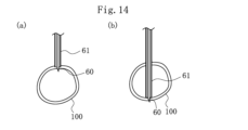
- FIG. FIG. 13 is a diagram showing the relationship between the inner needle and the blood vessel during insertion.
- 13 is a flowchart according to a first modified example of puncturing using a blood vessel puncture device.
- 13 is a flowchart according to a second modified example of puncturing using the blood vessel puncture device.
- 13 is a graph showing the relationship between the expected amount of backflow blood and the insertion depth of the puncture device.
- 1 is a diagram showing the relationship between a puncture device having an outer cylinder and a blood vessel.
- 13 is a flowchart according to a third modified example of puncturing using a blood vessel puncture device.
- FIG. 13 is a flowchart according to a fourth modified example of puncturing using a blood vessel puncture device.
- FIG. 2 is a front view of a guidewire driving device attached to the puncture driving unit.
- FIG. 13 is a front view of a blood vessel puncture device according to a modified example.
- the vascular puncture device 10 is used to puncture the arm of a human body, acquiring cross-sectional images of the arm to detect the position of the blood vessel, determining the puncture timing and puncture parameters, and inserting the needle into the blood vessel.
- the vascular puncture device 10 has a probe body 20 with an imaging unit 22 that contacts the skin surface to obtain cross-sectional images of the human body, and a puncture drive unit 21 that holds a puncture device 41 and drives it to perform puncture.
- the puncture drive unit 21 has a fixing unit 21a that engages and is fixed to the probe body 20, and the probe body 20 and the puncture drive unit 21 are integrated.
- the puncture drive unit 21 has a main body 40 that holds a puncture device 41.
- the main body 40 has a notification unit 23 for notifying the surgeon of the puncture status, etc.
- the notification unit 23 can be configured with a display that displays information, etc. However, the notification unit 23 may be a simpler display unit such as an LED. The notification unit 23 may also notify by voice.
- the puncture device 41 has a hollow needle-shaped inner needle 60 that is inserted into a blood vessel, and a hub 62 that is provided on the base end side of the inner needle 60.
- the inner needle 60 is open at its tip and its base end communicates with the inner cavity of the hub 62.
- the hub 62 has an insertion section 62a that protrudes from the main body section 40 at its base end.
- the insertion section 62a communicates with the inner cavity of the hub 62, and allows a guidewire 80 to be inserted.
- the guidewire 80 inserted from the insertion section 62a can be inserted into the tip side of the inner needle 60, passing through the inner cavity of the hub 62 and the inside of the inner needle 60.
- the hub 62 is provided with a backflow detection unit 35 that detects backflow blood flowing from a blood vessel to the base end side of the inner needle 60.
- the backflow detection unit 35 is a sensor that can detect blood flowing through the lumen of the hub 62 from the tip side to the base end side, and can be composed of a camera.
- the backflow detection unit 35 can also be composed of a pressure sensor, proximity sensor, etc., other than a camera.
- the backflow detection unit 35 may also be fixed to the main body 40.
- the puncture drive unit 21 has a horizontal drive unit 56 supported by the main body unit 40, a two-axis drive unit 57 supported by the horizontal drive unit 56, a puncture direction drive unit 54 supported by the two-axis drive unit 57, a puncture direction guide unit 53 supported by the puncture direction drive unit 54, and a puncture direction movement unit 52 supported by the puncture direction guide unit 53 and movable along the puncture direction.
- Figure 2 shows the X-Y-Z directions.
- the X direction corresponds to the width direction of the arm
- the Y direction corresponds to the depth direction of the arm
- the Z direction corresponds to the length direction of the arm.
- the puncture device 41 is fixed to a holder 50 provided on the puncture direction movement unit 52.
- the two-axis drive unit 57 allows the puncture device 41 to change its orientation relative to the XZ plane. This allows the orientation of the puncture device 41 relative to the planar direction of the skin surface to be changed, allowing the puncture device 41 to enter straight into the blood vessel 100.
- the horizontal drive unit 56 allows the puncture device 41 to move in the X direction. This allows the puncture device 41 to move along the planar direction of the skin surface, and be positioned so that the puncture device 41 can enter the blood vessel 100.
- the two-axis drive unit 57 allows the puncture device 41 to change its inclination within the YZ plane. This allows the angle of incidence of the puncture device 41 relative to the skin surface to be changed.
- the vascular puncture device 10 has an imaging unit 22 that contacts the skin surface to obtain cross-sectional images of the human body, and a control unit 30 that detects the blood vessel position from the cross-sectional image and drives the puncture drive unit 21 to control the position of the puncture device 41.
- the control unit 30 is connected to the imaging unit 22 via the transmission unit 32 and reception unit 34, and can cause the imaging unit 22 to obtain cross-sectional images and receive the obtained cross-sectional images.
- the control unit 30 is connected to the backflow blood detection unit 35, and can obtain information on backflow blood detected by the backflow blood detection unit 35.
- the control unit 30 is also connected to a notification unit 23 provided in the main body unit 40, and can cause the notification unit 23 to provide notifications.
- the imaging section 22 of the probe body 20 extends in one direction at the center of the skin contact surface 20a of the probe body 20, spanning almost the entire width.
- the imaging section 22 is an echo device that has a transducer that generates ultrasound waves and obtains cross-sectional images of the inside of the human body by detecting the reflected waves.
- cross-sectional images perpendicular to the axial direction of the blood vessels are obtained, so the imaging section 22 is positioned so that its length is perpendicular to the length of the arm H.
- the control unit 30 acquires a cross-sectional image as shown in Figure 6 from the imaging unit 22 (S1-1).
- the cross-sectional image includes an image of the blood vessel 100.
- the horizontal direction in the cross-sectional image is the X direction
- the vertical direction in the cross-sectional image is the Y direction
- the direction perpendicular to the paper surface of the cross-sectional image is the Z direction.
- the coordinates of the top left point in this cross-sectional image are set as the starting point (0,0,0).
- the control unit 30 detects the position of the blood vessel 100 in the image by performing image analysis on the acquired cross-sectional image (S1-2).
- the control unit 30 detects an area in the image that is recognized as the blood vessel 100, and sets the center of gravity 110 as the position of the blood vessel.
- the imaging unit 22 can detect an area with blood flow using the Doppler method and recognize the area as the blood vessel area.
- the control unit 30 determines the parameters required for puncturing (S1-3).
- the parameters required for puncturing include the puncturing direction in the X-Z plane, the puncturing position, the incidence angle of the puncturing device 41, the insertion depth of the puncturing device 41, and the puncturing speed of the puncturing device 41.
- the puncturing direction in the X-Z plane is determined so that the puncturing device 41 of the puncturing drive unit 21 fixed to the probe body 20 faces the center of gravity position 110 since the center of gravity position 110 of the blood vessel is detected from the cross-sectional image acquired by the imaging unit 22.
- the puncture position is directly below the side surface 20b of the probe body 20.
- puncture parameters Other parameters may be used as the puncture parameters. For example, the puncture start time, the puncture completion time, the puncture acceleration at the start of puncture, and the puncture acceleration at the completion of puncture may be used.
- control unit 30 operates the puncture drive unit 21 in accordance with the puncture parameters to start puncture (S1-4).
- the control unit 30 determines whether the backflow detection unit 35 detects backflow when the puncture drive unit 21 is inserting the puncture device 41 (S1-5). If the backflow detection unit 35 does not detect backflow, the control unit 30 acquires a cross-sectional image with the imaging unit 22 (S1-6) and determines whether the positional relationship between the inner needle 60 and the blood vessel 100 is normal based on the acquired cross-sectional image (S1-7). If the inner needle 60 is pointing toward the blood vessel 100 in the acquired cross-sectional image, as in Figures 8(a) and 8(b), it is determined that the positional relationship between the inner needle 60 and the blood vessel 100 is normal.
- the inner needle 60 is not pointing toward the blood vessel 100, as in Figure 8(c), it is determined that the positional relationship between the inner needle 60 and the blood vessel 100 is not normal. This determination can be made by detecting the tip coordinates of the inner needle 60 and the coordinate range in which the blood vessel 100 exists in the acquired cross-sectional image by image analysis. Additionally, the positional relationship between the inner needle 60 and the blood vessel 100 may be determined using machine learning or deep learning techniques.
- step S1-7 If it is determined in S1-7 that the positional relationship between the inner needle 60 and the blood vessel 100 is normal, the process returns to step S1-5. If it is determined in S1-7 that the positional relationship between the inner needle 60 and the blood vessel 100 is not normal, the control unit 30 stops the insertion of the puncture device 41 and notifies the notification unit 23 accordingly (S1-8).
- the control unit 30 stops the insertion of the puncture device 41 (S1-9) and notifies the notification unit 23 of this (S1-10).
- the surgeon recognizes in the notification unit 23 that the insertion of the puncture device 41 has stopped, he or she inserts the guidewire 80 from the hub 62 of the puncture device 41.
- the puncture device 41 can be reliably inserted into the blood vessel.
- the control unit 30 starts puncturing the puncture device 41 (S2-4).
- the control unit 30 determines whether the backflow detection unit 35 detects backflow while the puncture drive unit 21 is inserting the puncture device 41 (S2-5). If the backflow detection unit 35 does not detect backflow, the control unit 30 acquires a cross-sectional image with the imaging unit 22 (S2-6) and determines whether the positional relationship between the inner needle 60 and the blood vessel 100 is normal based on the acquired cross-sectional image (S2-7). If the positional relationship between the inner needle 60 and the blood vessel 100 is not normal, the control unit 30 stops the insertion of the puncture device 41 and notifies the same via the notification unit 23 (S2-8). If the insertion of the puncture device 41 is stopped in S2-8, the control unit 30 may control the puncture device 41 to be removed.
- the control unit 30 continues the insertion of the puncture device 41 (S2-9). While the puncture device 41 is being inserted, the control unit 30 determines whether the insertion depth of the puncture device 41 has reached the calculated depth (S2-10). If the insertion depth of the puncture device 41 has reached the calculated depth, the control unit 30 acquires a cross-sectional image with the imaging unit 22 (S2-11) and determines whether the positional relationship between the inner needle 60 and the blood vessel 100 is normal based on the acquired cross-sectional image (S2-12).
- control unit 30 stops the insertion of the puncture device 41 (S2-13) and notifies the notification unit 23 accordingly (S2-14). If the positional relationship between the inner needle 60 and the blood vessel 100 is not normal in S2-12, the control unit 30 performs the stop processing of S2-8.
- the puncture device 41 is inserted deeper into the blood vessel without being stopped immediately after penetrating the blood vessel wall.
- the inner needle 60 may not have penetrated the blood vessel sufficiently, but by inserting the puncture device 41 deeper into the blood vessel, the inner needle 60 can be inserted more reliably into the blood vessel.
- control unit 30 calculates the correlation between the expected amount of backflow blood and the insertion depth of the puncture device 41 based on the cross-sectional image acquired by the imaging unit 22 (S3-4).
- Backflow blood occurs from depth A, where the tip of the inner needle 60 penetrates the blood vessel wall on the near side of the puncture, to depth B, where the tip penetrates the blood vessel wall on the far side of the puncture, so the relationship shown in FIG. 11 is calculated.
- the calculated depth C which is one of the puncture parameters, is between depth A and depth B.
- the control unit 30 starts the puncture of the puncture device 41 (S3-5). After starting the puncture, the control unit 30 starts detecting backflow blood with the backflow detection unit 35. It determines whether the detected state of backflow blood matches the calculated correlation (S3-6). If the state of backflow blood matches the correlation, the insertion of the puncture device 41 continues (S3-10). If the state of backflow blood does not match the correlation, the control unit 30 acquires a cross-sectional image with the imaging unit 22 (S3-7) and determines whether the positional relationship between the inner needle 60 and the blood vessel 100 is normal based on the acquired cross-sectional image (S3-8).
- control unit 30 stops the insertion of the puncture device 41 and notifies the same via the notification unit 23 (S3-9). If the positional relationship between the inner needle 60 and the blood vessel 100 is normal, the control unit 30 repeats the flow from S3-6.
- the control unit 30 determines whether the backflow detection unit 35 detects backflow (S3-11). If the backflow detection unit 35 does not detect backflow, the control unit 30 executes the flow of S3-7 to S3-9 described above. If backflow is detected in S3-11, the control unit 30 continues the insertion of the puncture device 41 (S3-12).
- the control unit 30 acquires a cross-sectional image with the imaging unit 22 (S3-14), determines the positional relationship between the inner needle 60 and the blood vessel 100 (S3-15), and if the positional relationship is normal, stops the insertion of the puncture device 41 (S3-16) and notifies the same via the notification unit 23 (S3-17). If the control unit 30 determines in S3-15 that the positional relationship between the inner needle 60 and the blood vessel 100 is not normal, it performs the stop processing of S3-9.
- the puncture position of the inner needle 60 can be grasped more accurately, and the accuracy of puncture can be improved.
- the puncture device 41 has an inner needle 60 and an outer tube 61 that covers the inner needle 60, as shown in FIG. 12(a), and the tip of the inner needle 60 protrudes from the tip of the outer tube 61.
- the inner needle 60 can be moved to the base end side of the outer tube 61 by the puncture drive unit 21 and removed.
- the backflow detection unit 35 detects backflow blood flowing between the inner needle 60 and the outer tube 61.
- both the inner needle 60 and the outer tube 61 enter the blood vessel, as shown in FIG. 12(b). At this time, reverse blood flows into the inner needle 60 and between the inner needle 60 and the outer tube 61.
- both the inner needle 60 and the outer tube 61 penetrate the blood vessel wall on the side opposite the side where the blood vessel was inserted. At this point, the tip of the inner needle 60 and the tip of the outer tube 61 are located outside the blood vessel, so backflow does not occur.
- the control unit 30 determines whether the backflow detection unit 35 detects the first backflow while the puncture drive unit 21 is inserting the puncture device 41 (S4-5).
- the first backflow is the backflow that occurs first after the puncture of the puncture device 41 is started, and occurs in the state of FIG. 12(b). If the backflow detection unit 35 does not detect the backflow, the control unit 30 acquires a cross-sectional image with the imaging unit 22 (S4-6) and determines whether the positional relationship between the inner needle 60 and the blood vessel 100 is normal based on the acquired cross-sectional image (S4-7). If the positional relationship between the inner needle 60 and the blood vessel 100 is not normal, the control unit 30 stops the insertion of the puncture device 41 and notifies the same via the notification unit 23 (S4-8).
- the control unit 30 continues inserting the puncture device 41 (S4-9). While the puncture device 41 continues to be inserted, the control unit 30 determines whether the insertion depth of the puncture device 41 has reached the calculated depth (S4-10). Here, as shown in FIG. 12(c), the puncture device 41 is once inserted to a position where it penetrates the blood vessel, so when the insertion depth of the puncture device 41 reaches the calculated depth, the control unit 30 continues inserting the puncture device 41 (S4-11).
- the control unit 30 continues inserting the puncture device 41 until backflow is no longer detected by the backflow detection unit 35 (S4-12). When backflow is no longer detected by the puncture device 41, the control unit 30 assumes that the puncture device 41 has penetrated the blood vessel and stops the insertion (S4-13).
- the control unit 30 removes the inner needle 60 from the outer tube 61 (S4-14) and causes the notification unit 23 to issue a first notification to that effect (S4-15).
- the control unit 30 starts moving the outer tube 61 toward the base end (S4-16). While moving the outer tube 61, the control unit 30 determines whether or not the backflow detection unit 35 detects second backflow (S4-17).
- the second backflow is backflow that occurs again after backflow has stopped temporarily, and is backflow that occurs in the state shown in FIG. 12(e).
- the second backflow is greater in amount or speed than the first backflow because the inner needle 60 has been removed.
- the backflow detection unit 35 has a configuration that can detect the amount or speed of backflow blood.
- the hub 62 is provided with a measuring tube with graduations that branches off from the inner cavity, and the backflow detection unit 35, which is made up of a camera, detects the graduation reached by the blood flowing into the measuring tube, thereby detecting the amount of backflow blood.
- the backflow detection unit 35 may also have a flow meter in the inner cavity of the hub 62.
- the control unit 30 stops the movement of the outer tube 61 (S4-18) and causes the notification unit 23 to issue a second notification to that effect (S4-19).
- the puncture device 41 having the outer tube 61 can also control insertion into the blood vessel by detecting the first backflow and the second backflow.
- the backflow blood detection unit 35 may be configured to detect backflow blood flowing into the base end side of the inner needle 60, in addition to the backflow blood flowing between the inner needle 60 and the outer tube 61.
- the backflow blood detection unit 35 has a sensor such as a camera in each of the outer tube 61 and the inner needle 60 or in a tubular body communicating with these.
- the backflow detection unit 46 to detect both the backflow blood flowing between the inner needle 60 and the outer tube 61 and the backflow blood flowing to the base end side of the inner needle 60, the accuracy of position detection of the puncture device 41 can be improved.
- the puncture device 41 has an inner needle 60 and an outer tube 61.
- control unit 30 calculates the correlation between the insertion depth of the puncture device 41 and the expected backflow volume based on the cross-sectional image acquired by the imaging unit 22 (S5-4).
- the correlation is calculated for the range from when the puncture device 41 is inserted into the blood vessel 100 until it reaches and penetrates the blood vessel 100.
- the expected backflow volume for the first backflow is calculated.
- the control unit 30 starts the puncture of the puncture device 41 (S5-5). After starting the puncture, the control unit 30 determines whether the state of the backflow blood detected by the backflow blood detection unit 35 matches the calculated correlation (S5-6). If the state of the backflow blood matches the correlation, the insertion of the puncture device 41 continues (S5-10). If the state of the backflow blood does not match the correlation, the control unit 30 acquires a cross-sectional image with the imaging unit 22 (S5-7) and determines whether the positional relationship between the inner needle 60 and the blood vessel 100 is normal based on the acquired cross-sectional image (S5-8).
- control unit 30 stops the insertion of the puncture device 41 and notifies the same via the notification unit 23 (S5-9). If the positional relationship between the inner needle 60 and the blood vessel 100 is normal, the control unit 30 repeats the flow from S5-6.
- the control unit 30 determines whether the backflow detection unit 35 detects first backflow (S5-11). If the backflow detection unit 35 does not detect backflow, the control unit 30 executes the flow of S5-7 to S5-9 described above. If backflow is detected in S5-11, the control unit 30 continues to insert the puncture device 41 (S5-12). The flow from S5-12 onwards is the same as the flow from S4-11 onwards in Figure 13, so a description will be omitted.
- the puncture position of the puncture device 41 can be grasped more accurately, and the accuracy of the puncture can be improved.
- the guidewire 80 is inserted into the puncture device 41 as described above.
- the guidewire 80 may be inserted manually by the surgeon, or automatically by the guidewire driver 70.
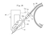
- the guidewire driver 70 has a guidewire insertion section 72 in which the end of a holder tube 81 that holds the guidewire 80 is held and into which the guidewire 80 is inserted, a guidewire driver 71 that moves the inserted guidewire 80, and a connecting section 73 that is connected to the insertion section 62a of the hub 62 of the puncture device 41.
- the guidewire driver 71 has two roller sections 71a that sandwich the guidewire 80, and can move the guidewire 80 in both longitudinal directions.
- the guidewire driving device 70 is connected to the hub 62 after the puncture device 41 has been punctured into the blood vessel by the puncture driving unit 21.
- the guidewire driving device 70 is connected to the hub 62 by the surgeon, but a connecting device may also be provided that moves the guidewire driving device 70 and connects it to the hub 62. This allows the guidewire driving device 70 to be automatically connected to the puncture device 41.
- the puncture drive unit 21 is not limited to the configuration of the puncture drive unit 21 of this embodiment as long as it can drive the puncture device 41 to perform puncture.
- the vascular puncture device 10 has a puncture drive unit 91 consisting of a robot arm that can move the puncture device 41 three-dimensionally, and a probe body 20.
- the puncture drive unit 91 can puncture the puncture device 41 from any position and at any angle by control based on a sensor (not shown).
- the puncture driving part 91 punctures the arm H with the puncture device 41 according to the determined puncture possibility, puncture position or direction, and puncture parameters, and the puncture is controlled by detecting backflow blood.
- the blood vessel puncture device 10 is a blood vessel puncture device 10 that punctures a living body using a puncture device 41, and includes a puncture drive unit 21 that punctures the living body with the puncture device 41, a backflow blood detection unit 35 that detects backflow blood flowing from the blood vessel into the puncture device 41, and a control unit 30 that drives the puncture drive unit 21 to control the position of the puncture device 41 based on information on the backflow blood detected by the backflow blood detection unit 35.
- the blood vessel puncture device 10 configured in this manner controls the position of the puncture device 41 based on information on the backflow blood that occurs when the puncture device 41 punctures the blood vessel, and therefore can perform puncture with high accuracy because the position can be controlled after accurately grasping the state of puncture of the blood vessel by the puncture device 41.
- the puncture device 41 is composed of an inner needle 60, and the control unit 30 may be configured to stop the insertion of the puncture device 41 when the backflow blood detection unit 35 detects backflow blood flowing from the blood vessel into the base end side of the inner needle 60 while the puncture drive unit 21 is inserting the puncture device 41.
- the blood vessel puncture device 10 can confirm that the puncture device 41 has entered the blood vessel by detecting backflow blood, and can therefore determine with high accuracy whether the blood vessel has been punctured.
- the vascular puncture device 10 of (1) above further includes a probe body 20 equipped with an imaging unit 22 that acquires cross-sectional images of the human body, and the puncture device 41 is composed of an inner needle 60.
- the control unit 30 calculates the estimated insertion depth of the puncture device 41 based on the cross-sectional image acquired by the imaging unit 22, and when the puncture drive unit 21 is inserting the puncture device 41 and the backflow detection unit 35 detects backflow blood flowing from the blood vessel to the base end side of the inner needle 60, the control unit 30 continues inserting the puncture device 41, and when the insertion depth of the puncture device 41 reaches the estimated calculated depth, the control unit 30 acquires a cross-sectional image with the imaging unit 22 and determines whether the positional relationship between the inner needle 60 and the blood vessel is normal based on the acquired cross-sectional image.
- the control unit 30 stops inserting the puncture device 41, and if the positional relationship between the inner needle 60 and the blood vessel is normal, a certain interruption process may be performed. This allows the blood vessel puncture device 10 to insert the puncture device 41 deeper into the blood vessel than immediately after the puncture device 41 penetrates the blood vessel wall, allowing for reliable puncture.
- the blood vessel puncture device 10 of (1) above may further include a probe body 20 equipped with an imaging unit 22 for acquiring cross-sectional images of the human body, the puncture device 41 being composed of an inner needle 60, and the control unit 30 may calculate the estimated insertion depth of the puncture device 41 based on the cross-sectional images acquired by the imaging unit 22, and while the puncture drive unit 21 is inserting the puncture device 41, the backflow detection unit 35 may detect backflow blood flowing from the blood vessel to the base end side of the inner needle 60, and when the insertion depth of the puncture device 41 reaches the estimated calculated depth, the insertion of the puncture device 41 may be stopped. This allows the blood vessel puncture device 10 to insert the puncture device 41 deeper into the blood vessel than in the state immediately after the puncture device 41 penetrates the blood vessel wall, thereby enabling reliable puncture.
- the blood vessel puncture device 10 of (1) above may further include a probe body 20 equipped with an imaging unit 22 for acquiring cross-sectional images of the human body, the puncture device 41 being composed of an inner needle 60, and the control unit 30 may calculate a correlation between the expected amount of backflow blood and the insertion depth of the puncture device 41 based on the cross-sectional images acquired by the imaging unit 22, and while the puncture drive unit 21 is inserting the puncture device 41, determine whether the state of backflow blood detected by the backflow blood detection unit 35 matches the correlation, and if the state of backflow blood matches the correlation, continue inserting the puncture device 41, and if the state of backflow blood does not match the correlation, perform a certain interruption process. This allows the blood vessel puncture device 10 to more accurately grasp the puncture position of the inner needle 60, improving the accuracy of puncture.
- the puncture device 41 has an inner needle 60 and an outer tube 61 that covers the inner needle 60, and the inner needle 60 has a tip that protrudes from the tip of the outer tube 61 and can be removed from the outer tube 61 by the puncture drive unit 21.
- the puncture drive unit 21 is inserting the puncture device 41 and the backflow detection unit 35 detects first backflow blood flowing from the blood vessel between the inner needle 60 and the outer tube 61
- the control unit 30 continues inserting the puncture device 41 and the puncture drive unit 21 detects the first backflow blood flowing from the blood vessel between the inner needle 60 and the outer tube 61.
- the backflow detection unit 35 detects the stop of the first backflow, the insertion of the puncture device 41 is stopped, the inner needle 60 is removed from the outer tube 61 when the insertion of the puncture device 41 is stopped, the outer tube 61 is moved to the base end side when the inner needle 60 is removed from the outer tube 61, and when the puncture drive unit 21 is moving the outer tube 61 to the base end side, if the backflow detection unit 35 detects the second backflow blood flowing from the blood vessel into the base end side of the outer tube 61 while the puncture drive unit 21 is moving the outer tube 61 to the base end side, the movement of the outer tube 61 may be stopped.
- the blood vessel puncture device 10 can perform puncture by penetrating the blood vessel once in the puncture device 41 having the outer tube 61 on the outside of the inner needle 60, removing the inner needle 60, and placing only the outer tube 61 in the blood vessel while detecting the backflow blood.
- the puncture device 41 has an inner needle 60 and an outer tube 61 that covers the inner needle 60, and the inner needle 60 has a tip that protrudes from the tip of the outer tube 61 and can be removed from the outer tube 61 by the puncture drive unit 21.
- the control unit 30 may be configured to stop the insertion of the puncture device 41 when the backflow detection unit 35 detects the first backflow blood flowing from the blood vessel between the inner needle 60 and the outer tube 61 while the puncture drive unit 21 is inserting the puncture device 41, and to stop the movement of the outer tube 61 when the backflow detection unit 35 detects the cessation of the first backflow blood after the backflow detection unit 35 detects the second backflow blood flowing from the blood vessel into the base end side of the outer tube 61 while the puncture drive unit 21 is moving the outer tube 61 toward the base end.
- the blood vessel puncture device 10 to use a puncture device 41 that has an outer tube 61 on the outside of an inner needle 60 to pierce a blood vessel, remove the inner needle 60, and then place only the outer tube 61 inside the blood vessel while detecting backflow of blood.
- the blood vessel puncture device 10 of any of (1) to (7) above may further include a notification unit 23 controlled by the control unit 30, and the control unit 30 may cause the notification unit 23 to notify when it determines that the tip of the puncture device 41 is located inside the blood vessel based on information about backflow from the backflow detection unit 35. This allows the surgeon to smoothly perform the procedure after puncture.
- the blood vessel puncture device 10 of any of (1) to (8) above may further include a guidewire driver 71 that inserts a guidewire 80 into the puncture device 41, and the control unit 30 may cause the guidewire driver 71 to insert the guidewire 80 into the blood vessel when it determines that the tip of the puncture device 41 is located inside the blood vessel from backflow blood information provided by the backflow blood detection unit 35. This allows the blood vessel puncture device 10 to automate the insertion of the guidewire 80 that is performed after puncture by the puncture device 41.
- the present invention is not limited to the above-described embodiment, and various modifications can be made by those skilled in the art within the technical concept of the present invention.
- a monitor for displaying the cross-sectional image acquired in this embodiment is not shown, the vascular puncture device 10 may be connected to a monitor so that the cross-sectional image can be viewed.
- the vascular puncture device 10 may be configured such that the puncture drive unit 21, the backflow detection unit 35, and the control unit 30 are each wirelessly connected to each other so that information can be sent and received.
Landscapes
- Health & Medical Sciences (AREA)
- Life Sciences & Earth Sciences (AREA)
- Surgery (AREA)
- Medical Informatics (AREA)
- Animal Behavior & Ethology (AREA)
- Engineering & Computer Science (AREA)
- Biomedical Technology (AREA)
- Heart & Thoracic Surgery (AREA)
- Pathology (AREA)
- Molecular Biology (AREA)
- Nuclear Medicine, Radiotherapy & Molecular Imaging (AREA)
- General Health & Medical Sciences (AREA)
- Public Health (AREA)
- Veterinary Medicine (AREA)
- Physics & Mathematics (AREA)
- Biophysics (AREA)
- Radiology & Medical Imaging (AREA)
- Ultra Sonic Daignosis Equipment (AREA)
- Infusion, Injection, And Reservoir Apparatuses (AREA)
Priority Applications (2)
| Application Number | Priority Date | Filing Date | Title |
|---|---|---|---|
| JP2024549335A JPWO2024070976A1 (https=) | 2022-09-26 | 2023-09-22 | |
| US19/090,233 US20250221736A1 (en) | 2022-09-26 | 2025-03-25 | Vascular puncture apparatus |
Applications Claiming Priority (2)
| Application Number | Priority Date | Filing Date | Title |
|---|---|---|---|
| JP2022152985 | 2022-09-26 | ||
| JP2022-152985 | 2022-09-26 |
Related Child Applications (1)
| Application Number | Title | Priority Date | Filing Date |
|---|---|---|---|
| US19/090,233 Continuation US20250221736A1 (en) | 2022-09-26 | 2025-03-25 | Vascular puncture apparatus |
Publications (1)
| Publication Number | Publication Date |
|---|---|
| WO2024070976A1 true WO2024070976A1 (ja) | 2024-04-04 |
Family
ID=90477762
Family Applications (1)
| Application Number | Title | Priority Date | Filing Date |
|---|---|---|---|
| PCT/JP2023/034583 Ceased WO2024070976A1 (ja) | 2022-09-26 | 2023-09-22 | 血管穿刺装置 |
Country Status (3)
| Country | Link |
|---|---|
| US (1) | US20250221736A1 (https=) |
| JP (1) | JPWO2024070976A1 (https=) |
| WO (1) | WO2024070976A1 (https=) |
Citations (4)
| Publication number | Priority date | Publication date | Assignee | Title |
|---|---|---|---|---|
| CN104188712A (zh) * | 2014-08-07 | 2014-12-10 | 王燕青 | 一种自动式动脉穿刺器及使用方法 |
| WO2019235518A1 (ja) * | 2018-06-06 | 2019-12-12 | テルモ株式会社 | 穿刺システム |
| WO2022153727A1 (ja) * | 2021-01-18 | 2022-07-21 | テルモ株式会社 | 超音波プローブ |
| WO2023002934A1 (ja) * | 2021-07-21 | 2023-01-26 | テルモ株式会社 | 血管穿刺装置および血管穿刺システム |
-
2023
- 2023-09-22 JP JP2024549335A patent/JPWO2024070976A1/ja active Pending
- 2023-09-22 WO PCT/JP2023/034583 patent/WO2024070976A1/ja not_active Ceased
-
2025
- 2025-03-25 US US19/090,233 patent/US20250221736A1/en active Pending
Patent Citations (4)
| Publication number | Priority date | Publication date | Assignee | Title |
|---|---|---|---|---|
| CN104188712A (zh) * | 2014-08-07 | 2014-12-10 | 王燕青 | 一种自动式动脉穿刺器及使用方法 |
| WO2019235518A1 (ja) * | 2018-06-06 | 2019-12-12 | テルモ株式会社 | 穿刺システム |
| WO2022153727A1 (ja) * | 2021-01-18 | 2022-07-21 | テルモ株式会社 | 超音波プローブ |
| WO2023002934A1 (ja) * | 2021-07-21 | 2023-01-26 | テルモ株式会社 | 血管穿刺装置および血管穿刺システム |
Non-Patent Citations (4)
| Title |
|---|
| "Practical guide for safe central venous catheterization and management 2017", JOURNAL OF ANESTHESIA, SPRINGER SINGAPORE, SINGAPORE, vol. 34, no. 2, 30 November 2019 (2019-11-30), Singapore, pages 167 - 186, XP037121151, ISSN: 0913-8668, DOI: 10.1007/s00540-019-02702-9 * |
| ASAI, YASUFUMI: "Arterial puncture and catheterization", SURGICAL THERAPY - GEKA CHIRYO, NAGAI SHOTEN CO. LTD., JP, vol. 74, no. 5, 1 May 1996 (1996-05-01), JP , pages 597 - 600, XP009554357, ISSN: 0433-2644 * |
| NAGAHAMA, SHOTARO: "Summary of important points for securing and placing blood vessels", JOURNAL OF VETERINARY ANESTHESIOLOGY, vol. 44, no. Suppl.2, 20 December 2013 (2013-12-20), pages 80, XP009554065, ISSN: 0916-5908 * |
| SHOTARO SUMITANI: "An Algorithm for Peripheral-Short Catheter Insertion in Vascular Access", JAPANESE JOURNAL OF NURSING ART AND SCIENCE, vol. 15, no. 1, 1 January 2016 (2016-01-01), pages 81 - 86, XP093156785, DOI: 10.18892/jsnas.15.1_81 * |
Also Published As
| Publication number | Publication date |
|---|---|
| US20250221736A1 (en) | 2025-07-10 |
| JPWO2024070976A1 (https=) | 2024-04-04 |
Similar Documents
| Publication | Publication Date | Title |
|---|---|---|
| US12165315B2 (en) | Ultrasound system with pressure and flow determination capability | |
| JP7182240B2 (ja) | 穿刺システム及び穿刺制御装置 | |
| CN108836440B (zh) | 一种穿刺辅助机器人的控制决策方法与系统 | |
| KR101948539B1 (ko) | 초음파 탐촉 기반의 주사기 정렬 유도장치 | |
| US20240139435A1 (en) | Vascular puncture assistance device | |
| EP1893093A1 (en) | System for guiding a probe over the surface of the skin of a patient or an animal | |
| JP2014150928A (ja) | 超音波診断装置 | |
| JP3180605B2 (ja) | 穿刺超音波プローブ | |
| US20230355349A1 (en) | Medical device | |
| WO2023002933A1 (ja) | 血管穿刺装置および血管穿刺システム | |
| CN104856725A (zh) | 血压测量装置 | |
| US12544035B2 (en) | Ultrasound probe | |
| WO2024070978A1 (ja) | 血管穿刺装置および血管判定装置 | |
| WO2024070976A1 (ja) | 血管穿刺装置 | |
| JP4365841B2 (ja) | 超音波診断装置 | |
| JP2005066310A (ja) | 静脈注射装置 | |
| KR101783207B1 (ko) | 흡입 시술 지원 시스템 및 방법 | |
| JP2016116747A (ja) | 血管穿刺用補助装置、及びこれを用いた血管穿刺装置 | |
| CN108992143A (zh) | 一种静脉穿刺装置及静脉穿刺控制方法 | |
| WO2024070977A1 (ja) | 逆血抑制装置 | |
| JP2004313271A (ja) | 超音波診断装置 | |
| WO2022153726A1 (ja) | 血管位置表示器 | |
| WO2024070931A1 (ja) | 血管穿刺装置および血管穿刺システムの制御方法 | |
| WO2023002934A1 (ja) | 血管穿刺装置および血管穿刺システム | |
| US6899678B2 (en) | Puncture difficulty evaluating device |
Legal Events
| Date | Code | Title | Description |
|---|---|---|---|
| 121 | Ep: the epo has been informed by wipo that ep was designated in this application |
Ref document number: 23872201 Country of ref document: EP Kind code of ref document: A1 |
|
| WWE | Wipo information: entry into national phase |
Ref document number: 2024549335 Country of ref document: JP |
|
| NENP | Non-entry into the national phase |
Ref country code: DE |
|
| 122 | Ep: pct application non-entry in european phase |
Ref document number: 23872201 Country of ref document: EP Kind code of ref document: A1 |