WO2024070952A1 - カバー及びこのカバーを用いた記録装置 - Google Patents
カバー及びこのカバーを用いた記録装置 Download PDFInfo
- Publication number
- WO2024070952A1 WO2024070952A1 PCT/JP2023/034526 JP2023034526W WO2024070952A1 WO 2024070952 A1 WO2024070952 A1 WO 2024070952A1 JP 2023034526 W JP2023034526 W JP 2023034526W WO 2024070952 A1 WO2024070952 A1 WO 2024070952A1
- Authority
- WO
- WIPO (PCT)
- Prior art keywords
- layer
- cover
- width
- narrow
- gasket
- Prior art date
- Legal status (The legal status is an assumption and is not a legal conclusion. Google has not performed a legal analysis and makes no representation as to the accuracy of the status listed.)
- Ceased
Links
Images



Classifications
-
- G—PHYSICS
- G11—INFORMATION STORAGE
- G11B—INFORMATION STORAGE BASED ON RELATIVE MOVEMENT BETWEEN RECORD CARRIER AND TRANSDUCER
- G11B33/00—Constructional parts, details or accessories not provided for in the other groups of this subclass
- G11B33/12—Disposition of constructional parts in the apparatus, e.g. of power supply, of modules
-
- G—PHYSICS
- G11—INFORMATION STORAGE
- G11B—INFORMATION STORAGE BASED ON RELATIVE MOVEMENT BETWEEN RECORD CARRIER AND TRANSDUCER
- G11B33/00—Constructional parts, details or accessories not provided for in the other groups of this subclass
- G11B33/14—Reducing influence of physical parameters, e.g. temperature change, moisture, dust
Definitions
- the present invention relates to a cover for a recording device such as a hard disk drive and a recording device using this cover.
- Hard disk drives which are used as recording devices, house the internal mechanisms, including the disk that serves as the recording medium, in a space that must be sealed to prevent dust, moisture, etc. from entering.
- a gasket is generally provided between the base and cover of the housing that defines the space (see, for example, Patent Document 1).
- the gasket is provided in a circumferential shape along the outer periphery of the cover that is received on the base, and is compressed between the cover and the base.
- this gasket may have a narrow portion where the width is narrowed partially on the inside and outside of the circumference.
- the narrow portion can be easily set by changing the discharge conditions, such as the amount of discharge.
- the height by which the narrow portion protrudes from the cover is determined to some extent by the width of the liquid gasket when it is dispensed, so the protruding height of the narrow portion is smaller than that of other parts of the gasket. As a result, there is a risk that the narrow portion may reduce the sealing performance of the gasket.
- the problem to be solved was that the protruding height of the narrow part of the gasket was small, which could reduce the sealing performance.
- the present invention provides a cover that is attached to an opening of a base of a housing that accommodates an internal mechanism within a space, closing the space.
- the cover has an outer periphery that is received on the base, and a gasket that extends circumferentially along the outer periphery, protrudes from the outer periphery, and is compressed by contact with the base.
- the gasket has a large portion that is relatively wide from the inside to the outside of the periphery, and a small portion that is relatively narrow. The small portion is raised in the compression direction of the gasket by a layer structure that has a raising layer.
- the present invention also provides a recording device using the above cover.
- This recording device includes a base that, together with the cover, forms a housing and houses an internal mechanism within a closed space.
- the base includes an opening to which the cover is attached, and a cover receiving portion that receives the outer periphery of the cover with the gasket interposed therebetween.
- the protruding height of the gasket in the compression direction at the narrow width portion can be increased by raising the height, thereby improving the sealing performance of the gasket.
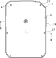
- FIG. 1 is a plan view of a recording apparatus according to a first embodiment of the present invention.
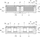
- 2A is a schematic cross-sectional view of the recording apparatus of FIG. 1 taken along line II-II
- FIG. 2B is a schematic cross-sectional view of a modified example.
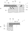
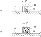
- 3A and 3B are schematic cross-sectional views showing an enlarged portion of FIG. 2A.
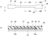
- FIG. 4 is a bottom view of the cover of the recording device of FIG. 5A is a bottom view of the cover of FIG. 4 showing the periphery of a narrow portion of a gasket provided on the cover
- FIG. 5B is a cross-sectional view taken along line VV of FIG. 5A.
- 6A is a cross-sectional view taken along line VIA-VIA in FIG.
- FIG. 5A and FIG. 6B is a cross-sectional view taken along line VIB-VIB in FIG. 5A.
- FIG. 7 is a graph showing an example of the correlation between gasket width and protrusion height in a single layer.
- FIG. 8A is a cross-sectional view showing the periphery of a narrow width portion of a gasket according to a second embodiment of the present invention
- FIG. 8B is a cross-sectional view taken along line VIII-VIII in FIG. 8A.
- FIG. 9 is a cross-sectional view showing the periphery of a narrow width portion of a gasket according to a third embodiment of the present invention.
- FIG. 10(A) is a bottom view of a cover showing the periphery of a narrow portion of a gasket according to a fourth embodiment of the present invention
- FIG. 10(B) is a cross-sectional view taken along line XX of FIG. 10(A).
- FIG. 11 is a cross-sectional view of a gasket according to a modified example of the fourth embodiment.
- the goal of improving the sealing performance of a gasket with a narrow section was achieved by raising the narrow section.
- the cover 19 is attached to the opening 17a of the base 17 of the housing 3, which houses the internal mechanism 5 in the space 3a, to close the space 3a.
- the cover 19 has an outer periphery 19a that is received on the base 17, and a gasket 29 that extends circumferentially along the outer periphery 19a, protruding from the outer periphery 19a and being compressed by contact with the base 17.
- the gasket 29 has a large width portion 31 that is relatively large from the inside to the outside of the circumferential shape, and a small width portion 33 that is relatively small in width.
- the small width portion 33 is raised in the compression direction of the gasket 29 by a layer structure having a raising layer 35 or 37.
- the narrow portion 33 may include a first layer 35 as a bulking layer and a second layer 37 laminated on the first layer 35, and the wide portion 31 may be formed integrally with the second layer 37 of the narrow portion 33.
- a transition portion 39 may be provided between the second layer 37 of the narrow portion 33 and the wide portion 31, the width of which and the height of the gasket 29 in the compression direction gradually decrease from the wide portion 31 to the narrow portion 33.
- the end 35a of the first layer 35 of the narrow portion 33 in the extension direction of the gasket 29 may be located within the transition portion 39, and may be configured so that the width and height in the compression direction gradually increase as it moves away from the wide portion 31 in the extension direction.
- the large width portion 31 can be a single layer or multiple layers. If it is multiple layers, it may have a first layer 41 and a second layer 43 that are integral with the first layer 35 and second layer 37, respectively, of the narrow width portion 33. In this case, the second layer 43 of the large width portion 31 may be configured to include the first layer 41 of the large width portion 31.
- the narrow portion 33 may have the second layer 37 as a bulking layer.
- the first layer 35 is formed integrally with the wide portion 31, and the second layer 37 is laminated on the first layer.
- a transition portion may be provided between the first layer 35 of the narrow portion 33 and the wide portion 31.
- the end 37a of the second layer 37 of the narrow portion 33 in the extension direction of the gasket 29 may be located on the transition portion 39, and the width and height in the compression direction may gradually increase as it moves away from the wide portion 31 in the extension direction.
- the narrow portion 33 and the wide portion 31 may be offset in the width direction. Also, the first layer 35 and the second layer 37 of the narrow portion 33 may be offset in the width direction.
- the recording device 1 using the cover 19 has a base 17 which, together with the cover 19, constitutes a housing 3 and houses an internal mechanism 5 within a closed space 3a.
- the base 17 has an opening 17a to which the cover 19 is attached, and a cover receiving portion 25 which receives the outer periphery 19a of the cover 19 with a gasket 29 interposed therebetween.
- FIG. 1 is a plan view of a recording apparatus according to a first embodiment of the present invention.
- Fig. 2(A) is a schematic cross-sectional view taken along line II-II of the recording apparatus in Fig. 1
- Fig. 2(B) is a schematic cross-sectional view of a modified example.
- Fig. 3(A) and Fig. 3(B) are schematic cross-sectional views each showing an enlarged view of a portion around the gaskets on both sides of Fig. 2(A).
- the recording device 1 in this embodiment is a hard disk drive serving as a magnetic disk device, and contains an internal mechanism 5 in a space 3a within a housing 3.
- the internal mechanism 5 includes disks 7 as recording media, as well as a spindle motor 9.
- a plurality of disks 7 are stacked in the thickness direction of the recording device 1 (hereinafter simply referred to as the "thickness direction") and are rotatably supported by the spindle motor 9. Information is written to and read from these disks 7 via a head (not shown).
- the recording device 1 is not limited to a magnetic disk device, but may be other disk devices such as optical disk devices, or other recording devices other than disk devices.
- the recording device 1 may be a tape-embedded drive, as shown in FIG. 2(B).
- a tape film 13 as a recording medium wound between two tape reels 11 and a head assembly 15 for reading and writing information are housed in the space 3a of the housing 3 as the internal mechanism 5.
- the housing 3 is composed of a base 17 and a cover 19, and seals or closes the interior.
- the base 17 is made of a metal such as aluminum, and is configured in a box shape with an opening 17a on one side in the thickness direction.
- the base 17 may have any suitable shape as long as it is box-shaped and capable of housing the internal mechanism 5 including the disk 7.
- the base 17 has, for example, a substantially rectangular shape in a plan view. Note that a plan view refers to the state when viewed from the thickness direction, and does not distinguish between the top surface and the bottom surface.
- This base 17 has a cover 19 attached to one opening 17a in the thickness direction to close it. This seals the space 3a inside the housing 3 that houses the internal mechanism 5.
- This sealed space 3a may be filled with a gas that has less resistance than air, such as helium.
- the outer periphery of the base 17 is provided with a side wall portion 21a in a circumferential manner, and the opening 17a of the base 17 is defined by the side wall portion 21a.
- the outer periphery of the base 17 is the outer periphery region that surrounds the internal mechanism 5, and in this embodiment, refers to the portion where the side wall portion 21a is provided.
- the side wall portion 21a is integrally erected from the plate-shaped bottom wall portion 21b of the base 17.
- the side wall portion 21a can also be formed as a separate piece from the bottom wall portion 21b of the base 17 and then joined to form an integral piece.
- This side wall portion 21a is provided with a fastening portion 23 and a cover receiving portion 25.
- the fastening portion 23 of the base 17 is a portion that fastens the cover 19 to the base 17.
- the fastening portion 23 is provided at multiple locations, for example, six locations, spaced apart in the circumferential direction of the base 17.
- the fastening portion 23 may be formed in a circular shape along the outer periphery of the base 17.
- the circumferential direction of the base 17 means the circumferential direction along the side wall portion 21a of the base 17.
- the fastening portion 23 receives the cover 19 by joining it in the thickness direction.
- the cover 19 is fastened to the fastening portion 23 by a fastener, for example, a bolt 27.
- the cover 19 is also fastened to the spindle motor 9 by a bolt 27.
- a fastener a rivet or the like may be used in addition to the bolt 27.
- the cover receiving portion 25 receives the outer periphery 19a of the cover 19 with the gasket 29 attached to the cover 19 interposed therebetween. This causes the gasket 29 to be compressed in the thickness direction between the cover receiving portion 25 and the cover 19.
- the cover receiving portion 25 is provided in a circular shape in a plan view along the side wall portion 21a of the base 17.
- the cover receiving portion 25 may also be provided partially on the outer periphery of the base 17.
- This cover receiving portion 25 has a receiving surface 25a that is configured flat along the width direction.
- the gasket 29 is abutted against this receiving surface 25a to receive the outer periphery 19a of the cover 19.
- the receiving surface 25a does not have to be flat, and may have irregularities, etc., as long as the gasket 29 can be abutted against it.
- Figure 4 is a bottom view of the cover of the recording device in Figure 1.
- the cover 19 is made of a metal plate such as aluminum.
- the cover 19 is formed in a flat plate shape that covers the opening 17a of the base 17 as a whole.
- the cover 19 in this embodiment has a substantially rectangular shape in a plan view to correspond to the base 17.
- the shape and other configuration of the cover 19 is not particularly limited as long as it covers the opening 17a of the base 17.
- the material of the cover 19 is also arbitrary.
- the cover 19 has its outer periphery 19a received by the base 17 while covering the opening 17a of the base 17. Specifically, the outer periphery 19a of the cover 19 is received in the thickness direction by the cover receiving portion 25 of the base 17. The outer periphery 19a is a circular portion that is received by the base 17. A sealing gasket 29 is attached to the outer periphery 19a of the cover 19.
- the gasket 29 extends circumferentially along the outer periphery 19a of the cover 19.
- the gasket 29 protrudes in the thickness direction from the outer periphery 19a and is compressed by contact with the base 17.
- the gasket 29 protruding from the outer periphery 19a of the cover 19 abuts against the cover receiving portion 25 of the base 17, and is compressed and interposed between the base 17 and the cover 19 in response to the fixation of the cover 19 to the base 17.
- the protruding direction and compression direction of the gasket 29 coincide with the thickness direction, but they can be different. Also, while it is preferable that the protruding direction and compression direction of the gasket 29 coincide, they can be different as long as the gasket 29 is convex in the compression direction relative to the cover 19 and can ensure airtightness through compression. In the following, in this embodiment, the protruding direction and compression direction will be described as the thickness direction.
- the compressed gasket 29 creates a seal between the cover 19 and the base 17.
- the gasket 29 is compressed between the cover 19 and the cover receiving portion 25 of the base 17, creating a seal between the cover 19 and the cover receiving portion 25.
- the gasket 29 in this embodiment is a liquid gasket such as a Foamed In Place Gasket (FIPG).
- FIPG Foamed In Place Gasket
- the gasket 29 is applied in advance to the outer periphery 19a of the cover 19 by dispensing it from an applicator such as a needle, and is fixed by hardening.
- Fig. 5(A) is a bottom view of cover 19 in Fig. 4 showing the periphery of the narrow portion of the gasket provided on cover 19, and Fig. 5(B) is a cross-sectional view taken along line V-V in Fig. 5(A).
- Fig. 6(A) is a cross-sectional view taken along line VIA-VIA in Fig. 5(A), and Fig. 6(B) is a cross-sectional view taken along line VIB-VIB in Fig. 5(A).
- Fig. 5(B) shows a cross section along the extension direction and thickness direction of the gasket 19
- Figs. 6(A) and (B) show cross sections perpendicular to the extension direction of the gasket 19.
- Figs. 6(A) and (B) also show the relationship between the first layer 35, second layer 37, and transition portion 39 of the narrow width portion 33, and show a conceptual angular cross section of the narrow width portion 33.
- the gasket 29 in this embodiment has a large width portion 31 and a small width portion 33.
- the large width portion 31 is a portion of the gasket 29 that is relatively wide from inside to outside
- the narrow width portion 33 is a portion of the gasket 29 that is relatively narrow from inside to outside.
- the adjacent large width portion 31 and narrow width portion 33 are arranged concentrically in the width direction. "Concentrically” means that the centers of the large width portion 31 and narrow width portion 33 coincide in the width direction.
- the widths of the narrow portion 33 and the wide portion 31 refer to the largest widths (maximum widths) in the narrow portion 33 and the wide portion 31, respectively, but may also refer to the smallest widths (minimum widths) or average widths. Within the wide portion 31 and the narrow portion 33, the widths are constant in the extension direction, but may vary in the extension direction.
- the narrow width portion 33 is a portion of the gasket 29 that is narrowed in the extension direction due to space constraints such as to avoid interference with the internal mechanism 5. Note that one or more narrow width portions 33 are provided in the extension direction.
- the narrow portion 33 is raised in the thickness direction, which is the compression direction of the gasket 29, by a layer structure having a raised layer. Raising refers to making the narrow portion 33 taller in the thickness direction than if it had the same number of layers as the large portion 31.
- the number of layers here refers to the number of layers stacked on top of one layer, and does not include the number of layers that are included.
- An included layer is a multi-layer structure in which another layer is embedded within a layer, and in terms of the number of layers, it becomes a single layer of one layer. Therefore, the narrow portion 33 has a greater number of layers than the large portion 31, including the raised layer.
- the protruding height refers to the height in the thickness direction, which is the direction in which the gasket 29 protrudes from the cover 19.
- the protruding height of the gasket 29 in this embodiment is the same between the narrow portion 33 and the wide portion 31 in the free state. However, it is also possible to make the protruding height of the gasket 29 greater or smaller in the narrow portion 33 than in the wide portion 31.
- the free state refers to an unloaded state in which no compressive load is acting on the gasket 29, and in this embodiment, refers to the pre-closing state before the opening 17a of the base 17 is closed by the cover 19.
- the large width portion 31 is a single layer
- the narrow width portion 33 is multiple layers, in particular two layers.
- the number of layers of the large width portion 31 and the narrow width portion 33 can be set arbitrarily as long as the narrow width portion 33 can be raised.
- the single layer of the large width portion 31 here means a single layer in terms of the layer structure and number of layers, unlike inclusion.
- hereinafter, when simply referring to a single layer it means a single layer in terms of the layer structure and number of layers.
- the width and height in the thickness direction of the large portion 31 of the single layer are set when the liquid gasket is discharged from the needle. Note that when simply referring to height, it refers to the dimension in the thickness direction, which is the compression direction, as opposed to the protruding height from the cover 19 (the same applies below).
- the width and height when the liquid gasket is discharged from the needle and hardened have a correlation such that one cannot be made larger or smaller than the other within the single layer.
- the width and height of the large portion 31 are set according to this correlation.
- Figure 7 shows an example of the correlation between width and height of a single layer gasket.
- different correlations C1 and C2 between width and height can be obtained by changing the discharge conditions, such as the amount of liquid gasket dispensed, the needle movement speed, and the distance between the application surface of the cover 19 and the applicator.
- the width (and height) of the wide portion 31 is adjusted within the range between these correlations C1 and C2.
- the needle movement speed refers to the movement speed in the extension direction.
- the two-layer narrow section 33 includes a first layer 35 and a second layer 37.
- the first layer 35 is a layer that contacts the cover 19 at the narrow width portion 33, and functions as a bulking layer.
- the second layer 37 is a layer that is laminated on the first layer 35 in the thickness direction. The second layer 37 is arranged concentrically with the first layer 35 in the width direction.
- the first layer 35 and the second layer 37 are made of liquid gasket of the same material.
- the first layer 35 and the second layer 37 may be liquid gaskets of different materials.
- the width and height of the first layer 35 and the second layer 37 are set in the same way as the large width portion 31 when the liquid gasket is discharged from the needle and applied to the cover 19.
- the first layer 35 and the second layer 37 When applying the first layer 35 and the second layer 37, the first layer 35 is applied, and then the second layer 37 is applied together with the large width portion 31.
- the first layer 35 When multiple small width portions 33 are present, the first layer 35 is applied at the positions corresponding to the small width portions 33.
- the second layer 37 is applied by changing the protrusion conditions at the positions corresponding to the small width portions 33 together with the application of the large width portions 31.
- the entire gasket 29 is then hardened. Note that the first layer 35 may be applied and then hardened, and the large width portions 31 and the second layer 37 may be applied and then hardened separately.
- the second layer 37 is formed integrally with the large portion 31 and has a constant width and height. Because the second layer 37 is formed integrally with the large portion 31, fluctuations in the protruding height of the gasket 29 can be suppressed and airtightness can be improved.
- a transition portion 39 is provided between the large portion 31 and the second layer 37 of the narrow portion 33, and the transition portion 39 allows a smooth transition between the large portion 31 and the second layer 37 of the narrow portion 33, suppressing fluctuations in the protruding height of the gasket 29 and improving airtightness.
- the transition portion 39 may be omitted.
- the transition section 39 gradually decreases in width and height from the large width section 31 to the small width section 33.
- "Gradually decreasing width and height” means that the width and height decrease continuously or in stages.
- the transition section 39 has a width that decreases continuously in a linear manner with inclination on both sides in the width direction, and a height that decreases continuously in a parabolic manner, but the shape can be set arbitrarily.
- both the width and height of the transition section 39 may decrease in a parabolic or linear manner.
- the gradual decrease in width and height may be a shape in which multiple sections with continuously decreasing width and height are connected by a section with constant width and height, or a shape in which multiple sections with different widths and heights are constant are connected.
- the end 35a in the extension direction of the first layer 35 is located within the transition section 39. Contrary to the transition section 39, this end 35a gradually increases in width and height as it moves away from the large width section 31 in the extension direction. This makes it possible to suppress fluctuations in the protruding height of the gasket 29 together with the transition section 39.
- Gradually increasing width and height means that the width and height increase continuously or in stages.
- the width and height increase continuously in a parabolic shape, but the width and height may also increase continuously in a linear shape.
- gradual increasing width and height may be a shape in which multiple parts with continuously increasing width and height are connected by a part with constant width and height, or a shape in which multiple parts with different constant widths and heights are connected.
- the width and height of the first layer 35 excluding the end 35a are constant and the same as those of the second layer 37. Therefore, in the width direction, the edge of the first layer 35 and the edge of the second layer 37 are aligned. Note that the width and height of the first layer 35 excluding the end 35a do not need to be the same as those of the second layer 37, and may be larger or smaller than those of the second layer 37.
- the difference in protruding height between the narrow portion 33 and the wide portion 31 is made smaller than when there is no raising by the first layer 35. This is because in order to ensure the airtightness of the gasket 29, it is preferable to suppress the variation in height between the narrow portion 33 and the wide portion 31.
- the cover 19 is attached to the base 17 of the housing 3 that accommodates the disk 7, and the space 3a of the housing 3 that accommodates the disk 7 is closed.
- the cover 19 to which the gasket 29 is attached is placed opposite the opening 17a of the base 17 in the thickness direction. In this state, the cover 19 and the base 17 are brought close to each other, and the tip of the gasket 29 is brought into contact with the cover receiving portion 25 of the base 17.
- the gasket 29 is compressed between the cover 19 and base 17.
- the gasket 29 of this embodiment is sufficiently compressed not only in the large portion 31 but also in the small width portion 33, because the protruding height of the small width portion 33 is increased by raising the height. Therefore, the gasket 29 can improve the overall airtightness.
- the second layer 37 which is the surface layer of the narrow portion 33, and the wide portion 31 are integrated, so the tip of the gasket 29 is smooth between the narrow portion 33 and the wide portion 31. Therefore, the gasket 29 can improve its sealing performance.
- the transition portion 39 between the second layer 37 of the narrow portion 33 and the wide portion 31 gradually becomes smaller in width and height toward the narrow portion 33.
- the end portion 35a of the first layer 35 of the narrow portion 33 is located within the transition portion 39, and the width and height gradually increase as it moves away from the wide portion 31 in the extension direction. This more reliably suppresses fluctuations in the protruding height of the gasket 29, improving airtightness.
- the cover 19 is fastened to the base 17 with the bolts 27 to close the space 3a of the housing 3 that contains the disk 7.
- FIG. 8(A) is a cross-sectional view showing the periphery of the narrow portion of the gasket according to the second embodiment of the present invention
- FIG. 8(B) is a cross-sectional view taken along line VIII-VIII in FIG. 8(A). Note that since the second embodiment has a common basic configuration to the first embodiment, the same reference numerals are used for corresponding components and redundant explanations will be omitted.
- FIG. 8(A) is a cross-section along the extension direction of the gasket. Also, FIG. 8(B) shows a conceptual cross-section of the wide portion 31 with an angular shape.
- the large width portion 31 of the gasket 29 is made of multiple layers. That is, the large width portion 31 has a first layer 41 and a second layer 43.
- the first layer 41 of the large width portion 31 is integrally and continuously formed with the first layer 35 of the narrow width portion 33, and has the same width and height as the first layer 35 of the narrow width portion 33. Note that the width and height of the first layer 41 of the large width portion 31 do not need to be the same as those of the narrow width portion 33.
- the second layer 43 of the large portion 31 has the same width and height as the large portion 31 of Example 1, and contains the first layer 41. Therefore, the second layer 43 of the large portion 31 is in a state in which the first layer 41 is embedded, and is a single layer in terms of the number of layers.
- the second layer 43 of the large width portion 31 is integral with the second layer 37 of the small width portion 33 and is continuous with the second layer 37 of the small width portion 33 via a transition portion 39.
- the transition portion 39 is gradually reduced in width and height toward the small width portion 33, as in Example 1.
- the other configurations are the same as in Example 1.
- the same effects as those of the first embodiment can be achieved, and in addition, the first layers 41 and 35 of the large width portion 31 and the small width portion 33 can be formed continuously and circumferentially together, making it easier to form the gasket 29.
- Figure 9 is a cross-sectional view showing the vicinity of the narrow portion of the gasket according to the third embodiment of the present invention. Note that since the third embodiment has a basic configuration in common with the first embodiment, the same reference numerals are used for corresponding configurations and duplicated explanations are omitted. Figure 9 is a cross-section along the extension direction of the gasket.
- the second layer 37 of the narrow width portion 33 is used as a raised layer.
- the first layer 35 of the narrow portion 33 is integral with the single-layer wide portion 31.
- the first layer 35 is continuous with the wide portion 31 via the transition portion 39.
- the wide portion 31 has the same width and height as in Example 1.
- the transition portion 39 gradually decreases in width and height toward the narrow portion 33, and the first layer 35 of the narrow portion 33 has the same constant width and height as the first layer 35 of Example 1. This forms a recess 45 from the transition portion 39 over the first layer 35 of the narrow portion 33.
- the second layer 37 of the narrow portion 33 is located within this recess 45.
- the recess 45 and the second layer 37 have the same cross-sectional shape.
- the second layer 37 has the same width and height on the first layer 35 as the second layer 37 of embodiment 1, and the end 37a, which gradually increases in width and height, is located on the transition portion 39.
- the cross-sectional shape of the second layer 37 may be larger or smaller than the recess 45. If the cross-sectional shape of the second layer 37 is larger than the recess 45, the second layer 37 will protrude in the thickness direction more than the large portion 31, and if the cross-sectional shape of the second layer 37 is smaller than the recess 45, the second layer 37 will be recessed in the thickness direction more than the large portion 31.
- Example 3 can achieve the same effects as Example 1.
- Fig. 10(A) is a bottom view of a cover showing the periphery of the narrow portion of a gasket according to Example 4 of the present invention
- Fig. 10(B) is a cross-sectional view along line X-X in Fig. 10(A).
- Example 4 has a common basic configuration to Example 1, so the same reference numerals are used for corresponding components and duplicated explanations will be omitted.
- Fig. 10(B) shows a conceptual angular cross section of the narrow portion 33.
- the narrow portion 33 is offset in the width direction relative to the wide portion 31. Accordingly, the shape of the transition portion 39 is changed from that of the first embodiment.
- the offset here refers to the deviation in the width direction between the center of the narrow portion 33 in the width direction and the center of the wide portion 31 in the width direction in a cross section perpendicular to the extension direction of the gasket 29.
- the narrow width portion 33 is eccentric so that its outer edge coincides with the outer edge of the wide width portion 31 in the width direction.
- the amount of eccentricity can be set appropriately, and the outer edge of the narrow width portion 33 does not have to coincide with the outer edge of the wide width portion 31.
- the transition portion 39 is designed so that the width gradually decreases only at the inner edge in the width direction. The rest is the same as in Example 1.
- Example 4 can achieve the same effect as Example 1.
- the eccentricity of the narrow portion 33 and the wide portion 31 can prevent the gasket 29 from protruding or bulging inward in the width direction when compressed.
- FIG. 11 is a cross-sectional view showing the narrow portion 33 of the gasket 29 according to a modified example of the fourth embodiment, in which the cross section of the narrow portion 33 is conceptually angular.
- the first layer 35 and the second layer 37 of the narrow width portion 33 are offset in the width direction. That is, the second layer 37 is set to be smaller in width and height than the first layer 35, and is offset outward in the width direction relative to the first layer 35. Due to this offset, the outer edge of the first layer 35 and the outer edge of the second layer 37 coincide in the width direction.
- eccentricity refers to the deviation in the width direction between the center of the width direction of the first layer 35 of the narrow width portion 33 and the center of the width direction of the second layer 37 of the narrow width portion 33 in a cross section perpendicular to the extension direction of the gasket 29.
- the amount of eccentricity can be set appropriately, and the outer edge of the first layer 35 and the outer edge of the second layer 37 do not need to coincide.
- the modified example in Figure 11 can be applied to the narrow width portion 33 of any of Examples 1 to 4.
- the eccentricity of the first layer 35 and the second layer 37 can prevent the gasket 29 from protruding or bulging inward in the width direction when compressed.
Landscapes
- Gasket Seals (AREA)
Abstract
Description
図1は、本発明の実施例1に係る記録装置の平面図である。図2(A)は、図1の記録装置のII-II線に係る概略断面図、図2(B)は、変形例に係る概略断面図である。図3は、図3(A)及び図3(B)は、図2(A)の両側のガスケット周辺の一部を拡大して示す概略断面図である。
本実施例の記録装置1の製造は、ディスク7を収容するハウジング3のベース17にカバー19を取り付けて、ディスク7を収容するハウジング3の空間部3aを閉止する。
3 ハウジング
3a 空間部
5 内部機構
17 ベース
17a 開口部
19 カバー
19a 外周部
25 カバー受け部
29 ガスケット
31 大幅部
33 小幅部
35 第一層(小幅部)
35a 端部
37 第二層(小幅部)
37a 端部
39 遷移部
41 第一層(大幅部)
43 第二層(大幅部)
Claims (10)
- 空間部に内部機構を収容するハウジングのベースの開口部に取り付けられて前記空間部を閉止するカバーであって、
前記ベースに受けられる外周部と、
該外周部に沿って周回状に延設され、前記外周部から突出して前記ベースへの当接により圧縮されるガスケットとを備え、
前記ガスケットは、前記周回状の内外にわたる幅が相対的に大きい大幅部及び該幅が相対的に小さい小幅部を備え、
前記小幅部は、嵩上げ層を有する層構造によって前記ガスケットの圧縮方向に嵩上げされた、
カバー。 - 請求項1のカバーであって、
前記小幅部は、前記嵩上げ層としての第一層と、該第一層上に積層された第二層とを備え、
前記大幅部は、前記小幅部の前記第二層と一体に形成され、
前記小幅部の前記第二層と前記大幅部との間は、前記大幅部から前記小幅部へ向けて漸次幅及び前記圧縮方向での高さが小さくなる遷移部を備えた、
カバー。 - 請求項2のカバーであって、
前記ガスケットの延設方向における前記小幅部の前記第一層の端部は、前記遷移部内に位置し、前記延設方向で前記大幅部から離れるにつれて幅及び前記圧縮方向での高さが漸次大きくなる、
カバー。 - 請求項2のカバーであって、
前記大幅部は、前記小幅部の前記第一層及び前記第二層とそれぞれ一体の第一層及び第二層を備え、
前記大幅部の前記第二層は、前記大幅部の前記第一層を内包する、
カバー。 - 請求項1~3の何れか一項のカバーであって、
前記大幅部は、単層である、
カバー。 - 請求項1のカバーであって、
前記小幅部は、第一層と、該第一層上に積層された前記嵩上げ層としての第二層とを備え、
前記大幅部は、前記小幅部の前記第一層と一体に形成され、
前記小幅部の前記第一層と前記大幅部との間は、前記大幅部から前記小幅部へ向けて幅及び前記圧縮方向での高さが漸次小さくなる遷移部を備えた、
カバー。 - 請求項6のカバーであって、
前記ガスケットの延設方向における前記小幅部の前記第二層の端部は、前記遷移部上に位置し、前記延設方向で前記大幅部から離れるにつれて漸次幅及び前記圧縮方向での高さが漸次大きくなる、
カバー。 - 請求項1~4、6、及び7のカバーであって、
前記小幅部及び前記大幅部は、幅方向において偏心している、
カバー。 - 請求項2~4、6、及び7のカバーであって、
前記小幅部の前記第一層及び前記第二層は、幅方向において偏心している、
カバー。 - 請求項1のカバーを用いた記録装置であって、
前記カバーと共にハウジングを構成し閉止された空間部内に内部機構を収容するベースを備え、
前記ベースは、前記カバーが取り付けられる開口部と、前記カバーの前記外周部を前記ガスケットを介在させつつ受けるカバー受け部とを備えた、
記録装置。
Priority Applications (1)
| Application Number | Priority Date | Filing Date | Title |
|---|---|---|---|
| JP2024549318A JP7851407B2 (ja) | 2022-09-30 | 2023-09-22 | カバー及びこのカバーを用いた記録装置 |
Applications Claiming Priority (2)
| Application Number | Priority Date | Filing Date | Title |
|---|---|---|---|
| JP2022158917 | 2022-09-30 | ||
| JP2022-158917 | 2022-09-30 |
Publications (1)
| Publication Number | Publication Date |
|---|---|
| WO2024070952A1 true WO2024070952A1 (ja) | 2024-04-04 |
Family
ID=90477708
Family Applications (1)
| Application Number | Title | Priority Date | Filing Date |
|---|---|---|---|
| PCT/JP2023/034526 Ceased WO2024070952A1 (ja) | 2022-09-30 | 2023-09-22 | カバー及びこのカバーを用いた記録装置 |
Country Status (2)
| Country | Link |
|---|---|
| JP (1) | JP7851407B2 (ja) |
| WO (1) | WO2024070952A1 (ja) |
Citations (4)
| Publication number | Priority date | Publication date | Assignee | Title |
|---|---|---|---|---|
| JP2006073067A (ja) * | 2004-08-31 | 2006-03-16 | Toshiba Corp | ディスク装置 |
| WO2008114484A1 (ja) * | 2007-03-16 | 2008-09-25 | Nhk Spring Co., Ltd. | カバーシール構造 |
| WO2011024812A1 (ja) * | 2009-08-26 | 2011-03-03 | Nok株式会社 | 金属ガスケット及び金属ガスケット用金型の製造方法 |
| JP6840728B2 (ja) * | 2016-03-23 | 2021-03-10 | 日本発條株式会社 | カバーアセンブリ、ハードディスク装置及びその製造方法 |
Family Cites Families (2)
| Publication number | Priority date | Publication date | Assignee | Title |
|---|---|---|---|---|
| JP4636229B2 (ja) | 2003-04-07 | 2011-02-23 | Nok株式会社 | ガスケットの製造方法 |
| US11017820B1 (en) | 2020-02-21 | 2021-05-25 | Seagate Technology Llc | Electromagnetic shielding for electronic devices |
-
2023
- 2023-09-22 JP JP2024549318A patent/JP7851407B2/ja active Active
- 2023-09-22 WO PCT/JP2023/034526 patent/WO2024070952A1/ja not_active Ceased
Patent Citations (4)
| Publication number | Priority date | Publication date | Assignee | Title |
|---|---|---|---|---|
| JP2006073067A (ja) * | 2004-08-31 | 2006-03-16 | Toshiba Corp | ディスク装置 |
| WO2008114484A1 (ja) * | 2007-03-16 | 2008-09-25 | Nhk Spring Co., Ltd. | カバーシール構造 |
| WO2011024812A1 (ja) * | 2009-08-26 | 2011-03-03 | Nok株式会社 | 金属ガスケット及び金属ガスケット用金型の製造方法 |
| JP6840728B2 (ja) * | 2016-03-23 | 2021-03-10 | 日本発條株式会社 | カバーアセンブリ、ハードディスク装置及びその製造方法 |
Also Published As
| Publication number | Publication date |
|---|---|
| JP7851407B2 (ja) | 2026-04-24 |
| JPWO2024070952A1 (ja) | 2024-04-04 |
Similar Documents
| Publication | Publication Date | Title |
|---|---|---|
| US7570455B2 (en) | Data storage device and magnetic disk drive in hermetically sealed condition | |
| US6631049B2 (en) | Sealed structure for an electronic device | |
| CN110931056B (zh) | 盘装置 | |
| US9190116B2 (en) | Hard disc drive cover seal | |
| US6876513B2 (en) | Rotary disk type storage device | |
| US20240431058A1 (en) | Recording device, manufacturing method therefor, and housing | |
| WO2006087948A1 (ja) | ガスケットによる密封構造 | |
| WO2024070952A1 (ja) | カバー及びこのカバーを用いた記録装置 | |
| JP7353577B2 (ja) | カバー及び記録装置 | |
| CN116913332A (zh) | 枢轴组件轴承装置和盘驱动装置 | |
| JP2003151228A (ja) | ディスク・ドライブ装置、モータ・デバイスおよびダンパ | |
| US6560063B1 (en) | Top cover for disk drive having stiffening features and gasket clearance enhancements | |
| US20190206448A1 (en) | Disk apparatus | |
| JPH1055662A (ja) | 磁気ディスク装置 | |
| JP7382542B1 (ja) | カバー、記録装置、及びカバーの製造方法 | |
| JP7847659B2 (ja) | 記録装置及びカバー | |
| JP4741294B2 (ja) | ハードディスクドライブのハウジング,ハードディスクドライブ | |
| US7319571B2 (en) | Overmold material and metal base interface design for leakage reduction in a disc drive | |
| JPH03260980A (ja) | 磁気ディスク装置 | |
| JP4762893B2 (ja) | シリンダヘッドガスケット | |
| US20060291095A1 (en) | Magnetic disk apparatus | |
| JP2007506889A6 (ja) | シリンダヘッドガスケット | |
| KR100425346B1 (ko) | 진동 저감 구조가 채용된 하드 디스크 드라이브 | |
| JP2023032866A (ja) | ディスク装置及びそのカバー | |
| JP2006234077A (ja) | ガスケットによる密封構造 |
Legal Events
| Date | Code | Title | Description |
|---|---|---|---|
| 121 | Ep: the epo has been informed by wipo that ep was designated in this application |
Ref document number: 23872178 Country of ref document: EP Kind code of ref document: A1 |
|
| WWE | Wipo information: entry into national phase |
Ref document number: 2024549318 Country of ref document: JP |
|
| WWE | Wipo information: entry into national phase |
Ref document number: 2501001935 Country of ref document: TH |
|
| NENP | Non-entry into the national phase |
Ref country code: DE |
|
| 122 | Ep: pct application non-entry in european phase |
Ref document number: 23872178 Country of ref document: EP Kind code of ref document: A1 |