WO2024070901A1 - 内燃機関の吸気構造 - Google Patents
内燃機関の吸気構造 Download PDFInfo
- Publication number
- WO2024070901A1 WO2024070901A1 PCT/JP2023/034358 JP2023034358W WO2024070901A1 WO 2024070901 A1 WO2024070901 A1 WO 2024070901A1 JP 2023034358 W JP2023034358 W JP 2023034358W WO 2024070901 A1 WO2024070901 A1 WO 2024070901A1
- Authority
- WO
- WIPO (PCT)
- Prior art keywords
- intake
- intake passage
- passage
- internal combustion
- combustion engine
- Prior art date
Links
- 238000002485 combustion reaction Methods 0.000 title claims abstract description 131
- 238000005192 partition Methods 0.000 claims abstract description 103
- 238000011144 upstream manufacturing Methods 0.000 claims abstract description 61
- 238000004891 communication Methods 0.000 claims abstract description 53
- 239000000446 fuel Substances 0.000 description 65
- 238000002347 injection Methods 0.000 description 26
- 239000007924 injection Substances 0.000 description 26
- 238000010586 diagram Methods 0.000 description 9
- 239000012212 insulator Substances 0.000 description 4
- 230000000694 effects Effects 0.000 description 3
- 238000005516 engineering process Methods 0.000 description 3
- 238000005094 computer simulation Methods 0.000 description 2
- 239000000203 mixture Substances 0.000 description 2
- 239000007787 solid Substances 0.000 description 2
- 230000002349 favourable effect Effects 0.000 description 1
- 230000006870 function Effects 0.000 description 1
- -1 i.e. Substances 0.000 description 1
- 238000009434 installation Methods 0.000 description 1
- 238000000034 method Methods 0.000 description 1
- 238000012986 modification Methods 0.000 description 1
- 230000004048 modification Effects 0.000 description 1
- 238000000746 purification Methods 0.000 description 1
- 238000012827 research and development Methods 0.000 description 1
- 238000000926 separation method Methods 0.000 description 1
- 230000003584 silencer Effects 0.000 description 1
- 238000005728 strengthening Methods 0.000 description 1
- 238000006467 substitution reaction Methods 0.000 description 1
- 230000007704 transition Effects 0.000 description 1
Images


Classifications
-
- F—MECHANICAL ENGINEERING; LIGHTING; HEATING; WEAPONS; BLASTING
- F02—COMBUSTION ENGINES; HOT-GAS OR COMBUSTION-PRODUCT ENGINE PLANTS
- F02B—INTERNAL-COMBUSTION PISTON ENGINES; COMBUSTION ENGINES IN GENERAL
- F02B31/00—Modifying induction systems for imparting a rotation to the charge in the cylinder
- F02B31/04—Modifying induction systems for imparting a rotation to the charge in the cylinder by means within the induction channel, e.g. deflectors
-
- F—MECHANICAL ENGINEERING; LIGHTING; HEATING; WEAPONS; BLASTING
- F02—COMBUSTION ENGINES; HOT-GAS OR COMBUSTION-PRODUCT ENGINE PLANTS
- F02M—SUPPLYING COMBUSTION ENGINES IN GENERAL WITH COMBUSTIBLE MIXTURES OR CONSTITUENTS THEREOF
- F02M35/00—Combustion-air cleaners, air intakes, intake silencers, or induction systems specially adapted for, or arranged on, internal-combustion engines
- F02M35/10—Air intakes; Induction systems
-
- Y—GENERAL TAGGING OF NEW TECHNOLOGICAL DEVELOPMENTS; GENERAL TAGGING OF CROSS-SECTIONAL TECHNOLOGIES SPANNING OVER SEVERAL SECTIONS OF THE IPC; TECHNICAL SUBJECTS COVERED BY FORMER USPC CROSS-REFERENCE ART COLLECTIONS [XRACs] AND DIGESTS
- Y02—TECHNOLOGIES OR APPLICATIONS FOR MITIGATION OR ADAPTATION AGAINST CLIMATE CHANGE
- Y02T—CLIMATE CHANGE MITIGATION TECHNOLOGIES RELATED TO TRANSPORTATION
- Y02T10/00—Road transport of goods or passengers
- Y02T10/10—Internal combustion engine [ICE] based vehicles
- Y02T10/12—Improving ICE efficiencies
Definitions
- the present invention relates to an intake structure for an internal combustion engine that has a partition in the intake passage that connects to the combustion chamber.
- Patent Document 1 One example of a configuration aimed at generating a tumble vortex is disclosed in Patent Document 1.
- a tumble control valve also called a TCV, intake distribution valve, or intake control valve
- the intake flow path downstream of the tumble control valve is divided by a partition plate into a main flow path and a tumble flow path configured so that the intake air that passes through it generates a tumble vortex in the combustion chamber, and the ratio of intake air flowing through the main flow path and the tumble flow path is changed by the tumble control valve.
- Patent Document 2 the technology described in Patent Document 2 is known as a method for strengthening the tumble vortex in a structure that does not have a tumble control valve.
- the intake flow passage downstream of the throttle valve is divided into a tumble flow passage and a main flow passage by a partition, and the cross-sectional area of the main flow passage is made larger than that of the tumble flow passage.
- the throttle valve which is a butterfly-type valve, is gradually opened, the intake air that passes through the throttle valve and flows into the main flow passage flows back upstream and into the tumble flow passage.
- Patent Document 1 the intake structure of the internal combustion engine in Patent Document 1 requires a separate tumble control valve to be provided downstream of the throttle valve, and an actuator is required to control the operation of the tumble control valve, which increases the number of parts and poses problems in terms of cost.
- the intake structure of the internal combustion engine in Patent Document 2 strengthens the tumble vortex flow by utilizing the backflow of intake air into the tumble passage when the throttle valve is slowly opened, i.e., during low-load operation.
- the configuration disclosed in Patent Document 2 has an issue with the ability to strengthen the tumble vortex flow when the throttle valve is more open, for example, during medium-load operation.
- Patent Document 1 which is related to improving fuel efficiency, has an issue with the increase in the number of parts in the intake structure of the internal combustion engine.
- Patent Document 2 has an issue with expanding the operating range in which the configuration that strengthens the tumble vortex can be applied.
- the present application aims to provide a configuration that makes it possible to promote the generation of vortex in the combustion chamber in a wider operating range while suppressing the increase in the number of parts in the internal combustion engine. This will ultimately contribute to energy efficiency.
- one aspect of the present invention is a partition portion provided in an intake passage communicating with a combustion chamber so as to separate a first intake passage and a second intake passage, the partition portion having a communication portion that communicates the first intake passage and the second intake passage; a curved portion of the intake passage provided upstream of the communication portion; Equipped with The present invention provides an intake structure for an internal combustion engine, characterized in that when a straight line parallel to the axis of the intake passage connecting to the upstream side of the curved portion is determined, the curved portion is formed so that the straight line passes through the intake passage and extends from the second intake passage to the first intake passage via the communicating portion.
- the curved portion when a straight line parallel to the axis of the intake passage connected to the upstream side of the curved portion is determined, the curved portion is formed so that the straight line passes through the intake passage and extends from the second intake passage to the first intake passage through the communication portion. Therefore, the communication portion is located on the extension line of the flow of intake air that flows from the intake passage to the second intake passage through the curved portion. Therefore, it is possible to actively guide the intake air that flows into the second intake passage through the communication portion to the first intake passage. And, the inflow of intake air from the second intake passage to the first intake passage through this communication portion can be generated regardless of the amount of intake air flowing into the first intake passage or the second intake passage.
- the intake structure of the internal combustion engine of the above aspect for example, since it is not necessary to provide a tumble control valve, it is possible to relatively increase the proportion of intake air flowing through the first intake passage in a wider operating range while suppressing an increase in the number of parts of the internal combustion engine, and therefore it is possible to more suitably promote the generation of vortexes such as tumble vortexes in the combustion chamber.
- the straight line extends through the communication portion.
- the intake air flowing into the second intake passage can be more reliably caused to flow into the first intake passage through the communication portion provided in the partition portion.
- the first intake passage is a tumble flow passage of the intake passage
- the second intake passage is a main flow passage of the intake passage
- the first intake passage is located on the outer side of the curve in the curved portion than the second intake passage.
- the center line of the intake passage preferably extends into the second intake passage.
- the passage portion downstream of the curved portion and upstream of the communicating portion in the second intake passage is shaped so that the length in a first direction connecting the first intake passage and the second intake passage is shorter and the length in a second direction perpendicular to the first direction is longer than when the cross-sectional shape of the intake passage in the passage portion is circular.
- the flow path of the intake air passing through the curved portion and flowing from the second intake passage to the first intake passage can be relatively short, making it possible to impart a stronger flow to the flow in the first intake passage.
- a throttle valve is provided upstream of the curved portion, and the upstream end of the partition curves toward the throttle valve along the curved shape of the curved portion.
- a protrusion extending toward the second intake passage is formed at the downstream end of the communication portion of the partition. This configuration makes it easier to direct a portion of the intake air flowing through the second intake passage toward the first intake passage, and also makes it possible to further prevent a portion of the intake air flowing through the first intake passage from being directed toward the second intake passage.
- the curved inner surface of the curved portion has a protrusion with a radius of curvature smaller than the radius of curvature of the curved inner surface.
- This configuration promotes separation of intake air at the curved inner surface of the curved portion, and more actively promotes the flow of intake air from the second intake passage to the first intake passage through the communication portion, thereby making it possible to further increase the amount of intake air flowing from the second intake passage to the first intake passage, for example.
- the first intake passage is partitioned so that the cross-sectional area of the downstream outlet of the first intake passage is smaller than the cross-sectional area at the downstream end of the communication section. This makes it possible to simultaneously take in intake air from the second intake passage into the first intake passage at the communication section and increase the flow rate of intake air from the first intake passage to the combustion chamber.
- the above configuration makes it possible to promote the generation of vortexes in the combustion chamber over a wider operating range while suppressing an increase in the number of parts in the internal combustion engine.
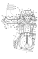
- FIG. 1 is a schematic configuration diagram of an internal combustion engine according to a first embodiment of the present invention.
- FIG. 2 is a front view of a three-dimensional model from a part of the intake passage to an exhaust port of the internal combustion engine of FIG.
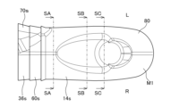
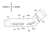
- FIG. 3 is a plan view of a three-dimensional model of the downstream side of the intake passage of the internal combustion engine of FIG.
- FIG. 4 is a front view of the three-dimensional model of FIG.
- FIG. 5 is a bottom view of the three-dimensional model of FIG.
- FIG. 6 is a rear view of the three-dimensional model of FIG.
- FIG. 7 is a left side view of the three-dimensional model of FIG.
- FIG. 8 is a right side view of the three-dimensional model of FIG. FIG.
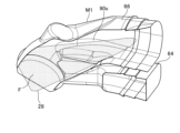
- FIG. 9 is a perspective view from the left side of the three-dimensional model of FIG.
- FIG. 10 is a perspective view of the three-dimensional model of FIG. 3 from the right side.
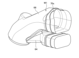
- FIG. 11 is a perspective view of the three-dimensional model shown in FIG. 6, and is a diagram showing a schematic diagram of the sprayed fuel injected from the fuel injection valve.
- FIG. 12 is a perspective view of the three-dimensional model shown in FIG. 3, which diagrammatically illustrates the sprayed fuel injected from the fuel injector, similar to that shown in FIG.
- FIG. 13 is a cross-sectional view taken along the intake air flow direction of the three-dimensional model of FIG. 3, and shows, in a schematic manner, the sprayed fuel injected from the fuel injector, similar to that shown in FIG. FIG.
- FIG. 14A is a cross-sectional view of the three-dimensional model of FIG. 3 having sprayed fuel injected from a fuel injector similar to that shown in FIG. 11, taken along line SA-SA in FIG.
- FIG. 14B is a cross-sectional view of the three-dimensional model of FIG. 3 having sprayed fuel injected from a fuel injector similar to that shown in FIG. 11, taken along the line SB-SB in FIG. 14C is a cross-sectional view of the three-dimensional model of FIG. 3 having sprayed fuel injected from a fuel injector similar to that shown in FIG. 11, taken along line SC-SC in FIG.
- FIG. 15A is a perspective view of a portion of the three-dimensional model shown in FIG. 14A.
- FIG. 15B is a perspective view of a portion of the solid model shown in FIG. 14B.
- FIG. 15C is a perspective view of a portion of the solid model shown in FIG. 14C.
- FIG. 16 is a perspective view of a three-dimensional model of the intake passage of the internal combustion engine of FIG.
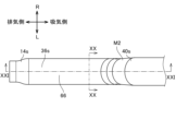
- FIG. 17 is a front view of the three-dimensional model of FIG.
- FIG. 18 is a bottom view of the three-dimensional model of FIG.
- FIG. 19 is a plan view of the three-dimensional model of FIG.
- FIG. 20 is a cross-sectional view taken along line XX-XX of the three-dimensional model of FIG.
- FIG. 21 is a cross-sectional view taken along line XXI-XXI of the three-dimensional model of FIG.
- FIG. 22 is a schematic diagram of the cross-sectional view of FIG.
- FIG. 23 is a front view of a three-dimensional model of an intake passage of an internal combustion engine according to the second embodiment.
- FIG. 24 is a schematic diagram of the intake passage of FIG.
- FIG. 25 is a front view showing a modified example of the intake passage of the internal combustion engine according to the second embodiment.
- FIG. 26 is a perspective view of a three-dimensional model of an intake passage of an internal combustion engine according to the third embodiment.
- FIG. 27 is a front view of the three-dimensional model of FIG.
- FIG. FIG. 30 shows the results of a computer simulation.
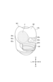
- FIG. 1 is a cross-sectional view of the internal combustion engine 10 taken along the axis (cylinder axis) C of the cylinder bore 12b of the cylinder block 12 of the internal combustion engine 10.
- the internal combustion engine 10 is a single-cylinder engine, but the internal combustion engine to which the present invention is applied is not limited to a single-cylinder engine and may be a multi-cylinder engine.
- the piston 15 that reciprocates within the cylinder bore 12b of the cylinder block 12 is connected to the crank pin of the crankshaft 17 of the crankcase portion 16 by a connecting rod 18.
- a combustion chamber 20 is formed between the top surface 15a of the piston 15 that is slidably fitted within the cylinder bore 12b of the cylinder block 12 and the combustion chamber ceiling surface 14a of the cylinder head 14 that the top surface 15a faces.
- the internal combustion engine 10 employs a two-valve system of the SOHC type, and the cylinder head 14 is provided with a valve train 22.
- a cylinder head cover 24 is placed over the cylinder head 14 to cover the valve train 22.
- an endless cam chain (not shown) is installed between the camshaft 26 and the crankshaft 17, passing through a cam chain chamber (not shown) provided on one side of the crankshaft direction of the crankcase 16, the cylinder block 12, and the cylinder head 14, and the camshaft 26 rotates in synchronization with the crankshaft 17 at half the rotational speed.
- An ignition plug is inserted into the cylinder head 14 from the opposite side of the cam chain chamber (the other side in the crankshaft direction) toward the combustion chamber 20.
- the intake port 32 and exhaust port 34 are formed by extending from the intake valve port 28 and exhaust valve port 30, which open into the combustion chamber ceiling surface 14a, while curving upward and downward away from each other. As described above, a two-valve system is used, and a single intake port 32 and a single exhaust port 34 are defined in the cylinder head 14.
- the upstream end of the intake port 32 opens toward the top of the cylinder head 14 and connects to an inlet pipe 36 to form a continuous intake passage 38, and a throttle body 40 is connected to the upstream side of the inlet pipe 36.
- the downstream end of the exhaust port 34 opens toward the bottom of the cylinder head 14 and is connected to an exhaust pipe 42.
- An exhaust purification device and a silencer can be provided downstream of the exhaust pipe 42.
- a cylindrical intake valve guide 44 is fitted integrally to the curved outer wall portion 32a of the intake port 32 in the cylinder head 14.
- An intake valve 46 slidably supported by the intake valve guide 44 opens and closes the intake valve opening 28 of the intake port 32 facing the combustion chamber 20.
- an exhaust valve 50 slidably supported by an exhaust valve guide 48 that is integrally fitted to the curved outer wall portion 34a of the exhaust port 34 in the cylinder head 14 opens and closes the exhaust valve opening 30 of the exhaust port 34 facing the combustion chamber 20.
- the intake valve 46 and exhaust valve 50 have their head portions 46a, 50a biased upward by valve springs so as to close the intake valve port 28 and exhaust valve port 30 that face the combustion chamber 20.
- the stem ends 46b, 50b of the intake valve 46 and exhaust valve 50 are pushed down by the intake rocker arm 56 and exhaust rocker arm 58, which swing against the intake cam and exhaust cam of the camshaft 26, opening the intake valve 46 and exhaust valve 50 at a predetermined timing, connecting the intake port 32 and the combustion chamber 20, and connecting the exhaust port 34 and the combustion chamber 20, and allowing intake and exhaust to occur at a predetermined timing.
- An inlet pipe 36 is connected to the upstream end of the intake port 32 of the internal combustion engine 10 via an insulator 60 to form a continuous intake passage 38, and a throttle body 40 is connected to the upstream side of the inlet pipe 36.
- the throttle body 40 has an intake passage 40a with a roughly circular cross section that forms part of the intake passage 38 that leads to the combustion chamber 20 of the internal combustion engine 10, and its upstream side is connected to an air cleaner device (not shown).
- the throttle body 40 is rotatably supported within the throttle body 40 by a throttle valve shaft 40b that intersects perpendicularly to the flow direction of the intake air in the intake passage 40a, i.e., at a right angle to the central axis of the intake passage 40a, and is equipped with a throttle valve 40c that can variably control the flow area of the intake passage 40a and open and close the intake passage 40a.
- the throttle valve 40c is of the butterfly type and has a throttle valve shaft 40b and a disk-shaped valve body 40d that is fixed to the throttle valve shaft 40b and rotates integrally therewith.
- the throttle valve 40c can be rotated in the opening direction (counterclockwise in FIG. 1) by the driver's operation, etc., and the valve body 40d is biased in the closing direction (clockwise) by a return spring (not shown) so that the valve body 40d is positioned in the fully closed position where its edge abuts against the inner wall surface of the intake passage 40a.
- an intake structure S is configured to provide a tumble vortex, i.e., tumble flow, i.e., vertical rotation, of the fuel-air mixture in the combustion chamber 20.
- the intake structure S includes a partition 62 provided in the intake passage 38.
- the partition 62 is provided in the intake passage 38 so as to divide the intake passage 38 into a plurality of passages in the direction of the cylinder axis C.
- the intake passage 38 is divided along the intake flow direction by the partition 62 continuing from the inlet pipe 36 to the intake port 32, and is divided into a tumble flow passage 64 configured so that the intake air that passes through generates a tumble flow in the combustion chamber 20, and a main flow passage 66 excluding the tumble flow passage 64.
- the tumble flow passage 64 corresponds to the first intake passage
- the main flow passage 66 corresponds to the second intake passage.
- the tumble passage 64 may also be referred to as a secondary passage.
- the partition 62 which extends like a plate in the intake flow direction, is provided so as to substantially extend substantially parallel to the axis extending in the flow direction, so as to substantially divide the downstream side of the intake passage 38 in the vertical direction.
- the flow path cross-sectional area of the tumble flow path 64 is smaller than the flow path cross-sectional area of the main flow path 66.
- the partition 62 may be provided so that the flow path cross-sectional area of the tumble flow path 64 is larger than the flow path cross-sectional area of the main flow path 66, and it is also possible to make them substantially the same.
- the lower part of the intake passage 38 separated by the partition 62 becomes the tumble passage 64, and the upper part becomes the main passage 66, but in this specification they are not limited to being arranged up and down.
- “up” and “down” with respect to the intake passage 38, etc. refer to the direction from the crankshaft 17 side to the cylinder head 14 or cylinder head cover 24 side in the direction of the cylinder axis C as “up” or “upper” direction, and the direction opposite to this "up” direction, that is, the direction from the cylinder head 14 side to the crankshaft 17 side as “down” or “downer” direction, and do not mean absolute “up” and "down” in space.
- the internal combustion engine 10 is provided with a fuel injection valve 70.
- the fuel injection valve 70 is provided to inject fuel into the intake port 32.
- the fuel injection valve 70 is provided to face the main flow passage 66, and is provided in the inlet pipe 36 here. In this manner, the fuel injection valve 70 is provided to inject fuel from the main flow passage 66 side and supply fuel to the combustion chamber 20 via the intake port 32.
- the fuel injection valve 70 is attached to the upper wall of the member that defines the intake passage 38.
- the present disclosure does not limit the number of fuel injection valves to one, and may be, for example, two.
- a second fuel injection valve may be provided to inject fuel into the portion of the intake passage 38 upstream of the partition 62.
- the ECU (electronic control unit) 72 that controls the internal combustion engine 10 has a so-called computer configuration, and includes an intake control unit 74 and a fuel injection control unit 76. That is, the ECU 72 includes a processor (e.g., a CPU) and memory (e.g., a ROM and a RAM). The ECU 72 analyzes the operating state of the internal combustion engine 10 based on the output from various sensors such as an engine speed sensor and an engine load sensor, and controls the operation of the throttle valve 40c using the intake control unit 74. The ECU 72 also controls the operation of the fuel injection valve 70 using the fuel injection control unit 76 based on the analyzed operating state of the internal combustion engine 10. The ECU 72 stores programs and various data for these controls.
- the throttle valve 40c is electronically controlled here, but is not limited to being electronically controlled, and may be a valve that is mechanically controlled by a throttle cable, for example.
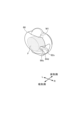
- the 2 shows a three-dimensional model M of the internal combustion engine 10, from the intake passage 38 shown in FIG. 1 through the combustion chamber 20 to the exhaust port 34.
- the three-dimensional model M includes the intake passage 40a of the throttle body 40 to the exhaust port 34.
- This three-dimensional model M has the characteristic configuration of the intake structure S of the internal combustion engine 10.
- the intake structure S of the internal combustion engine 10 is configured to have a curved portion 100 and a communicating portion 102 provided in relation to the partition portion 62. Below, first, the configuration of the intake structure S other than the curved portion 100 and the communicating portion 102 will be mainly described, and then the curved portion 100 and the communicating portion 102 will be described.
- the three-dimensional model M1 includes the intake port 32 from the downstream end of the inlet pipe 36, and terminates at the intake valve port 28 on the downstream side. Since the three-dimensional model M1 is a model of the downstream end of the intake passage 38, the outer surface 80 of the three-dimensional model M1 has a portion corresponding to the inner surface 36s of the inlet pipe 36, the inner surface 60s of the insulator 60, and the inner wall surface 14s of the cylinder head 14, which are members that define the downstream side of the intake passage 38, and a portion corresponds to the surface 62s of the partition portion 62, and a portion corresponds to the surface 90s of the offset portion 90, which will be described later.
- the parts of the three-dimensional model M1 that correspond to the inner surface 36s of the inlet pipe 36, the inner surface 60s of the insulator 60, the inner wall surface 14s of the cylinder head 14, the surface 62s of the partition portion 62, and the surface 90s of the offset portion 90 are given their respective reference numerals. Additionally, the portion where the fuel injection valve 70 is attached and where its nozzle faces the intake passage 38 (hereinafter referred to as the attachment portion) is given the symbol "70s".
- the symbol “U” is used for the upper side in the direction of the cylinder axis C
- the symbol “D” is used for the lower side
- the symbol “R” is used for the right side when viewed from upstream to downstream in the intake flow direction
- the symbol “L” is used for the left side.
- the partition 62 has a deviation portion 90 on its downstream side, which has a narrower width in the left-right direction (L-R direction) intersecting the cylinder axis C, i.e., in the width direction, than other portions such as the upstream end (upstream end) 62u of the partition 62.
- the deviation portion 90 is a narrow portion of the partition 62 in a width direction that can be defined as a direction extending from one side of the valve axis of the intake valve 46 to the other side when the intake air flows from the upstream side to the downstream side in the intake passage 38, i.e., in the intake flow direction, toward the intake valve 46. As shown in FIG.
- the width W2 in the downstream end portion 64d in the width direction is clearly narrower than the width W1 in the width direction of the upstream end portion 62u' located on the upstream end 62u side of the partition 62 among the portions partitioned and formed by the cylinder head 14.
- the partition 62 is provided and formed to define the tumble flow passage 64 in the intake passage 38, so the offset portion 90 with respect to this portion of width W2 is relatively narrow.
- the deviation portion 90 is biased in one direction in the left-right direction, i.e., the width direction.
- the downstream end portion 64d of the tumble flow path 64 is defined so as to be biased toward the right R side. Therefore, the deviation portion 90 downstream of the partition portion 62 that at least partially defines the biased downstream end portion 64d of the tumble flow path 64 is biased toward the right R side here. Therefore, in FIG. 1, the cylinder axis C extends parallel to the paper surface, and the width direction extends approximately perpendicular to the paper surface, so the deviation portion 90 extending downstream of the partition portion 62 does not appear, and is therefore shown by a two-dot dashed line instead of a solid line.
- the mounting portion 70s of the fuel injection valve 70 is positioned on the left L side of the intake passage 38.
- the fuel injection valve 70 is provided at a position offset in a direction opposite to the offset direction of the offset portion 90.
- the fuel injection valve 70 is provided so as to be able to inject fuel in a direction different from the offset direction of the offset portion 90, more preferably in the opposite direction.
- the fuel injection valve 70 is provided on the upper side, i.e., on the main flow path 66 side, and injects fuel from the main flow path 66 side.
- FIG. 11 which is a perspective view of the three-dimensional model M1 shown in FIG. 6, shows a schematic representation of the sprayed fuel F injected from the fuel injection valve 70, which is disposed at a position offset to the left L side.
- FIG. 12 shows a perspective view of the three-dimensional model M1, which shows a schematic representation of the sprayed fuel F injected from the fuel injection valve, similar to that shown in FIG. 11.
- FIG. 13 shows a cross-sectional view of the three-dimensional model M along the intake flow direction, which shows a schematic representation of the sprayed fuel F injected from the fuel injection valve 70, similar to that shown in FIG. 11. From FIG. 11 to FIG.
- the fuel F injected from the fuel injection valve 70 flows at least partly, particularly at least half of the fuel, and more preferably all of the fuel, without being blocked by the partition 62, first through the main flow passage 66, then through the junction of the main flow passage 66 and the tumble flow passage 64, and then directly reaches the intake valve port 28 and is introduced into the combustion chamber 20.
- the arrangement of the fuel injection valve 70 and the shape of the partition 62 including the offset portion 90 are designed to enable such fuel injection.
- the partition body portion 92 of the partition 62 terminates downstream to enable the main flow path 66 and the tumble flow path 64 to merge, and the partition body portion 92 and offset portion 90 of the partition 62 are designed so that the fuel F injected from the fuel injection valve 70 reaches the intake valve port 28 along the surface 90s of the offset portion 90, preferably without touching the offset portion 90 (see, for example, FIG. 12).
- FIG. 14A is a cross-sectional view of the three-dimensional model M1 at a position along the SA-SA line in FIG. 3
- FIG. 14B is a cross-sectional view of the three-dimensional model M1 at a position along the SB-SB line in FIG. 3
- FIG. 14C is a cross-sectional view of the three-dimensional model M1 at a position along the SC-SC line in FIG. 3.
- FIG. 15A is a perspective view of a portion of the three-dimensional model M1 in FIG. 14A
- FIG. 15B is a perspective view of a portion of the three-dimensional model M1 in FIG. 14B
- FIG. 15C is a perspective view of a portion of the three-dimensional model M1 in FIG. 14C.
- the tumble flow path 64 and the main flow path 66 are completely separated.
- the partition 62 extends to the inner surface 36s of the inlet pipe 36 at both ends in the width direction between the tumble flow path 64 and the main flow path 66, and the partition body 92 that connects to the upstream side of the deviation section 90 extends.
- the surface 62s of the partition 62 and the surface 92s of the partition body 92 therein are denoted by the same reference numerals.
- the tumble flow passage 64 and the main flow passage 66 are partially connected. Also, in the cut surfaces of FIGS. 14B and 15B, the surface 62s of the partition 62 extends in the width direction as well as in the vertical direction, and is biased to the right. From this, it can be seen that at the position of line SB-SB in FIG. 3, the partition 62 transitions from the partition main body 92 to the offset portion 90, and the offset portion 90 extends leftward from the right side of the inner wall surface 14s of the cylinder head 14 to the intake port 32, to the extent that it does not completely separate the tumble flow passage 64 and the main flow passage 66.
- the tumble flow passage 64 and the main flow passage 66 are partitioned so that the main flow passage 66 and the tumble flow passage 64 are connected in the region where the offset portion 90 extends in the intake flow direction.
- the offset portion 90 connected to the partition body portion 92 is formed to extend downstream of the partition body portion 92 so that a portion of the partition body portion 92 of the partition portion 62 is extended in the flow direction downstream of the partition body portion 92.
- the parts corresponding to the surface 62s of the partition portion 62 and the surface 90s of the offset portion 90 thereon are given the same reference numerals, and this is also true in Figures 14C and 15C.
- the amount of leftward protrusion of the deviation portion 90 from the inner wall surface 14s of the cylinder head 14 is reduced compared to the cut portions of FIGS. 14B and 15B.
- the deviation portion 90 is formed so as to become narrower toward the downstream side in the intake flow direction.
- the degree of communication between the main flow passage 66 and the tumble flow passage 64 is greater at the cut portions of FIGS. 14C and 15C than at the cut portions of FIGS. 14B and 15B.
- the amount of connection between the tumble flow passage 64 and the main flow passage 66 at the cut positions of FIGS. 14C and 15C is greater than the amount of connection between them at the cut positions of FIGS. 14B and 15B.
- the tumble flow passage 64 and the main flow passage 66 are partitioned so that the main flow passage 66 extends downward to the side of the deviation portion 90 in the region where the deviation portion 90 extends in the intake flow direction.
- This downward expansion of the main flow path 66 is performed in the direction opposite to the direction in which the deviation section 90 is biased, and in this case, it is performed on the left L side of the deviation section 90. Note that this downward expansion of the main flow path 66 and the resulting merging of the main flow path 66 and the tumble flow path 64 are more noticeable downstream of the deviation section 90.
- the fuel injection valve 70 which is arranged to inject fuel F from the main flow passage 66 toward the combustion chamber 20, is arranged to inject fuel in the direction opposite to the biased direction of the deviation portion 90. Therefore, the partition portion 62, and in particular the deviation portion 90, can be extended further downstream in the intake flow direction.
- the tumble flow passage 64 is then partitioned and formed so that it is biased downstream in the biased direction of the deviation portion 90. Therefore, the deviation portion 90 of the partition portion 62, which is extended further downstream in the intake flow direction, can impart stronger directionality to the intake air from the tumble flow passage 64.
- the partition 62 is designed to completely separate the main flow path 66 and the tumble flow path 64 with the partition body 92 on the upstream side, and to have the offset portion 90 on the downstream side, so that the flow from the tumble flow path 64 is characterized further downstream while realizing the connection between the main flow path 66 and the tumble flow path 64.
- the fuel injection valve 70 is arranged in a biased position opposite to the bias of the offset portion 90, and here, it is arranged on the opposite side in the width direction, so that it can inject fuel in a direction different from the offset portion 90, and can introduce fuel into the combustion chamber 20 almost directly through the intake valve port 28. In other words, the supply of fuel to the combustion chamber can be well ensured.
- the offset portion 90 which is the downstream portion of the partition 62, can be extended further downstream. Therefore, it is possible to give a stronger directionality to the flow from the tumble flow path 64.
- This directionality is directed between the intake valve port 28 and the umbrella portion 46a of the intake valve 46 when the valve is open so as to form a stronger tumble flow in the combustion chamber 20, so that the intake air from the tumble flow passage 64 can more suitably form a tumble flow in the combustion chamber 20.
- the tumble flow passage 64 and the main flow passage 66 are partitioned so that the tumble flow passage 64 communicates with the main flow passage 66 downstream of the downstream edge of the partition portion 62, i.e., the downstream edge 90d of the offset portion 90, and forms a single intake passage leading to the combustion chamber 20.
- This allows intake air from the tumble flow passage 64 to be introduced into the combustion chamber 20 together with intake air from the main flow passage 66, making it possible to supply fuel to the combustion chamber 20 and form a tumble flow with intake air from the single intake port 32, which is a single intake passage.
- This configuration also makes it possible to suppress an increase in the number of parts, and is also excellent in terms of cost.
- the intake structure S of the internal combustion engine 10 includes a curved portion 100 and a communicating portion 102 (FIGS. 1 and 2).
- the curved portion 100 is provided immediately downstream of the throttle valve 40c.
- the curved portion 100 is part of the intake passage 38, and is a portion that is bent in a substantially V-shape.
- the communicating portion 102 is formed at a location of the partition portion 62 downstream of the curved portion 100.
- the communication portion 102 communicates the tumble flow passage 64 and the main flow passage 66 at the partition portion 62 provided in the intake passage 38 connected to the combustion chamber 20 so as to separate the tumble flow passage 64 and the main flow passage 66.
- the communication portion 102 may be called a gap, a hole, an opening, or the like.
- the communication portion 102 extends from one end to the other end of the partition portion 62 in a direction perpendicular to the intake flow direction, in other words, it is a long and narrow hole that extends to the inner surface 36s of the inlet pipe 36 at both ends in the width direction.
- the communication portion 102 divides the partition portion 62 into an upstream partition portion 62a located upstream of the communication portion 102 and a downstream partition portion 62b located downstream of the communication portion 102.
- the communication portion 102 is a gap portion between the upstream partition portion 62a and the downstream partition portion 62b. Note that the configuration described above based on Figures 3 to 15C relates to the downstream partition section 62b.
- a three-dimensional model M2 from the throttle valve 40c of the intake passage 38 to the partition portion 62 is shown in Figs. 16 to 21.
- Fig. 16 is a perspective view of the three-dimensional model M2
- Fig. 17 is a front view of the three-dimensional model M2
- Fig. 18 is a bottom view of the three-dimensional model M2
- Fig. 19 is a plan view of the three-dimensional model M2
- Fig. 20 is a cross-sectional view of the three-dimensional model M2 in Fig. 19 taken along line XX-XX
- Fig. 21 is a cross-sectional view of the three-dimensional model M2 in Fig. 19 taken along line XXI-XXI.
- insulator 60, mounting portion 70s of fuel injection valve 70, and offset portion 90 are omitted for ease of explanation, and the downstream end of downstream side partition portion 62b of partition portion 62 is shown as terminating at partition main body portion 92, but this does not exclude, for example, that offset portion 90 is provided at the downstream end of partition main body portion 92.
- the partition body 92 is a portion that extends from the upstream partition 62a to the downstream partition 62b.
- the parts of the three-dimensional model M2 that correspond to, for example, the inner surface 36s of the inlet pipe 36, the inner wall surface 14s of the cylinder head 14, the inner wall surface 40s that defines the intake passage 40a of the throttle body 40, the surface 62s of the partition 62, the surface 62as of the upstream partition 62a, and the surface 62bs of the downstream partition 62b are given their respective reference numerals.
- the curved portion 100 is provided upstream of the communicating portion 102.
- the curved portion 100 is formed so that the communicating portion 102 is located on an extension of the flow of intake air that has flowed into the main flow passage 66.
- the intake passage that connects to the upstream side of the curved portion 100 is the intake passage 40a of the throttle body 40 in this case, the curved portion 100 is formed so that when a straight line IL (see Figure 1) parallel to the axis 40AX of the intake passage 40a is defined, the curved portion 100 is formed so that the straight line IL passes through the intake passage 40a and extends from the main flow passage 66 to the tumble flow passage 64 via the communicating portion 102. More specifically, in Fig.
- This straight line L1 is an example of a straight line IL parallel to the axis 40AX of the intake passage 40a.
- the curved inner surface 106 of the inner circumferential surface 104 is the inner part in the curved direction of the curved portion 100, and the curved outer surface 108 of the inner circumferential surface 104 is the outer part in the curved direction of the curved portion 100. Therefore, the tumble flow path 64 is located on the outer side of the curve in the curved portion 100 than the main flow path 66.
- FIG. 21 which is also a cross section of the partition 62 cut in the vertical direction, the line L1 extends directly to the communication portion 102.
- the line L1 which extends so as to deviate at the curved inner surface 106, passes through the main flow path 66, passes through the communication portion 102, and extends to the tumble flow path 64.
- the upstream end of the partition 62 i.e., the upstream partition 62a, curves toward the throttle valve 40c along the curved shape of the curved portion 100.
- This upstream partition 62a should preferably extend to a position closer to the throttle valve 40c, but is not limited to this and can be designed in various ways.
- the curved inner surface 106 of the curved portion 100 has a protrusion 110 having a radius of curvature R2 (R1>R2) smaller than the radius of curvature R1 of the curved inner surface 106.
- the protrusion 110 protrudes toward the intake passage 38 on the curved inner surface 106, as shown in FIG. 21 in particular.
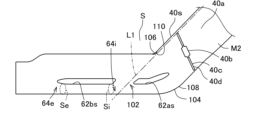
- the tumble flow passage 64 is partitioned so that the cross-sectional area Se of the downstream outlet section 64e of the tumble flow passage 64 is smaller than the cross-sectional area Si at the downstream end section 64i of the communication section 102, i.e., the cross-sectional area Si at the upstream end of the downstream partition section 62b (Se ⁇ Si). Note that the difference between the cross-sectional area Se and the cross-sectional area Si may be slight.
- the curved portion 100 is formed so that when a straight line IL parallel to the axis 40AX of the intake passage 40a connected to the upstream side of the curved portion 100 is defined, the straight line IL passes through the intake passage 40a and extends from the main passage 66 to the tumble passage 64 via the communication portion 102.
- the schematic diagram in Figure 22 is a schematic diagram of the cross-sectional view in Figure 21, and like Figures 16 to 21, the tumble valve 40c is opened to a small opening.
- the intake air that passes through the opening 40e on the curved outer surface 108 side of the curved portion 100 of the tumble valve 40c flows toward the lower side of the upstream partition portion 62a and can flow into the tumble flow path 64.
- the intake air that passes through the opening 40f on the curved inner surface 106 side of the curved portion 100 of the tumble valve 40c flows toward the upper side of the upstream partition portion 62a and can flow into the main flow path 66.
- the curved portion 100 is formed so that a straight line IL parallel to the axis 40AX of the intake passage 40a connected to the upstream side of the curved portion 100 passes through the intake passage 40a and extends from the main flow passage 66 to the tumble flow passage 64 via the communicating portion 102.
- the curved portion 100 of the intake passage 38 provided upstream of the communicating portion 102 is formed so that the communicating portion 102 is located on an extension line of the flow of the intake air that has flowed into the main flow passage 66.
- the intake air that has passed through the opening 40f on the curved inner surface 106 side flows into the main flow passage 66 so as to be separated at the curved inner surface 106 of the curved portion 100, and can directly reach the communicating portion 102 as it is. Therefore, the intake air that has flowed into the main flow passage 66 can be actively guided to the tumble flow passage 64, and can be merged with the intake air that has passed through the opening 40e on the curved outer surface 108 side in the tumble flow passage 64.
- the flow of intake air into the tumble passage 64 through the communication portion 102 can occur not only when the tumble valve 40c is opened to a small degree as shown in Figures 21 and 22, but also when the tumble valve 40c is opened to a large degree.
- the intake structure S of the internal combustion engine 10 it is possible to relatively increase the proportion of intake air flowing through the tumble passage 64 in a wider operating range while suppressing an increase in the number of parts of the internal combustion engine, since it is not necessary to provide a tumble control valve, for example, and therefore it is possible to more suitably promote the generation of vortexes such as tumble vortexes in the combustion chamber 20.
- the tumble flow passage 64 is located on the outer side of the curve in the curved portion 100 than the main flow passage 66. Therefore, by generating a flow of intake air from the main flow passage 66 to the tumble flow passage 64 via the communication portion 102, more intake air can be made to flow into the tumble flow passage 64, and a tumble flow can be more suitably generated in the combustion chamber 20.
- a throttle valve 40c is provided upstream of the curved portion 100, and the upstream end 62u of the partition portion 62 curves toward the throttle valve 40c along the curved shape of the curved portion 100, as shown in Figures 1 and 21, for example. Therefore, the intake air that passes through the opening 40e on the tumble flow passage 64 side of the throttle valve 40c is more likely to flow into the tumble flow passage 64, making it possible to more reliably ensure the amount of intake air flowing through the tumble flow passage 64.
- the curved inner surface 106 of the curved portion 100 has a protrusion 110 with a radius of curvature smaller than the radius of curvature of the curved inner surface 106. Therefore, the intake air that has passed through the opening 40f on the curved inner surface 106 side of the curved portion 100 of the throttle valve 40c can be more effectively encouraged to separate at the curved inner surface 106 of the curved portion 100. This makes it possible to more actively encourage the flow of intake air from the main flow path 66 to the tumble flow path 64, thereby making it possible to, for example, increase the amount of intake air flowing from the main flow path 66 to the tumble flow path 64.
- the tumble flow passage 64 is partitioned so that the cross-sectional area Se of the downstream outlet portion 64e of the tumble flow passage 64 is smaller than the cross-sectional area Si at the downstream end portion 64i of the communication portion 102, i.e., the cross-sectional area Si at the upstream end of the downstream partition portion 62b (Se ⁇ Si).
- the line corresponding to the cross-sectional area Se is marked with the symbol "Se”
- the line corresponding to the cross-sectional area Si is marked with the symbol "Si”.
- the ratio of the cross-sectional area Se of the downstream outlet portion 64e of the tumble flow passage 64 to the cross-sectional area Si at the downstream end portion 64i of the communication portion 102 can be set in various ways, but it is preferable that it is, for example, about 14:about 15.
- the curved angle ⁇ (see FIG. 22) of the curved portion 100 can be set in various ways.
- the curved angle ⁇ is the intersection angle between a line L2 (here, this line L2 is the center line in the intake flow direction) that is determined to extend in the intake passage portion 38a where the communication portion 102 is located, and a line L3 that is determined to extend in the intake flow direction through the valve shaft 40b of the throttle body 40, that is, the axis 40AX of the intake passage 40a.
- the curved angle ⁇ is about 25°, but it may be an angle greater than 25°, such as 30°, 40°, or 45°.
- the curved angle ⁇ may be an angle of 20° to 50°, preferably in the range of 25° to 45°, but may be set according to the characteristics or specifications of the internal combustion engine 10.
- FIG. 23 is a front view of a three-dimensional model M3 of the intake passage of the internal combustion engine according to the second embodiment, and corresponds to FIG. 17 of the internal combustion engine 10 according to the first embodiment.
- FIG. 24 is a schematic diagram of the intake passage of the internal combustion engine according to the second embodiment, and corresponds to FIG. 22 of the internal combustion engine 10 according to the first embodiment.
- This internal combustion engine has substantially the same configuration as the internal combustion engine 10, and differs in that the intake structure S1 does not have the protrusion 106, but has a protrusion 112.
- the protrusion 112 is formed so as to extend toward the main flow path 66 at the downstream end 102d of the communication portion 102 of the partition portion 62.
- the portion corresponding to the surface 112s of the protrusion 112 is marked with the symbol "112s".
- the protrusion 112 is formed as the upstream end 62bu of the downstream partition portion 62b (see FIG. 24).
- the protrusion 112 extends toward the main flow path 66 and upstream at the upstream end 62bu of the downstream partition portion 62b, partially covering the communication portion 102 from the main flow path 66 side.
- the protrusion 112 is provided so as to protrude from the upstream end 62bu of the downstream partition portion 62 of the partition portion 62, but may be discontinuous with the downstream partition portion 62b of the partition portion 62.
- the downstream end 102d of the communication section 102 of the partition section 62 is formed with a protrusion 112 extending toward the main flow path 66, making it easier to direct a portion of the intake air flowing through the main flow path 66 toward the tumble flow path 64.
- a protrusion 112 it becomes possible to more actively prevent a portion of the intake air flowing through the tumble flow path 64 from being directed toward the main flow path 66.
- the intake passage 38 may be curved further in the middle of the inlet pipe 36. This allows for greater freedom in installation on the vehicle.
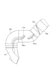
- Fig. 26 is a perspective view of a three-dimensional model M4 of the intake passage of the internal combustion engine according to the third embodiment
- Fig. 27 is a front view of the three-dimensional model M4
- Fig. 28 is a plan view of the three-dimensional model M4
- Fig. 29 is a cross-sectional view of the three-dimensional model M4 taken along line XXIX-XXIX in Figs. 27 and 28, which corresponds to Fig. 20 of the internal combustion engine 10 according to the first embodiment.
- the intake structure S2 of this internal combustion engine differs from the intake structure S of the internal combustion engine according to the first embodiment described above in that it does not include a protrusion 106 and in the cross-sectional shape of the intake passage 38. However, this does not exclude the intake structure S2 of the internal combustion engine from further including the above-mentioned protrusion 106, and the intake structure S2 of the internal combustion engine can further include a protrusion 106.
- the intake structure S2 of the internal combustion engine according to the third embodiment i.e., the three-dimensional model M4 of the intake passage, can also be provided with the protrusion 112 that provides the above-mentioned effects.
- the differences will be mainly described, and the same reference numerals will be used for components that correspond to those already described, and duplicate descriptions will be omitted as much as possible.
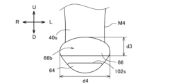
- the passage portion 66b downstream of the curved portion 100 in the main flow path 66 and upstream of the communicating portion 102 has a shape that is squashed vertically without changing the cross-sectional area, compared to the passage portion 66ba (see Figures 17 and 20) of the intake structure S of the internal combustion engine 10 described above.
- the passage portion 66b downstream of the curved portion 100 in the main flow path 66 and upstream of the communicating portion 102 is shaped so that it is shorter in length in the vertical direction (U-D direction in Figure 27), which is the first direction connecting the tumble flow path 64 and the main flow path 66, and longer in length in the width direction (left-right direction, i.e., L-R direction in Figure 28), which is the second direction perpendicular to the first direction, compared to the passage portion 66ba of the internal combustion engine 10 in the first embodiment, in which the cross-sectional shape of the intake passage 38 in the passage portion 66b is circular.
- U-D direction in Figure 27 the first direction connecting the tumble flow path 64 and the main flow path 66
- L-R direction in Figure 28 left-right direction, i.e., L-R direction in Figure 28
- the length of the intake flow path (corresponding to distance d5 in FIG. 27) that passes through the curved portion 100 and flows from the main flow path 66 into the tumble flow path 64 via the communication portion 102 can be made relatively shorter compared to that in the intake structure S of the internal combustion engine 10 of the first embodiment. Therefore, the intake air can be guided from the main flow path 66 to the tumble flow path 64 via the communication portion 102 over a shorter distance without impairing the strength of the flow, making it possible to impart a stronger flow to the flow in the tumble flow path 64.
- the above-mentioned features of the intake structure S2 of the internal combustion engine according to the third embodiment can be applied to the intake structure S of the internal combustion engine according to the first embodiment and the intake structure S1 of the internal combustion engine according to the second embodiment, and can provide similar effects.
- FIG. 30 shows the results of a computer simulation of the intake structure S of the internal combustion engine 10 with the throttle valve 40c opened to a small opening.
- the intake air that passed through the opening 40e on the curved outer surface 108 side of the curved portion 100 of the tumble valve 40c flows toward the lower side of the upstream partition 62a and enters the tumble flow passage 64.
- the intake air that passed through the opening 40f on the curved inner surface 106 side of the curved portion 100 of the tumble valve 40c flows toward the upper side of the upstream partition 62a, flows into the main flow passage 66 so as to be separated at the curved inner surface 106 of the curved portion 100, and directly reaches the communication portion 102 and merges with the intake air in the tumble flow passage 64.
- the same results were obtained when the opening of the throttle valve 40c was made larger.
- the intake structure S of the internal combustion engine of the first embodiment, the intake structure S1 of the internal combustion engine of the second embodiment, and the intake structure S2 of the internal combustion engine of the third embodiment can be combined with each other in whole or in part as long as no technical contradiction arises.
- the tumble flow passage 64 is located on the outer side of the curved portion 100, and the main flow passage 66 is located on the inner side of the curved portion 100, but the present invention does not exclude the reverse of this relationship. However, preferably, the tumble flow passage 64 is located on the outer side of the curved portion 100 than the main flow passage 66.
Landscapes
- Engineering & Computer Science (AREA)
- Chemical & Material Sciences (AREA)
- Combustion & Propulsion (AREA)
- Mechanical Engineering (AREA)
- General Engineering & Computer Science (AREA)
- Cylinder Crankcases Of Internal Combustion Engines (AREA)
Abstract
本開示は、内燃機関の部品点数の増加を抑制しつつ、より広い運転領域で燃焼室での渦流の生成を促すことを可能にする構成を提供することに向けられている。一実施形態に係る内燃機関の吸気構造Sは、燃焼室20に連なる吸気通路38に第1吸気通路64と第2吸気通路66とを隔てるように設けられる仕切部62であって、前記第1吸気通路64と前記第2吸気通路66とを連通させる連通部102を有する仕切部62と、前記連通部102よりも上流側に設けられる前記吸気通路38の湾曲部100とを備える。前記湾曲部100の上流側につながる吸気路40aの軸線40AXに平行な直線ILを定めるとき、前記直線ILが前記吸気路40a内を通り、前記第2吸気通路66から前記連通部102を介して前記第1吸気通路64に延びるように、前記湾曲部100は形成されている。
Description
本発明は、燃焼室に連なる吸気通路に仕切部を備える内燃機関の吸気構造に関する。
近年、より多くの人々が手ごろで信頼でき、持続可能かつ先進的なエネルギーへのアクセスを確保できるようにするため、エネルギーの効率化に貢献する燃費向上に関する研究開発が行われている。内燃機関の分野においては、吸気により燃焼室において渦流、例えばタンブル渦流を生じさせることで、燃料の燃焼効率を改善し、燃費向上を図ることが可能であり、種々研究されている。
タンブル渦流を発生させることに向けられた構成の一例は、特許文献1に開示されている。特許文献1が開示する内燃機関の吸気構造では、スロットル弁の下流側にタンブル制御弁(TCV、吸気振分け弁、または吸気制御弁とも言う)が設けられる。タンブル制御弁の下流側の吸気流路は、仕切板により、主流路と、通った吸気が燃焼室内でタンブル過流を発生するように構成されたタンブル流路とに仕切られて、タンブル制御弁により、主流路とタンブル流路を流れる吸気の割合は変更させられる。
また、タンブル制御弁を設けない構造でタンブル渦流の強化をする手法として、特許文献2に記載の技術が知られている。特許文献2の内燃機関の吸気構造では、スロットル弁より下流側の吸気流路は、仕切部でタンブル流路と主流路に仕切られ、主流路の断面積がタンブル流路の断面積より大きく形成されている。そして、バタフライ式の弁であるスロットル弁を徐開するとき、スロットル弁を通過し主流路に流れる吸気が上流側に逆流しタンブル流路に流入するようにしている。
しかし、特許文献1の内燃機関の吸気構造では、スロットル弁の下流に個別にタンブル制御弁を設けることが必要であり、タンブル制御弁の作動制御用のアクチュエータが必要となるなど、部品点数の増加を招き、コスト面でも課題を有する。
また、特許文献2の内燃機関の吸気構造は、スロットル弁の徐開時つまり低負荷運転時にタンブル流路への吸気の逆流を利用してタンブル渦流を強化するものである。つまり、特許文献2が開示する構成は、スロットル弁がより開く、例えば中負荷運転時でのタンブル渦流強化の能力に課題を有する。
このように、燃費向上に関する上記特許文献1の技術においては、内燃機関の吸気構造における部品点数の増加に課題を有する。また、上記特許文献2の技術においては、タンブル渦流を強化する構成を適用できる運転領域の拡大に課題を有する。本願は上記課題の解決のため、内燃機関の部品点数の増加を抑制しつつ、より広い運転領域で燃焼室での渦流の生成を促すことを可能にする構成を提供することを目的とする。そして、延いてはエネルギーの効率化に寄与するものである。
上記目的を達成するために、本発明の一態様は、
燃焼室に連なる吸気通路に第1吸気通路と第2吸気通路とを隔てるように設けられる仕切部であって、前記第1吸気通路と前記第2吸気通路とを連通させる連通部を有する仕切部と、
前記連通部よりも上流側に設けられる前記吸気通路の湾曲部と、
を備え、
前記湾曲部の上流側につながる吸気路の軸線に平行な直線を定めるとき、前記直線が前記吸気路内を通り、前記第2吸気通路から前記連通部を介して前記第1吸気通路に延びるように、前記湾曲部は形成されている
ことを特徴とする内燃機関の吸気構造
を提供する。
燃焼室に連なる吸気通路に第1吸気通路と第2吸気通路とを隔てるように設けられる仕切部であって、前記第1吸気通路と前記第2吸気通路とを連通させる連通部を有する仕切部と、
前記連通部よりも上流側に設けられる前記吸気通路の湾曲部と、
を備え、
前記湾曲部の上流側につながる吸気路の軸線に平行な直線を定めるとき、前記直線が前記吸気路内を通り、前記第2吸気通路から前記連通部を介して前記第1吸気通路に延びるように、前記湾曲部は形成されている
ことを特徴とする内燃機関の吸気構造
を提供する。
上記構成によれば、湾曲部の上流側につながる吸気路の軸線に平行な直線を定めるとき、前記直線が吸気路内を通り、第2吸気通路から連通部を介して第1吸気通路に延びるように、湾曲部は形成される。よって、吸気路から湾曲部を介して第2吸気通路に流入した吸気の流れの延長線上に連通部が位置するようになる。したがって、第2吸気通路に流入した吸気を、連通部を介して、第1吸気通路に積極的に導くことが可能になる。そして、この連通部を介した第2吸気通路から第1吸気通路への吸入の流入は、第1吸気通路又は第2吸気通路への吸気の流入量に関わらず、生じさせることができるものである。したがって、上記態様の内燃機関の吸気構造によれば、例えばタンブル制御弁等を設けることを必要としないので内燃機関の部品点数の増加を抑制しつつ、より広い運転領域で第1吸気通路を流れる吸気の割合を相対的に増加させることができ、よって、燃焼室でのタンブル渦流などの渦流の生成をより好適に促すことができる。
好ましくは、前記吸気通路の流れ方向に沿うとともに前記湾曲部の内周面に交差する断面において、前記湾曲部の前記内周面の湾曲内側面につながる上流側の通路壁面に沿って延びかつ前記湾曲内側面で逸脱するように直線を定めるとき、前記直線は、前記連通部を通って延びる。この構成によれば、第2吸気通路に流入する吸気を仕切部に設けられた連通部を通じて第1吸気通路により確実に流れ込ませることができる。
好ましくは、前記第1吸気通路は前記吸気通路のタンブル流路であり、前記第2吸気通路は前記吸気通路の主流路であり、前記第1吸気通路は、前記湾曲部において、前記第2吸気通路よりも湾曲外側に位置する。この構成によれば、第1吸気通路により多くの吸気を流し、燃焼室でタンブル流をより好適に生じさせることができる。なお、第2吸気通路に、好ましくは、前記吸気通路の中心線が延びる。
好ましくは、前記第2吸気通路における前記湾曲部の下流側かつ前記連通部の上流側の通路部分は、該通路部分における前記吸気通路の断面形状が円形である場合に比べて、前記第1吸気通路と前記第2吸気通路とをつなぐ第1方向の長さを短く、前記第1方向に直交する第2方向の長さを長くするように、形付けられている。この構成によれば、前記湾曲部を過ぎて第2吸気通路から第1吸気通路に流れ込む吸気の流路を相対的に短くすることができ、より強い流れを第1吸気通路の流れに付与することが可能になる。
好ましくは、前記湾曲部の上流側にスロットル弁が設けられ、前記仕切部の上流端は、前記スロットル弁に向かって、前記湾曲部の湾曲形状に沿って湾曲する。この構成によれば、スロットル弁の第1吸気通路側の開口部を通過した吸気は第1吸気通路により流れ込み易くなるので、第1吸気通路を流れる吸気の量をより確実に確保することが可能になる。
好ましくは、前記仕切部の前記連通部の下流側端部には、前記第2吸気通路側に延びる突出部が形成されている。この構成によれば、第2吸気通路を流れる吸気の一部を第1吸気通路に向け易くなり、かつ、第1吸気通路を流れる吸気の一部が第2吸気通路側に向くことをより抑制することが可能になる。
好ましくは、前記湾曲部の前記湾曲内側面は、前記湾曲内側面の曲率半径よりも小さい曲率半径を有する突起を有する。この構成によれば、湾曲部の湾曲内側面での吸気の剥離を促進し、連通部を介して第2吸気通路から第1吸気通路へ流れる吸気の流れをより積極的に促すことができ、よって例えば第2吸気通路から第1吸気通路に流れる吸気の量をより増やすことが可能になる。
好ましくは、前記連通部よりも下流側において、前記第1吸気通路は、該第1吸気通路の下流側出口部の断面積が前記連通部の下流側端部での断面積よりも小さくなるように、区画形成されている。これにより、連通部において第2吸気通路側からの吸気を第1吸気通路に取り入れることと、第1吸気通路から燃焼室への吸気の流速の増大との両立を図ることが可能になる。
本発明の上記態様によれば、上記構成を備えるので、内燃機関の部品点数の増加を抑制しつつ、より広い運転領域で燃焼室での渦流の生成を促すことが可能になる。
以下、本発明に係る実施形態を添付図に基づいて説明する。同一の部品(又は構成)には同一の符号を付してあり、それらの名称及び機能も同じである。したがって、それらについての詳細な説明は繰返さない。
本発明の第1実施形態に係る内燃機関10の概略構成を図1に示す。図1は、内燃機関10のシリンダブロック12のシリンダボア12bの軸線(シリンダ軸線)Cに沿った、内燃機関10の断面図である。なお、内燃機関10は、単気筒エンジンであるが、本発明が適用される内燃機関は単気筒エンジンに限定されず、多気筒エンジンであってもよい。
シリンダブロック12のシリンダボア12b内を往復動するピストン15は、クランクケース部16のクランク軸17のクランクピンと、コネクティングロッド18により連結されている。シリンダブロック12のシリンダボア12b内に摺動自在に嵌合されるピストン15の頂面15aと、頂面15aが対向するシリンダヘッド14の燃焼室天井面14aとの間には燃焼室20が構成される。
内燃機関10は、SOHC型式の2バルブシステムを採用しており、シリンダヘッド14に動弁機構22が設けられている。動弁機構22を覆うように、シリンダヘッド14にはシリンダヘッドカバー24が重ねられて被せられる。シリンダヘッドカバー24内の動弁機構22に動力伝達を行うため、図示しない無端状のカムチェーンが、クランクケース部16、シリンダブロック12、シリンダヘッド14のクランク軸方向の一方側に設けられた図示しないカムチェーン室を通って、カム軸26とクランク軸17との間に架設され、カム軸26はクランク軸17に同期して1/2の回転速度で回転する。なお、シリンダヘッド14においてカムチェーン室と反対側(クランク軸方向の他方側)から燃焼室20内に向かって点火プラグが嵌挿されている。
シリンダヘッド14において、燃焼室天井面14aに開口した吸気弁口28と排気弁口30からは、各々吸気ポート32と排気ポート34が互いに上下に離れる方向に湾曲しながら延出して形成される。なお、上記のように2バルブシステムを採用していて、シリンダヘッド14には、単一の吸気ポート32及び単一の排気ポート34が区画形成されている。
吸気ポート32の上流端は、シリンダヘッド14の上方に向けて開口し、インレットパイプ36と接続して、連続した吸気通路38が構成され、インレットパイプ36の上流側に、スロットルボディ40が接続される。排気ポート34の下流端は、シリンダヘッド14の下方に向けて開口し、排気管42に連結される。排気管42の下流側には、排気浄化装置及び消音装置が設けられ得る。
シリンダヘッド14における吸気ポート32の湾曲外壁部32aに一体に円筒状の吸気弁ガイド44が嵌着されている。吸気弁ガイド44に摺動可能に支持された吸気弁46が、吸気ポート32の燃焼室20に臨む吸気弁口28を開閉する。
また、シリンダヘッド14における排気ポート34の湾曲外壁部34aに一体に嵌着された排気弁ガイド48に摺動可能に支持された排気弁50が、排気ポート34の燃焼室20に臨む排気弁口30を開閉する。
吸気弁46及び排気弁50はその傘部46a、50aが、いずれも燃焼室20に臨む吸気弁口28、排気弁口30を閉じるように、弁ばねにより上方に付勢されている。カム軸26の吸気カム、排気カムに当接揺動する吸気ロッカアーム56、排気ロッカアーム58によって、吸気弁46、排気弁50のステムエンド46b、50bが押し下げられて、所定のタイミングで吸気弁46、排気弁50が開弁し、吸気ポート32と燃焼室20、また、排気ポート34と燃焼室20が連通し、所定のタイミングの吸気、排気がなされる。
内燃機関10の吸気ポート32の上流端には、インシュレ-タ60を介してインレットパイプ36が接続して、連続した吸気通路38が構成され、インレットパイプ36の上流側に、スロットルボディ40が接続される。スロットルボディ40は、内燃機関10の燃焼室20に連なる吸気通路38の一部を構成する断面略円形の吸気路40aを有し、その上流側は、図示しないエアクリーナ装置に接続している。
スロットルボディ40は、その吸気路40aの吸気の流れ方向と垂直、すなわち吸気路40aの中心軸線と直角に交差するスロットル弁軸40bによってスロットルボディ40内に回転自在に軸支されて、吸気路40aの流路面積を可変制御し、吸気路40aを開閉し得るスロットル弁40cを備えている。スロットル弁40cはバタフライ式のもので、スロットル弁軸40bと、スロットル弁軸40bに固定される共に一体的に回転する円盤状の弁体40dとを有している。
スロットル弁40cは運転者の操作等により、図1において反時計回りに開弁方向に回動可能となっているとともに、図示しない復帰ばねにより、弁体40dはそれの縁部が吸気路40aの内壁面に当接する全閉位置に位置するように、閉弁方向に時計回りに付勢されている。
以上の内燃機関10において、燃焼室20でのより好ましい燃料つまり混合気の燃焼を得て、燃料の燃焼効率を改善し、燃費向上を図るために、燃焼室20において燃料・空気混合気のタンブル渦流つまりタンブル流、すなわち縦回転を与えるための吸気構造Sが構成されている。吸気構造Sは、吸気通路38に設けられた仕切部62を備える。ここでは、仕切部62は、シリンダ軸線Cの方向において吸気通路38を複数に分けるように吸気通路38に設けられている。すなわち、吸気通路38は、特に、スロットル弁40cよりも下流側の吸気通路38の部分は、インレットパイプ36から吸気ポート32へと続く仕切部62によって、吸気流れ方向に沿って分割され、通った吸気が燃焼室20内でタンブル流を発生するように構成されたタンブル流路64と、タンブル流路64を除く主流路66とに仕切られている。タンブル流路64が第1吸気通路に相当し、主流路66が第2吸気通路に相当する。なお、タンブル流路64は副通路と称されてもよい。
なお、吸気流れ方向に板状に延在する仕切部62は、吸気通路38の下流側を実質的に上下方向において二分するように、ここでは流れ方向に延びる軸線に略平行に実質的に延びるように設けられている。本実施形態では、タンブル流路64の流路断面積は主流路66の流路断面積よりも小さい。しかし、タンブル流路64の流路断面積が主流路66の流路断面積よりも大きくなるように仕切部62は設けられてもよく、それらを略同じにすることも可能である。
吸気通路38の仕切部62によって仕切られた下側部分がタンブル流路64、上側部分が主流路66となるが、本明細書においてはそれらはその上下配置に限定されない。なお、本明細書において、吸気通路38などについての「上」、「下」とは、シリンダ軸線C方向においてクランク軸17側からシリンダヘッド14ないしシリンダヘッドカバー24側の方向を「上」又は「上」方向、この「上」方向とは逆向きの方向つまりシリンダヘッド14側からクランク軸17側の方向を「下」又は「下」方向といい、空間上の絶対的な「上」、「下」の意味ではない。
内燃機関10では、燃料噴射弁70が設けられている。燃料噴射弁70は、吸気ポート32に燃料を噴射するように設けられている。燃料噴射弁70は、主流路66に臨むように設けられ、ここではインレットパイプ36に設けられている。このように、燃料噴射弁70は、主流路66側から燃料を噴射し、吸気ポート32を介して燃焼室20に燃料を供給するように設けられている。なお、図1から明らかなように、燃料噴射弁70は、吸気通路38を区画形成する部材の上側の壁部に取り付けられている。なお、本開示は、燃料噴射弁の数を1つに限定するものではなく、例えば2つであってもよい。例えば、更に、仕切部62の上流側の吸気通路38の部分に燃料を噴射するように第2の燃料噴射弁が設けられてもよい。
内燃機関10を制御するECU(電子制御ユニット)72は、所謂コンピュータとしての構成を備え、吸気制御部74及び燃料噴射制御部76を備えている。つまり、ECU72は、プロセッサ(例えばCPU)、メモリ(例えばROM及びRAM)を備える。ECU72は、エンジン回転速度センサ、エンジン負荷センサなどの各種センサからの出力に基づいて内燃機関10の運転状態を解析して、吸気制御部74により、スロットル弁40cの作動を制御する。また、ECU72は、解析した内燃機関10の運転状態に基づいて、燃料噴射制御部76により、燃料噴射弁70の作動を制御する。なお、ECU72には、これらの制御のためのプログラム及び各種データが記憶されている。なお、スロットル弁40cは、ここでは電子制御されるが、電子制御されることに限定されず、例えばスロットルケーブルで機械的にコントロールされる弁であってもよい。
図2に、内燃機関10における、図1に示す吸気通路38から、燃焼室20を介して排気ポート34までの立体モデルMを示す。立体モデルMは、スロットルボディ40の吸気路40aから排気ポート34までを含む。この立体モデルMは、内燃機関10の吸気構造Sの特徴的構成を備える。内燃機関10の吸気構造Sは、仕切部62を備えることの他に、湾曲部100と、仕切部62に関して設けられる連通部102とを備えて構成される。以下では、まず、吸気構造Sにおける、湾曲部100及び連通部102以外の構成について主に説明し、その後に、湾曲部100と、連通部102とに関して説明する。
ここで、図3から図10に、吸気通路38の下流側の立体モデルM1を示す。立体モデルM1は、インレットパイプ36の下流側端部から吸気ポート32を含み、その下流側においては吸気弁口28で終端する。なお、立体モデルM1は吸気通路38の下流側端部のモデルであるので、立体モデルM1の外表面80は、吸気通路38の下流側を区画形成する部材であるインレットパイプ36の内面36s、インシュレータ60の内面60s及びシリンダヘッド14の内壁面14sに対応する部分を有し、一部は仕切部62の表面62sに対応し、部分的に後述する偏位部90の表面90sに対応する。そこで、理解を容易にするように、インレットパイプ36の内面36s、インシュレータ60の内面60s、シリンダヘッド14の内壁面14s、仕切部62の表面62s、偏位部90の表面90sに対応する立体モデルM1の個所に、それらの符号を付す。また、燃料噴射弁70が取り付けられてその噴射口が吸気通路38に臨む部分(以下、取付部)に符号「70s」を付す。更に、シリンダ軸線Cの方向において上側に符号「U」を用い、下側に符号「D」を用い、吸気流れ方向で上流側から下流側をみたときの右側に付号「R」を用い、そして左側に付号「L」を用いる。これは後述する立体モデルM2、M4の図面においても同様である。
図1及び図3から図10より理解できるように、仕切部62は、その下流側において、シリンダ軸線Cに交差する左右方向(L-R方向)つまり幅方向の幅が仕切部62の上流側端部(上流端)62uなどそれ以外の部分よりも狭い偏位部90を有する。偏位部90は、吸気通路38を吸気が上流側から下流側に流れる方向つまり吸気流れ方向において吸気弁46に対して向かったときに吸気弁46のバルブ軸線の一方側からもう一方側に延びる方向として定められ得る幅方向において、仕切部62の幅狭の部分である。図5に示すように、タンブル流路64において、シリンダヘッド14により区画形成された部分のうちの仕切部62の上流側端部62u側に位置する上流端側部分62u´の幅方向の幅W1よりも、下流端側部分64dの幅方向の幅W2は明らかに狭い。仕切部62は吸気通路38にタンブル流路64を区画形成するように設けられて形成されているので、この幅W2の部分に関する偏位部90は相対的に幅狭である。
更に、偏位部90は、左右方向つまり幅方向において一方向に偏っている。ここでは、タンブル流路64の下流端側部分64dは右R側に偏るように区画形成されている。したがって、このタンブル流路64の偏っている下流端側部分64dを少なくとも部分的に区画形成する仕切部62の下流側の偏位部90は、ここでは右R側に偏っている。したがって、ここでは、図1において、シリンダ軸線Cは紙面に平行に延び、幅方向は同紙面に略直交するように延びる方向であるので、仕切部62の下流側に延びる偏位部90はあらわれず、よって実線ではなく二点破線で示している。
そして、燃料噴射弁70の取付部70sは、図7及び図8から明らかなように、吸気通路38の左L側に位置付けられている。このように、燃料噴射弁70は、偏位部90が偏った方向とは反対側の方向に偏った位置に設けられている。このように、燃料噴射弁70は、偏位部90が偏った方向とは異なる方向に、より好ましくは反対側の方向に燃料を噴射することができるように設けられている。なお、燃料噴射弁70は、上側につまり主流路66側に設けられていて、主流路66側から燃料を噴射する。
ここで、図6に示す立体モデルM1の透視図である図11において、左L側に偏った位置に設けた燃料噴射弁70から噴射された噴霧燃料Fを模式的に表す。また、図11に示すのと同様に燃料噴射弁から噴射された噴霧燃料Fを模式的に示す、立体モデルM1の透視図を図12に示す。更に、図11に示すのと同様に燃料噴射弁70から噴射された噴霧燃料Fを模式的に示す、立体モデルMの吸気流れ方向に沿った断面図を図13に示す。図11から図13より、燃料噴射弁70から噴射された燃料Fは仕切部62に阻まれることなく、その少なくとも一部が、ここでは特にその少なくとも過半が、より好ましくはその全てが、まず主流路66を流れ、次に主流路66とタンブル流路64との合流部に流れ、そして直接的に吸気弁口28に到達し、燃焼室20に導入されることが理解できる。このような燃料噴射を可能にするように、燃料噴射弁70の配置、及び、偏位部90を含む仕切部62の形状等は設計されている。特に、仕切部62の仕切本体部92はその下流側で終端して主流路66とタンブル流路64との合流を可能にし、また、偏位部90の表面90sに沿って偏位部90に好ましくは触れることなく、燃料噴射弁70から噴射された燃料Fが吸気弁口28に達するように、仕切部62の仕切本体部92及び偏位部90は設計されている(例えば図12参照)。
ここで、図11の噴射燃料Fを含む立体モデルM1における断面図を図14Aから図15Cに示す。ただし、図14Aは図3のSA-SA線に沿った位置での立体モデルM1の断面図であり、図14Bは図3のSB-SB線に沿った位置での立体モデルM1の断面図であり、図14Cは図3のSC-SC線に沿った位置での立体モデルM1の断面図である。図15Aは図14Aの立体モデルM1の部分の斜視図であり、図15Bは図14Bの立体モデルM1の部分の斜視図であり、図15Cは図14Cの立体モデルM1の部分の斜視図である。
図14A及び図15Aの切断箇所では、タンブル流路64と主流路66とが完全に分かれている。この図3のSA-SA線の位置では、仕切部62は、タンブル流路64と主流路66との間において幅方向の両端でインレットパイプ36の内面36sにまで延びていて、偏位部90の上流側につながる仕切本体部92が延在する。なお、図14A及び図15Aでは、仕切部62の表面62s及びそのうちの仕切本体部92の表面92sに対応する個所にそれらの符号を付している。
図14B及び図15Bの切断箇所では、タンブル流路64と主流路66とは部分的につながっている。また、図14B及び図15Bの切断面では、仕切部62の表面62sが幅方向に延びるとともに上下方向にも延びていて、右側に偏っている。これより、図3のSB-SB線の位置では、仕切部62は仕切本体部92から偏位部90に移行していて、その偏位部90がタンブル流路64と主流路66とを完全に隔てない程度に、吸気ポート32にシリンダヘッド14の内壁面14sの右側の箇所から左方向に延在していることがわかる。つまり、吸気流れ方向において偏位部90が延在する領域において主流路66とタンブル流路64とが連通するように、タンブル流路64及び主流路66は区画形成されている。換言すると、仕切部62の仕切本体部92よりも下流側において該仕切本体部92の一部を流れ方向に延長するように、仕切本体部92につながる偏位部90は仕切本体部92の下流側に延出して形成されている。なお、図14B及び図15Bでは、仕切部62の表面62s及びそのうちの偏位部90の表面90sに対応する個所にそれらの符号を付していて、これは図14C及び図15Cでも同様である。
図14C及び図15Cの切断箇所では、図14B及び図15Bの切断箇所と比べて、偏位部90のシリンダヘッド14の内壁面14sからの左方向の突き出し量が減少している。このように、偏位部90は、吸気流れ方向の下流側ほど狭くなるように、形成されている。これにより、図14B及び図15Bの切断箇所よりも、図14C及び図15Cの切断箇所で、主流路66とタンブル流路64との連通の程度が増している。つまり、図14C及び図15Cの切断位置でのタンブル流路64と主流路66とのつながる量は、図14B及び図15Bの切断位置でのそれらのつながる量よりも大きくなっている。より具体的には、吸気流れ方向において偏位部90が延在する領域において主流路66が偏位部90の脇つまり側方にまで下方に延びるように、タンブル流路64及び主流路66は区画形成されている。この主流路66の下方への拡張は、偏位部90が偏った方向とは反対側の方向で実施され、ここでは偏位部90の左L側で行われている。なお、この主流路66の下方への拡張及びそれによる主流路66とタンブル流路64との融合は、偏位部90の下流側ほど顕著である。
更に、図14Aから図15Cに示すように、主流路66側から燃焼室20に向けて燃料Fを噴射するように設けられている燃料噴射弁70は、偏位部90が偏った方向とは反対側の方向に燃料を噴射するように設けられている。したがって、仕切部62を、特にその偏位部90を吸気流れ方向でより下流側にまで延ばすことができる。そして、タンブル流路64は偏位部90が偏った方向に下流側で偏るように区画形成されている。したがって、吸気流れ方向でより下流側にまで延長された仕切部62の偏位部90で、タンブル流路64からの吸気により強い指向性を与えることができる。
このように、仕切部62は、その上流側の仕切本体部92で主流路66とタンブル流路64とを完全に仕切り、その下流側において、偏位部90を有して、主流路66とタンブル流路64とのつながりを実現しつつもタンブル流路64からの流れをより下流側まで特徴づけるように設計されている。また、燃料噴射弁70は偏位部90が偏った方向とは逆側に偏って配置され、ここでは幅方向において反対側に配置され、偏位部90とは異なる方向に燃料を噴射でき、吸気弁口28を介して概ね直接的に燃焼室20に燃料を導入することができる。つまり、燃焼室への燃料の供給を良好に確保することができる。したがって、仕切部62の下流側部分である偏位部90をより下流側にまで延ばすことができる。よって、タンブル流路64からの流れにより強い指向性を与えることができる。この指向性は燃焼室20でより強いタンブル流を形成するように吸気弁口28と開弁時の吸気弁46の傘部46aとの間に向けられているので、タンブル流路64からの吸気で燃焼室20により好適にタンブル流を形成することができる。
なお、タンブル流路64が仕切部62の下流側縁部つまり偏位部90の下流側縁部90dよりも下流側で主流路66と連通し、燃焼室20に連なる単一の吸気通路となるように、タンブル流路64及び主流路66は区画形成されている。これにより、タンブル流路64からの吸気は主流路66からの吸気とともに燃焼室20に導入され得、単一の吸気通路である単一の吸気ポート32からの吸気で、燃焼室20への燃料の供給とタンブル流の形成とを生じさせることが可能になる。なお、この構成は、部品点数の増加を抑制でき、コスト面でも優れる。
さて、前述のように、内燃機関10の吸気構造Sは、湾曲部100と、連通部102とを備える(図1及び図2)。スロットル弁40cのすぐ下流側に湾曲部100が設けられている。湾曲部100は、吸気通路38の一部であり、略V字状に折れ曲がった部分である。湾曲部100よりも下流側の仕切部62の箇所に連通部102が形成されている。
連通部102は、燃焼室20に連なる吸気通路38にタンブル流路64と主流路66とを隔てるように設けられる仕切部62において、タンブル流路64と主流路66とを連通させる。つまり、仕切部62は平板状であるので、連通部102は間隙、穴、開口部等と称されてもよい。また、連通部102は、吸気流れ方向に直交する方向において仕切部62の一端から他端にまで延びていて、換言すると、幅方向の両端でインレットパイプ36の内面36sにまで延びていて、細長い穴である。この連通部102により、仕切部62は、連通部102よりも上流側の上流側仕切部62aと、連通部102よりも下流側の下流側仕切部62bとに分けられる。換言すると、連通部102は、上流側仕切部62aと下流側仕切部62bとの間の間隙部である。なお、図3から図15Cに基づいて説明した上記構成は、下流側仕切部62bに関するものである。
ここで、図2に示す立体モデルMのうち、吸気通路38のスロットル弁40cから仕切部62までのところの立体モデルM2を図16から図21に示す。図16は立体モデルM2の斜視図であり、図17は立体モデルM2の正面図であり、図18は立体モデルM2の底面図であり、図19は立体モデルM2の平面図であり、図20は図19の立体モデルM2のXX-XX線に沿った位置での断面図であり、図21は図19の立体モデルM2のXXI-XXI線に沿った断面図である。立体モデルM2では、説明等を容易にするため、インシュレータ60、燃料噴射弁70の取付部70s及び偏位部90を省略し、仕切部62のうち下流側仕切部62bの下流端は、仕切本体部92で終端しているように示すが、例えばこれは偏位部90が仕切本体部92の下流端に設けられることを排除するものではない。ただし、仕切本体部92は、上流側仕切部62aから下流側仕切部62bに亘って延びる部分である。なお、図2、図16から図21の内燃機関10の立体モデルM、M2においても、立体モデルM1と同様に、理解を容易にするように、例えばインレットパイプ36の内面36s、シリンダヘッド14の内壁面14s、スロットルボディ40の吸気路40aを区画形成する内壁面40s、仕切部62の表面62s、上流側仕切部62aの表面62as、下流側仕切部62bの表面62bsに対応する立体モデルM2の個所に、それらの符号を付す。
吸気通路38において湾曲部100は、連通部102よりも上流側に設けられる。湾曲部100は、主流路66に流入した吸気の流れの延長線上に連通部102が位置するように形成されている。換言すると、湾曲部100の上流側につながる吸気路はここではスロットルボディ40の吸気路40aであるので、吸気路40aの軸線40AXに平行な直線IL(図1参照)を定めるとき、その直線ILが吸気路40a内を通り、主流路66から連通部102を介してタンブル流路64に延びるように、湾曲部100は形成されている。より具体的には、吸気通路38の流れ方向に沿うとともに湾曲部100の内周面104に交差する断面、特に内周面104のうち湾曲内側面106と湾曲外側面108とを横断するように延びる断面を示す図21において、湾曲部100の内周面104の湾曲内側面106につながる上流側の管内壁面ここではスロットルボディ40の吸気路40aを区画形成する内壁面40sに沿って延びかつ湾曲内側面106で逸脱するように直線L1を定めるとき、この直線L1は、連通部102を通って延びる。この直線L1は、吸気路40aの軸線40AXに平行な直線ILの一例である。なお、内周面104の湾曲内側面106は、湾曲部100の湾曲方向で内側の部分であり、内周面104の湾曲外側面108は、湾曲部100の湾曲方向で外側の部分である。したがって、タンブル流路64は、湾曲部100において、主流路66よりも湾曲外側に位置する。
したがって、ここでは仕切部62を上下方向に切断した断面でもある図21において、線L1は連通部102に直接延びる。これは、湾曲内側面106で逸脱するように延びる線L1が主流路66を通り、連通部102を通り、タンブル流路64に延びることを意味する。
そして、図1、図2、図17及び図21に示すように、仕切部62の上流端つまり上流側仕切部62aはスロットル弁40cに向かって、湾曲部100の湾曲形状に沿って湾曲する。この上流側仕切部62aはスロットル弁40cにより近接する位置まで延在するとよいが、これに限定されず、種々設計され得る。
更に、湾曲部100の湾曲内側面106は、湾曲内側面106の曲率半径R1よりも小さい曲率半径R2(R1>R2)を有する突起110を有する。突起110は、特に図21に示すように、湾曲内側面106において吸気通路38に向けて突き出る。
また、連通部102よりも下流側において、タンブル流路64は、タンブル流路64の下流側出口部64eの断面積Seが連通部102の下流側端部64iでの断面積Siつまり下流側仕切部62bの上流端での断面積Siよりも小さくなるように、区画形成されている(Se<Si)。なお、この断面積Seと断面積Siとの差はわずかであってもよい。
上記構成の内燃機関10の吸気構造Sについてその作用効果を以下に説明する。なお、以下の説明では、図22の模式図を用いる。
まず内燃機関10では、燃焼室20に連なる吸気通路38に第1吸気通路であるタンブル流路64と第2吸気通路である主流路66とを隔てるように設けられる仕切部62は、タンブル流路64と主流路66とを連通させる連通部102を有する。そして、湾曲部100の上流側につながる吸気路40aの軸線40AXに平行な直線ILを定めるとき、その直線ILが吸気路40a内を通り、主流路66から連通部102を介してタンブル流路64に延びるように、湾曲部100は形成されている。
図22の模式図は、図21の断面図を模式化した図であり、図16から図21と同じく、タンブル弁40cを微小開度に開いている。タンブル弁40cの湾曲部100の湾曲外側面108側の開口部40eを通過した吸気(図22の矢印A1参照)は、上流側仕切部62aの下側に向けて流れ、タンブル流路64に流入し得る。一方、タンブル弁40cの湾曲部100の湾曲内側面106側の開口部40fを通過した吸気(図22の矢印A2参照)は、上流側仕切部62aの上側に向けて流れ、主流路66に流入し得る。このとき、前述のように、湾曲部100の上流側につながる吸気路40aの軸線40AXに平行な直線ILが吸気路40a内を通り、主流路66から連通部102を介してタンブル流路64に延びるように、湾曲部100は形成されていて、換言すると、連通部102よりも上流側に設けられる吸気通路38の湾曲部100は、主流路66に流入した吸気の流れの延長線上に連通部102が位置するように形成されている。したがって、湾曲内側面106側の開口部40fを通過した吸気は、湾曲部100の湾曲内側面106で剥離するように主流路66に流れ、そのまま直接的に連通部102に至ることが可能になる。よって、主流路66に流入した吸気を、タンブル流路64に積極的に導くことが可能になり、タンブル流路64において湾曲外側面108側の開口部40eを通過した吸気に合流させることができる。そして、この連通部102を介したタンブル流路64への吸気の流れは、図21及び図22に示すようにタンブル弁40cを微小開度に開いたときのみならず、タンブル弁40cを大きく開いたときにも生じ得る。よって、内燃機関10の吸気構造Sによれば、例えばタンブル制御弁等を設けることを必要としないので内燃機関の部品点数の増加を抑制しつつ、より広い運転領域でタンブル流路64を流れる吸気の割合を相対的に増加させることができ、よって、燃焼室20でのタンブル渦流などの渦流の生成をより好適に促すことができる。
そして、吸気通路38の流れ方向に沿うとともに湾曲部100の内周面104に交差する断面つまり図21(及び図22)において、湾曲部100の内周面104の湾曲内側面106につながる上流側の通路壁面である吸気路40aを区画形成するスロットルボディ40の内壁面40sに沿って延びかつ湾曲内側面106で逸脱するように直線L1を定めるとき、直線L1は、連通部102を通って延びる。したがって、図22に示すように、タンブル弁40cの湾曲部100の湾曲内側面106側の開口部40fを通過した吸気(図22の矢印A2)は、少なくともその一部は、直接的に、その慣性により、連通部102に向かうことができる。よって、主流路66に流入する吸気を仕切部62に設けられた連通部102を通じてタンブル流路64により確実に流れ込ませることができる。
そして、タンブル流路64は、湾曲部100において、主流路66よりも湾曲外側に位置する。したがって、上記連通部102を介した主流路66からタンブル流路64への吸気の流れを生じさせることで、タンブル流路64により多くの吸気を流し、燃焼室20でタンブル流をより好適に生じさせることができる。
更に、湾曲部100の上流側にスロットル弁40cが設けられ、仕切部62の上流端62uは、例えば図1及び図21に示すように、スロットル弁40cに向かって、湾曲部100の湾曲形状に沿って湾曲する。したがって、スロットル弁40cのタンブル流路64側の開口部40eを通過した吸気はタンブル流路64により流れ込み易くなるので、タンブル流路64を流れる吸気の量をより確実に確保することが可能になる。
更に、湾曲部100の湾曲内側面106は、湾曲内側面106の曲率半径よりも小さい曲率半径を有する突起110を有する。したがって、スロットル弁40cの湾曲部100の湾曲内側面106側の開口部40fを通過した吸気に、湾曲部100の湾曲内側面106での剥離をより促すことができる。よって、主流路66からタンブル流路64へ流れる吸気の流れをより積極的に促すことができ、よって例えば主流路66からタンブル流路64に流れる吸気の量をより増やすことが可能になる。
また、連通部102よりも下流側において、タンブル流路64は、タンブル流路64の下流側出口部64eの断面積Seが連通部102の下流側端部64iでの断面積Siつまり下流側仕切部62bの上流端での断面積Siよりも小さくなるように、区画形成されている(Se<Si)。図22では、断面積Seに相当する線に符号「Se」を付し、断面積Siに相当する線に符号「Si」を付している。これにより、連通部102において主流路66側からの吸気をタンブル流路64に取り入れることと、タンブル流路64から燃焼室20への吸気の流速の増大との両立を図ることが可能になる。なお、タンブル流路64の下流側出口部64eの断面積Seと、連通部102の下流側端部64iでの断面積Siとの比は、種々設定され得るが、例えば約14:約15であるとよい。
なお、内燃機関10の吸気構造Sにおいて、湾曲部100の湾曲角度θ(図22参照)は種々設定され得る。湾曲角度θは、ここでは、連通部102が位置する吸気通路部分38aに吸気流れ方向に延びるように定められる線L2(ここでは、この線L2は吸気流れ方向の中心線である。)と、スロットルボディ40の弁軸40bを通り吸気流れ方向に延びるように定められる線L3つまり吸気路40aの軸線40AXとの交差角度であり、ここでは約25°であるが、25°よりも大きな角度30°、40°、45°などであってもよい。例えば、湾曲角度θは、20°~50°の角度で有り得、好ましくは25°~45°の範囲であり得るが、内燃機関10の特性又は仕様に応じて設定され得る。
次に、第2実施形態について説明する。第2実施形態に係る内燃機関の吸気構造S1を図23及び図24に基づいて説明する。図23は第2実施形態に係る内燃機関の吸気通路の立体モデルM3の正面図であり、第1実施形態に係る内燃機関10の図17に対応する図であり、図24は、第2実施形態に係る内燃機関の吸気通路の模式図であり、第1実施形態に係る内燃機関10の図22に対応する図である。本内燃機関は内燃機関10と実質的に同じ構成を備え、吸気構造S1が突起106を備えずに、突出部112を備える点で相違する。ただし、これは、本内燃機関の吸気構造S1が、更に上記突起106を備えることを排除するものではなく、第2実施形態に係る内燃機関の吸気構造S1は突起106を更に備えることができる。以下では、その相違点である突出部112に関して主に説明し、既に説明した構成要素に相当する構成要素には、同じ符号を用いて、できる限り重複説明を省略する。
突出部112は、仕切部62の連通部102の下流側端部102dにおいて、主流路66側に延びるように形成されている。図23では、突出部112の表面112sに相当する箇所に符号「112s」を付している。具体的には、突出部112は下流側仕切部62bの上流端62buとして形成されている(図24参照)。突出部112は、下流側仕切部62bの上流端62buにおいて、主流路66側にかつ上流側に延びるように延出し、連通部102を主流路66側から部分的に覆う。なお、突出部112は、仕切部62の下流側仕切部62bの上流端62buにそこから突き出るように設けられているが、仕切部62の下流側仕切部62bとは不連続であってもよい。
仕切部62の連通部102の下流側端部102dには、主流路66側に延びる突出部112が形成されているので、主流路66を流れる吸気の一部をタンブル流路64に向け易くなる。また、突出部112を設けることにより、タンブル流路64を流れる吸気の一部が主流路66側に向くことをより積極的に抑制することが可能になる。
なお、図25に示すように、インレットパイプ36の途中で吸気通路38を更に湾曲させてもよい。これにより、車両への搭載の自由度を高めることができる。
次に、第3実施形態について説明する。第3実施形態に係る内燃機関の吸気構造S2を図26から図29に基づいて説明する。図26は、第3実施形態に係る内燃機関の吸気通路の立体モデルM4の斜視図であり、図27は、立体モデルM4の正面図であり、図28は、立体モデルM4の平面図であり、図29は、図27及び図28のXXIX-XXIX線に沿った立体モデルM4の断面図であり、第1実施形態に係る内燃機関10の図20に対応する図である。本内燃機関の吸気構造S2は、突起106を備えない点と吸気通路38の断面形状の点で、前述の第1実施形態に係る内燃機関の吸気構造Sと相違する。ただし、これは、内燃機関の吸気構造S2が、更に上記突起106を備えることを排除するものではなく、内燃機関の吸気構造S2は突起106を更に備えることができる。また、第3実施形態に係る内燃機関の吸気構造S2つまりその吸気通路の立体モデルM4は、上記作用効果を奏する上記突出部112を備えることも可能である。以下では、その相違点について主に説明し、既に説明した構成要素に相当する構成要素には、同じ符号を用いて、できる限り重複説明を省略する。
内燃機関の吸気構造S2では、主流路66における湾曲部100の下流側かつ連通部102の上流側の通路部分66bは、上記内燃機関10の吸気構造Sのその通路部分66ba(図17、図20参照)に比べて、断面積をほぼ変えずに、上下に押し潰したような形状を有する。つまり、主流路66における湾曲部100の下流側かつ連通部102の上流側の通路部分66bは、その通路部分66bにおける吸気通路38の断面形状が円形である場合つまり第1実施形態の内燃機関10の通路部分66baに比べて、タンブル流路64と主流路66とをつなぐ第1方向である上下方向(図27におけるU-D方向)の長さを短く、第1方向に直交する第2方向である幅方向(左右方向、つまり、図28におけるL-R方向)の長さを長くするように、形付けられている。図27の立体モデルM4中に、第1実施形態に係る内燃機関10の吸気通路38、上流側仕切部62a及び下流側仕切部62bの各外形に相当する線を破線で示す。それ故、図20に示す第1実施形態の内燃機関10の吸気構造Sのその通路部分66baの上下方向長さd1に対する幅方向長さd2(d2/d1)は、内燃機関の吸気構造S2のその通路部分66bの上下方向長さd3に対する幅方向長さd4(d4/d3)よりも小さい。
したがって、湾曲部100を過ぎて連通部102を介して主流路66からタンブル流路64に流れ込む吸気の流路の長さ(図27の距離d5に相当)を、第1実施形態の内燃機関10の吸気構造Sの場合のそれに比べて、相対的に短くすることができる。よって、連通部102を介して主流路66からタンブル流路64により短い距離で流れの強さをより損なわずに吸気を導くことができ、より強い流れをタンブル流路64の流れに付与することが可能になる。
なお、第3実施形態に係る内燃機関の吸気構造S2の上記特徴は、第1実施形態に係る内燃機関の吸気構造Sにも、第2実施形態に係る内燃機関の吸気構造S1にも適用することができ、同様の作用効果をもたらすことができる。
(実験例)
図30に、上記内燃機関10の吸気構造Sに関して、スロットル弁40cの開度を微小開度に開いた状態で、コンピュータシミュレーションを行った結果を示す。図30に示すように、タンブル弁40cの湾曲部100の湾曲外側面108側の開口部40eを通過した吸気は、上流側仕切部62aの下側に向けて流れ、タンブル流路64に流入した。一方、タンブル弁40cの湾曲部100の湾曲内側面106側の開口部40fを通過した吸気は、上流側仕切部62aの上側に向けて流れ、湾曲部100の湾曲内側面106で剥離するように主流路66に流れ、そのまま直接的に連通部102に至り、タンブル流路64の吸気に合流した。スロットル弁40cの開度をより大きくしたときも、同様の結果であった。
図30に、上記内燃機関10の吸気構造Sに関して、スロットル弁40cの開度を微小開度に開いた状態で、コンピュータシミュレーションを行った結果を示す。図30に示すように、タンブル弁40cの湾曲部100の湾曲外側面108側の開口部40eを通過した吸気は、上流側仕切部62aの下側に向けて流れ、タンブル流路64に流入した。一方、タンブル弁40cの湾曲部100の湾曲内側面106側の開口部40fを通過した吸気は、上流側仕切部62aの上側に向けて流れ、湾曲部100の湾曲内側面106で剥離するように主流路66に流れ、そのまま直接的に連通部102に至り、タンブル流路64の吸気に合流した。スロットル弁40cの開度をより大きくしたときも、同様の結果であった。
以上、本発明に係る実施形態及びその変形例について説明したが、本発明はそれらに限定されない。本願の請求の範囲によって定義される本発明の精神及び範囲から逸脱しない限り、種々の置換、変更が可能である。例えば、上記第1実施形態の内燃機関の吸気構造S、上記第2実施形態の内燃機関の吸気構造S1、上記第3実施形態の内燃機関の吸気構造S2は、技術的な矛盾が生じない限り、その全部又は一部を相互に組み合わせることができる。
なお、上記実施形態では、湾曲部100の湾曲外側にタンブル流路64が位置し、湾曲部100の湾曲内側に主流路66が位置したが、本発明は、この関係が逆になることを排除するものではない。しかし、好ましくはタンブル流路64は、湾曲部100において、主流路66よりも湾曲外側に位置する。
10…内燃機関、12…シリンダブロック
14…シリンダヘッド、15…ピストン
20…燃焼室、28…吸気弁口、30…排気弁口
32…吸気ポート、34…排気ポート
38…吸気通路、40…スロットルボディ
46…吸気弁、50…排気弁
62…仕切部、62a…上流側仕切部、62b…下流側仕切部
64…タンブル流路(第1吸気通路)
66…主流路(第2吸気通路)
70…燃料噴射弁
100…湾曲部、102…連通部
M、M1、M2、M3、M4…立体モデル、S、S1、S2…吸気構造
14…シリンダヘッド、15…ピストン
20…燃焼室、28…吸気弁口、30…排気弁口
32…吸気ポート、34…排気ポート
38…吸気通路、40…スロットルボディ
46…吸気弁、50…排気弁
62…仕切部、62a…上流側仕切部、62b…下流側仕切部
64…タンブル流路(第1吸気通路)
66…主流路(第2吸気通路)
70…燃料噴射弁
100…湾曲部、102…連通部
M、M1、M2、M3、M4…立体モデル、S、S1、S2…吸気構造
Claims (8)
- 燃焼室(20)に連なる吸気通路(38)に第1吸気通路(64)と第2吸気通路(66)とを隔てるように設けられる仕切部(62)であって、前記第1吸気通路(64)と前記第2吸気通路(66)とを連通させる連通部(102)を有する仕切部(62)と、
前記連通部(102)よりも上流側に設けられる前記吸気通路(38)の湾曲部(100)と、
を備え、
前記湾曲部(100)の上流側につながる吸気路(40a)の軸線(40AX)に平行な直線(IL)を定めるとき、前記直線(IL)が前記吸気路(40a)内を通り、前記第2吸気通路(66)から前記連通部(102)を介して前記第1吸気通路(64)に延びるように、前記湾曲部(100)は形成されている
ことを特徴とする内燃機関(10)の吸気構造(S、S1、S2)。 - 前記吸気通路(38)の流れ方向に沿うとともに前記湾曲部(100)の内周面(104)に交差する断面において、前記湾曲部(100)の前記内周面(104)の湾曲内側面(106)につながる上流側の通路壁面(40s)に沿って延びかつ前記湾曲内側面(106)で逸脱するように直線(L1)を定めるとき、前記直線(L1)は、前記連通部(102)を通って延びる、
ことを特徴とする請求項1に記載の内燃機関(10)の吸気構造(S、S1、S2)。 - 前記第1吸気通路(64)は前記吸気通路のタンブル流路であり、前記第2吸気通路(66)は前記吸気通路の主流路であり、
前記第1吸気通路(64)は、前記湾曲部(100)において、前記第2吸気通路(66)よりも湾曲外側に位置する、
ことを特徴とする請求項1又は2に記載の内燃機関(10)の吸気構造(S、S1、S2)。 - 前記第2吸気通路(66)における前記湾曲部(100)の下流側かつ前記連通部(102)の上流側の通路部分(66b)は、該通路部分(66b)における前記吸気通路(38)の断面形状が円形である場合に比べて、前記第1吸気通路(64)と前記第2吸気通路866)とをつなぐ第1方向の長さを短く、前記第1方向に直交する第2方向の長さを長くするように、形付けられている
ことを特徴とする請求項1又は2に記載の内燃機関(10)の吸気構造(S2)。 - 前記湾曲部(100)の上流側にスロットル弁(40c)が設けられ、
前記仕切部(62)の上流端(62u)は、前記スロットル弁(40c)に向かって、前記湾曲部(100)の湾曲形状に沿って湾曲する、
ことを特徴とする請求項1又は2に記載の内燃機関(10)の吸気構造(S、S1、S2)。 - 前記仕切部(62)の前記連通部(102)の下流側端部(102d)には、前記第2吸気通路(66)側に延びる突出部(112)が形成されている、
ことを特徴とする請求項1又は2に記載の内燃機関(10)の吸気構造(S1)。 - 前記湾曲部(100)の前記湾曲内側面(106)は、前記湾曲内側面(106)の曲率半径よりも小さい曲率半径を有する突起(110)を有する、
ことを特徴とする請求項1又は2に記載の内燃機関(10)の吸気構造(S)。 - 前記連通部(102)よりも下流側において、前記第1吸気通路(64)は、該第1吸気通路(64)の下流側出口部の断面積(Se)が前記連通部(102)の下流側端部での断面積(Si)よりも小さくなるように、区画形成されている、
ことを特徴とする請求項1又は2に記載の内燃機関(10)の吸気構造(S)。
Applications Claiming Priority (2)
| Application Number | Priority Date | Filing Date | Title |
|---|---|---|---|
| JP2022154599 | 2022-09-28 | ||
| JP2022-154599 | 2022-09-28 |
Publications (1)
| Publication Number | Publication Date |
|---|---|
| WO2024070901A1 true WO2024070901A1 (ja) | 2024-04-04 |
Family
ID=90477700
Family Applications (1)
| Application Number | Title | Priority Date | Filing Date |
|---|---|---|---|
| PCT/JP2023/034358 WO2024070901A1 (ja) | 2022-09-28 | 2023-09-21 | 内燃機関の吸気構造 |
Country Status (1)
| Country | Link |
|---|---|
| WO (1) | WO2024070901A1 (ja) |
Citations (4)
| Publication number | Priority date | Publication date | Assignee | Title |
|---|---|---|---|---|
| JPH11210478A (ja) * | 1998-01-30 | 1999-08-03 | Yamaha Motor Co Ltd | エンジンの吸気装置 |
| JP2004060461A (ja) * | 2002-07-25 | 2004-02-26 | Nissan Motor Co Ltd | エンジンの吸気装置 |
| DE102004002923A1 (de) * | 2004-01-20 | 2005-08-04 | Volkswagen Ag | Brennkraftmaschine mit Trennblech im Ansaugtrakt |
| JP2018150817A (ja) * | 2017-03-10 | 2018-09-27 | 本田技研工業株式会社 | 内燃機関の吸気構造 |
-
2023
- 2023-09-21 WO PCT/JP2023/034358 patent/WO2024070901A1/ja unknown
Patent Citations (4)
| Publication number | Priority date | Publication date | Assignee | Title |
|---|---|---|---|---|
| JPH11210478A (ja) * | 1998-01-30 | 1999-08-03 | Yamaha Motor Co Ltd | エンジンの吸気装置 |
| JP2004060461A (ja) * | 2002-07-25 | 2004-02-26 | Nissan Motor Co Ltd | エンジンの吸気装置 |
| DE102004002923A1 (de) * | 2004-01-20 | 2005-08-04 | Volkswagen Ag | Brennkraftmaschine mit Trennblech im Ansaugtrakt |
| JP2018150817A (ja) * | 2017-03-10 | 2018-09-27 | 本田技研工業株式会社 | 内燃機関の吸気構造 |
Similar Documents
| Publication | Publication Date | Title |
|---|---|---|
| US7455044B2 (en) | Intake device of internal combustion engine | |
| US7802555B2 (en) | Intake control device for an engine | |
| WO2008099282A2 (en) | Intake system for internal combustion engine and control method of the same | |
| US7273032B2 (en) | Engine induction system | |
| US20100037853A1 (en) | Intake system for an internal combustion engine | |
| JP3783747B2 (ja) | 内燃機関 | |
| WO2024070901A1 (ja) | 内燃機関の吸気構造 | |
| JP4044195B2 (ja) | エンジンの吸気装置 | |
| JP7403708B2 (ja) | 内燃機関の吸気構造 | |
| JP2004124739A (ja) | 多気筒エンジンの吸気装置 | |
| JPH06212983A (ja) | エンジンの吸気制御装置 | |
| WO2022210120A1 (ja) | 内燃機関の吸気構造 | |
| WO2023188310A1 (ja) | 内燃機関の吸気構造 | |
| WO2023053377A1 (ja) | 内燃機関の吸気構造 | |
| JP3506769B2 (ja) | エンジンの吸気制御装置 | |
| WO2022176860A1 (ja) | 内燃機関の吸気構造 | |
| WO2023053346A1 (ja) | 内燃機関の吸気装置 | |
| WO2023188249A1 (ja) | 内燃機関の吸気構造 | |
| JPS5830095Y2 (ja) | 内燃機関の吸気通路構造 | |
| JPH0415939Y2 (ja) | ||
| JP4878694B2 (ja) | 内燃機関 | |
| JP2002201968A (ja) | エンジンの吸気装置 | |
| JP3447810B2 (ja) | 4サイクルエンジンの吸気装置 | |
| JP3264749B2 (ja) | 2バルブエンジンの吸気制御構造 | |
| JP3329405B2 (ja) | 2バルブエンジンの吸気制御構造 |
Legal Events
| Date | Code | Title | Description |
|---|---|---|---|
| 121 | Ep: the epo has been informed by wipo that ep was designated in this application |
Ref document number: 23872127 Country of ref document: EP Kind code of ref document: A1 |