WO2024070764A1 - パーキングロック機構 - Google Patents
パーキングロック機構 Download PDFInfo
- Publication number
- WO2024070764A1 WO2024070764A1 PCT/JP2023/033690 JP2023033690W WO2024070764A1 WO 2024070764 A1 WO2024070764 A1 WO 2024070764A1 JP 2023033690 W JP2023033690 W JP 2023033690W WO 2024070764 A1 WO2024070764 A1 WO 2024070764A1
- Authority
- WO
- WIPO (PCT)
- Prior art keywords
- pole
- locking member
- magnetic body
- lock mechanism
- parking lock
- Prior art date
- Legal status (The legal status is an assumption and is not a legal conclusion. Google has not performed a legal analysis and makes no representation as to the accuracy of the status listed.)
- Ceased
Links
Images

Classifications
-
- F—MECHANICAL ENGINEERING; LIGHTING; HEATING; WEAPONS; BLASTING
- F16—ENGINEERING ELEMENTS AND UNITS; GENERAL MEASURES FOR PRODUCING AND MAINTAINING EFFECTIVE FUNCTIONING OF MACHINES OR INSTALLATIONS; THERMAL INSULATION IN GENERAL
- F16D—COUPLINGS FOR TRANSMITTING ROTATION; CLUTCHES; BRAKES
- F16D27/00—Magnetically- or electrically- actuated clutches; Control or electric circuits therefor
- F16D27/10—Magnetically- or electrically- actuated clutches; Control or electric circuits therefor with an electromagnet not rotating with a clutching member, i.e. without collecting rings
- F16D27/108—Magnetically- or electrically- actuated clutches; Control or electric circuits therefor with an electromagnet not rotating with a clutching member, i.e. without collecting rings with axially movable clutching members
-
- F—MECHANICAL ENGINEERING; LIGHTING; HEATING; WEAPONS; BLASTING
- F16—ENGINEERING ELEMENTS AND UNITS; GENERAL MEASURES FOR PRODUCING AND MAINTAINING EFFECTIVE FUNCTIONING OF MACHINES OR INSTALLATIONS; THERMAL INSULATION IN GENERAL
- F16D—COUPLINGS FOR TRANSMITTING ROTATION; CLUTCHES; BRAKES
- F16D27/00—Magnetically- or electrically- actuated clutches; Control or electric circuits therefor
- F16D27/10—Magnetically- or electrically- actuated clutches; Control or electric circuits therefor with an electromagnet not rotating with a clutching member, i.e. without collecting rings
- F16D27/108—Magnetically- or electrically- actuated clutches; Control or electric circuits therefor with an electromagnet not rotating with a clutching member, i.e. without collecting rings with axially movable clutching members
- F16D27/112—Magnetically- or electrically- actuated clutches; Control or electric circuits therefor with an electromagnet not rotating with a clutching member, i.e. without collecting rings with axially movable clutching members with flat friction surfaces, e.g. discs
-
- F—MECHANICAL ENGINEERING; LIGHTING; HEATING; WEAPONS; BLASTING
- F16—ENGINEERING ELEMENTS AND UNITS; GENERAL MEASURES FOR PRODUCING AND MAINTAINING EFFECTIVE FUNCTIONING OF MACHINES OR INSTALLATIONS; THERMAL INSULATION IN GENERAL
- F16H—GEARING
- F16H63/00—Control outputs from the control unit to change-speed- or reversing-gearings for conveying rotary motion or to other devices than the final output mechanism
- F16H63/02—Final output mechanisms therefor; Actuating means for the final output mechanisms
- F16H63/30—Constructional features of the final output mechanisms
- F16H63/34—Locking or disabling mechanisms
Definitions
- the present invention relates to a parking lock mechanism that selectively restricts the rotation of a target rotating member that rotates in conjunction with the wheels of a vehicle.
- Patent Document 1 An example of such a parking lock mechanism is disclosed in the following Patent Document 1.
- the reference symbols in Patent Document 1 are quoted in parentheses.
- the parking lock mechanism of Patent Document 1 includes a first brake (33) that selectively fixes a first ring gear (45) to a non-rotating member (32), and a second brake (34) that selectively fixes a second ring gear (46) to the non-rotating member (32).
- the first brake (33) fixes the first ring gear (45) to the non-rotating member (32)
- the second brake (34) fixes the second ring gear (46) to the non-rotating member (32), thereby restricting the rotation of the output shaft (48) that rotates in conjunction with the wheels.
- the first brake (33) and the second brake (34) are normally-closed engagement devices that are engaged when no hydraulic pressure is supplied from the hydraulic pump (24) and released when a predetermined hydraulic pressure or higher is supplied from the hydraulic pump (24). Therefore, while the vehicle is traveling, it is necessary to continue to supply hydraulic pressure to either the first brake (33) or the second brake (34). As a result, the energy efficiency of the parking lock mechanism is degraded.
- a parking lock mechanism that selectively restricts rotation of a target rotating member that rotates in conjunction with a wheel of a vehicle, comprising: a locking member that is movable between a locked position where the locking member engages with the target rotating member to restrict rotation of the target rotating member and an unlocked position where the locking member is separated from the target rotating member to allow rotation of the target rotating member, and that is supported so as not to rotate relative to the non-rotating member; a drive device that drives the lock member, The drive device is a position holding section including a permanent magnet supported by the locking member, the position holding section holding the locking member at each of the locked position and the unlocked position by a magnetic force of the permanent magnet; an electromagnetic drive unit that uses electromagnetic force generated by power from a power source to move the locking member from the unlocked position to the locked position, and from the locked position to the unlocked position.
- the locking member can be held in either the locked position or the unlocked position by the magnetic force of the permanent magnet, so that the parking lock mechanism can be maintained in the locked or unlocked state without consuming energy such as power. Furthermore, when switching the state of the parking lock mechanism, the locking member can be moved between the locked position and the unlocked position by electromagnetic force generated using power from a power source. In other words, electromagnetic force is generated only when the locking member is to be moved, and the state of the parking lock mechanism can be appropriately switched. As described above, according to this characteristic configuration, the parking lock mechanism can be switched between the locked state and the unlocked state while keeping the energy consumption in the parking lock mechanism low, thereby improving the energy efficiency of the parking lock mechanism.
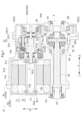
- FIG. 1 is a cross-sectional view taken along an axial direction of a vehicle drive device provided with a parking lock mechanism according to a first embodiment
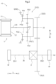
- FIG. 1 is a skeleton diagram of a vehicle drive device provided with a parking lock mechanism according to a first embodiment
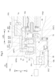
- FIG. 1 is a cross-sectional view showing a parking lock mechanism according to a first embodiment
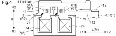
- FIG. 13 is a diagram showing an example of control of a current flowing through a coil by a current control unit.
- FIG. 13 is a diagram showing an example of control of a current flowing through a coil by a current control unit.
- FIG. 13 is a diagram showing an example of control of a current flowing through a coil by a current control unit.
- FIG. 13 is a diagram showing an example of control of a current flowing through a coil by a current control unit.
- FIG. 11 is a cross-sectional view showing a parking lock mechanism according to a second embodiment.
- the parking lock mechanism 100 is provided in a vehicle drive device 10.
- the vehicle drive device 10 includes a rotating electric machine 1, a power transmission mechanism 2, and a differential gear mechanism 3.
- the rotating electric machine 1 includes a stator 11 and a rotor 12.
- the rotating electric machine 1 functions as a driving force source for wheels W (see FIG. 2) equipped on a vehicle.
- the rotating electric machine 1 has a function as a motor (electric motor) that receives a supply of electric power to generate power, and a function as a generator (electric power generator) that receives a supply of power to generate electric power.
- the rotating electric machine 1 is electrically connected to an electric storage device (not shown) such as a battery or a capacitor.
- the rotating electric machine 1 generates driving force by running using the electric power stored in the electric storage device.
- the rotating electric machine 1 also generates power using the driving force transmitted from the wheels W to charge the electric storage device.
- the power transmission mechanism 2 transmits the rotation of the rotor 12 to the differential gear mechanism 3.
- the power transmission mechanism 2 includes a planetary gear mechanism 21, a first gear 22, and a second gear 23.
- the differential gear mechanism 3 is configured to distribute the rotation transmitted from the power transmission mechanism 2 to a pair of wheels W.
- the planetary gear mechanism 21 and the first gear 22 are arranged on a first axis X1, which is the rotational axis of the rotor 12.
- the second gear 23 and the differential gear mechanism 3 are arranged on a second axis X2 that is different from the first axis X1.
- the first axis X1 and the second axis X2 are arranged so as to be parallel to each other.
- the direction parallel to the first axis X1 and the second axis X2 is referred to as the "axial direction L".
- One side of the axial direction L is referred to as the "first axial side L1”
- the other side of the axial direction L is referred to as the "second axial side L2”.
- the direction perpendicular to each of the first axis X1 and the second axis X2 is referred to as the "radial direction R" based on each axis. Note that when it is not necessary to distinguish which axis is used as the reference, or when it is clear which axis is used as the reference, it may simply be referred to as the "radial direction R".
- the rotating electric machine 1, the power transmission mechanism 2, and the differential gear mechanism 3 are housed in a case 9.
- the case 9 includes a first case portion 91, a second case portion 92 joined to the first case portion 91 from a first axial side L1, and a third case portion 93 joined to the first case portion 91 from a second axial side L2.
- the first case portion 91 includes a first peripheral wall portion 91a, a second peripheral wall portion 91b, and a partition portion 91c.
- the first peripheral wall portion 91a is formed to cover the outside of the rotating electric machine 1 in the radial direction R.
- the second peripheral wall portion 91b is formed to cover the outside of the planetary gear mechanism 21 and the differential gear mechanism 3 in the radial direction R.
- the partition portion 91c is formed to separate the space inside the radial direction R of the first peripheral wall portion 91a from the space inside the radial direction R of the second peripheral wall portion 91b in the axial direction L.
- first peripheral wall portion 91a is disposed on the first axial side L1 of the partition portion 91c
- second peripheral wall portion 91b is disposed on the second axial side L2 of the partition portion 91c.
- the first peripheral wall portion 91a is formed in a cylindrical shape that opens to the first axial side L1
- the second peripheral wall portion 91b is formed in a cylindrical shape that opens to the second axial side L2.
- “cylindrical” means that the overall shape is generally cylindrical, even if there are some irregularly shaped parts (the same meaning applies below to other expressions that use "shape" to describe shapes, etc.).
- the second case portion 92 has a first side wall portion 92a.
- the first side wall portion 92a is formed to cover the first axial side L1 of the rotating electric machine 1.
- the second case portion 92 is joined to the first case portion 91 from the first axial side L1 so that the opening of the first peripheral wall portion 91a on the first axial side L1 is blocked by the first side wall portion 92a.
- the third case portion 93 has a second side wall portion 93a.
- the second side wall portion 93a is formed to cover the second axial side L2 of the power transmission mechanism 2 and the differential gear mechanism 3.
- the third case portion 93 is joined to the first case portion 91 from the second axial side L2 so that the opening of the second peripheral wall portion 91b on the second axial side L2 is blocked by the second side wall portion 93a.
- the stator 11 of the rotating electric machine 1 includes a cylindrical stator core 11a.
- the stator core 11a is fixed to a non-rotating member NR.
- the stator core 11a is fixed to a first peripheral wall portion 91a of the case 9, which serves as the non-rotating member NR.
- the rotor 12 of the rotating electric machine 1 includes a cylindrical rotor core 12a.
- the rotor core 12a is supported rotatably relative to the stator core 11a.
- the rotor 12 further includes a rotor shaft 12b connected to rotate integrally with the rotor core 12a.
- the rotating electric machine 1 is an inner rotor type rotating electric machine. Therefore, the rotor core 12a is arranged on the inside in the radial direction R relative to the stator core 11a. Also, the rotor shaft 12b is arranged on the inside in the radial direction R relative to the rotor core 12a.
- the rotating electric machine 1 is a rotating field type rotating electric machine. Therefore, a stator coil is wound around the stator core 11a.
- the stator coil is wound around the stator core 11a so that a pair of coil end portions 11b protruding on both sides in the axial direction L are formed relative to the stator core 11a.
- a permanent magnet is provided in the rotor core 12a.
- the rotor shaft 12b is formed in a cylindrical shape with an axis along the axial direction L.
- the rotor shaft 12b is arranged to protrude from the rotor core 12a on both sides in the axial direction L.
- the portion of the rotor shaft 12b protruding from the rotor core 12a to the first axial side L1 is rotatably supported by the first side wall portion 92a of the case 9 via the first rotor bearing B11.
- the portion of the rotor shaft 12b protruding from the rotor core 12a to the second axial side L2 is rotatably supported by the partition wall portion 91c of the case 9 via the second rotor bearing B12.
- the planetary gear mechanism 21 is configured to reduce the rotation of the rotor 12 and transmit it to the first gear 22.
- the planetary gear mechanism 21 includes a sun gear SG, a carrier CR, and a ring gear RG.
- the sun gear SG is connected to the rotor 12 so as to rotate integrally with it.
- the sun gear SG is connected to the rotor shaft 12b via the input shaft I so as to rotate integrally with it.
- the input shaft I is formed to extend along the axial direction L.
- the input shaft I is formed to extend from the sun gear SG to the first axial side L1.
- the input shaft I is arranged to penetrate the partition wall portion 91c of the case 9 in the axial direction L.
- a portion of the input shaft I located on the first axial side L1 from the partition wall portion 91c is arranged inward in the radial direction R with respect to the rotor shaft 12b, and is connected to the rotor shaft 12b by spline engagement.
- the carrier CR rotatably supports the first pinion gear PG1 and the second pinion gear PG2, which rotate integrally with each other.
- Each of the first pinion gear PG1 and the second pinion gear PG2 rotates (spins) around its own axis and also rotates (revolves) together with the carrier CR around the sun gear SG.
- Each of the first pinion gear PG1 and the second pinion gear PG2 is provided at intervals from each other along its own orbital trajectory.
- the first pinion gear PG1 meshes with the sun gear SG.
- the second pinion gear PG2 meshes with the ring gear RG.
- the second pinion gear PG2 is formed with a smaller diameter than the first pinion gear PG1.
- the second pinion gear PG2 is positioned on the first axial side L1 of the first pinion gear PG1.
- the carrier CR is connected to the first gear 22 so as to rotate integrally with it.
- the first gear 22 is disposed on the second axial side L2 relative to the planetary gear mechanism 21.
- the first gear 22 is then rotatably supported on the second side wall portion 93a of the case 9 via the first support bearing B2.
- the first support bearing B2 is disposed radially inward relative to the first gear 22.
- the ring gear RG is fixed to the non-rotating member NR.
- the ring gear RG is fixed to the second peripheral wall portion 91b of the case 9, which serves as the non-rotating member NR.
- the first gear 22 and the second gear 23 mesh with each other.
- the second gear 23 is rotatably supported on the second side wall portion 93a of the case 9 via the second support bearing B3.
- the second support bearing B3 is disposed on the inside of the second gear 23 in the radial direction R.
- the second gear 23 is formed with a larger diameter than the first gear 22. Therefore, in this embodiment, the rotation of the carrier CR of the planetary gear mechanism 21 is decelerated between the first gear 22 and the second gear 23 and transmitted to the differential gear mechanism 3.
- the differential gear mechanism 3 includes a differential case 31, a pair of pinion gears 32, and a first side gear 33 and a second side gear 34.
- the pair of pinion gears 32, and the first side gear 33 and second side gear 34 are all bevel gears.
- the differential case 31 is a hollow member that houses a pair of pinion gears 32, as well as a first side gear 33 and a second side gear 34.
- the differential case 31 is connected to the second gear 23 so as to rotate integrally with it.
- the differential case 31 is rotatably supported relative to the case 9 via the differential bearing B4.
- the end of the first axial side L1 of the differential case 31 is rotatably supported relative to the second peripheral wall portion 91b of the case 9 via the differential bearing B4.
- the pair of pinion gears 32 are arranged facing each other with a gap in the radial direction R based on the second axis X2.
- the pair of pinion gears 32 are attached to a pinion shaft 32a that is supported so as to rotate integrally with the differential case 31.
- Each of the pair of pinion gears 32 is configured to be rotatable (spinning) around the pinion shaft 32a and rotatable (revolving) around the second axis X2.
- the first side gear 33 and the second side gear 34 mesh with a pair of pinion gears 32.
- the first side gear 33 and the second side gear 34 are arranged to rotate about the second axis X2.
- the first side gear 33 is arranged on the first axial side L1 relative to the pinion shaft 32a.
- the second side gear 34 is arranged on the second axial side L2 relative to the pinion shaft 32a.
- the first side gear 33 is connected to rotate integrally with a first drive shaft DS1 (see FIG. 2) that is drivingly connected to a wheel W on a first axial side L1 via a transmission shaft 35 extending along the axial direction L.
- the transmission shaft 35 is arranged on the second axis X2.
- the transmission shaft 35 is arranged to pass outside the rotating electric machine 1 in the radial direction R and penetrate the first side wall portion 92a in the axial direction L.
- the transmission shaft 35 is inserted from the first axial side L1 to the inside of the first side gear 33 in the radial direction R, and they are connected to each other by spline engagement.
- the second side gear 34 is connected to rotate integrally with the second drive shaft DS2 (see FIG. 2), which is drivingly connected to the wheel W on the second axial side L2.
- the parking lock mechanism 100 selectively restricts the rotation of a target rotating member T that rotates in conjunction with the wheels W of a vehicle.
- the target rotating member T is a carrier CR.
- the parking lock mechanism 100 includes a locking member 4 and a drive unit 5.
- the locking member 4 is configured to be movable between a locked position P1 where it engages with the target rotating member T to restrict the rotation of the target rotating member T, and an unlocked position P2 where it moves away from the target rotating member T to allow the target rotating member T to rotate.
- the locking member 4 is supported so as not to be rotatable relative to the non-rotating member NR.
- the locking member 4 has a first cylindrical portion 41 formed in a cylindrical shape.
- the direction along the axis of the first cylindrical portion 41 is the axial direction L. Furthermore, the direction perpendicular to the axis of the first cylindrical portion 41 is the radial direction R.
- the radial first side R1 either the outside of the radial direction R or the inside of the radial direction R is referred to as the "radial first side R1," and the other is referred to as the "radial second side R2.”
- the inside of the radial direction R is the radial first side R1
- the outside of the radial direction R is the radial second side R2.
- the non-rotating member NR has a second cylindrical portion 94 formed in a cylindrical shape.
- the second cylindrical portion 94 is formed so as to protrude inward in the radial direction R from the second peripheral wall portion 91b of the case 9 as the non-rotating member NR, and to protrude from the partition wall portion 91c of the case 9 to the second axial side L2.
- the first cylindrical portion 41 is disposed on the first radial side R1 relative to the second cylindrical portion 94.
- An engaging portion 411 is formed on the first opposing surface 41a, which is the surface on the second radial side R2 of the first cylindrical portion 41.
- An engaged portion 941 is formed on the second opposing surface 94a, which is the surface on the first radial side R1 of the second cylindrical portion 94 and faces the first opposing surface 41a.
- the engaging portion 411 is engaged with the engaged portion 941 so as to be movable in the axial direction L and not to rotate relative to the engaged portion 941.
- the engaging portion 411 is an uneven portion formed along the circumferential direction of the first opposing surface 41a, and is formed continuously along the axial direction L.
- the engaged portion 941 is an uneven portion formed along the circumferential direction of the second opposing surface 94a, and is formed continuously along the axial direction L.
- a locking portion 412 is formed at the end of the axial second side L2 on the surface (here, the inner peripheral surface) of the radial first side R1 of the first cylindrical portion 41, which engages with the locked portion Ta of the target rotating member T from the axial first side L1 and restricts the rotation of the target rotating member T.
- the locking portion 412 is a concave-convex formed along the circumferential direction on the inner peripheral surface of the first cylindrical portion 41, and is continuously formed from the end face of the axial second side L2 of the first cylindrical portion 41 toward the axial first side L1.
- the locked portion Ta is a concave-convex formed along the circumferential direction on the surface (here, the outer peripheral surface) of the radial second side R2 of the carrier CR at a portion of the axial first side L1 beyond the second pinion gear PG2, and is continuously formed from the end face of the axial first side L1 of the carrier CR toward the axial second side L2.
- the parking lock mechanism 100 when the locking member 4 is in the unlocked position P2, it moves away from the target rotating member T to the first axial side L1, and the parking lock mechanism 100 is in an unlocked state.
- the locking member 4 moves from the unlocked position P2 to the second axial side L2 and is in the locked position P1
- the engaging portion 412 of the first cylindrical portion 41 engages with the engaged portion Ta of the target rotating member T
- the parking lock mechanism 100 is in a locked state.
- the locked position P1 and the unlocked position P2 are arranged along the axial direction L.
- the direction in which the locking member 4 moves between the locked position P1 and the unlocked position P2 is referred to as the "moving direction M.”
- the locked position P1 and the unlocked position P2 are disposed along the axial direction L, and therefore the moving direction M coincides with the axial direction L.
- the drive unit 5 is a device that drives the locking member 4.
- the drive unit 5 includes a position holding unit 6 and an electromagnetic drive unit 7.
- the position holding unit 6 is equipped with a permanent magnet 61 supported by the locking member 4.
- the position holding unit 6 holds the locking member 4 at each of the locked position P1 and the unlocked position P2 by the magnetic force of the permanent magnet 61.
- the permanent magnet 61 may be constructed by joining multiple split magnets.
- the permanent magnet 61 is a permanent magnet having an N pole and an S pole.
- the permanent magnet 61 is arranged so that the N pole and the S pole are aligned in the moving direction M.
- the permanent magnet 61 is arranged so that the N pole and the S pole are aligned in the moving direction M on the side of the electromagnetic drive unit 7 (in this embodiment, the first radial side R1).
- one permanent magnet 61 is arranged so that the N pole and the S pole of the permanent magnet 61 are aligned in the moving direction M on the side of the electromagnetic drive unit 7, or two permanent magnets 6 are arranged so that the N pole of one permanent magnet 61 and the S pole of the other permanent magnet 61 are aligned in the moving direction M on the side of the electromagnetic drive unit 7.
- one of the N pole and the S pole of the permanent magnet 61 is referred to as the "first pole 61A” and the other is referred to as the "second pole 61B".
- the permanent magnet 61 is arranged so that the first pole 61A and the second pole 61B are aligned in this order from the axial first side L1 to the axial second side L2.
- the first pole 61A is a north pole and the second pole 61B is a south pole.
- the electromagnetic drive unit 7 uses electromagnetic force generated by electricity from a power source (not shown) to move the locking member 4 from the unlocked position P2 to the locked position P1, and from the locked position P1 to the unlocked position P2.
- the parking lock mechanism 100 has the following features: A parking lock mechanism 100 that selectively restricts rotation of a target rotating member T that rotates in conjunction with a wheel W of a vehicle, a locking member 4 that is movable between a locked position P1 where the locking member 4 engages with a target rotating member T to restrict rotation of the target rotating member T and an unlocked position P2 where the locking member 4 is separated from the target rotating member T to allow rotation of the target rotating member T and is supported so as not to rotate relative to a non-rotating member NR; A drive device 5 that drives the lock member 4,
- the drive unit 5 is a position retaining portion 6 including a permanent magnet 61 supported by the locking member 4, the position retaining portion 6 retaining the locking member 4 at either the locked position P1 or the unlocked position P2 by the magnetic force of the permanent magnet 61;
- the locking member 4 is provided with an electromagnetic drive unit 7 that uses electromagnetic force generated by power from a power source to move the locking member 4 from the unlocked position P2 to the locked position P1, and from the
- the locking member 4 can be held at either the locked position P1 or the unlocked position P2 by the magnetic force of the permanent magnet 61. This makes it possible to maintain the parking lock mechanism 100 in the locked or unlocked state without consuming energy such as power. Furthermore, when switching the state of the parking lock mechanism 100, the locking member 4 can be moved between the locked position P1 and the unlocked position P2 by electromagnetic force generated using power from a power source. In other words, electromagnetic force is generated only when the locking member 4 is to be moved, and the state of the parking lock mechanism 100 can be appropriately switched. As described above, according to this configuration, the parking lock mechanism 100 can be switched between the locked state and the unlocked state while keeping low the energy consumption in the parking lock mechanism 100. Therefore, the energy efficiency of the parking lock mechanism 100 can be improved.
- the permanent magnet 61 is formed in a cylindrical shape having an axis along the moving direction M.
- the permanent magnet 61 is fixed to the first cylindrical portion 41 of the locking member 4.
- the permanent magnet 61 is fixed to a portion of the inner circumferential surface of the first cylindrical portion 41 closer to the first axial side L1 than the engaging portion 412.
- the electromagnetic drive unit 7 is formed in a cylindrical shape concentric with the permanent magnet 61.
- the electromagnetic drive unit 7 includes a fixed unit 70.
- the fixed unit 70 is fixed to the non-rotating member NR.
- the non-rotating member NR has a third cylindrical portion 95 formed in a cylindrical shape.
- the third cylindrical portion 95 is disposed on the first radial side R1 from the second cylindrical portion 94.
- the third cylindrical portion 95 is formed so as to protrude from the partition portion 91c of the case 9 as the non-rotating member NR to the second axial side L2.
- the fixing portion 70 is formed in a cylindrical shape concentric with the third cylindrical portion 95.
- the fixing portion 70 is fixed to the surface (here, the outer circumferential surface) of the third cylindrical portion 95 on the second radial side R2.
- the fixing portion 70 is arranged so as to overlap with the first cylindrical portion 41 when viewed in the radial direction R.
- the fixing portion 70 and the first cylindrical portion 41 overlap with each other when viewed in the radial direction.
- the fixing portion 70 is arranged on the first radial side R1 with respect to the first cylindrical portion 41, at a position overlapping with the engaged portion 941 when viewed in the radial direction R.
- "overlapping when viewed in a particular direction” means that when a virtual line parallel to the line of sight is moved in each direction perpendicular to the virtual line, there is at least a portion of an area where the virtual line intersects both of the two elements.
- the locking member 4 includes the first cylindrical portion 41 formed in a cylindrical shape
- the electromagnetic drive unit 7 includes a fixed unit 70 fixed to the non-rotating member NR.
- the lock position P1 and the unlock position P2 are disposed along the axial direction L
- the first cylindrical portion 41 and the fixing portion 70 are disposed so as to overlap each other when viewed in the radial direction R.
- This configuration makes it easier to keep the axial dimension L of the parking lock mechanism 100 small compared to a configuration in which the first cylindrical portion 41 of the locking member 4 and the fixed portion 70 of the electromagnetic drive unit 7 are arranged so that they do not overlap each other when viewed radially along the radial direction R.
- the non-rotating member NR includes a second cylindrical portion 94 formed in a cylindrical shape.
- the first cylindrical portion 41 is disposed on a first radial side R1 relative to the second cylindrical portion 94
- An engagement portion 411 is formed on a first opposing surface 41 a, which is a surface on the second radial side R2 of the first cylindrical portion 41.
- An engaged portion 941 is formed on a second opposing surface 94a, which is a surface on the radial first side R1 of the second cylindrical portion 94 and faces the first opposing surface 41a.
- the engaging portion 411 is engaged with the engaged portion 941 so as to be movable in the axial direction L but not rotatable relative thereto.
- the fixing portion 70 is disposed on the first radial side R1 relative to the first cylindrical portion 41 at a position overlapping with the engaged portion 941 as viewed in the radial direction R.
- the engaging portion 411 formed on the first opposing surface 41a of the first cylindrical portion 41 of the locking member 4 is engaged with the engaged portion 941 formed on the second opposing surface 94a of the second cylindrical portion 94 of the non-rotating member NR so as to be movable in the axial direction L but not rotatable relative thereto.
- This makes it possible to appropriately move the locking member 4 in the axial direction L relative to the non-rotating member NR while realizing a configuration in which the first cylindrical portion 41 of the locking member 4 is disposed on the radial first side R1 with respect to the second cylindrical portion 94 of the non-rotating member NR.
- the fixed portion 70 of the electromagnetic drive unit 7 is disposed on the radial first side R1 with respect to the first cylindrical portion 41 of the locking member 4, at a position that overlaps with the engaged portion 941 of the second cylindrical portion 94 of the non-rotating member NR as viewed in the radial direction along the radial direction R.
- This makes it easier to keep the dimension of the parking lock mechanism 100 in the axial direction L small, compared to a configuration in which the engaged portion 941 of the second cylindrical portion 94 of the non-rotating member NR and the fixed portion 70 of the electromagnetic drive unit 7 are disposed so as not to overlap with each other as viewed in the radial direction along the radial direction R.
- the electromagnetic drive unit 7 further includes a first magnetic body portion 71, a second magnetic body portion 72, a third magnetic body portion 73, and a coil 74.
- Each of the first magnetic body part 71, the second magnetic body part 72, and the third magnetic body part 73 is made of a magnetic material.
- the first magnetic body part 71, the second magnetic body part 72, and the third magnetic body part 73 are arranged so as to be lined up in the order described above with a gap between them in the moving direction M.
- the first magnetic body part 71, the second magnetic body part 72, and the third magnetic body part 73 are formed so as to protrude from the fixed part 70 toward the second radial side R2.
- the first magnetic body part 71, the second magnetic body part 72, and the third magnetic body part 73 are arranged so as to be lined up in the order described above from the first axial side L1 toward the second axial side L2.
- the coil 74 is configured to generate a magnetic flux passing through the first magnetic body part 71, the second magnetic body part 72, and the third magnetic body part 73 when electricity is applied.
- the coil 74 is wound on the surface of the second radial side R2 of the fixed part 70 (here, the outer peripheral surface) between the first magnetic body part 71 and the second magnetic body part 72 in the moving direction M, and between the second magnetic body part 72 and the third magnetic body part 73 in the moving direction M.
- the drive device 5 further includes an energization control unit 8 that controls the current flowing through the coil 74.
- an energization control unit 8 that controls the current flowing through the coil 74.
- the first pole 61A attracts the first magnetic body portion 71
- the second pole 61B attracts the second magnetic body portion 72.
- the first pole 61A is disposed between the first magnetic body portion 71 and the second magnetic body portion 72 in the moving direction M
- the second pole 61B is disposed so as to overlap with the second magnetic body portion 72 when viewed in the radial direction along the radial direction R.
- the current supply control unit 8 passes current through the coil 74 so that the first magnetic body part 71 becomes a pole (here, a north pole) that repels the first pole 61A, the second magnetic body part 72 becomes a pole (here, a south pole) that repels the second pole 61B, and the third magnetic body part 73 becomes a pole (here, a north pole) that attracts the second pole 61B.
- the locking member 4 supporting the permanent magnet 61 moves in the moving direction M so as to approach the target rotating member T.
- the locking member 4 moves to the locked position P1.
- the current supply control unit 8 stops the current supply to the coil 74.
- the first pole 61A attracts the second magnetic material portion 72
- the second pole 61B attracts the third magnetic material portion 73.
- the first pole 61A is arranged so as to overlap with the second magnetic material portion 72 when viewed in the radial direction R
- the second pole 61B is arranged so as to overlap with the third magnetic material portion 73 when viewed in the radial direction R.
- the current control unit 8 passes current through the coil 74 so that the second magnetic body part 72 becomes a pole (here, a north pole) that repels the first pole 61A, the third magnetic body part 73 becomes a pole (here, a south pole) that repels the second pole 61B, and the first magnetic body part 71 becomes a pole (here, a south pole) that attracts the first pole 61A.
- the locking member 4 supporting the permanent magnet 61 moves in the moving direction M so as to move away from the target rotating member T.
- the current control unit 8 stops the current flow to the coil 74 (see FIG. 4).
- the direction in which the locking member 4 moves between the locked position P1 and the unlocked position P2 is defined as a moving direction M
- the permanent magnet 61 is arranged so that the N pole and the S pole are aligned in the moving direction M.
- the electromagnetic drive unit 7 includes a first magnetic body unit 71, a second magnetic body unit 72, and a third magnetic body unit 73, each of which is made of a magnetic material, and a coil 74 that generates a magnetic flux passing through the first magnetic body unit 71, the second magnetic body unit 72, and the third magnetic body unit 73,
- the first magnetic body portion 71, the second magnetic body portion 72, and the third magnetic body portion 73 are arranged in the movement direction M with a gap between them in the order described above.
- the magnetic force of the permanent magnet 61 appropriately holds the locking member 4 in each of the locked and unlocked positions P1 and P2, and the electromagnetic force generated using power from the power source appropriately moves the locking member 4 in the movement direction M between the locked and unlocked positions P1 and P2.
- the drive device 5 includes an electric current control unit 8 that controls the electric current flowing through the coil 74.
- One of the north pole and the south pole of the permanent magnet 61 is designated as a first pole 61A, and the other is designated as a second pole 61B.
- the first pole 61A attracts the first magnetic body portion 71 and the second pole 61B attracts the second magnetic body portion 72.
- the first pole 61A attracts the second magnetic material portion 72
- the second pole 61B attracts the third magnetic material portion 73.
- This configuration allows the drive unit 5, which holds the locking member 4 in each of the locked position P1 and the unlocked position P2 by the magnetic force of the permanent magnet 61, to be realized with a simple configuration. This makes it easier to reduce the cost and size of the parking lock mechanism 100.
- the current supply control unit 8 When the locking member 4 is moved from the unlocked position P2 to the locked position P1, a current is passed through the coil 74 so that the first magnetic body portion 71 becomes a pole that repels the first pole 61A, the second magnetic body portion 72 becomes a pole that repels the second pole 61B, and the third magnetic body portion 73 becomes a pole that attracts the second pole 61B.
- This configuration allows the drive device 5, which moves the locking member 4 between the locked position P1 and the unlocked position P2 using electromagnetic force generated by power from a power source, to be realized with a simple configuration. This makes it easier to reduce the cost and size of the parking lock mechanism 100.
- Second embodiment A parking lock mechanism 100 according to a second embodiment will be described below with reference to FIG. 8.
- the manner in which the parking lock mechanism 100 is installed relative to the vehicle drive device 10 is different from that of the first embodiment.
- the configuration of the periphery of the parking lock mechanism 100 in the vehicle drive device 10 is different from that of the first embodiment.
- the following description will focus on the differences from the first embodiment. Note that points that are not particularly described are the same as those in the first embodiment.
- the third cylindrical portion 95 of the case 9 is formed to protrude from the first side wall portion 92a toward the first axial side L1.
- the parking lock mechanism 100 is disposed on the inside of the third cylindrical portion 95 in the radial direction R.
- the second case portion 92 further includes a third side wall portion 96 formed to cover the first axial side L1 of the parking lock mechanism 100.
- the third side wall portion 96 is formed to extend from the end of the first axial side L1 of the third cylindrical portion 95 toward the inside in the radial direction R.
- the second cylindrical portion 94 of the case 9 is formed to protrude from the third side wall portion 96 to the second axial side L2.
- the outside in the radial direction R is the first radial side R1
- the inside in the radial direction R is the second radial side R2. Therefore, in this embodiment, the third cylindrical portion 95 is disposed further outward in the radial direction R than the second cylindrical portion 94.
- the fixed portion 70 is fixed to the inner peripheral surface of the third cylindrical portion 95.
- the first magnetic material portion 71, the second magnetic material portion 72, and the third magnetic material portion 73 are formed to protrude inward in the radial direction R from the fixed portion 70.
- the first cylindrical portion 41 of the locking member 4 is disposed radially outward of the second cylindrical portion 94 in the radial direction R.
- a permanent magnet 61 is fixed to the outer peripheral surface of the first cylindrical portion 41.
- the target rotating member T is the rotor shaft 12b. Therefore, in this embodiment, a locked portion Ta is formed on the end of the first axial side L1 on the inner peripheral surface of the rotor shaft 12b. Also, the second cylindrical portion 94 is disposed on the inside in the radial direction R of the rotor shaft 12b. And a locking portion 412 is formed on the end of the second axial side L2 on the outer peripheral surface of the first cylindrical portion 41, which is disposed on the outside in the radial direction R of the second cylindrical portion 94.
- the target rotating member T is the carrier CR or the rotor shaft 12b.
- the present invention is not limited to such a configuration.
- the target rotating member T may be a parking gear connected to a rotating member that constitutes a power transmission path connecting the rotating electric machine 1 and the wheels W.
- the electromagnetic drive unit 7 further includes another magnetic body in addition to the first magnetic body 71, the second magnetic body 72, and the third magnetic body 73.
- the movement direction M is the axial direction L
- the present invention is not limited to such a configuration, and the movement direction M may be a direction other than the axial direction L (for example, the radial direction R).
- the permanent magnet 61 is formed in a cylindrical shape having an axis along the movement direction M.
- the present invention is not limited to such a configuration, and may be configured, for example, such that multiple permanent magnets 61 are distributed around an axis along the movement direction M.
- the parking lock mechanism (100) comprises: A parking lock mechanism (100) that selectively restricts rotation of a target rotating member (T) that rotates in conjunction with a wheel (W) of a vehicle, comprising: a locking member (4) that is movable between a locked position (P1) where the locking member engages with the target rotating member (T) to restrict rotation of the target rotating member (T) and an unlocked position (P2) where the locking member is separated from the target rotating member (T) to allow rotation of the target rotating member (T), and that is supported so as not to rotate relative to a non-rotating member (NR); a drive device (5) for driving the lock member (4); The drive device (5) a position retaining unit (6) including a permanent magnet (61) supported by the locking member (4) and retaining the locking member (4) at each of the locked position (P1) and the unlocked position (P2) by a magnetic force of the permanent magnet (61); and an electromagnetic drive unit (7) that uses electromagnetic force generated by power from a power source to move the locking member (4) from
- the locking member (4) can be held in either the locked position (P1) or the unlocked position (P2) by the magnetic force of the permanent magnet (61), thereby making it possible to maintain the parking lock mechanism (100) in a locked or unlocked state without consuming energy such as power. Furthermore, when switching the state of the parking lock mechanism (100), the locking member (4) can be moved between the locked position (P1) and the unlocked position (P2) by electromagnetic force generated using power from a power source. In other words, electromagnetic force is generated only when the locking member (4) is moved, and the state of the parking lock mechanism (100) can be appropriately switched. As described above, according to the present configuration, the parking lock mechanism (100) can be switched between a locked state and an unlocked state while keeping energy consumption in the parking lock mechanism (100) low, thereby improving the energy efficiency of the parking lock mechanism (100).
- the locking member (4) includes a first cylindrical portion (41) formed in a cylindrical shape
- the electromagnetic drive unit (7) includes a fixed unit (70) fixed to the non-rotating member (NR)
- a direction along the axis of the first cylindrical portion (41) is defined as an axial direction (L)
- a direction perpendicular to the axis is defined as a radial direction (R)
- the locking position (P1) and the unlocking position (P2) are disposed along the axial direction (L)
- the first cylindrical portion (41) and the fixing portion (70) are arranged so as to overlap each other when viewed in the radial direction (R).
- This configuration makes it easier to keep the axial (L) dimension of the parking lock mechanism (100) small compared to a configuration in which the first cylindrical portion (41) of the locking member (4) and the fixed portion (70) of the electromagnetic drive unit (7) are arranged so as not to overlap each other when viewed in the radial direction (R).
- the non-rotating member (NR) includes a second cylindrical portion (94) formed in a cylindrical shape, One of the outer side and the inner side in the radial direction (R) is defined as a radial first side (R1), and the other is defined as a radial second side (R2).
- the first cylindrical portion (41) is disposed on the radial first side (R1) with respect to the second cylindrical portion (94),
- An engagement portion (411) is formed on a first opposing surface (41a) which is a surface on the second radial side (R2) of the first cylindrical portion (41), an engaged portion (941) is formed on a second opposing surface (94a) on the radial first side (R1) of the second cylindrical portion (94) and opposed to the first opposing surface (41a);
- the engaging portion (411) is engaged with the engaged portion (941) so as to be movable in the axial direction (L) and non-rotatable relative thereto, It is preferable that the fixing portion (70) is arranged on the first radial side (R1) relative to the first cylindrical portion (41) at a position overlapping with the engaged portion (941) when viewed radially along the radial direction (R).
- the engaging portion (411) formed on the first opposing surface (41a) of the first cylindrical portion (41) of the locking member (4) is engaged with the engaged portion (941) formed on the second opposing surface (94a) of the second cylindrical portion (94) of the non-rotating member (NR) so as to be movable in the axial direction (L) but not rotatable relative thereto.
- This allows the locking member (4) to be appropriately moved relative to the non-rotating member (NR) in the axial direction (L) while realizing a configuration in which the first cylindrical portion (41) of the locking member (4) is disposed on the first radial side (R1) with respect to the second cylindrical portion (94) of the non-rotating member (NR).
- the fixed portion (70) of the electromagnetic drive unit (7) is disposed on the first radial side (R1) with respect to the first cylindrical portion (41) of the locking member (4) and at a position overlapping with the engaged portion (941) of the second cylindrical portion (94) of the non-rotating member (NR) as viewed in the radial direction along the radial direction (R).
- the direction in which the locking member (4) moves between the locking position (P1) and the unlocking position (P2) is defined as a moving direction (M)
- the permanent magnet (61) is arranged so that its N pole and S pole are aligned in the moving direction (M)
- the electromagnetic driving unit (7) includes a first magnetic body portion (71), a second magnetic body portion (72), and a third magnetic body portion (73), each of which is made of a magnetic material, and a coil (74) that generates a magnetic flux passing through the first magnetic body portion (71), the second magnetic body portion (72), and the third magnetic body portion (73), It is preferable that the first magnetic body portion (71), the second magnetic body portion (72), and the third magnetic body portion (73) are arranged in the order described above with a gap between them in the movement direction (M).
- the magnetic force of the permanent magnet (61) properly holds the locking member (4) in each of the locked position (P1) and the unlocked position (P2), and the electromagnetic force generated using power from the power source properly moves the locking member (4) in the movement direction (M) between the locked position (P1) and the unlocked position (P2).
- the drive device (5) further includes an electric current control unit (8) that controls an electric current flowing through the coil (74),
- One of the N pole and the S pole of the permanent magnet (61) is designated as a first pole (61A), and the other is designated as a second pole (61B).
- the first pole (61A) attracts the first magnetic portion (71), and the second pole (61B) attracts the second magnetic portion (72),
- the first pole (61A) attracts the second magnetic portion (72) and the second pole (61B) attracts the third magnetic portion (73).
- the drive device (5) that holds the locking member (4) in each of the locked position (P1) and the unlocked position (P2) by the magnetic force of the permanent magnet (61) can be realized with a simple configuration. This makes it easier to reduce the cost and size of the parking lock mechanism (100).
- the current control unit (8) When the locking member (4) is moved from the unlocked position (P2) to the locked position (P1), a current is passed through the coil (74) so that the first magnetic body portion (71) becomes a pole that repels the first pole (61A), the second magnetic body portion (72) becomes a pole that repels the second pole (61B), and the third magnetic body portion (73) becomes a pole that attracts the second pole (61B);
- a current is passed through the coil (74) so that the second magnetic body portion (72) becomes a pole that repels the first pole (61A), the third magnetic body portion (73) becomes a pole that repels the second pole (61B), and the first magnetic body portion (71) becomes a pole that attracts the first pole (61A).
- the drive device (5) that moves the locking member (4) between the locked position (P1) and the unlocked position (P2) using electromagnetic force generated by power from a power source can be realized with a simple configuration. This makes it easier to reduce the cost and size of the parking lock mechanism (100).
- the permanent magnet (61) is formed in a cylindrical shape having an axis along the moving direction (M), It is preferable that the electromagnetic driving portion (7) is formed in a cylindrical shape concentric with the permanent magnet (61).
- the technology disclosed herein can be used in a parking lock mechanism that selectively restricts the rotation of a target rotating member that rotates in conjunction with the wheels of a vehicle.
Landscapes
- Engineering & Computer Science (AREA)
- General Engineering & Computer Science (AREA)
- Mechanical Engineering (AREA)
- Physics & Mathematics (AREA)
- Electromagnetism (AREA)
- Gear-Shifting Mechanisms (AREA)
Abstract
車両における車輪と連動して回転する対象回転部材(T)の回転を選択的に規制するパーキングロック機構(100)は、対象回転部材(T)に係合して対象回転部材(T)の回転を規制するロック位置(P1)と、対象回転部材(T)から離間して対象回転部材(T)の回転を許容する非ロック位置(P2)とに移動可能であり、非回転部材(NR)に対して相対回転不能に支持されたロック部材(4)と、ロック部材(4)を駆動する駆動装置(5)と、を備え、駆動装置(5)は、ロック部材(4)に支持された永久磁石(61)の磁力により、ロック部材(4)をロック位置(P1)と非ロック位置(P2)とのそれぞれに保持する位置保持部(6)と、電源からの電力により発生させた電磁力により、ロック部材(4)の非ロック位置(P2)からロック位置(P1)への移動、及びロック部材(4)のロック位置(P1)から非ロック位置(P2)への移動を行う電磁駆動部(7)と、を備える。
Description
本発明は、車両における車輪と連動して回転する対象回転部材の回転を選択的に規制するパーキングロック機構に関する。
このようなパーキングロック機構の一例が、下記の特許文献1に開示されている。以下、背景技術の説明では、特許文献1における符号を括弧内に引用する。
特許文献1のパーキングロック機構は、第1リングギヤ(45)を非回転部材(32)に対して選択的に固定する第1ブレーキ(33)と、第2リングギヤ(46)を非回転部材(32)に対して選択的に固定する第2ブレーキ(34)と、を備えている。そして、第1ブレーキ(33)が第1リングギヤ(45)を非回転部材(32)に対して固定すると共に、第2ブレーキ(34)が第2リングギヤ(46)を非回転部材(32)に対して固定することで、車輪と連動して回転する出力軸(48)の回転を規制する。
特許文献1のパーキングロック機構では、第1ブレーキ(33)及び第2ブレーキ(34)のそれぞれは、油圧ポンプ(24)から油圧が供給されない状態では係合状態となり、油圧ポンプ(24)から所定値以上の油圧が供給された状態では解放状態となるノーマルクローズ型の係合装置である。そのため、車両の走行中、第1ブレーキ(33)及び第2ブレーキ(34)のいずれか一方に油圧を供給し続ける必要がある。その結果、パーキングロック機構のエネルギ効率が悪化していた。
そこで、エネルギ効率を高めることが可能なパーキングロック機構の実現が望まれる。
上記に鑑みた、パーキングロック機構の特徴構成は、
車両における車輪と連動して回転する対象回転部材の回転を選択的に規制するパーキングロック機構であって、
前記対象回転部材に係合して前記対象回転部材の回転を規制するロック位置と、前記対象回転部材から離間して前記対象回転部材の回転を許容する非ロック位置と、に移動可能であり、非回転部材に対して相対回転不能に支持されたロック部材と、
前記ロック部材を駆動する駆動装置と、を備え、
前記駆動装置は、
前記ロック部材に支持された永久磁石を備え、前記永久磁石の磁力により、前記ロック部材を前記ロック位置と前記非ロック位置とのそれぞれの位置に保持する位置保持部と、
電源からの電力により発生させた電磁力により、前記ロック部材の前記非ロック位置から前記ロック位置への移動、及び、前記ロック部材の前記ロック位置から前記非ロック位置への移動を行う電磁駆動部と、を備える点にある。
車両における車輪と連動して回転する対象回転部材の回転を選択的に規制するパーキングロック機構であって、
前記対象回転部材に係合して前記対象回転部材の回転を規制するロック位置と、前記対象回転部材から離間して前記対象回転部材の回転を許容する非ロック位置と、に移動可能であり、非回転部材に対して相対回転不能に支持されたロック部材と、
前記ロック部材を駆動する駆動装置と、を備え、
前記駆動装置は、
前記ロック部材に支持された永久磁石を備え、前記永久磁石の磁力により、前記ロック部材を前記ロック位置と前記非ロック位置とのそれぞれの位置に保持する位置保持部と、
電源からの電力により発生させた電磁力により、前記ロック部材の前記非ロック位置から前記ロック位置への移動、及び、前記ロック部材の前記ロック位置から前記非ロック位置への移動を行う電磁駆動部と、を備える点にある。
この特徴構成によれば、永久磁石の磁力により、ロック部材をロック位置と非ロック位置とのそれぞれの位置に保持することができる。これにより、電力等のエネルギを消費することなく、パーキングロック機構をロック状態又は非ロック状態に維持することができる。
また、パーキングロック機構の状態を切り替える場合には、電源からの電力を用いて発生させた電磁力により、ロック部材をロック位置と非ロック位置との間で移動させることができる。つまり、ロック部材を移動させる際にのみ電磁力を発生させ、パーキングロック機構の状態を適切に切り替えることができる。
以上のように、本特徴構成によれば、パーキングロック機構におけるエネルギ消費を少なく抑えつつ、パーキングロック機構をロック状態と非ロック状態とに切り替えることができる。したがって、パーキングロック機構のエネルギ効率を高めることができる。
また、パーキングロック機構の状態を切り替える場合には、電源からの電力を用いて発生させた電磁力により、ロック部材をロック位置と非ロック位置との間で移動させることができる。つまり、ロック部材を移動させる際にのみ電磁力を発生させ、パーキングロック機構の状態を適切に切り替えることができる。
以上のように、本特徴構成によれば、パーキングロック機構におけるエネルギ消費を少なく抑えつつ、パーキングロック機構をロック状態と非ロック状態とに切り替えることができる。したがって、パーキングロック機構のエネルギ効率を高めることができる。
1.第1の実施形態
以下では、第1の実施形態に係るパーキングロック機構100について、図面を参照して説明する。本実施形態では、パーキングロック機構100は、車両用駆動装置10に設けられている。
以下では、第1の実施形態に係るパーキングロック機構100について、図面を参照して説明する。本実施形態では、パーキングロック機構100は、車両用駆動装置10に設けられている。
まず、車両用駆動装置10について説明する。図1及び図2に示すように、車両用駆動装置10は、回転電機1と、動力伝達機構2と、差動歯車機構3と、を備えている。
回転電機1は、ステータ11及びロータ12を備えている。回転電機1は、車両が備える車輪W(図2参照)の駆動力源として機能する。回転電機1は、電力の供給を受けて動力を発生するモータ(電動機)としての機能と、動力の供給を受けて電力を発生するジェネレータ(発電機)としての機能とを有している。具体的には、回転電機1は、バッテリやキャパシタ等の蓄電装置(図示を省略)と電気的に接続されている。そして、回転電機1は、蓄電装置に蓄えられた電力により力行して駆動力を発生する。また、回転電機1は、車輪Wの側から伝達される駆動力により発電を行って蓄電装置を充電する。
動力伝達機構2は、ロータ12の回転を差動歯車機構3に伝達する。動力伝達機構2は、遊星歯車機構21と、第1ギヤ22と、第2ギヤ23と、を備えている。差動歯車機構3は、動力伝達機構2から伝達された回転を一対の車輪Wに分配するように構成されている。
本実施形態では、遊星歯車機構21及び第1ギヤ22は、ロータ12の回転軸心である第1軸X1上に配置されている。第2ギヤ23及び差動歯車機構3は、第1軸X1とは異なる第2軸X2上に配置されている。第1軸X1と第2軸X2とは、互いに平行となるように配置されている。
以下の説明では、第1軸X1及び第2軸X2に平行な方向を「軸方向L」とする。そして、軸方向Lの一方側を「軸方向第1側L1」とし、軸方向Lの他方側を「軸方向第2側L2」とする。また、第1軸X1及び第2軸X2のそれぞれに直交する方向を、各軸を基準とした「径方向R」とする。なお、どの軸を基準とするかを区別する必要がない場合や、どの軸を基準とするかが明らかである場合には、単に「径方向R」と記す場合がある。
図1に示すように、回転電機1、動力伝達機構2、及び差動歯車機構3は、ケース9に収容されている。
本実施形態では、ケース9は、第1ケース部91と、当該第1ケース部91に対して軸方向第1側L1から接合された第2ケース部92と、第1ケース部91に対して軸方向第2側L2から接合された第3ケース部93と、を備えている。
第1ケース部91は、第1周壁部91aと、第2周壁部91bと、隔壁部91cと、を備えている。第1周壁部91aは、回転電機1の径方向Rの外側を覆うように形成されている。第2周壁部91bは、遊星歯車機構21及び差動歯車機構3の径方向Rの外側を覆うように形成されている。隔壁部91cは、第1周壁部91aに対して径方向Rの内側の空間と、第2周壁部91bに対して径方向Rの内側の空間とを、軸方向Lに隔てるように形成されている。本実施形態では、隔壁部91cに対して軸方向第1側L1に第1周壁部91aが配置され、隔壁部91cに対して軸方向第2側L2に第2周壁部91bが配置されている。そして、第1周壁部91aは軸方向第1側L1に開口する筒状に形成され、第2周壁部91bは軸方向第2側L2に開口する筒状に形成されている。ここで、「筒状」とは、多少の異形部分を有していたとしてもその全体としての概略形状が筒であることを意味する(以下、形状等に関して「状」を付して用いる他の表現に関しても同趣旨である)。
第2ケース部92は、第1側壁部92aを備えている。第1側壁部92aは、回転電機1の軸方向第1側L1を覆うように形成されている。本実施形態では、第1周壁部91aの軸方向第1側L1の開口が第1側壁部92aにより塞がれるように、第2ケース部92が第1ケース部91に対して軸方向第1側L1から接合されている。
第3ケース部93は、第2側壁部93aを備えている。第2側壁部93aは、動力伝達機構2及び差動歯車機構3の軸方向第2側L2を覆うように形成されている。本実施形態では、第2周壁部91bの軸方向第2側L2の開口が第2側壁部93aにより塞がれるように、第3ケース部93が第1ケース部91に対して軸方向第2側L2から接合されている。
図1に示すように、回転電機1のステータ11は、円筒状のステータコア11aを備えている。ステータコア11aは、非回転部材NRに固定されている。本実施形態では、ステータコア11aは、非回転部材NRとしてのケース9の第1周壁部91aに固定されている。回転電機1のロータ12は、円筒状のロータコア12aを備えている。ロータコア12aは、ステータコア11aに対して回転可能に支持されている。本実施形態では、ロータ12は、ロータコア12aと一体的に回転するように連結されたロータ軸12bを更に備えている。
本実施形態では、回転電機1はインナロータ型の回転電機である。そのため、ロータコア12aが、ステータコア11aに対して径方向Rの内側に配置されている。また、ロータ軸12bが、ロータコア12aに対して径方向Rの内側に配置されている。
また、本実施形態では、回転電機1は回転界磁型の回転電機である。そのため、ステータコア11aには、ステータコイルが巻装されている。本実施形態では、ステータコイルは、ステータコア11aに対して軸方向Lの両側に突出した一対のコイルエンド部11bが形成されるように、ステータコア11aに巻装されている。また、図示は省略するが、ロータコア12aには、永久磁石が設けられている。
本実施形態では、ロータ軸12bは、軸方向Lに沿う軸心を有する筒状に形成されている。また、本実施形態では、ロータ軸12bは、ロータコア12aから軸方向Lの両側に突出するように配置されている。そして、ロータ軸12bにおけるロータコア12aから軸方向第1側L1に突出した部分は、第1ロータ軸受B11を介して、ケース9の第1側壁部92aに対して回転自在に支持されている。また、ロータ軸12bにおけるロータコア12aから軸方向第2側L2に突出した部分は、第2ロータ軸受B12を介して、ケース9の隔壁部91cに対して回転自在に支持されている。
遊星歯車機構21は、ロータ12の回転を減速して、第1ギヤ22に伝達するように構成されている。遊星歯車機構21は、サンギヤSGと、キャリヤCRと、リングギヤRGと、を備えている。
サンギヤSGは、ロータ12と一体的に回転するように連結されている。本実施形態では、サンギヤSGは、入力軸Iを介して、ロータ軸12bと一体的に回転するように連結されている。
入力軸Iは、軸方向Lに沿って延在するように形成されている。本実施形態では、入力軸Iは、サンギヤSGから軸方向第1側L1に延出するように形成されている。また、本実施形態では、入力軸Iは、ケース9の隔壁部91cを軸方向Lに貫通するように配置されている。そして、入力軸Iにおける隔壁部91cよりも軸方向第1側L1に位置する部分が、ロータ軸12bに対して径方向Rの内側に配置され、ロータ軸12bとスプライン係合により連結されている。
キャリヤCRは、互いに一体的に回転する第1ピニオンギヤPG1と第2ピニオンギヤPG2とを回転自在に支持している。第1ピニオンギヤPG1及び第2ピニオンギヤPG2のそれぞれは、自己の軸心回りに回転(自転)すると共に、キャリヤCRと共にサンギヤSGを中心として回転(公転)する。第1ピニオンギヤPG1及び第2ピニオンギヤPG2のそれぞれは、自己の公転軌跡に沿って、互いに間隔を空けて複数設けられている。
第1ピニオンギヤPG1は、サンギヤSGに噛み合っている。第2ピニオンギヤPG2は、リングギヤRGに噛み合っている。第2ピニオンギヤPG2は、第1ピニオンギヤPG1よりも小径に形成されている。本実施形態では、第2ピニオンギヤPG2は、第1ピニオンギヤPG1よりも軸方向第1側L1に配置されている。
キャリヤCRは、第1ギヤ22と一体的に回転するように連結されている。本実施形態では、第1ギヤ22は、遊星歯車機構21に対して軸方向第2側L2に配置されている。そして、第1ギヤ22は、第1支持軸受B2を介して、ケース9の第2側壁部93aに対して回転自在に支持されている。本実施形態では、第1支持軸受B2は、第1ギヤ22に対して径方向Rの内側に配置されている。
リングギヤRGは、非回転部材NRに対して固定されている。本実施形態では、リングギヤRGは、非回転部材NRとしてのケース9の第2周壁部91bに固定されている。
第1ギヤ22と第2ギヤ23とは、互いに噛み合っている。本実施形態では、第2ギヤ23は、第2支持軸受B3を介して、ケース9の第2側壁部93aに対して回転自在に支持されている。第2支持軸受B3は、第2ギヤ23に対して径方向Rの内側に配置されている。また、本実施形態では、第2ギヤ23は、第1ギヤ22よりも大径に形成されている。そのため、本実施形態では、遊星歯車機構21のキャリヤCRの回転が、第1ギヤ22と第2ギヤ23との間で減速されて差動歯車機構3に伝達される。
本実施形態では、差動歯車機構3は、差動ケース31と、一対のピニオンギヤ32と、第1サイドギヤ33及び第2サイドギヤ34と、を備えている。ここでは、一対のピニオンギヤ32、並びに第1サイドギヤ33及び第2サイドギヤ34は、いずれも傘歯車である。
差動ケース31は、一対のピニオンギヤ32、並びに第1サイドギヤ33及び第2サイドギヤ34を収容する中空の部材である。差動ケース31は、第2ギヤ23と一体的に回転するように連結されている。
本実施形態では、差動ケース31は、差動軸受B4を介して、ケース9に対して回転自在に支持されている。図1に示す例では、差動ケース31の軸方向第1側L1の端部が、差動軸受B4を介して、ケース9の第2周壁部91bに対して回転自在に支持されている。
一対のピニオンギヤ32は、第2軸X2を基準とした径方向Rに間隔を空けて、互いに対向するように配置されている。そして、一対のピニオンギヤ32は、差動ケース31と一体的に回転するように支持されたピニオンシャフト32aに取り付けられている。一対のピニオンギヤ32のそれぞれは、ピニオンシャフト32aを中心として回転(自転)可能、かつ、第2軸X2を中心として回転(公転)可能に構成されている。
第1サイドギヤ33及び第2サイドギヤ34は、一対のピニオンギヤ32に噛み合っている。第1サイドギヤ33及び第2サイドギヤ34は、第2軸X2を回転軸心として回転するように配置されている。第1サイドギヤ33は、ピニオンシャフト32aに対して軸方向第1側L1に配置されている。そして、第2サイドギヤ34は、ピニオンシャフト32aに対して軸方向第2側L2に配置されている。
本実施形態では、第1サイドギヤ33は、軸方向Lに沿って延在する伝達軸35を介して、軸方向第1側L1の車輪Wに駆動連結された第1ドライブシャフトDS1(図2参照)と一体的に回転するように連結されている。伝達軸35は、第2軸X2上に配置されている。本実施形態では、伝達軸35は、回転電機1に対して径方向Rの外側を通り、第1側壁部92aを軸方向Lに貫通するように配置されている。図1に示す例では、第1サイドギヤ33に対して径方向Rの内側に、軸方向第1側L1から伝達軸35が挿入され、それらがスプライン係合によって互いに連結されている。
本実施形態では、第2サイドギヤ34は、軸方向第2側L2の車輪Wに駆動連結された第2ドライブシャフトDS2(図2参照)と一体的に回転するように連結されている。
次に、パーキングロック機構100について説明する。パーキングロック機構100は、車両における車輪Wと連動して回転する対象回転部材Tの回転を選択的に規制する。本実施形態では、対象回転部材Tは、キャリヤCRである。
図3に示すように、パーキングロック機構100は、ロック部材4と、駆動装置5と、を備えている。
ロック部材4は、対象回転部材Tに係合して対象回転部材Tの回転を規制するロック位置P1と、対象回転部材Tから離間して対象回転部材Tの回転を許容する非ロック位置P2と、に移動可能に構成されている。ロック部材4は、非回転部材NRに対して相対回転不能に支持されている。本実施形態では、ロック部材4は、筒状に形成された第1筒状部41を備えている。
なお、本実施形態では、第1筒状部41の軸心に沿う方向が軸方向Lである。また、第1筒状部41の軸心に直交する方向が径方向Rである。以下の説明では、径方向Rの外側及び径方向Rの内側のいずれか一方を「径方向第1側R1」とし、他方を「径方向第2側R2」とする。本実施形態では、径方向Rの内側が径方向第1側R1であり、径方向Rの外側が径方向第2側R2である。
本実施形態では、非回転部材NRは、筒状に形成された第2筒状部94を備えている。本実施形態では、第2筒状部94は、非回転部材NRとしてのケース9の第2周壁部91bから径方向Rの内側に突出すると共に、ケース9の隔壁部91cから軸方向第2側L2に突出するように形成されている。
本実施形態では、第1筒状部41は、第2筒状部94に対して径方向第1側R1に配置されている。そして、第1筒状部41における径方向第2側R2の面である第1対向面41aには、係合部411が形成されている。また、第2筒状部94における径方向第1側R1の面であって第1対向面41aに対向する第2対向面94aには、被係合部941が形成されている。係合部411は、被係合部941に対して、軸方向Lに移動可能であって相対回転不能に係合されている。ここでは、係合部411は、第1対向面41aに周方向に沿って形成された凹凸であり、軸方向Lに沿って連続的に形成されている。そして、被係合部941は、第2対向面94aに周方向に沿って形成された凹凸であり、軸方向Lに沿って連続的に形成されている。
また、本実施形態では、第1筒状部41の径方向第1側R1の面(ここでは、内周面)における軸方向第2側L2の端部に、対象回転部材Tの被係止部Taに対して、軸方向第1側L1から係合し、対象回転部材Tの回転を規制する係止部412が形成されている。ここでは、係止部412は、第1筒状部41の内周面に周方向に沿って形成された凹凸であり、第1筒状部41の軸方向第2側L2の端面から軸方向第1側L1に向けて連続的に形成されている。そして、被係止部Taは、キャリヤCRにおける第2ピニオンギヤPG2よりも軸方向第1側L1の部分の径方向第2側R2の面(ここでは、外周面)に周方向に沿って形成された凹凸であり、キャリヤCRの軸方向第1側L1の端面から軸方向第2側L2に向けて連続的に形成されている。
本実施形態では、ロック部材4が非ロック位置P2にある場合、ロック部材4は対象回転部材Tに対して軸方向第1側L1に離間し、パーキングロック機構100が非ロック状態となる。一方、ロック部材4が非ロック位置P2から軸方向第2側L2に移動してロック位置P1にある場合、第1筒状部41の係止部412が対象回転部材Tの被係止部Ta係合し、パーキングロック機構100がロック状態となる。このように、本実施形態では、ロック位置P1と非ロック位置P2とは、軸方向Lに沿って配置されている。
以下の説明では、ロック部材4がロック位置P1と非ロック位置P2との間で移動する方向を「移動方向M」とする。上記の通り、本実施形態では、ロック位置P1と非ロック位置P2とは軸方向Lに沿って配置されているため、移動方向Mは軸方向Lに一致する。
駆動装置5は、ロック部材4を駆動する装置である。駆動装置5は、位置保持部6と、電磁駆動部7と、を備えている。
位置保持部6は、ロック部材4に支持された永久磁石61を備えている。位置保持部6は、永久磁石61の磁力により、ロック部材4をロック位置P1と非ロック位置P2とのそれぞれの位置に保持する。永久磁石61は、複数の分割磁石を接合して構成されていても良い。
永久磁石61は、N極及びS極を有する永久磁石である。本実施形態では、永久磁石61は、N極とS極とが移動方向Mに並ぶように配置されている。具体的には、永久磁石61は、電磁駆動部7の側(本実施形態では、径方向第1側R1)においてN極とS極とが移動方向Mに並ぶように配置される。例えば、1つの永久磁石61が、当該永久磁石61のN極とS極とが電磁駆動部7の側において移動方向Mに並ぶように配置され、或いは、2つの永久磁石6が、一方の永久磁石61のN極と他方の永久磁石61のS極とが電磁駆動部7の側において移動方向Mに並ぶように配置される。以下の説明では、永久磁石61のN極及びS極の一方を「第1極61A」とし、他方を「第2極61B」とする。永久磁石61は、軸方向第1側L1から軸方向第2側L2に向けて、第1極61A、第2極61Bの順に並ぶように配置されている。本実施形態では、第1極61AはN極であり、第2極61BはS極である。
電磁駆動部7は、電源(図示を省略)からの電力により発生させた電磁力により、ロック部材4の非ロック位置P2からロック位置P1への移動、及び、ロック部材4のロック位置P1から非ロック位置P2への移動を行う。
以上のように、パーキングロック機構100は、
車両における車輪Wと連動して回転する対象回転部材Tの回転を選択的に規制するパーキングロック機構100であって、
対象回転部材Tに係合して対象回転部材Tの回転を規制するロック位置P1と、対象回転部材Tから離間して対象回転部材Tの回転を許容する非ロック位置P2と、に移動可能であり、非回転部材NRに対して相対回転不能に支持されたロック部材4と、
ロック部材4を駆動する駆動装置5と、を備え、
駆動装置5は、
ロック部材4に支持された永久磁石61を備え、永久磁石61の磁力により、ロック部材4をロック位置P1と非ロック位置P2とのそれぞれの位置に保持する位置保持部6と、
電源からの電力により発生させた電磁力により、ロック部材4の非ロック位置P2からロック位置P1への移動、及び、ロック部材4のロック位置P1から非ロック位置P2への移動を行う電磁駆動部7と、を備える。
車両における車輪Wと連動して回転する対象回転部材Tの回転を選択的に規制するパーキングロック機構100であって、
対象回転部材Tに係合して対象回転部材Tの回転を規制するロック位置P1と、対象回転部材Tから離間して対象回転部材Tの回転を許容する非ロック位置P2と、に移動可能であり、非回転部材NRに対して相対回転不能に支持されたロック部材4と、
ロック部材4を駆動する駆動装置5と、を備え、
駆動装置5は、
ロック部材4に支持された永久磁石61を備え、永久磁石61の磁力により、ロック部材4をロック位置P1と非ロック位置P2とのそれぞれの位置に保持する位置保持部6と、
電源からの電力により発生させた電磁力により、ロック部材4の非ロック位置P2からロック位置P1への移動、及び、ロック部材4のロック位置P1から非ロック位置P2への移動を行う電磁駆動部7と、を備える。
この構成によれば、永久磁石61の磁力により、ロック部材4をロック位置P1と非ロック位置P2とのそれぞれの位置に保持することができる。これにより、電力等のエネルギを消費することなく、パーキングロック機構100をロック状態又は非ロック状態に維持することができる。
また、パーキングロック機構100の状態を切り替える場合には、電源からの電力を用いて発生させた電磁力により、ロック部材4をロック位置P1と非ロック位置P2との間で移動させることができる。つまり、ロック部材4を移動させる際にのみ電磁力を発生させ、パーキングロック機構100の状態を適切に切り替えることができる。
以上のように、本構成によれば、パーキングロック機構100におけるエネルギ消費を少なく抑えつつ、パーキングロック機構100をロック状態と非ロック状態とに切り替えることができる。したがって、パーキングロック機構100のエネルギ効率を高めることができる。
また、パーキングロック機構100の状態を切り替える場合には、電源からの電力を用いて発生させた電磁力により、ロック部材4をロック位置P1と非ロック位置P2との間で移動させることができる。つまり、ロック部材4を移動させる際にのみ電磁力を発生させ、パーキングロック機構100の状態を適切に切り替えることができる。
以上のように、本構成によれば、パーキングロック機構100におけるエネルギ消費を少なく抑えつつ、パーキングロック機構100をロック状態と非ロック状態とに切り替えることができる。したがって、パーキングロック機構100のエネルギ効率を高めることができる。
本実施形態では、永久磁石61は、移動方向Mに沿う軸心を有する円筒状に形成されている。そして、永久磁石61は、ロック部材4の第1筒状部41に固定されている。図示の例では、永久磁石61は、第1筒状部41の内周面における係止部412よりも軸方向第1側L1の部分に固定されている。また、本実施形態では、電磁駆動部7は、永久磁石61と同心の円筒状に形成されている。
この構成によれば、駆動装置5の大部分を円筒状に形成することができるため、回転を規制する対象である対象回転部材Tと同心に駆動装置5を配置し易い。したがって、車両用駆動装置10へのパーキングロック機構100の搭載性を高めることができる。
本実施形態では、電磁駆動部7は、固定部70を備えている。固定部70は、非回転部材NRに固定されている。
本実施形態では、非回転部材NRは、筒状に形成された第3筒状部95を備えている。第3筒状部95は、第2筒状部94よりも径方向第1側R1に配置されている。本実施形態では、第3筒状部95は、非回転部材NRとしてのケース9の隔壁部91cから軸方向第2側L2に突出するように形成されている。
本実施形態では、固定部70は、第3筒状部95と同心の筒状に形成されている。そして、固定部70は、第3筒状部95における径方向第2側R2の面(ここでは、外周面)に固定されている。また、本実施形態では、固定部70は、径方向Rに沿う径方向視で、第1筒状部41と重複するように配置されている。図3に示す例では、ロック部材4がロック位置P1にある場合、及び、ロック部材4が非ロック位置P2にある場合の双方において、固定部70と第1筒状部41とが径方向視で互いに重複している。また、本実施形態では、固定部70は、第1筒状部41に対して径方向第1側R1であって、径方向Rに沿う径方向視で被係合部941と重複する位置に配置されている。ここで、2つの要素の配置に関して、「特定方向視で重複する」とは、その視線方向に平行な仮想直線を当該仮想直線と直交する各方向に移動させた場合に、当該仮想直線が2つの要素の双方に交わる領域が少なくとも一部に存在することを指す。
このように、本実施形態では、ロック部材4は、筒状に形成された第1筒状部41を備え、
電磁駆動部7は、非回転部材NRに固定された固定部70を備え、
ロック位置P1と非ロック位置P2とは、軸方向Lに沿って配置され、
第1筒状部41と固定部70とは、径方向Rに沿う径方向視で、互いに重複するように配置されている。
電磁駆動部7は、非回転部材NRに固定された固定部70を備え、
ロック位置P1と非ロック位置P2とは、軸方向Lに沿って配置され、
第1筒状部41と固定部70とは、径方向Rに沿う径方向視で、互いに重複するように配置されている。
この構成によれば、ロック部材4の第1筒状部41と、電磁駆動部7の固定部70とが、径方向Rに沿う径方向視で互いに重複しないように配置された構成に比べて、パーキングロック機構100の軸方向Lの寸法を小さく抑え易い。
また、本実施形態では、非回転部材NRは、筒状に形成された第2筒状部94を備え、
第1筒状部41は、第2筒状部94に対して径方向第1側R1に配置され、
第1筒状部41における径方向第2側R2の面である第1対向面41aに係合部411が形成され、
第2筒状部94における径方向第1側R1の面であって第1対向面41aに対向する第2対向面94aに被係合部941が形成され、
係合部411は、被係合部941に対して、軸方向Lに移動可能であって相対回転不能に係合され、
第1筒状部41に対して径方向第1側R1であって、径方向Rに沿う径方向視で被係合部941と重複する位置に、固定部70が配置されている。
第1筒状部41は、第2筒状部94に対して径方向第1側R1に配置され、
第1筒状部41における径方向第2側R2の面である第1対向面41aに係合部411が形成され、
第2筒状部94における径方向第1側R1の面であって第1対向面41aに対向する第2対向面94aに被係合部941が形成され、
係合部411は、被係合部941に対して、軸方向Lに移動可能であって相対回転不能に係合され、
第1筒状部41に対して径方向第1側R1であって、径方向Rに沿う径方向視で被係合部941と重複する位置に、固定部70が配置されている。
この構成によれば、ロック部材4の第1筒状部41の第1対向面41aに形成された係合部411が、非回転部材NRの第2筒状部94の第2対向面94aに形成された被係合部941に対して、軸方向Lに移動可能であって相対回転不能に係合されている。これにより、ロック部材4の第1筒状部41が非回転部材NRの第2筒状部94に対して径方向第1側R1に配置された構成を実現しつつ、ロック部材4を非回転部材NRに対して適切に軸方向Lに相対移動させることができる。
また、本構成によれば、ロック部材4の第1筒状部41に対して径方向第1側R1であって、径方向Rに沿う径方向視で非回転部材NRにおける第2筒状部94の被係合部941と重複する位置に、電磁駆動部7の固定部70が配置されている。これにより、非回転部材NRにおける第2筒状部94の被係合部941と、電磁駆動部7の固定部70とが、径方向Rに沿う径方向視で互いに重複しないように配置された構成に比べて、パーキングロック機構100の軸方向Lの寸法を小さく抑え易い。
また、本構成によれば、ロック部材4の第1筒状部41に対して径方向第1側R1であって、径方向Rに沿う径方向視で非回転部材NRにおける第2筒状部94の被係合部941と重複する位置に、電磁駆動部7の固定部70が配置されている。これにより、非回転部材NRにおける第2筒状部94の被係合部941と、電磁駆動部7の固定部70とが、径方向Rに沿う径方向視で互いに重複しないように配置された構成に比べて、パーキングロック機構100の軸方向Lの寸法を小さく抑え易い。
図3に示すように、電磁駆動部7は、第1磁性体部71と、第2磁性体部72と、第3磁性体部73と、コイル74と、を更に備えている。
第1磁性体部71、第2磁性体部72、及び第3磁性体部73のそれぞれは、磁性体で構成されている。第1磁性体部71、第2磁性体部72、及び第3磁性体部73は、移動方向Mに互いに間隔を空けて記載の順に並ぶように配置されている。本実施形態では、第1磁性体部71、第2磁性体部72、及び第3磁性体部73は、固定部70から径方向第2側R2に向けて突出するように形成されている。そして、第1磁性体部71、第2磁性体部72、及び第3磁性体部73は、軸方向第1側L1から軸方向第2側L2に向けて、記載の順に並ぶように配置されている。
コイル74は、通電により、第1磁性体部71、第2磁性体部72、及び第3磁性体部73を通る磁束を発生させるように構成されている。本実施形態では、コイル74は、固定部70の径方向第2側R2の面(ここでは、外周面)における、第1磁性体部71と第2磁性体部72との移動方向Mの間、及び、第2磁性体部72と第3磁性体部73との移動方向Mの間のそれぞれに巻回されている。
本実施形態では、駆動装置5は、コイル74に流す電流を制御する通電制御部8を更に備えている。以下では、図4から図7を参照して、ロック部材4を非ロック位置P2からロック位置P1へ移動させる場合、及び、ロック部材4をロック位置P1から非ロック位置P2へ移動させる場合における、通電制御部8によるコイル74に流す電流の制御の一例について説明する。なお、本例では、永久磁石61の第1極61AがN極であり、永久磁石61の第2極61BがS極である。
図4に示すように、通電制御部8がコイル74に電流を流さず、ロック部材4が非ロック位置P2にある場合、第1極61Aが第1磁性体部71を吸引し、第2極61Bが第2磁性体部72を吸引した状態となる。なお、本実施形態では、ロック部材4が非ロック位置P2にある場合、第1極61Aが、第1磁性体部71と第2磁性体部72との移動方向Mの間に配置され、第2極61Bが、径方向Rに沿う径方向視で第2磁性体部72と重複するように配置されている。
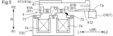
図5に示すように、通電制御部8は、ロック部材4を非ロック位置P2からロック位置P1へ移動させる場合、第1磁性体部71が第1極61Aと反発する極(ここでは、N極)となり、第2磁性体部72が第2極61Bと反発する極(ここでは、S極)となり、第3磁性体部73が第2極61Bと引き合う極(ここでは、N極)となるように、コイル74に電流を流す。その結果、永久磁石61を支持するロック部材4が、対象回転部材Tに近付くように移動方向Mに移動する。そして、ロック部材4の係止部412が対象回転部材Tの被係止部Taに係合しつつ、ロック部材4がロック位置P1まで移動する。ロック部材4がロック位置P1まで移動した後、通電制御部8はコイル74への通電を停止する。
図6に示すように、通電制御部8がコイル74に電流を流さず、ロック部材4がロック位置P1にある場合、第1極61Aが第2磁性体部72を吸引し、第2極61Bが第3磁性体部73を吸引した状態となる。なお、本実施形態では、ロック部材4が非ロック位置P2にある場合、第1極61Aが、径方向Rに沿う径方向視で第2磁性体部72と重複するように配置され、第2極61Bが、径方向Rに沿う径方向視で第3磁性体部73と重複するように配置されている。
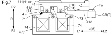
図7に示すように、通電制御部8は、ロック部材4をロック位置P1から非ロック位置P2へ移動させる場合、第2磁性体部72が第1極61Aと反発する極(ここでは、N極)となり、第3磁性体部73が第2極61Bと反発する極(ここでは、S極)となり、第1磁性体部71が第1極61Aと引き合う極(ここでは、S極)となるように、コイル74に電流を流す。その結果、永久磁石61を支持するロック部材4が、対象回転部材Tから離れるように移動方向Mに移動する。そして、係止部412の被係止部Taに対する係合が解除され、ロック部材4が非ロック位置P2まで移動する。ロック部材4が非ロック位置P2まで移動した後、通電制御部8はコイル74への通電を停止する(図4参照)。
このように、本実施形態では、ロック部材4がロック位置P1と非ロック位置P2との間で移動する方向を移動方向Mとして、
永久磁石61は、N極とS極とが移動方向Mに並ぶように配置され、
電磁駆動部7は、それぞれが磁性体で構成された第1磁性体部71、第2磁性体部72、及び第3磁性体部73と、第1磁性体部71、第2磁性体部72、及び第3磁性体部73を通る磁束を発生させるコイル74と、を備え、
第1磁性体部71、第2磁性体部72、及び第3磁性体部73は、移動方向Mに互いに間隔を空けて記載の順に並ぶように配置されている。
永久磁石61は、N極とS極とが移動方向Mに並ぶように配置され、
電磁駆動部7は、それぞれが磁性体で構成された第1磁性体部71、第2磁性体部72、及び第3磁性体部73と、第1磁性体部71、第2磁性体部72、及び第3磁性体部73を通る磁束を発生させるコイル74と、を備え、
第1磁性体部71、第2磁性体部72、及び第3磁性体部73は、移動方向Mに互いに間隔を空けて記載の順に並ぶように配置されている。
この構成によれば、永久磁石61の磁力によりロック部材4をロック位置P1と非ロック位置P2とのそれぞれの位置に適切に保持すると共に、電源からの電力を用いて発生させた電磁力によりロック部材4をロック位置P1と非ロック位置P2との間で移動方向Mに適切に移動させることができる。
更に、本実施形態では、駆動装置5は、コイル74に流す電流を制御する通電制御部8を備え、
永久磁石61のN極及びS極の一方を第1極61Aとし、他方を第2極61Bとして、
コイル74に電流が流れておらず、ロック部材4が非ロック位置P2にある場合に、第1極61Aが第1磁性体部71を吸引し、第2極61Bが第2磁性体部72を吸引した状態となり、
コイル74に電流が流れておらず、ロック部材4がロック位置P1にある場合に、第1極61Aが第2磁性体部72を吸引し、第2極61Bが第3磁性体部73を吸引した状態となる。
永久磁石61のN極及びS極の一方を第1極61Aとし、他方を第2極61Bとして、
コイル74に電流が流れておらず、ロック部材4が非ロック位置P2にある場合に、第1極61Aが第1磁性体部71を吸引し、第2極61Bが第2磁性体部72を吸引した状態となり、
コイル74に電流が流れておらず、ロック部材4がロック位置P1にある場合に、第1極61Aが第2磁性体部72を吸引し、第2極61Bが第3磁性体部73を吸引した状態となる。
この構成によれば、永久磁石61の磁力によりロック部材4をロック位置P1と非ロック位置P2とのそれぞれの位置に保持する駆動装置5を、簡素な構成により実現することができる。これにより、パーキングロック機構100のコスト低減及び小型化を図り易い。
更に、本実施形態では、通電制御部8は、
ロック部材4を非ロック位置P2からロック位置P1へ移動させる場合に、第1磁性体部71が第1極61Aと反発する極となり、第2磁性体部72が第2極61Bと反発する極となり、第3磁性体部73が第2極61Bと引き合う極となるように、コイル74に電流を流し、
ロック部材4をロック位置P1から非ロック位置P2へ移動させる場合に、第2磁性体部72が第1極61Aと反発する極となり、第3磁性体部73が第2極61Bと反発する極となり、第1磁性体部71が第1極61Aと引き合う極となるように、コイル74に電流を流す。
ロック部材4を非ロック位置P2からロック位置P1へ移動させる場合に、第1磁性体部71が第1極61Aと反発する極となり、第2磁性体部72が第2極61Bと反発する極となり、第3磁性体部73が第2極61Bと引き合う極となるように、コイル74に電流を流し、
ロック部材4をロック位置P1から非ロック位置P2へ移動させる場合に、第2磁性体部72が第1極61Aと反発する極となり、第3磁性体部73が第2極61Bと反発する極となり、第1磁性体部71が第1極61Aと引き合う極となるように、コイル74に電流を流す。
この構成によれば、電源からの電力により発生させた電磁力によりロック部材4をロック位置P1と非ロック位置P2との間で移動させる駆動装置5を、簡素な構成により実現することができる。これにより、パーキングロック機構100のコスト低減及び小型化を図り易い。
2.第2の実施形態
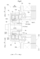
以下では、第2の実施形態に係るパーキングロック機構100について、図8を参照して説明する。本実施形態では、車両用駆動装置10に対するパーキングロック機構100の設置態様が、上記第1の実施形態のものとは異なっている。これに伴い、本実施形態では、車両用駆動装置10におけるパーキングロック機構100周辺の構成が、上記第1の実施形態のものとは異なっている。以下では、上記第1の実施形態との相違点を中心として説明する。なお、特に説明しない点については、上記第1の実施形態と同様とする。
以下では、第2の実施形態に係るパーキングロック機構100について、図8を参照して説明する。本実施形態では、車両用駆動装置10に対するパーキングロック機構100の設置態様が、上記第1の実施形態のものとは異なっている。これに伴い、本実施形態では、車両用駆動装置10におけるパーキングロック機構100周辺の構成が、上記第1の実施形態のものとは異なっている。以下では、上記第1の実施形態との相違点を中心として説明する。なお、特に説明しない点については、上記第1の実施形態と同様とする。
本実施形態では、ケース9の第3筒状部95が、第1側壁部92aから軸方向第1側L1に突出するように形成されている。そして、第3筒状部95に対して径方向Rの内側に、パーキングロック機構100が配置されている。
また、本実施形態では、第2ケース部92は、パーキングロック機構100の軸方向第1側L1を覆うように形成された第3側壁部96を更に備えている。第3側壁部96は、第3筒状部95の軸方向第1側L1の端部から径方向Rの内側に向けて延在するように形成されている。本実施形態では、ケース9の第2筒状部94が、第3側壁部96から軸方向第2側L2に突出するように形成されている。
本実施形態では、径方向Rの外側が径方向第1側R1であり、径方向Rの内側が径方向第2側R2である。そのため、本実施形態では、第3筒状部95は、第2筒状部94よりも径方向Rの外側に配置されている。そして、第3筒状部95内周面に、固定部70が固定されている。本実施形態では、第1磁性体部71、第2磁性体部72、及び第3磁性体部73は、固定部70から径方向Rの内側に向けて突出するように形成されている。
また、本実施形態では、第2筒状部94に対して径方向Rの外側に、ロック部材4の第1筒状部41が配置されている。そして、第1筒状部41の外周面に、永久磁石61が固定されている。
本実施形態では、対象回転部材Tは、ロータ軸12bである。そのため、本実施形態では、ロータ軸12bの内周面における軸方向第1側L1の端部に、被係止部Taが形成されている。また、ロータ軸12bよりも径方向Rの内側に、第2筒状部94が配置されている。そして、第2筒状部94に対して径方向Rの外側に配置された第1筒状部41の外周面における軸方向第2側L2の端部に、係止部412が形成されている。
3.その他の実施形態
(1)上記の実施形態では、対象回転部材TがキャリヤCR又はロータ軸12bである構成を例として説明した。しかし、そのような構成に限定されることなく、例えば、回転電機1と車輪Wとを結ぶ動力伝達経路を構成する回転部材そのものではなく、当該回転部材に連結されたパーキングギヤが対象回転部材Tであっても良い。
(1)上記の実施形態では、対象回転部材TがキャリヤCR又はロータ軸12bである構成を例として説明した。しかし、そのような構成に限定されることなく、例えば、回転電機1と車輪Wとを結ぶ動力伝達経路を構成する回転部材そのものではなく、当該回転部材に連結されたパーキングギヤが対象回転部材Tであっても良い。
(2)上記の実施形態では、位置保持部6がロック部材4をロック位置P1と非ロック位置P2とのそれぞれの位置に保持する構成を例として説明した。しかし、そのような構成に限定されることなく、位置保持部6がロック部材4をロック位置P1及び非ロック位置P2とは異なる位置に保持する構成としても良い。この場合、電磁駆動部7が第1磁性体部71、第2磁性体部72、及び第3磁性体部73に加えて別の磁性体部を更に備えていると好適である。
(3)上記の実施形態では、移動方向Mが軸方向Lである構成を例として説明した。しかし、そのような構成に限定されることなく、移動方向Mが軸方向L以外の方向(例えば、径方向R)であっても良い。
(4)上記の実施形態では、ロック部材4の第1筒状部41と電磁駆動部7の固定部70とが径方向Rに沿う径方向視で互いに重複するように配置された構成を例として説明した。しかし、そのような構成に限定されることなく、第1筒状部41と固定部70とが互いに軸方向Lに離れて配置されていても良い。
(5)上記の実施形態では、永久磁石61が移動方向Mに沿う軸心を有する円筒状に形成された構成を例として説明した。しかし、そのような構成に限定されることなく、例えば、複数の永久磁石61が移動方向Mに沿う軸心周りに分散配置された構成としても良い。
(6)なお、上述した各実施形態で開示された構成は、矛盾が生じない限り、他の実施形態で開示された構成と組み合わせて適用することも可能である。その他の構成に関しても、本明細書において開示された実施形態は全ての点で単なる例示に過ぎない。したがって、本開示の趣旨を逸脱しない範囲内で、適宜、種々の改変を行うことが可能である。
〔本実施形態のまとめ〕
以下では、上記において説明したパーキングロック機構(100)の概要について説明する。
以下では、上記において説明したパーキングロック機構(100)の概要について説明する。
パーキングロック機構(100)は、
車両における車輪(W)と連動して回転する対象回転部材(T)の回転を選択的に規制するパーキングロック機構(100)であって、
前記対象回転部材(T)に係合して前記対象回転部材(T)の回転を規制するロック位置(P1)と、前記対象回転部材(T)から離間して前記対象回転部材(T)の回転を許容する非ロック位置(P2)と、に移動可能であり、非回転部材(NR)に対して相対回転不能に支持されたロック部材(4)と、
前記ロック部材(4)を駆動する駆動装置(5)と、を備え、
前記駆動装置(5)は、
前記ロック部材(4)に支持された永久磁石(61)を備え、前記永久磁石(61)の磁力により、前記ロック部材(4)を前記ロック位置(P1)と前記非ロック位置(P2)とのそれぞれの位置に保持する位置保持部(6)と、
電源からの電力により発生させた電磁力により、前記ロック部材(4)の前記非ロック位置(P2)から前記ロック位置(P1)への移動、及び、前記ロック部材(4)の前記ロック位置(P1)から前記非ロック位置(P2)への移動を行う電磁駆動部(7)と、を備える。
車両における車輪(W)と連動して回転する対象回転部材(T)の回転を選択的に規制するパーキングロック機構(100)であって、
前記対象回転部材(T)に係合して前記対象回転部材(T)の回転を規制するロック位置(P1)と、前記対象回転部材(T)から離間して前記対象回転部材(T)の回転を許容する非ロック位置(P2)と、に移動可能であり、非回転部材(NR)に対して相対回転不能に支持されたロック部材(4)と、
前記ロック部材(4)を駆動する駆動装置(5)と、を備え、
前記駆動装置(5)は、
前記ロック部材(4)に支持された永久磁石(61)を備え、前記永久磁石(61)の磁力により、前記ロック部材(4)を前記ロック位置(P1)と前記非ロック位置(P2)とのそれぞれの位置に保持する位置保持部(6)と、
電源からの電力により発生させた電磁力により、前記ロック部材(4)の前記非ロック位置(P2)から前記ロック位置(P1)への移動、及び、前記ロック部材(4)の前記ロック位置(P1)から前記非ロック位置(P2)への移動を行う電磁駆動部(7)と、を備える。
この構成によれば、永久磁石(61)の磁力により、ロック部材(4)をロック位置(P1)と非ロック位置(P2)とのそれぞれの位置に保持することができる。これにより、電力等のエネルギを消費することなく、パーキングロック機構(100)をロック状態又は非ロック状態に維持することができる。
また、パーキングロック機構(100)の状態を切り替える場合には、電源からの電力を用いて発生させた電磁力により、ロック部材(4)をロック位置(P1)と非ロック位置(P2)との間で移動させることができる。つまり、ロック部材(4)を移動させる際にのみ電磁力を発生させ、パーキングロック機構(100)の状態を適切に切り替えることができる。
以上のように、本構成によれば、パーキングロック機構(100)におけるエネルギ消費を少なく抑えつつ、パーキングロック機構(100)をロック状態と非ロック状態とに切り替えることができる。したがって、パーキングロック機構(100)のエネルギ効率を高めることができる。
また、パーキングロック機構(100)の状態を切り替える場合には、電源からの電力を用いて発生させた電磁力により、ロック部材(4)をロック位置(P1)と非ロック位置(P2)との間で移動させることができる。つまり、ロック部材(4)を移動させる際にのみ電磁力を発生させ、パーキングロック機構(100)の状態を適切に切り替えることができる。
以上のように、本構成によれば、パーキングロック機構(100)におけるエネルギ消費を少なく抑えつつ、パーキングロック機構(100)をロック状態と非ロック状態とに切り替えることができる。したがって、パーキングロック機構(100)のエネルギ効率を高めることができる。
ここで、前記ロック部材(4)は、筒状に形成された第1筒状部(41)を備え、
前記電磁駆動部(7)は、前記非回転部材(NR)に固定された固定部(70)を備え、
前記第1筒状部(41)の軸心に沿う方向を軸方向(L)とし、前記軸心に直交する方向を径方向(R)として、
前記ロック位置(P1)と前記非ロック位置(P2)とは、前記軸方向(L)に沿って配置され、
前記第1筒状部(41)と前記固定部(70)とは、前記径方向(R)に沿う径方向視で、互いに重複するように配置されていると好適である。
前記電磁駆動部(7)は、前記非回転部材(NR)に固定された固定部(70)を備え、
前記第1筒状部(41)の軸心に沿う方向を軸方向(L)とし、前記軸心に直交する方向を径方向(R)として、
前記ロック位置(P1)と前記非ロック位置(P2)とは、前記軸方向(L)に沿って配置され、
前記第1筒状部(41)と前記固定部(70)とは、前記径方向(R)に沿う径方向視で、互いに重複するように配置されていると好適である。
この構成によれば、ロック部材(4)の第1筒状部(41)と、電磁駆動部(7)の固定部(70)とが、径方向(R)に沿う径方向視で互いに重複しないように配置された構成に比べて、パーキングロック機構(100)の軸方向(L)の寸法を小さく抑え易い。
前記ロック部材(4)が前記第1筒状部(41)を備えると共に、前記電磁駆動部(7)が前記固定部(70)を備えた構成において、
前記非回転部材(NR)は、筒状に形成された第2筒状部(94)を備え、
前記径方向(R)の外側及び前記径方向(R)の内側のいずれか一方を径方向第1側(R1)とし、他方を径方向第2側(R2)として、
前記第1筒状部(41)は、前記第2筒状部(94)に対して前記径方向第1側(R1)に配置され、
前記第1筒状部(41)における前記径方向第2側(R2)の面である第1対向面(41a)に係合部(411)が形成され、
前記第2筒状部(94)における前記径方向第1側(R1)の面であって前記第1対向面(41a)に対向する第2対向面(94a)に被係合部(941)が形成され、
前記係合部(411)は、前記被係合部(941)に対して、前記軸方向(L)に移動可能であって相対回転不能に係合され、
前記第1筒状部(41)に対して前記径方向第1側(R1)であって、前記径方向(R)に沿う径方向視で前記被係合部(941)と重複する位置に、前記固定部(70)が配置されていると好適である。
前記非回転部材(NR)は、筒状に形成された第2筒状部(94)を備え、
前記径方向(R)の外側及び前記径方向(R)の内側のいずれか一方を径方向第1側(R1)とし、他方を径方向第2側(R2)として、
前記第1筒状部(41)は、前記第2筒状部(94)に対して前記径方向第1側(R1)に配置され、
前記第1筒状部(41)における前記径方向第2側(R2)の面である第1対向面(41a)に係合部(411)が形成され、
前記第2筒状部(94)における前記径方向第1側(R1)の面であって前記第1対向面(41a)に対向する第2対向面(94a)に被係合部(941)が形成され、
前記係合部(411)は、前記被係合部(941)に対して、前記軸方向(L)に移動可能であって相対回転不能に係合され、
前記第1筒状部(41)に対して前記径方向第1側(R1)であって、前記径方向(R)に沿う径方向視で前記被係合部(941)と重複する位置に、前記固定部(70)が配置されていると好適である。
この構成によれば、ロック部材(4)の第1筒状部(41)の第1対向面(41a)に形成された係合部(411)が、非回転部材(NR)の第2筒状部(94)の第2対向面(94a)に形成された被係合部(941)に対して、軸方向(L)に移動可能であって相対回転不能に係合されている。これにより、ロック部材(4)の第1筒状部(41)が非回転部材(NR)の第2筒状部(94)に対して径方向第1側(R1)に配置された構成を実現しつつ、ロック部材(4)を非回転部材(NR)に対して適切に軸方向(L)に相対移動させることができる。
また、本構成によれば、ロック部材(4)の第1筒状部(41)に対して径方向第1側(R1)であって、径方向(R)に沿う径方向視で非回転部材(NR)における第2筒状部(94)の被係合部(941)と重複する位置に、電磁駆動部(7)の固定部(70)が配置されている。これにより、非回転部材(NR)における第2筒状部(94)の被係合部(941)と、電磁駆動部(7)の固定部(70)とが、径方向(R)に沿う径方向視で互いに重複しないように配置された構成に比べて、パーキングロック機構(100)の軸方向(L)の寸法を小さく抑え易い。
また、本構成によれば、ロック部材(4)の第1筒状部(41)に対して径方向第1側(R1)であって、径方向(R)に沿う径方向視で非回転部材(NR)における第2筒状部(94)の被係合部(941)と重複する位置に、電磁駆動部(7)の固定部(70)が配置されている。これにより、非回転部材(NR)における第2筒状部(94)の被係合部(941)と、電磁駆動部(7)の固定部(70)とが、径方向(R)に沿う径方向視で互いに重複しないように配置された構成に比べて、パーキングロック機構(100)の軸方向(L)の寸法を小さく抑え易い。
また、前記ロック部材(4)が前記ロック位置(P1)と前記非ロック位置(P2)との間で移動する方向を移動方向(M)として、
前記永久磁石(61)は、N極とS極とが前記移動方向(M)に並ぶように配置され、
前記電磁駆動部(7)は、それぞれが磁性体で構成された第1磁性体部(71)、第2磁性体部(72)、及び第3磁性体部(73)と、前記第1磁性体部(71)、前記第2磁性体部(72)、及び前記第3磁性体部(73)を通る磁束を発生させるコイル(74)と、を備え、
前記第1磁性体部(71)、前記第2磁性体部(72)、及び前記第3磁性体部(73)は、前記移動方向(M)に互いに間隔を空けて記載の順に並ぶように配置されていると好適である。
前記永久磁石(61)は、N極とS極とが前記移動方向(M)に並ぶように配置され、
前記電磁駆動部(7)は、それぞれが磁性体で構成された第1磁性体部(71)、第2磁性体部(72)、及び第3磁性体部(73)と、前記第1磁性体部(71)、前記第2磁性体部(72)、及び前記第3磁性体部(73)を通る磁束を発生させるコイル(74)と、を備え、
前記第1磁性体部(71)、前記第2磁性体部(72)、及び前記第3磁性体部(73)は、前記移動方向(M)に互いに間隔を空けて記載の順に並ぶように配置されていると好適である。
この構成によれば、永久磁石(61)の磁力によりロック部材(4)をロック位置(P1)と非ロック位置(P2)とのそれぞれの位置に適切に保持すると共に、電源からの電力を用いて発生させた電磁力によりロック部材(4)をロック位置(P1)と非ロック位置(P2)との間で移動方向(M)に適切に移動させることができる。
上記の構成において、前記駆動装置(5)は、前記コイル(74)に流す電流を制御する通電制御部(8)を更に備え、
前記永久磁石(61)のN極及びS極の一方を第1極(61A)とし、他方を第2極(61B)として、
前記コイル(74)に電流が流れておらず、前記ロック部材(4)が前記非ロック位置(P2)にある場合に、前記第1極(61A)が前記第1磁性体部(71)を吸引し、前記第2極(61B)が前記第2磁性体部(72)を吸引した状態となり、
前記コイル(74)に電流が流れておらず、前記ロック部材(4)が前記ロック位置(P1)にある場合に、前記第1極(61A)が前記第2磁性体部(72)を吸引し、前記第2極(61B)が前記第3磁性体部(73)を吸引した状態となると好適である。
前記永久磁石(61)のN極及びS極の一方を第1極(61A)とし、他方を第2極(61B)として、
前記コイル(74)に電流が流れておらず、前記ロック部材(4)が前記非ロック位置(P2)にある場合に、前記第1極(61A)が前記第1磁性体部(71)を吸引し、前記第2極(61B)が前記第2磁性体部(72)を吸引した状態となり、
前記コイル(74)に電流が流れておらず、前記ロック部材(4)が前記ロック位置(P1)にある場合に、前記第1極(61A)が前記第2磁性体部(72)を吸引し、前記第2極(61B)が前記第3磁性体部(73)を吸引した状態となると好適である。
この構成によれば、永久磁石(61)の磁力によりロック部材(4)をロック位置(P1)と非ロック位置(P2)とのそれぞれの位置に保持する駆動装置(5)を、簡素な構成により実現することができる。これにより、パーキングロック機構(100)のコスト低減及び小型化を図り易い。
更に上記の構成において、前記通電制御部(8)は、
前記ロック部材(4)を前記非ロック位置(P2)から前記ロック位置(P1)へ移動させる場合に、前記第1磁性体部(71)が前記第1極(61A)と反発する極となり、前記第2磁性体部(72)が前記第2極(61B)と反発する極となり、前記第3磁性体部(73)が前記第2極(61B)と引き合う極となるように、前記コイル(74)に電流を流し、
前記ロック部材(4)を前記ロック位置(P1)から前記非ロック位置(P2)へ移動させる場合に、前記第2磁性体部(72)が前記第1極(61A)と反発する極となり、前記第3磁性体部(73)が前記第2極(61B)と反発する極となり、前記第1磁性体部(71)が前記第1極(61A)と引き合う極となるように、前記コイル(74)に電流を流すと好適である。
前記ロック部材(4)を前記非ロック位置(P2)から前記ロック位置(P1)へ移動させる場合に、前記第1磁性体部(71)が前記第1極(61A)と反発する極となり、前記第2磁性体部(72)が前記第2極(61B)と反発する極となり、前記第3磁性体部(73)が前記第2極(61B)と引き合う極となるように、前記コイル(74)に電流を流し、
前記ロック部材(4)を前記ロック位置(P1)から前記非ロック位置(P2)へ移動させる場合に、前記第2磁性体部(72)が前記第1極(61A)と反発する極となり、前記第3磁性体部(73)が前記第2極(61B)と反発する極となり、前記第1磁性体部(71)が前記第1極(61A)と引き合う極となるように、前記コイル(74)に電流を流すと好適である。
この構成によれば、電源からの電力により発生させた電磁力によりロック部材(4)をロック位置(P1)と非ロック位置(P2)との間で移動させる駆動装置(5)を、簡素な構成により実現することができる。これにより、パーキングロック機構(100)のコスト低減及び小型化を図り易い。
また、上記の構成において、前記永久磁石(61)は、前記移動方向(M)に沿う軸心を有する円筒状に形成され、
前記電磁駆動部(7)は、前記永久磁石(61)と同心の円筒状に形成されていると好適である。
前記電磁駆動部(7)は、前記永久磁石(61)と同心の円筒状に形成されていると好適である。
この構成によれば、駆動装置(5)の大部分を円筒状に形成することができるため、回転を規制する対象である対象回転部材(T)と同心に駆動装置(5)を配置し易い。したがって、車両用駆動装置(10)へのパーキングロック機構(100)の搭載性を高めることができる。
本開示に係る技術は、車両における車輪と連動して回転する対象回転部材の回転を選択的に規制するパーキングロック機構に利用することができる。
100:パーキングロック機構、4:ロック部材、5:駆動装置、6:位置保持部、61:永久磁石、7:電磁駆動部、T:対象回転部材、W:車輪、P1:ロック位置、P2:非ロック位置
Claims (7)
- 車両における車輪と連動して回転する対象回転部材の回転を選択的に規制するパーキングロック機構であって、
前記対象回転部材に係合して前記対象回転部材の回転を規制するロック位置と、前記対象回転部材から離間して前記対象回転部材の回転を許容する非ロック位置と、に移動可能であり、非回転部材に対して相対回転不能に支持されたロック部材と、
前記ロック部材を駆動する駆動装置と、を備え、
前記駆動装置は、
前記ロック部材に支持された永久磁石を備え、前記永久磁石の磁力により、前記ロック部材を前記ロック位置と前記非ロック位置とのそれぞれの位置に保持する位置保持部と、
電源からの電力により発生させた電磁力により、前記ロック部材の前記非ロック位置から前記ロック位置への移動、及び、前記ロック部材の前記ロック位置から前記非ロック位置への移動を行う電磁駆動部と、を備える、パーキングロック機構。 - 前記ロック部材は、筒状に形成された第1筒状部を備え、
前記電磁駆動部は、前記非回転部材に固定された固定部を備え、
前記第1筒状部の軸心に沿う方向を軸方向とし、前記軸心に直交する方向を径方向として、
前記ロック位置と前記非ロック位置とは、前記軸方向に沿って配置され、
前記第1筒状部と前記固定部とは、前記径方向に沿う径方向視で、互いに重複するように配置されている、請求項1に記載のパーキングロック機構。 - 前記非回転部材は、筒状に形成された第2筒状部を備え、
前記径方向の外側及び前記径方向の内側のいずれか一方を径方向第1側とし、他方を径方向第2側として、
前記第1筒状部は、前記第2筒状部に対して前記径方向第1側に配置され、
前記第1筒状部における前記径方向第2側の面である第1対向面に係合部が形成され、
前記第2筒状部における前記径方向第1側の面であって前記第1対向面に対向する第2対向面に被係合部が形成され、
前記係合部は、前記被係合部に対して、前記軸方向に移動可能であって相対回転不能に係合され、
前記第1筒状部に対して前記径方向第1側であって、前記径方向に沿う径方向視で前記被係合部と重複する位置に、前記固定部が配置されている、請求項2に記載のパーキングロック機構。 - 前記ロック部材が前記ロック位置と前記非ロック位置との間で移動する方向を移動方向として、
前記永久磁石は、N極とS極とが前記移動方向に並ぶように配置され、
前記電磁駆動部は、それぞれが磁性体で構成された第1磁性体部、第2磁性体部、及び第3磁性体部と、前記第1磁性体部、前記第2磁性体部、及び前記第3磁性体部を通る磁束を発生させるコイルと、を備え、
前記第1磁性体部、前記第2磁性体部、及び前記第3磁性体部は、前記移動方向に互いに間隔を空けて記載の順に並ぶように配置されている、請求項1から3のいずれか一項に記載のパーキングロック機構。 - 前記駆動装置は、前記コイルに流す電流を制御する通電制御部を更に備え、
前記永久磁石のN極及びS極の一方を第1極とし、他方を第2極として、
前記コイルに電流が流れておらず、前記ロック部材が前記非ロック位置にある場合に、前記第1極が前記第1磁性体部を吸引し、前記第2極が前記第2磁性体部を吸引した状態となり、
前記コイルに電流が流れておらず、前記ロック部材が前記ロック位置にある場合に、前記第1極が前記第2磁性体部を吸引し、前記第2極が前記第3磁性体部を吸引した状態となる、請求項4に記載のパーキングロック機構。 - 前記通電制御部は、
前記ロック部材を前記非ロック位置から前記ロック位置へ移動させる場合に、前記第1磁性体部が前記第1極と反発する極となり、前記第2磁性体部が前記第2極と反発する極となり、前記第3磁性体部が前記第2極と引き合う極となるように、前記コイルに電流を流し、
前記ロック部材を前記ロック位置から前記非ロック位置へ移動させる場合に、前記第2磁性体部が前記第1極と反発する極となり、前記第3磁性体部が前記第2極と反発する極となり、前記第1磁性体部が前記第1極と引き合う極となるように、前記コイルに電流を流す、請求項5に記載のパーキングロック機構。 - 前記永久磁石は、前記移動方向に沿う軸心を有する円筒状に形成され、
前記電磁駆動部は、前記永久磁石と同心の円筒状に形成されている、請求項4に記載のパーキングロック機構。
Applications Claiming Priority (2)
| Application Number | Priority Date | Filing Date | Title |
|---|---|---|---|
| JP2022154873 | 2022-09-28 | ||
| JP2022-154873 | 2022-09-28 |
Publications (1)
| Publication Number | Publication Date |
|---|---|
| WO2024070764A1 true WO2024070764A1 (ja) | 2024-04-04 |
Family
ID=90477493
Family Applications (1)
| Application Number | Title | Priority Date | Filing Date |
|---|---|---|---|
| PCT/JP2023/033690 Ceased WO2024070764A1 (ja) | 2022-09-28 | 2023-09-15 | パーキングロック機構 |
Country Status (1)
| Country | Link |
|---|---|
| WO (1) | WO2024070764A1 (ja) |
Citations (4)
| Publication number | Priority date | Publication date | Assignee | Title |
|---|---|---|---|---|
| JP2008109842A (ja) * | 2006-09-25 | 2008-05-08 | Nissan Motor Co Ltd | パーキングロック機能付回転電機 |
| JP2015190606A (ja) * | 2014-03-28 | 2015-11-02 | アイシン・エィ・ダブリュ株式会社 | パーキング装置およびパーキング装置における移動規制ユニットの診断方法 |
| WO2021054307A1 (ja) * | 2019-09-20 | 2021-03-25 | 株式会社デンソー | 車両用制御装置 |
| JP2022078559A (ja) * | 2020-11-13 | 2022-05-25 | 日本電産トーソク株式会社 | ロック機構、およびアクチュエータ装置 |
-
2023
- 2023-09-15 WO PCT/JP2023/033690 patent/WO2024070764A1/ja not_active Ceased
Patent Citations (4)
| Publication number | Priority date | Publication date | Assignee | Title |
|---|---|---|---|---|
| JP2008109842A (ja) * | 2006-09-25 | 2008-05-08 | Nissan Motor Co Ltd | パーキングロック機能付回転電機 |
| JP2015190606A (ja) * | 2014-03-28 | 2015-11-02 | アイシン・エィ・ダブリュ株式会社 | パーキング装置およびパーキング装置における移動規制ユニットの診断方法 |
| WO2021054307A1 (ja) * | 2019-09-20 | 2021-03-25 | 株式会社デンソー | 車両用制御装置 |
| JP2022078559A (ja) * | 2020-11-13 | 2022-05-25 | 日本電産トーソク株式会社 | ロック機構、およびアクチュエータ装置 |
Similar Documents
| Publication | Publication Date | Title |
|---|---|---|
| US9331546B2 (en) | In-wheel motor and in-wheel driving device | |
| WO2007072622A1 (ja) | 電動機 | |
| EP4382768A1 (en) | Drive device for vehicle | |
| EP3922883B1 (en) | Motive power transmission device | |
| EP3783778A1 (en) | Dynamo-electric machine, and drive device for vehicle comprising dynamo-electric machine | |
| JP6938108B2 (ja) | 動力伝達装置 | |
| JP7803453B2 (ja) | 車両用駆動装置 | |
| WO2020183787A1 (ja) | 動力伝達装置 | |
| US11624433B2 (en) | Differential assembly | |
| WO2012161136A1 (ja) | 電動機付き車両の駆動装置 | |
| JP3695344B2 (ja) | 回転電機 | |
| JP2003127682A (ja) | 車両の駆動装置 | |
| US20220243796A1 (en) | Vehicular differential device | |
| JP2004215393A (ja) | 複軸多層モータのロータシール構造 | |
| WO2024034427A1 (ja) | 車両用駆動装置 | |
| JP5425879B2 (ja) | 動力伝達機構 | |
| JP2023032187A (ja) | 車両用駆動装置 | |
| JP7800715B2 (ja) | 車両用駆動装置 | |
| WO2019167262A1 (ja) | 駆動装置 | |
| JP2004072949A (ja) | 複軸多層モータのメカニカルシール構造 | |
| KR20190063700A (ko) | 인휠 구동장치 | |
| JP2022077416A (ja) | 差動装置 | |
| JP2024090827A (ja) | 車両用駆動装置 | |
| JP6888523B2 (ja) | 車両用動力伝達装置 | |
| JP7815999B2 (ja) | 車両用駆動装置、及びその製造方法 |
Legal Events
| Date | Code | Title | Description |
|---|---|---|---|
| 121 | Ep: the epo has been informed by wipo that ep was designated in this application |
Ref document number: 23871995 Country of ref document: EP Kind code of ref document: A1 |
|
| NENP | Non-entry into the national phase |
Ref country code: DE |
|
| 122 | Ep: pct application non-entry in european phase |
Ref document number: 23871995 Country of ref document: EP Kind code of ref document: A1 |
|
| NENP | Non-entry into the national phase |
Ref country code: JP |