WO2024070490A1 - 地熱発電システム及びシリカ系スケール析出制御方法 - Google Patents
地熱発電システム及びシリカ系スケール析出制御方法 Download PDFInfo
- Publication number
- WO2024070490A1 WO2024070490A1 PCT/JP2023/031960 JP2023031960W WO2024070490A1 WO 2024070490 A1 WO2024070490 A1 WO 2024070490A1 JP 2023031960 W JP2023031960 W JP 2023031960W WO 2024070490 A1 WO2024070490 A1 WO 2024070490A1
- Authority
- WO
- WIPO (PCT)
- Prior art keywords
- geothermal fluid
- hot water
- alkaline
- temperature
- geothermal
- Prior art date
- Legal status (The legal status is an assumption and is not a legal conclusion. Google has not performed a legal analysis and makes no representation as to the accuracy of the status listed.)
- Ceased
Links
Images


Classifications
-
- F—MECHANICAL ENGINEERING; LIGHTING; HEATING; WEAPONS; BLASTING
- F03—MACHINES OR ENGINES FOR LIQUIDS; WIND, SPRING, OR WEIGHT MOTORS; PRODUCING MECHANICAL POWER OR A REACTIVE PROPULSIVE THRUST, NOT OTHERWISE PROVIDED FOR
- F03G—SPRING, WEIGHT, INERTIA OR LIKE MOTORS; MECHANICAL-POWER PRODUCING DEVICES OR MECHANISMS, NOT OTHERWISE PROVIDED FOR OR USING ENERGY SOURCES NOT OTHERWISE PROVIDED FOR
- F03G4/00—Devices for producing mechanical power from geothermal energy
- F03G4/072—Controlling or monitoring
-
- C—CHEMISTRY; METALLURGY
- C02—TREATMENT OF WATER, WASTE WATER, SEWAGE, OR SLUDGE
- C02F—TREATMENT OF WATER, WASTE WATER, SEWAGE, OR SLUDGE
- C02F1/00—Treatment of water, waste water, or sewage
- C02F1/008—Control or steering systems not provided for elsewhere in subclass C02F
-
- C—CHEMISTRY; METALLURGY
- C02—TREATMENT OF WATER, WASTE WATER, SEWAGE, OR SLUDGE
- C02F—TREATMENT OF WATER, WASTE WATER, SEWAGE, OR SLUDGE
- C02F1/00—Treatment of water, waste water, or sewage
- C02F1/66—Treatment of water, waste water, or sewage by neutralisation; pH adjustment
-
- C—CHEMISTRY; METALLURGY
- C02—TREATMENT OF WATER, WASTE WATER, SEWAGE, OR SLUDGE
- C02F—TREATMENT OF WATER, WASTE WATER, SEWAGE, OR SLUDGE
- C02F5/00—Softening water; Preventing scale; Adding scale preventatives or scale removers to water, e.g. adding sequestering agents
-
- F—MECHANICAL ENGINEERING; LIGHTING; HEATING; WEAPONS; BLASTING
- F01—MACHINES OR ENGINES IN GENERAL; ENGINE PLANTS IN GENERAL; STEAM ENGINES
- F01D—NON-POSITIVE DISPLACEMENT MACHINES OR ENGINES, e.g. STEAM TURBINES
- F01D25/00—Component parts, details, or accessories, not provided for in, or of interest apart from, other groups
-
- F—MECHANICAL ENGINEERING; LIGHTING; HEATING; WEAPONS; BLASTING
- F01—MACHINES OR ENGINES IN GENERAL; ENGINE PLANTS IN GENERAL; STEAM ENGINES
- F01K—STEAM ENGINE PLANTS; STEAM ACCUMULATORS; ENGINE PLANTS NOT OTHERWISE PROVIDED FOR; ENGINES USING SPECIAL WORKING FLUIDS OR CYCLES
- F01K27/00—Plants for converting heat or fluid energy into mechanical energy, not otherwise provided for
- F01K27/02—Plants modified to use their waste heat, other than that of exhaust, e.g. engine-friction heat
-
- F—MECHANICAL ENGINEERING; LIGHTING; HEATING; WEAPONS; BLASTING
- F01—MACHINES OR ENGINES IN GENERAL; ENGINE PLANTS IN GENERAL; STEAM ENGINES
- F01K—STEAM ENGINE PLANTS; STEAM ACCUMULATORS; ENGINE PLANTS NOT OTHERWISE PROVIDED FOR; ENGINES USING SPECIAL WORKING FLUIDS OR CYCLES
- F01K9/00—Plants characterised by condensers arranged or modified to co-operate with the engines
-
- F—MECHANICAL ENGINEERING; LIGHTING; HEATING; WEAPONS; BLASTING
- F03—MACHINES OR ENGINES FOR LIQUIDS; WIND, SPRING, OR WEIGHT MOTORS; PRODUCING MECHANICAL POWER OR A REACTIVE PROPULSIVE THRUST, NOT OTHERWISE PROVIDED FOR
- F03G—SPRING, WEIGHT, INERTIA OR LIKE MOTORS; MECHANICAL-POWER PRODUCING DEVICES OR MECHANISMS, NOT OTHERWISE PROVIDED FOR OR USING ENERGY SOURCES NOT OTHERWISE PROVIDED FOR
- F03G4/00—Devices for producing mechanical power from geothermal energy
-
- F—MECHANICAL ENGINEERING; LIGHTING; HEATING; WEAPONS; BLASTING
- F03—MACHINES OR ENGINES FOR LIQUIDS; WIND, SPRING, OR WEIGHT MOTORS; PRODUCING MECHANICAL POWER OR A REACTIVE PROPULSIVE THRUST, NOT OTHERWISE PROVIDED FOR
- F03G—SPRING, WEIGHT, INERTIA OR LIKE MOTORS; MECHANICAL-POWER PRODUCING DEVICES OR MECHANISMS, NOT OTHERWISE PROVIDED FOR OR USING ENERGY SOURCES NOT OTHERWISE PROVIDED FOR
- F03G4/00—Devices for producing mechanical power from geothermal energy
- F03G4/033—Devices for producing mechanical power from geothermal energy having a Rankine cycle
-
- F—MECHANICAL ENGINEERING; LIGHTING; HEATING; WEAPONS; BLASTING
- F03—MACHINES OR ENGINES FOR LIQUIDS; WIND, SPRING, OR WEIGHT MOTORS; PRODUCING MECHANICAL POWER OR A REACTIVE PROPULSIVE THRUST, NOT OTHERWISE PROVIDED FOR
- F03G—SPRING, WEIGHT, INERTIA OR LIKE MOTORS; MECHANICAL-POWER PRODUCING DEVICES OR MECHANISMS, NOT OTHERWISE PROVIDED FOR OR USING ENERGY SOURCES NOT OTHERWISE PROVIDED FOR
- F03G4/00—Devices for producing mechanical power from geothermal energy
- F03G4/069—Devices for producing mechanical power from geothermal energy characterised by the brine or scale treatment, e.g. brine desalination, scale deposit prevention or corrosion-proofing
-
- F—MECHANICAL ENGINEERING; LIGHTING; HEATING; WEAPONS; BLASTING
- F03—MACHINES OR ENGINES FOR LIQUIDS; WIND, SPRING, OR WEIGHT MOTORS; PRODUCING MECHANICAL POWER OR A REACTIVE PROPULSIVE THRUST, NOT OTHERWISE PROVIDED FOR
- F03G—SPRING, WEIGHT, INERTIA OR LIKE MOTORS; MECHANICAL-POWER PRODUCING DEVICES OR MECHANISMS, NOT OTHERWISE PROVIDED FOR OR USING ENERGY SOURCES NOT OTHERWISE PROVIDED FOR
- F03G7/00—Mechanical-power-producing mechanisms, not otherwise provided for or using energy sources not otherwise provided for
- F03G7/04—Mechanical-power-producing mechanisms, not otherwise provided for or using energy sources not otherwise provided for using pressure differences or thermal differences occurring in nature
-
- G—PHYSICS
- G01—MEASURING; TESTING
- G01N—INVESTIGATING OR ANALYSING MATERIALS BY DETERMINING THEIR CHEMICAL OR PHYSICAL PROPERTIES
- G01N33/00—Investigating or analysing materials by specific methods not covered by groups G01N1/00 - G01N31/00
- G01N33/18—Water
-
- C—CHEMISTRY; METALLURGY
- C02—TREATMENT OF WATER, WASTE WATER, SEWAGE, OR SLUDGE
- C02F—TREATMENT OF WATER, WASTE WATER, SEWAGE, OR SLUDGE
- C02F2103/00—Nature of the water, waste water, sewage or sludge to be treated
- C02F2103/10—Nature of the water, waste water, sewage or sludge to be treated from quarries or from mining activities
-
- C—CHEMISTRY; METALLURGY
- C02—TREATMENT OF WATER, WASTE WATER, SEWAGE, OR SLUDGE
- C02F—TREATMENT OF WATER, WASTE WATER, SEWAGE, OR SLUDGE
- C02F2209/00—Controlling or monitoring parameters in water treatment
- C02F2209/02—Temperature
-
- C—CHEMISTRY; METALLURGY
- C02—TREATMENT OF WATER, WASTE WATER, SEWAGE, OR SLUDGE
- C02F—TREATMENT OF WATER, WASTE WATER, SEWAGE, OR SLUDGE
- C02F2209/00—Controlling or monitoring parameters in water treatment
- C02F2209/06—Controlling or monitoring parameters in water treatment pH
-
- C—CHEMISTRY; METALLURGY
- C02—TREATMENT OF WATER, WASTE WATER, SEWAGE, OR SLUDGE
- C02F—TREATMENT OF WATER, WASTE WATER, SEWAGE, OR SLUDGE
- C02F2303/00—Specific treatment goals
- C02F2303/22—Eliminating or preventing deposits, scale removal, scale prevention
-
- Y—GENERAL TAGGING OF NEW TECHNOLOGICAL DEVELOPMENTS; GENERAL TAGGING OF CROSS-SECTIONAL TECHNOLOGIES SPANNING OVER SEVERAL SECTIONS OF THE IPC; TECHNICAL SUBJECTS COVERED BY FORMER USPC CROSS-REFERENCE ART COLLECTIONS [XRACs] AND DIGESTS
- Y02—TECHNOLOGIES OR APPLICATIONS FOR MITIGATION OR ADAPTATION AGAINST CLIMATE CHANGE
- Y02E—REDUCTION OF GREENHOUSE GAS [GHG] EMISSIONS, RELATED TO ENERGY GENERATION, TRANSMISSION OR DISTRIBUTION
- Y02E10/00—Energy generation through renewable energy sources
- Y02E10/10—Geothermal energy
Definitions
- the present invention relates to a geothermal power generation system and a method for controlling silica-based scale precipitation.
- silica-based scale precipitation is a problem in systems that use geothermal fluids, such as geothermal power plants. Attempts have been made to control the pH of geothermal fluids in order to suppress the precipitation of silica scale.
- a geothermal power generation system is known in which sulfuric acid is generated in the geothermal hot water from hydrogen sulfide ( H2S ) in the separated hot water by supplying an oxidizing agent to the separated hot water in a hot water return line that returns the separated hot water separated in a brackish water separator to a hot water reduction well (see, for example, Patent Document 1).
- Patent Document 1 discloses that by making the separated hot water acidic, it is possible to prevent the deposition of scale from silica components in the hot water system.
- a scale inhibition method includes a step of adding a scale inhibitor to geothermal water collected from a production well, and a step of adding an alkaline agent to adjust the pH to 9 or higher, either simultaneously with or after the addition of the scale inhibitor (see, for example, Patent Document 2).
- Patent Document 2 increases the pH of geothermal water to inhibit the formation of silica scale, and can prevent salt precipitation due to inorganic cations when the alkaline agent is added.
- a method for inhibiting scale containing calcium and silica includes a step of supplying a chelating agent and an alkaline agent into a pipe through which a fluid flows (see, for example, Patent Document 3).
- Patent Document 3 provides a method that can suppress the deposition of scale while minimizing the amount of chelating agent used.
- geothermal power generation systems have a high concentration of dissolved silica in the geothermal water that flows through them.
- the dissolved silica concentration in cooling water is a maximum of around 150 ppm
- the dissolved silica concentration in geothermal water in Japan reaches 450-900 ppm.
- Patent Document 1 discloses controlling geothermal water to an acidic range, but there is a large fluctuation range around the target acidic pH of 5 to 5.5, making it difficult to control the pH of the geothermal water.
- the pH of geothermal water is less than 5, the problem of piping corrosion becomes significant, and when it exceeds 5.5, there is a problem of little effect in preventing scale.
- Patent Document 1 the pH is measured with a pH meter after the oxidizing agent is injected to control the amount of oxidizing agent injected, but there is no way to prevent scale from building up on the pH meter itself, which causes the problem that the pH cannot be measured accurately over time.
- geothermal power generation systems an effective and economical method for controlling the pH of geothermal fluid is required to prevent scale buildup caused by the geothermal fluid.
- the inventors have discovered a method for preventing the buildup of scale on a pH meter, accurately measuring the pH of geothermal fluid, and controlling the pH of geothermal fluid to a value within a specific range on the alkaline side, thus completing the present invention.
- the present invention includes the following: [1] A production well; a steam separator for separating the geothermal fluid obtained from the production well into steam and hot water; a turbine rotated by the steam separated in the steam separator; a reinjection well for returning the geothermal fluid that has passed through the steam separator and/or the turbine; a pH measurement system that extracts a portion of the hot water separated by the steam separator and measures a pH of the hot water; and a first thermometer that measures a temperature of the hot water; an injection device for injecting an alkaline agent into the geothermal fluid; A second thermometer for measuring the temperature of the geothermal fluid at a pH estimation point selected from the alkaline agent injection point, the steam separator outlet, or the reinjection well inlet; and a control device that controls the injection of an alkaline agent by the injection device based on the measurement results of the pH measurement system, the first thermometer, and the second thermometer, wherein the pH measurement system has a spiral tube and
- step (a) measuring the temperature of a geothermal fluid at a pH estimation point of a geothermal power generation system; (b) extracting a portion of the hot water separated in the steam separator, releasing heat and measuring pH and temperature; (c) estimating the pH of the geothermal fluid at the pH estimation point based on the measurement results of steps (a) and (b); (d) determining whether or not to inject an alkaline agent into the geothermal fluid based on the estimation results of step (c). [8] The method according to [7], wherein in step (d), if the pH is below a predetermined range in the alkaline region, it is determined that an alkaline agent needs to be injected into the geothermal fluid.
- step (e) determining an amount of alkaline chemical to be injected when it is determined in the step (d) that alkaline chemical injection is necessary; (f) injecting an alkaline agent into the geothermal fluid based on the result of the determination of step (e); (g) after completion of step (f), measuring the temperature of the geothermal fluid at the pH estimation point; (h) after completion of the step (f), extracting a portion of the hot water separated in the steam separator, releasing heat, and measuring the pH and temperature; (i) estimating the pH of the geothermal fluid at the pH estimation point based on the measurement results of steps (g) and (h); The method according to [7], further comprising: (j) determining whether to increase, decrease, or maintain the amount of alkaline agent injected into the geothermal fluid based on the estimation results of step (i).
- step (j) The method according to [9], wherein in the step (j), a decision is made to increase the amount of alkaline agent injected when the pH is below a predetermined range of the alkaline region, a decision is made to decrease the amount of alkaline agent injected when the pH exceeds the predetermined range of the alkaline region, and a decision is made to maintain the amount of alkaline agent injected when the pH is within the predetermined range of the alkaline region.
- step (j) when it is determined to increase the amount of alkaline chemical injection, (k) determining the increased dose of alkaline agent; (l) injecting an alkaline agent into the geothermal fluid based on the result of the determination of step (k); (m) after completion of step (l), measuring the temperature of the geothermal fluid at the pH estimation point; (n) after completion of the step (l), extracting a portion of the hot water separated in the steam separator, releasing heat, and measuring the pH and temperature; (o) performing a pH increase and estimation operation, the operation including estimating the pH of the geothermal fluid at the pH estimation point based on the measurement results of the steps (m) and (n); In the step (j), when it is determined to reduce the amount of alkaline chemical injection, (p) determining the dose after reduction of the alkaline agent; (q) injecting an alkaline agent into the geothermal fluid based on the result of the determination in step (p); (r) after completion of step (q), measuring the temperature
- the geothermal power generation system and silica-based scale precipitation control method of the present invention prevent the buildup of scale on the pH meter and enable accurate measurement of pH over a long period of time. This also allows the geothermal fluid to maintain a pH between approximately 8 and 9, and in plants where silica scale precipitation is an issue, it is possible to lengthen the maintenance cycle and contribute to stable plant operation.
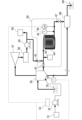
- FIG. 1 is a diagram conceptually showing a geothermal power generation system according to a first embodiment of the present invention.
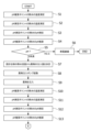
- FIG. 2A is a flowchart illustrating a method for controlling silica-based scale precipitation according to one embodiment of the present invention.
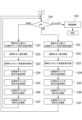
- FIG. 2B is a flowchart illustrating a method for controlling silica-based scale precipitation according to one embodiment of the present invention, and is a diagram illustrating control subsequent to FIG. 2A.
- FIG. 3 is a diagram conceptually showing a geothermal power generation system according to a second embodiment of the present invention.
- FIG. 4 is a diagram conceptually showing a geothermal power generation system according to a third embodiment of the present invention.
- the present invention relates to a geothermal power generation system and a method for controlling silica-based scale precipitation.
- FIG. 1 is a conceptual diagram of a geothermal power generation system according to a first embodiment.
- the geothermal power generation system shown in FIG. 1 is a system that generates power using geothermal fluid as a power source, and mainly includes a production well 5, a steam separator 6, a turbine 7, a condenser 8, a condensate pump 9, and a reinjection well 19.
- the geothermal power generation system further includes a chemical tank 1, a chemical injection pump 2 which is an example of a chemical injection device, a control device 3, a first thermometer 15, a second thermometer 4, and a pH measurement system 20 as components for scale control.
- thick solid arrows represent the flow of geothermal fluid and the components derived from the geothermal fluid, such as steam, hot water, and condensate.
- Thin solid arrows represent the flow of chemicals. Dashed lines represent control signals.
- the production well 5 is a well that draws geothermal fluid, which is hot water, steam, or a mixture of these, from the geothermal reservoir underground to the surface.
- the geothermal fluid drawn from the production well 5 is separated into steam, which is a gas component, and hot water, which is a liquid component, in the steam separator 6.
- the separated steam is guided to the turbine 7 and used to rotate the turbine, which produces electricity in the generator.
- the steam that has done work in the turbine 7 is cooled and condensed in the condenser 8 to become condensed water.
- the condensed water is sent to the cooling tower 10 by the condensate pump 9.
- the hot water separated in the steam separator 6 is optionally guided to the hot water pit 18 via a heat exchanger or the like (not shown) and returned to the reinjection well 19.
- a portion of the hot water guided to the hot water pit 18 may be guided to a facility that uses heat in a later stage, such as a hot spring facility (not shown).
- a second steam separator is provided downstream of the steam separator 6, and the steam separated in the second steam separator heats the low boiling point medium.
- the heated low boiling point medium is used to rotate the second turbine.
- the low boiling point medium is used by repeatedly evaporating and condensing while circulating, and the hot water separated in the steam separator 6 may be used to heat the low boiling point medium.
- geothermal power generation system describes a configuration common to a binary power generation system and a system that operates a turbine using only geothermal steam, and both the binary power generation system and the system that operates a turbine using only geothermal steam are considered to fall within the scope of this invention.
- the pH measurement system 20 and the first thermometer 15 are connected to the steam separator 6.
- the pH measurement system 20 is configured to allow some of the hot water components separated by the steam separator 6 to flow into it. More specifically, the pH measurement system 20 is mainly configured by connecting a pipe branched from the steam separator 6, a spiral pipe 14, and a pH meter 16 in this order.
- a pipe from the condensate pump 9 is connected to the pipe branched from the steam separator 6, and a cleaning agent injection device 13 can be optionally connected to it.
- the hot water can be retained inside the pH measurement system 20 by the first opening and closing valve 12 located between the steam separator 6, the second opening and closing valve 11 located between the condensate pump 9, and the third opening and closing valve 17 located after the pH meter 16. With this configuration, it is possible to measure the pH of the hot water while blocking the movement of substances for a certain period of time.
- the pipe through which the hot water flows can be mainly made of metal, and is preferably made of a corrosion-resistant metal such as a stainless steel pipe.
- the diameter of the pipe through which the hot water flows may be, for example, an outer diameter of about 2 to 12.7 mm.
- the spiral pipe 14 only needs to have a sufficient surface area to reduce the temperature of the high-temperature hot water of about 200°C separated from the steam separator 6 to about 80°C, and there are no particular limitations on the diameter or number of turns of the spiral. However, it is preferable that the spiral pipe 14 is installed in a manner that allows its outer surface to come into contact with the air at room temperature.
- the pH meter 16 only needs to be a device equipped with a commonly used porous glass electrode and capable of measuring a pH in the range of about 5 to 11.
- the operation of the pH measurement system 20 will be described.
- the first open/close valve 12 between the steam separator 6 is opened, and the hot water is introduced into the pH measurement system 20.
- the second open/close valve 11 is kept closed during pH measurement.
- the hot water from the steam separator 6 passes through the spiral tube 14 at high speed, dissipates heat while passing through the spiral tube 14, and reaches the pH meter 16.
- the first open/close valve 12 and the third open/close valve 17 are closed.
- the first thermometer 15 may measure the temperature of the pipe near the pH meter 16 to obtain the temperature of the hot water.
- the first thermometer 15 may be a thermometer that measures the temperature by contacting the pipe, or may be a thermometer that can measure the temperature of the pipe without contact. Alternatively, it may be a thermometer that directly measures the temperature of the hot water rather than the temperature of the pipe.
- the pH of the hot water obtained by the pH meter 16 and the temperature of the hot water obtained by the first thermometer 15 are sent to the control device 3.
- the pH of the hot water obtained by the pH meter 16 and the temperature of the hot water obtained by the first thermometer 15 may be referred to as the pH and temperature of the hot water obtained at the pH measurement point.
- the third on-off valve 17 is opened, and the measured hot water is discharged from inside the pH measurement system 20 to the hot water pit 18.
- the inside of the pH measurement system 20 can be cleaned.
- the first on-off valve 12 is closed, the third on-off valve 17 is opened, and the second on-off valve 11 is opened.
- condensate whose temperature has been reduced to room temperature flows at high pressure into the pipe branched from the steam separator 6.
- the speed of the condensate can be adjusted by the pressure of the condensate pump 9.
- the condensate flowing at high speed can physically peel off scale that has adhered to the pipe or is growing during pH measurement. If scale adhesion is a concern, it can be optionally configured to be able to inject a scale cleaning agent from the cleaning agent injection device 13 into the pipe of the pH measurement system 20.
- cleaning agents include hydrofluoric acid and sodium hydroxide, but there is no limit to specific cleaning agents.
- valves 11, 12, and 17 can be closed while liquids such as condensate, cleaning solution, and tap water remain in the piping of pH measurement system 20 until the next use.
- the detection part of the pH meter be configured so that it can be stored in the KCl solution, which is the solution of the reference electrode of the pH meter.
- the second thermometer 4 measures the temperature of the geothermal fluid between the production well 5 and the brackish water separator 6. More specifically, the temperature of the geothermal fluid can be obtained by measuring the temperature of the pipe through which the geothermal fluid flows between the production well 5 and the brackish water separator 6.
- the second thermometer 4 may also be configured similarly to the first thermometer 15, and it is also possible to obtain the temperature of the geothermal fluid by other methods as described for the first thermometer 15.
- the temperature of the hot water obtained by the second thermometer 4 is sent to the control device 3.
- the temperature obtained by the second thermometer 4 is used to estimate the pH of the geothermal fluid at the location where the second thermometer 4 is installed. For this reason, in this specification, the temperature obtained by the second thermometer 4 may be referred to as the temperature obtained at the pH estimation point.
- the chemical tank 1 and the chemical injection pump 2 are connected in such a manner that a chemical capable of adjusting the pH, typically an alkaline chemical, can be injected into the geothermal fluid flowing through the geothermal power generation system.
- a chemical capable of adjusting the pH typically an alkaline chemical
- the chemical injection pump 2 is connected to the piping between the production well 5 and the steam separator 6.
- the start and stop of chemical injection, as well as the amount of chemical injection, can be controlled by the control device 3.
- the control device 3 is electrically connected to the pH meter 16, the first thermometer 15, and the second thermometer 4 to acquire actual measurement data from these, and performs calculations based on the actual measurement data to estimate the pH at the pH estimation point, which is the location where the second thermometer 4 is installed. In addition, based on the results of these calculations, it can start and stop the operation of the drug injection pump 2 and calculate the injection amount, and issue commands to the drug injection pump 2. Therefore, the control device 3 may be a computer incorporating algorithms related to these calculations. Details of the calculations and commands will be described later.
- the method for controlling silica-based scale precipitation relates to a method that estimates the pH value at a specific location in the geothermal power generation system and controls the injection of chemicals into the geothermal fluid so as to maintain the estimated value at 8 or more and 9 or less.
- the method for controlling silica-based scale precipitation includes the following steps. (a) measuring a temperature of a geothermal fluid at a pH estimation point in a geothermal power generation system; (b) A process for extracting a portion of the hot water separated in the steam separator, releasing heat, and measuring the pH and temperature. (c) A process for estimating the pH of the geothermal fluid at the pH estimation point based on the measurement results of steps (a) and (b). (d) A process for determining whether or not to inject an alkaline agent into the geothermal fluid based on the estimation result of step (c).
- FIGS 2A and 2B are flow charts explaining an example of a method for controlling silica-based scale precipitation. The following will be explained with reference to the conceptual diagram and flow chart of the geothermal power generation system according to the first embodiment shown in Figure 1.
- the geothermal fluid in step (c) may be a mixture of steam and hot water, or may be hot water, depending on the position of the pH estimation point, and hot water is shown as an example in the flow chart. Both are collectively referred to as geothermal fluid.
- silica-based scale precipitation control method it is preferable to carry out the silica-based scale precipitation control method periodically, for example, once a month or once every two months.
- the frequency of implementation can be increased or decreased as needed.
- step (a) the temperature of the geothermal fluid at the pH estimation point of the geothermal power generation system is measured.
- the pH estimation point is between the production well 5 and the steam separator 6, and the temperature of the pipe through which the geothermal fluid flows at the pH estimation point can be measured by the second thermometer 4.
- Step (a) corresponds to S1 in the flowchart of FIG. 2A.
- step (b) a portion of the hot water separated in the steam separator 6 is extracted, heat is released, and the pH and temperature are measured.
- step (b) the pH measurement system 20 is operated, and the pH of the hot water is measured by the pH meter 16. Also, the first thermometer 15 measures the temperature of the pipe through which the hot water flows, and the temperature of the hot water can be obtained. Step (b) corresponds to S2 and S3 in the flowchart of FIG. 2A.
- step (c) the pH of the geothermal fluid at the pH estimation point is estimated based on the measurement results of steps (a) and (b). Specifically, the measurement values obtained in steps (a) and (b) are sent to the control device 3. Then, the pH of the geothermal fluid at the pH estimation point can be estimated based on an algorithm pre-installed in the control device 3.
- the algorithm may be capable of calculating the pH of the geothermal fluid at the pH estimation point based on a relationship between temperature and pH. The relationship between temperature and pH can be calculated using commercially available software such as The Geochemist's Workbench (registered trademark).
- Step (c) corresponds to S4 in the flowchart of FIG. 2A.
- step (d) the necessity of injecting an alkaline agent into the geothermal fluid is determined based on the estimation result of step (c). More specifically, whether or not to inject an alkaline agent into the geothermal fluid is determined depending on whether the estimated pH value is less than the lower limit of a predetermined range of an alkaline region where scale is unlikely to form, or is equal to or greater than the lower limit.
- the predetermined range of an alkaline region where scale is unlikely to form is not particularly limited, but can be set by a person skilled in the art within the range of pH 8 to 11, and can be set to, for example, pH 8 to 9.
- Step (d) corresponds to S5 in the flowchart of FIG. 2A. If the estimated pH value is 8 or more, it is determined that the geothermal water has properties that allow for the suppression of scale deposition, and power generation is continued (S6).
- the control device 3 ends control without sending a command to the chemical injection pump (END).
- step (d) if the estimated pH value is less than 8, it is determined that an alkaline agent needs to be injected into the geothermal fluid, and the method further includes the following steps (e) to (j): (e) if it is determined in step (d) that an alkaline agent needs to be injected, determining the amount of alkaline agent to be injected; (f) based on the determination result of step (e), injecting an alkaline agent into the geothermal fluid; (g) after completion of step (f), measuring the temperature of the geothermal fluid at the pH estimation point; (h) after completion of step (f), extracting a portion of the hot water separated in the steam separator, releasing heat and measuring the pH and temperature; (i) based on the measurement results of steps (g) and (h), estimating the pH of the geothermal fluid at the pH estimation point; and (j) based on the estimation result of step (i), determining whether to increase, decrease, or maintain the amount of alkaline agent injected into the
- step (e) the amount of alkaline agent to be injected is determined.
- the alkaline agent may be, but is not limited to, sodium hydroxide, potassium hydroxide, sodium bicarbonate, or the like.
- the amount of alkaline agent to be injected can be calculated based on the estimated pH value obtained in step (c) and the hot water flow rate of the design specifications specific to the geothermal power generation system at the pH estimation point, so that the target pH value of the hot water after injection is 8 or more and 9 or less.
- the calculation can be performed by an algorithm pre-installed in the control device 3.
- Step (e) corresponds to S7 in the flowchart.
- step (f) an alkaline agent is injected into the geothermal fluid based on the result of the determination in step (e).
- the alkaline agent can be injected by operating the agent injection pump 2 using the control device 3.
- Step (f) corresponds to S8 and S9 in the flowchart.
- step (g) after the completion of step (f), the temperature at the pH estimation point is obtained in order to obtain a pH estimation value again.
- the operation may be the same as in step (a).
- step (h) the pH and temperature at the pH measurement point are obtained in order to obtain a pH estimation value again after the completion of step (f).
- step (b) in which a portion of the hot water separated in the steam separator is extracted, heat is released, and the pH and temperature are measured.
- Step (g) corresponds to S10 in the flow chart
- step (h) corresponds to S11 and S12.
- step (i) the pH of the geothermal fluid at the pH estimation point is estimated based on the measurement results in steps (g) and (h).
- Step (i) corresponds to S13 in the flowchart, and allows for the estimation of the pH after the alkaline agent is injected.
- step (j) it is determined whether to increase, decrease, or maintain the amount of alkaline chemicals injected into the geothermal fluid based on the results of the estimation in step (i).
- the estimated pH value is divided into three cases: when the estimated pH value is below a predetermined range in the alkaline region (i.e., below 8), when it is within a predetermined range in the alkaline region (i.e., between 8 and 9), and when it exceeds a predetermined range in the alkaline region (i.e., when it exceeds 9), and control is performed for each case.
- the flow chart proceeds to A in the flow chart in FIG. 2B.
- Step (j) corresponds to S14 in the flow chart in FIG. 2B.
- the control device 3 ends the control (END) without sending any additional command to the chemical injection pump 2. Therefore, the injection of the amount of chemicals determined in step (e) continues, and power generation continues.
- step (j) if the estimated pH value is below a predetermined preferred range, for example, below 8, it is determined to increase the alkaline agent injection amount, and the method further includes the following steps: (k) determining the amount of alkaline agent to be injected after the increase in the alkaline agent; (l) injecting an alkaline agent into the geothermal fluid based on the result of the determination in step (k); (m) measuring the temperature of the geothermal fluid at the pH estimation point after completion of step (l); (n) extracting a portion of the hot water separated in the steam separator, releasing heat and measuring the pH and temperature after completion of step (l); and (o) estimating the pH of the geothermal fluid at the pH estimation point based on the measurement results of steps (m) and (n).
- the operations including steps (k) to (o) can be referred to as pH increase/estimation operations.
- Steps (k) and (l) are performed when the estimated pH value is less than 8, i.e., when the amount of alkaline agent injected determined in step (e) is not sufficient to raise the pH value at the estimated pH point. In S14, if the estimated pH value is less than 8, proceed to S21.
- step (k) the injection amount after the increase in the alkaline agent is determined. If the estimated pH value is less than 8, it is presumed that the actual hot water flow rate at the pH estimation point is greater than the hot water flow rate of the design specifications at the pH estimation point used in the calculation in step (e). Therefore, the actual hot water flow rate at the pH estimation point is calculated from the injection amount of the alkaline agent determined in step (e) and the estimated pH value obtained in step (j). The calculation can be performed by an algorithm pre-installed in the control device 3. Then, the injection amount after the increase in the alkaline agent can be determined from the actual hot water flow rate at the pH estimation point obtained by calculation. Step (k) corresponds to S21 and S22 in the flowchart.
- Step (l) an alkaline agent is injected into the geothermal fluid based on the results of the determination in step (k).
- Step (l) corresponds to S23 in the flowchart.
- step (m) after the completion of step (l), the temperature at the pH estimation point is obtained again to obtain a pH estimation value.
- the operation may be the same as in step (a).
- step (n) after the completion of step (l), the pH and temperature at the pH measurement point are obtained again to obtain a pH estimation value.
- step (b) where a portion of the hot water separated in the steam separator 6 is extracted, heat is released, and the pH and temperature are measured.
- Step (m) corresponds to S24 in the flow chart
- step (n) corresponds to S25 and S26.
- step (o) the pH of the geothermal fluid at the pH estimation point is estimated based on the measurement results of steps (m) and (n).
- Step (o) corresponds to S27 in the flowchart.
- step (j) if the estimated pH value exceeds a predetermined preferred range, for example, 9, it is decided to reduce the amount of alkaline agent to be injected, and the method further includes the following steps.
- (p) determining the amount of alkaline agent to be injected after reduction;
- (q) injecting an alkaline agent into the geothermal fluid based on the result of the determination in step (p);
- (r) measuring the temperature of the geothermal fluid at the pH estimation point after completion of step (q);
- (t) estimating the pH of the geothermal fluid at the pH estimation point based on the measurement results of steps (r) and (s).
- the operations including steps (p) to (t) can be referred to as pH reduction/estimation operations.
- Steps (p) to (t) are performed if the estimated pH value in S14 exceeds 9, i.e., if the amount of alkaline agent determined in step (e) increases the pH of the hot water beyond the appropriate range. If the estimated pH value in S14 exceeds 9, proceed to S31.
- step (p) the injection amount of the alkaline agent after reduction is determined. If the estimated pH value exceeds 9, it is estimated that the actual hot water flow rate at the pH estimation point is smaller than the hot water flow rate of the design specification at the pH estimation point used in the calculation in step (e). Therefore, the actual hot water flow rate at the pH estimation point is calculated from the injection amount of the alkaline agent determined in step (e) and the estimated pH value obtained in step (j). The calculation can be performed by an algorithm pre-installed in the control device 3. Then, the injection amount of the alkaline agent after reduction can be determined from the actual hot water flow rate at the pH estimation point obtained by calculation. Step (p) corresponds to S31 and S32 in the flowchart.
- Step (q) an alkaline agent is injected into the geothermal fluid based on the results of the determination in step (p).
- Step (q) corresponds to S33 in the flowchart.
- step (r) after the completion of step (q), the temperature at the pH estimation point is obtained in order to obtain a pH estimation value again.
- the operation may be the same as in step (a).
- step (p) after the completion of step (q), the pH and temperature at the pH measurement point are obtained in order to obtain a pH estimation value again.
- step (b) in which a portion of the hot water separated in the steam separator 6 is extracted, heat is released, and the pH and temperature are measured.
- Step (r) corresponds to S34 in the flow chart
- step (s) corresponds to S35 and S36.
- step (t) the pH of the geothermal fluid at the pH estimation point is estimated based on the measurement results of steps (r) and (s).
- Step (t) corresponds to S37 in the flowchart.
- the geothermal power generation system of the first embodiment by obtaining an estimated pH value between the production well 5 and the brackish water separator 6 and injecting an alkaline agent into the geothermal fluid between the production well 5 and the brackish water separator 6, it is possible to control the pH of the geothermal fluid and suppress the buildup of scale.
- FIG. 3 is a conceptual diagram of a geothermal power generation system according to a second embodiment of the present invention.
- the geothermal power generation system shown in FIG. 3 differs from the first embodiment in that a second thermometer 34 is provided at the hot water outlet of the brackish water separator 36, and that a chemical injection pump 32 is configured to inject a chemical into the hot water section in the brackish water separator 36.
- the other configurations are the same as those of the first embodiment.
- each step of the silica-based scale precipitation control method is also the same as those of the first embodiment.
- the hot water section in the brackish water separator 36 refers to the part through which the hot water obtained by separating the steam in the geothermal fluid flowing into the brackish water separator 36 flows.
- FIG. 4 is a conceptual diagram of a geothermal power generation system according to a third embodiment of the present invention.
- the geothermal power generation system shown in FIG. 4 differs from the first embodiment in that a second thermometer 64 is provided at the entrance of the reinjection well 79, and a hot water pit is not provided.
- the rest of the configuration is the same as in the first embodiment.
- each process of the silica-based scale precipitation control method is also the same as in the first embodiment.
- the entrance to the reinjection well 79 is set as the pH estimation point, and the temperature of the hot water entering the reinjection well 79 is set as the parameter for determining the amount of alkaline chemicals to be injected.
- This makes it possible to prevent scale formation in the piping leading up to the reinjection well 79. This provides the advantage of eliminating the need for the scale precipitation process in the hot water pit, which was previously essential, and eliminating the need to install a hot water pit.
Landscapes
- Engineering & Computer Science (AREA)
- Chemical & Material Sciences (AREA)
- Combustion & Propulsion (AREA)
- Life Sciences & Earth Sciences (AREA)
- Mechanical Engineering (AREA)
- General Engineering & Computer Science (AREA)
- Water Supply & Treatment (AREA)
- Sustainable Energy (AREA)
- Organic Chemistry (AREA)
- Environmental & Geological Engineering (AREA)
- Hydrology & Water Resources (AREA)
- Health & Medical Sciences (AREA)
- Analytical Chemistry (AREA)
- Medicinal Chemistry (AREA)
- Physics & Mathematics (AREA)
- Food Science & Technology (AREA)
- Biochemistry (AREA)
- General Health & Medical Sciences (AREA)
- General Physics & Mathematics (AREA)
- Immunology (AREA)
- Pathology (AREA)
- Investigating Or Analyzing Materials By The Use Of Electric Means (AREA)
- Preventing Corrosion Or Incrustation Of Metals (AREA)
Abstract
Description
[1] 生産井と、
前記生産井から得られる地熱流体を蒸気と熱水に分離する汽水分離器と、
前記汽水分離器で分離された蒸気により回転するタービンと、
前記汽水分離器及び/またはタービンを経た地熱流体を還流する還元井と、
前記汽水分離器で分離された熱水の一部を抽出し、当該熱水のpHを測定するpH測定システム、及び当該熱水の温度を測定する第1の温度計と、
地熱流体にアルカリ性薬剤を注入する注入装置と、
前記アルカリ性薬剤の注入部、前記汽水分離器出口、または還元井入口から選択されるpH推算ポイントの地熱流体の温度を測定する第2の温度計と、
前記pH測定システム、第1の温度計、及び第2の温度計の測定結果に基づき、前記注入装置によるアルカリ性薬剤の注入を制御する制御装置と
を含む、地熱発電システムであって
前記pH測定システムが、螺旋管と、pH計とを備え、開閉バルブを介して前記タービン下流の復水ポンプに接続されている、地熱発電システム。
[2] 前記pH測定システムが、洗浄剤の注入部をさらに含む、[1]に記載のシステム。
[3] 前記注入装置が、前記生産井と前記汽水分離器の間の配管に接続される、[1]に記載のシステム。
[4] 前記第2の温度計が、前記生産井と前記汽水分離器の間の配管に設けられる[3]に記載のシステム。
[5] 前記第2の温度計が、前記還元井入口に設けられる[3]に記載のシステム。
[6] 前記注入装置が、前記汽水分離器の熱水部に接続される[1]に記載のシステム。
[7] (a)地熱発電システムのpH推算ポイントにおける地熱流体の温度を測定する工程と、
(b)汽水分離器で分離された熱水の一部を抽出し、放熱してpH及び温度を測定する工程と、
(c)前記工程(a)及び(b)の測定結果に基づき、前記pH推算ポイントにおける地熱流体のpHを推算する工程と、
(d)前記工程(c)の推算結果に基づき、地熱流体へのアルカリ性薬剤注入の要否を決定する工程と
を含む、シリカ系スケール析出制御方法。
[8] 前記工程(d)において、pHがアルカリ性領域の所定の範囲未満の場合に、前記地熱流体へのアルカリ性薬剤注入が必要と決定する、[7]に記載の方法。
[9] (e)前記工程(d)において、アルカリ性薬剤注入が必要と決定された場合に、アルカリ性薬剤の注入量を決定する工程と、
(f)前記工程(e)の決定結果に基づき、前記地熱流体にアルカリ性薬剤を注入する工程と、
(g)前記工程(f)の終了後、前記pH推算ポイントにおける地熱流体の温度を測定する工程と、
(h)前記工程(f)の終了後、汽水分離器で分離された熱水の一部を抽出し、放熱してpH及び温度を測定する工程と、
(i)前記工程(g)及び(h)の測定結果に基づき、前記pH推算ポイントにおける地熱流体のpHを推算する工程と、
(j)前記工程(i)の推算結果に基づき、前記地熱流体へのアルカリ性薬剤注入量の増減または維持を決定する工程と
をさらに含む[7]に記載の方法。
[10] 前記工程(j)において、pHがアルカリ性領域の所定の範囲未満の場合にアルカリ性薬剤注入量を増加すると決定し、pHがアルカリ性領域の所定の範囲を超える場合にアルカリ性薬剤注入量を低減すると決定し、pHがアルカリ性領域の所定の範囲内の場合にアルカリ性薬剤注入量を維持すると決定する、[9]に記載の方法。
[11] 前記工程(j)において、アルカリ性薬剤注入量を増加すると決定された場合に、
(k)アルカリ性薬剤の増加後の注入量を決定する工程と、
(l)前記工程(k)の決定結果に基づき、地熱流体にアルカリ性薬剤を注入する工程と、
(m)前記工程(l)の終了後、前記pH推算ポイントにおける地熱流体の温度を測定する工程と、
(n)前記工程(l)の終了後、汽水分離器で分離された熱水の一部を抽出し、放熱してpH及び温度を測定する工程と、
(o)前記工程(m)及び(n)の測定結果に基づき、前記pH推算ポイントにおける地熱流体のpHを推算する工程と
を含む、pH上昇・推算操作を行い、
前記工程(j)において、アルカリ性薬剤注入量を低減すると決定された場合に、
(p)アルカリ性薬剤の低減後の注入量を決定する工程と、
(q)前記工程(p)の決定結果に基づき、地熱流体にアルカリ性薬剤を注入する工程と、
(r)前記工程(q)の終了後、前記pH推算ポイントにおける地熱流体の温度を測定する工程と、
(s)前記工程(q)の終了後、汽水分離器で分離された熱水の一部を抽出し、放熱してpH及び温度を測定する工程と、
(t)前記工程(r)及び(s)の測定結果に基づき、前記pH推算ポイントにおける地熱流体のpHを推算する工程と
を含む、pH低下・推算操作を行う、[10]に記載の方法。
[12] 前記工程(o)または工程(q)の推算結果に基づき、前記地熱流体へのアルカリ性薬剤注入量の増減または維持を決定する工程をさらに含み、pH推算値が所定のアルカリ性領域の所定の範囲に達するまで、前記pH上昇・推算操作または前記pH低下・推算操作を繰り返す、[11]に記載の方法。
(a)地熱発電システムのpH推算ポイントにおける地熱流体の温度を測定する工程と、
(b)汽水分離器で分離された熱水の一部を抽出し、放熱してpH及び温度を測定する工程
(c)前記工程(a)及び(b)の測定結果に基づき、前記pH推算ポイントにおける地熱流体のpHを推算する工程
(d)前記工程(c)の推算結果に基づき、前記地熱流体にアルカリ性薬剤注入の要否を決定する工程
(e)前記工程(d)において、アルカリ性薬剤注入が必要と決定された場合に、アルカリ性薬剤の注入量を決定する工程
(f)前記工程(e)の決定結果に基づき、前記地熱流体にアルカリ性薬剤を注入する工程
(g)前記工程(f)の終了後、前記pH推算ポイントにおける地熱流体の温度を測定する工程
(h)前記工程(f)の終了後、汽水分離器で分離された熱水の一部を抽出し、放熱してpH及び温度を測定する工程
(i)前記工程(g)及び(h)の測定結果に基づき、前記pH推算ポイントにおける地熱流体のpHを推算する工程
(j)前記工程(i)の推算結果に基づき、前記地熱流体へのアルカリ性薬剤注入量の増減、または維持を決定する工程
(k)アルカリ性薬剤の増加後の注入量を決定する工程
(l)前記工程(k)の決定結果に基づき、前記地熱流体にアルカリ性薬剤を注入する工程
(m)前記工程(l)の終了後、前記pH推算ポイントにおける地熱流体の温度を測定する工程
(n)前記工程(l)の終了後、汽水分離器で分離された熱水の一部を抽出し、放熱してpH及び温度を測定する工程
(o)前記工程(m)及び(n)の測定結果に基づき、前記pH推算ポイントにおける地熱流体のpHを推算する工程
これらの工程(k)から(o)を含む操作を、pH上昇・推算操作ということができる。
(p)アルカリ性薬剤の低減後の注入量を決定する工程
(q)前記工程(p)の決定結果に基づき、前記地熱流体にアルカリ性薬剤を注入する工程
(r)前記工程(q)の終了後、前記pH推算ポイントにおける地熱流体の温度を測定する工程
(s)前記工程(q)の終了後、汽水分離器で分離された熱水の一部を抽出し、放熱してpH及び温度を測定する工程
(t)前記工程(r)及び(s)の測定結果に基づき、前記pH推算ポイントにおける地熱流体のpHを推算する工程
これらの工程(p)から(t)を含む操作を、pH低下・推算操作ということができる。
3、33、63 制御装置、4、34、64 第2の温度計、5、35、65 生産井
6、36、66 汽水分離器、7、37、67 タービン 8、38、68 復水器
9、39、69 復水ポンプ、10、40、70 冷却塔、
11、41、71 第2の開閉バルブ、12、42、72 第1の開閉バルブ、
13、43、73 洗浄剤注入装置、14、44、74 螺旋管
15、45、75 第1の温度計、16、46、76 pH計
17、47、77 第3の開閉バルブ、18、48 熱水ピット
19、49、79 還元井
Claims (12)
- 生産井と、
前記生産井から得られる地熱流体を蒸気と熱水に分離する汽水分離器と、
前記汽水分離器で分離された蒸気により回転するタービンと、
前記汽水分離器及び/またはタービンを経た地熱流体を還流する還元井と、
前記汽水分離器で分離された熱水の一部を抽出し、当該熱水のpHを測定するpH測定システム、及び当該熱水の温度を測定する第1の温度計と、
地熱流体にアルカリ性薬剤を注入する注入装置と、
前記アルカリ性薬剤の注入部、前記汽水分離器出口、または還元井入口から選択されるpH推算ポイントの地熱流体の温度を測定する第2の温度計と、
前記pH測定システム、第1の温度計、及び第2の温度計の測定結果に基づき、前記注入装置によるアルカリ性薬剤の注入を制御する制御装置と
を含む、地熱発電システムであって
前記pH測定システムが、螺旋管と、pH計とを備え、開閉バルブを介して前記タービン下流の復水ポンプに接続されている、地熱発電システム。 - 前記pH測定システムが、洗浄剤の注入部をさらに含む、請求項1に記載のシステム。
- 前記注入装置が、前記生産井と前記汽水分離器の間の配管に接続される、請求項1に記載のシステム。
- 前記第2の温度計が、前記生産井と前記汽水分離器の間の配管に設けられる請求項3に記載のシステム。
- 前記第2の温度計が、前記還元井入口に設けられる請求項3に記載のシステム。
- 前記注入装置が、前記汽水分離器の熱水部に接続される請求項1に記載のシステム。
- (a)地熱発電システムのpH推算ポイントにおける地熱流体の温度を測定する工程と、
(b)汽水分離器で分離された熱水の一部を抽出し、放熱してpH及び温度を測定する工程と、
(c)前記工程(a)及び(b)の測定結果に基づき、前記pH推算ポイントにおける地熱流体のpHを推算する工程と、
(d)前記工程(c)の推算結果に基づき、地熱流体へのアルカリ性薬剤注入の要否を決定する工程と
を含む、シリカ系スケール析出制御方法。 - 前記工程(d)において、pHがアルカリ性領域の所定の範囲未満の場合に、前記地熱流体へのアルカリ性薬剤注入が必要と決定する、請求項7に記載の方法。
- (e)前記工程(d)において、アルカリ性薬剤注入が必要と決定された場合に、アルカリ性薬剤の注入量を決定する工程と、
(f)前記工程(e)の決定結果に基づき、前記地熱流体にアルカリ性薬剤を注入する工程と、
(g)前記工程(f)の終了後、前記pH推算ポイントにおける地熱流体の温度を測定する工程と、
(h)前記工程(f)の終了後、汽水分離器で分離された熱水の一部を抽出し、放熱してpH及び温度を測定する工程と、
(i)前記工程(g)及び(h)の測定結果に基づき、前記pH推算ポイントにおける地熱流体のpHを推算する工程と、
(j)前記工程(i)の推算結果に基づき、前記地熱流体へのアルカリ性薬剤注入量の増減または維持を決定する工程と
をさらに含む請求項7に記載の方法。 - 前記工程(j)において、pHがアルカリ性領域の所定の範囲未満の場合にアルカリ性薬剤注入量を増加すると決定し、pHがアルカリ性領域の所定の範囲を超える場合にアルカリ性薬剤注入量を低減すると決定し、pHがアルカリ性領域の所定の範囲内の場合にアルカリ性薬剤注入量を維持すると決定する、請求項9に記載の方法。
- 前記工程(j)において、アルカリ性薬剤注入量を増加すると決定された場合に、
(k)アルカリ性薬剤の増加後の注入量を決定する工程と、
(l)前記工程(k)の決定結果に基づき、地熱流体にアルカリ性薬剤を注入する工程と、
(m)前記工程(l)の終了後、前記pH推算ポイントにおける地熱流体の温度を測定する工程と、
(n)前記工程(l)の終了後、汽水分離器で分離された熱水の一部を抽出し、放熱してpH及び温度を測定する工程と、
(o)前記工程(m)及び(n)の測定結果に基づき、前記pH推算ポイントにおける地熱流体のpHを推算する工程と
を含む、pH上昇・推算操作を行い、
前記工程(j)において、アルカリ性薬剤注入量を低減すると決定された場合に、
(p)アルカリ性薬剤の低減後の注入量を決定する工程と、
(q)前記工程(p)の決定結果に基づき、地熱流体にアルカリ性薬剤を注入する工程と、
(r)前記工程(q)の終了後、前記pH推算ポイントにおける地熱流体の温度を測定する工程と、
(s)前記工程(q)の終了後、汽水分離器で分離された熱水の一部を抽出し、放熱してpH及び温度を測定する工程と、
(t)前記工程(r)及び(s)の測定結果に基づき、前記pH推算ポイントにおける地熱流体のpHを推算する工程と
を含む、pH低下・推算操作を行う、請求項10に記載の方法。 - 前記工程(o)または工程(q)の推算結果に基づき、前記地熱流体へのアルカリ性薬剤注入量の増減または維持を決定する工程をさらに含み、pH推算値が所定のアルカリ性領域の所定の範囲に達するまで、前記pH上昇・推算操作または前記pH低下・推算操作を繰り返す、請求項11に記載の方法。
Priority Applications (2)
| Application Number | Priority Date | Filing Date | Title |
|---|---|---|---|
| JP2024549928A JP7754341B2 (ja) | 2022-09-29 | 2023-08-31 | 地熱発電システム及びシリカ系スケール析出制御方法 |
| US18/820,478 US12571378B2 (en) | 2022-09-29 | 2024-08-30 | Geothermal power generation system and silica scale deposition control method |
Applications Claiming Priority (2)
| Application Number | Priority Date | Filing Date | Title |
|---|---|---|---|
| JP2022-156629 | 2022-09-29 | ||
| JP2022156629 | 2022-09-29 |
Related Child Applications (1)
| Application Number | Title | Priority Date | Filing Date |
|---|---|---|---|
| US18/820,478 Continuation US12571378B2 (en) | 2022-09-29 | 2024-08-30 | Geothermal power generation system and silica scale deposition control method |
Publications (1)
| Publication Number | Publication Date |
|---|---|
| WO2024070490A1 true WO2024070490A1 (ja) | 2024-04-04 |
Family
ID=90477260
Family Applications (1)
| Application Number | Title | Priority Date | Filing Date |
|---|---|---|---|
| PCT/JP2023/031960 Ceased WO2024070490A1 (ja) | 2022-09-29 | 2023-08-31 | 地熱発電システム及びシリカ系スケール析出制御方法 |
Country Status (3)
| Country | Link |
|---|---|
| US (1) | US12571378B2 (ja) |
| JP (1) | JP7754341B2 (ja) |
| WO (1) | WO2024070490A1 (ja) |
Citations (4)
| Publication number | Priority date | Publication date | Assignee | Title |
|---|---|---|---|---|
| JP2011196197A (ja) * | 2010-03-17 | 2011-10-06 | Fuji Electric Co Ltd | スケール抑制方法及び発電システム |
| WO2013027822A1 (ja) * | 2011-08-25 | 2013-02-28 | 富士電機株式会社 | スケール抑制方法及び地熱発電装置 |
| CN113620478A (zh) * | 2021-09-14 | 2021-11-09 | 重庆华捷地热能开发有限公司 | 一种弱碱化降压强化析垢方法 |
| WO2023074697A1 (ja) * | 2021-10-25 | 2023-05-04 | 富士電機株式会社 | シリカスケール生成量の予測方法 |
Family Cites Families (4)
| Publication number | Priority date | Publication date | Assignee | Title |
|---|---|---|---|---|
| WO2010038479A1 (ja) * | 2008-10-03 | 2010-04-08 | 富士電機システムズ株式会社 | 蒸気性状自動測定装置及び地熱発電装置 |
| JP5839030B2 (ja) | 2011-04-19 | 2016-01-06 | 富士電機株式会社 | スケール抑制方法及び地熱発電装置 |
| JP2015090147A (ja) | 2013-11-07 | 2015-05-11 | 三菱日立パワーシステムズ株式会社 | 地熱発電システム及び地熱発電システムのスケール防止方法 |
| JP2018167204A (ja) | 2017-03-30 | 2018-11-01 | 栗田工業株式会社 | 地熱水のシリカスケール防止方法及びシリカスケール防止剤 |
-
2023
- 2023-08-31 JP JP2024549928A patent/JP7754341B2/ja active Active
- 2023-08-31 WO PCT/JP2023/031960 patent/WO2024070490A1/ja not_active Ceased
-
2024
- 2024-08-30 US US18/820,478 patent/US12571378B2/en active Active
Patent Citations (4)
| Publication number | Priority date | Publication date | Assignee | Title |
|---|---|---|---|---|
| JP2011196197A (ja) * | 2010-03-17 | 2011-10-06 | Fuji Electric Co Ltd | スケール抑制方法及び発電システム |
| WO2013027822A1 (ja) * | 2011-08-25 | 2013-02-28 | 富士電機株式会社 | スケール抑制方法及び地熱発電装置 |
| CN113620478A (zh) * | 2021-09-14 | 2021-11-09 | 重庆华捷地热能开发有限公司 | 一种弱碱化降压强化析垢方法 |
| WO2023074697A1 (ja) * | 2021-10-25 | 2023-05-04 | 富士電機株式会社 | シリカスケール生成量の予測方法 |
Also Published As
| Publication number | Publication date |
|---|---|
| JPWO2024070490A1 (ja) | 2024-04-04 |
| US12571378B2 (en) | 2026-03-10 |
| JP7754341B2 (ja) | 2025-10-15 |
| US20240426283A1 (en) | 2024-12-26 |
Similar Documents
| Publication | Publication Date | Title |
|---|---|---|
| WO2012144277A1 (ja) | スケール抑制方法及び地熱発電装置 | |
| JP5125970B2 (ja) | 地熱流体利用システムのスケール付着監視装置 | |
| JP6056183B2 (ja) | スケール抑制装置、その装置を用いた地熱発電システム及びスケール抑制方法 | |
| von Hirtz | Silica scale control in geothermal plants—Historical perspective and current technology | |
| JP5563854B2 (ja) | スケール抑制方法及び発電システム | |
| JP7754341B2 (ja) | 地熱発電システム及びシリカ系スケール析出制御方法 | |
| JP5519920B2 (ja) | Pwr発電所二次冷却系の水処理システム及びその方法 | |
| US20150210567A1 (en) | Scale suppression apparatus, geothermal power generation system using the same, and scale suppression method | |
| WO2011045878A1 (ja) | 水質診断方法及びその方法を用いたヒートポンプ利用の給湯システム | |
| CN114484408B (zh) | 一种火力发电厂混合式乏汽回收器的控制系统及方法 | |
| JP2008190933A (ja) | Pwr型原子力発電所における二次冷却材中のイオン不純物濃度評価方法及びこの評価方法を用いたpwr型原子力発電所の二次冷却系統の運転システム | |
| JP2018146224A (ja) | 冷却塔システム | |
| JP2014159914A (ja) | 補給水系統制御装置、及び補給水系統制御方法 | |
| JP5632786B2 (ja) | 排熱回収ボイラ | |
| JP2018146226A (ja) | 冷却塔システム | |
| JP7769925B2 (ja) | シリカ過飽和流体のpH推算装置及びpH推算方法 | |
| WO2025033007A1 (ja) | 蒸気タービンシステム及び地熱発電プラント並びに蒸気タービンシステムの運転方法 | |
| JP2026049588A (ja) | スケール抑制方法、スケール抑制装置、地熱発電システム及び流体利用システム | |
| CN104326547A (zh) | 一种燃煤机组锅炉高压给水微氧精准控制方法及装置 | |
| JP4442764B2 (ja) | ドラムボイラおよびドラムボイラを備えた排熱回収ボイラ | |
| JP4873919B2 (ja) | 鉄イオン注入方法及び鉄イオン注入量制御装置 | |
| JP7095044B2 (ja) | ボイラの化学洗浄方法 | |
| JP2012255627A (ja) | ボイラのブロー率算出方法及びブロー制御方法 | |
| CN202883027U (zh) | 余热发电系统 | |
| CN108548169A (zh) | 一种联合循环发电机组锅炉停用保护系统及使用方法 |
Legal Events
| Date | Code | Title | Description |
|---|---|---|---|
| 121 | Ep: the epo has been informed by wipo that ep was designated in this application |
Ref document number: 23871730 Country of ref document: EP Kind code of ref document: A1 |
|
| ENP | Entry into the national phase |
Ref document number: 2024549928 Country of ref document: JP Kind code of ref document: A |
|
| WWE | Wipo information: entry into national phase |
Ref document number: 12024552054 Country of ref document: PH |
|
| WWE | Wipo information: entry into national phase |
Ref document number: 814215 Country of ref document: NZ |
|
| NENP | Non-entry into the national phase |
Ref country code: DE |
|
| 122 | Ep: pct application non-entry in european phase |
Ref document number: 23871730 Country of ref document: EP Kind code of ref document: A1 |