WO2024070482A1 - 制御装置、および非一時的なコンピュータ可読媒体 - Google Patents
制御装置、および非一時的なコンピュータ可読媒体 Download PDFInfo
- Publication number
- WO2024070482A1 WO2024070482A1 PCT/JP2023/031855 JP2023031855W WO2024070482A1 WO 2024070482 A1 WO2024070482 A1 WO 2024070482A1 JP 2023031855 W JP2023031855 W JP 2023031855W WO 2024070482 A1 WO2024070482 A1 WO 2024070482A1
- Authority
- WO
- WIPO (PCT)
- Prior art keywords
- opening
- switch
- signal
- manner
- closing
- Prior art date
- Legal status (The legal status is an assumption and is not a legal conclusion. Google has not performed a legal analysis and makes no representation as to the accuracy of the status listed.)
- Ceased
Links
Images


Classifications
-
- B—PERFORMING OPERATIONS; TRANSPORTING
- B60—VEHICLES IN GENERAL
- B60J—WINDOWS, WINDSCREENS, NON-FIXED ROOFS, DOORS, OR SIMILAR DEVICES FOR VEHICLES; REMOVABLE EXTERNAL PROTECTIVE COVERINGS SPECIALLY ADAPTED FOR VEHICLES
- B60J1/00—Windows; Windscreens; Accessories therefor
- B60J1/08—Windows; Windscreens; Accessories therefor arranged at vehicle sides
- B60J1/12—Windows; Windscreens; Accessories therefor arranged at vehicle sides adjustable
- B60J1/16—Windows; Windscreens; Accessories therefor arranged at vehicle sides adjustable slidable
- B60J1/17—Windows; Windscreens; Accessories therefor arranged at vehicle sides adjustable slidable vertically
-
- B—PERFORMING OPERATIONS; TRANSPORTING
- B60—VEHICLES IN GENERAL
- B60R—VEHICLES, VEHICLE FITTINGS, OR VEHICLE PARTS, NOT OTHERWISE PROVIDED FOR
- B60R16/00—Electric or fluid circuits specially adapted for vehicles and not otherwise provided for; Arrangement of elements of electric or fluid circuits specially adapted for vehicles and not otherwise provided for
- B60R16/02—Electric or fluid circuits specially adapted for vehicles and not otherwise provided for; Arrangement of elements of electric or fluid circuits specially adapted for vehicles and not otherwise provided for electric constitutive elements
-
- E—FIXED CONSTRUCTIONS
- E05—LOCKS; KEYS; WINDOW OR DOOR FITTINGS; SAFES
- E05F—DEVICES FOR MOVING WINGS INTO OPEN OR CLOSED POSITION; CHECKS FOR WINGS; WING FITTINGS NOT OTHERWISE PROVIDED FOR, CONCERNED WITH THE FUNCTIONING OF THE WING
- E05F15/00—Power-operated mechanisms for wings
- E05F15/60—Power-operated mechanisms for wings using electrical actuators
- E05F15/603—Power-operated mechanisms for wings using electrical actuators using rotary electromotors
- E05F15/665—Power-operated mechanisms for wings using electrical actuators using rotary electromotors for vertically-sliding wings
- E05F15/689—Power-operated mechanisms for wings using electrical actuators using rotary electromotors for vertically-sliding wings specially adapted for vehicle windows
-
- E—FIXED CONSTRUCTIONS
- E05—LOCKS; KEYS; WINDOW OR DOOR FITTINGS; SAFES
- E05F—DEVICES FOR MOVING WINGS INTO OPEN OR CLOSED POSITION; CHECKS FOR WINGS; WING FITTINGS NOT OTHERWISE PROVIDED FOR, CONCERNED WITH THE FUNCTIONING OF THE WING
- E05F15/00—Power-operated mechanisms for wings
- E05F15/60—Power-operated mechanisms for wings using electrical actuators
- E05F15/603—Power-operated mechanisms for wings using electrical actuators using rotary electromotors
- E05F15/665—Power-operated mechanisms for wings using electrical actuators using rotary electromotors for vertically-sliding wings
- E05F15/689—Power-operated mechanisms for wings using electrical actuators using rotary electromotors for vertically-sliding wings specially adapted for vehicle windows
- E05F15/695—Control circuits therefor
-
- G—PHYSICS
- G06—COMPUTING OR CALCULATING; COUNTING
- G06F—ELECTRIC DIGITAL DATA PROCESSING
- G06F3/00—Input arrangements for transferring data to be processed into a form capable of being handled by the computer; Output arrangements for transferring data from processing unit to output unit, e.g. interface arrangements
- G06F3/01—Input arrangements or combined input and output arrangements for interaction between user and computer
- G06F3/048—Interaction techniques based on graphical user interfaces [GUI]
- G06F3/0481—Interaction techniques based on graphical user interfaces [GUI] based on specific properties of the displayed interaction object or a metaphor-based environment, e.g. interaction with desktop elements like windows or icons, or assisted by a cursor's changing behaviour or appearance
- G06F3/0482—Interaction with lists of selectable items, e.g. menus
Definitions
- the present disclosure relates to a control device that controls the operation of an opening/closing body based on an operation input to a switch.
- the present disclosure also relates to a non-transitory computer-readable medium that stores a computer program executable by a processor installed in the control device.
- Japanese Patent Application Publication No. 2013-004465 discloses a switch device mounted on the driver's seat of a vehicle.
- the switch device is equipped with multiple knobs. Each of the multiple knobs is associated with one of multiple windows mounted on the vehicle. When the driver wishes to open or close a specific window, he or she operates one of the multiple knobs associated with that window.
- the switch device outputs a control signal in response to the operation of the knob.
- a window regulator opens and closes the window based on the control signal.
- One embodiment provided by the present disclosure is a control device, comprising: an interface that receives a first signal generated based on a first operation of a first switch and a second signal generated based on an operation of a second switch; a processor that, when the interface receives the first signal, outputs a control signal in a first manner to open and close a first opening/closing body in a first manner, and, when the interface receives the second signal, outputs the control signal in the first manner to open and close a second opening/closing body in the first manner; It is equipped with When the interface receives a third signal generated based on a second operation of the first switch that is different from the first operation, the processor outputs the control signal in a second manner that is different from the first manner, thereby opening and closing the first opening/closing body and the second opening/closing body in a second manner that is different from the first manner.
- One embodiment of the present disclosure provides a non-transitory computer-readable medium storing a computer program executable by a processor mounted on a control device, the non-transitory computer-readable medium including: By being executed, the control device when a first signal generated based on a first operation of the first switch is received, a control signal is output in a first manner to open and close the first opening/closing body in a first manner; when a second signal generated based on an operation of the second switch is received, the control signal is output in a first manner to open and close the second opening/closing body in the first manner; When a third signal generated based on a second operation of the first switch that is different from the first operation is received, the control signal is output in a second manner that is different from the first manner, thereby opening and closing the first opening/closing body and the second opening/closing body in a second manner that is different from the first method.
- a new function is realized in which the first opening/closing body and the second opening/closing body execute the opening/closing operation relating to the second method based on an operational input to the first switch.
- the function can be realized without changing the physical configuration of the existing first switch that does not have the function, or without establishing a new control signal transmission path.
- the third signal that triggers the execution of the function is generated by the existing first switch, there is no need to secure a permanently occupied physical space to generate the third signal. Therefore, it is possible to diversify the controllable functions while suppressing an increase in the space physically occupied by the switch.
- 2 illustrates an example of a functional configuration of a control device according to an embodiment.
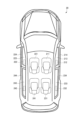
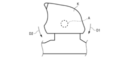
- 2 illustrates a vehicle in which the device of FIG. 1 is mounted; 3 illustrates an example of a configuration of a switch mounted on the vehicle of FIG. 2 .
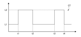
- 2 illustrates a first output mode of the control signal in FIG. 1;
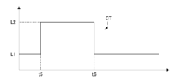
- 2 illustrates a second output mode of the control signal in FIG. 1;
- 3 illustrates an example of a passenger compartment of the vehicle of FIG. 2;
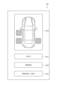
- 7 illustrates an example of a setting image displayed on the display device of FIG. 6.
- FIG. 1 illustrates an example of the functional configuration of a control device 10 according to one embodiment.
- the control device 10 is mounted at an appropriate position in a vehicle 20 illustrated in FIG. 2.
- the control device 10 includes an input interface 11.
- the input interface 11 is configured as a hardware interface that receives a first signal S1 output from a first switch 31 and a second signal S2 output from a second switch 32.
- the first switch 31 and the second switch 32 are mounted on the vehicle 20.
- the first signal S1 is generated based on a first operation performed on the first switch 31.
- the first signal S1 may be a digital signal or an analog signal depending on the specifications of the first switch 31. If the first signal S1 is an analog signal, the input interface 11 is provided with an appropriate conversion circuit including an A/D converter.
- the second signal S2 is generated based on an operation performed on the second switch 32.
- the second signal S2 may be a digital signal or an analog signal depending on the specifications of the second switch 32. If the second signal S2 is an analog signal, the input interface 11 is provided with an appropriate conversion circuit including an A/D converter.
- the control device 10 includes a processor 12 and an output interface 13.
- the processor 12 is configured to output a control signal CT in a first manner from the output interface 13 to the first opening/closing device 411 mounted on the vehicle 20 when the input interface 11 receives a first signal S1.
- the processor 12 is configured to output a control signal CT in a first manner from the output interface 13 to the second opening/closing device 412 mounted on the vehicle 20 when the input interface 11 receives a second signal S2.
- the control signal CT output in the first mode is configured to cause the first opening/closing device 411 and the second opening/closing device 412 to open and close the first opening/closing body 421 and the second opening/closing body 422 mounted on the vehicle 20, respectively, in a first manner.
- the output interface 13 is configured as a hardware interface.
- the control signal CT may be a digital signal or an analog signal. If the control signal CT is an analog signal, the output interface 13 is equipped with an appropriate conversion circuit including a D/A converter.
- the input interface 11 is also configured as a hardware interface that accepts the third signal S3 output from the first switch 31.
- the third signal S3 is generated based on the second operation performed on the first switch 31.
- the third signal S3 may be a digital signal or an analog signal depending on the specifications of the first switch 31. If the third signal S3 is an analog signal, the input interface 11 is provided with an appropriate conversion circuit including an A/D converter.
- the processor 12 is configured to output a control signal CT in a second manner from the output interface 13 to the first opening/closing device 411 and the second opening/closing device 412 when the input interface 11 receives the third signal S3.
- the first and second manners are different.
- the control signal CT output in the second manner is configured to cause the first opening/closing device 411 and the second opening/closing device 412 to open and close the first opening/closing body 421 and the second opening/closing body 422, respectively, in a second manner.
- the first and second methods are different.
- the processor 12 when the input interface 11 receives the third signal S3, the processor 12 is configured to change the manner in which the first opening/closing device 411 and the second opening/closing device 412 operate the first opening/closing body 421 and the second opening/closing body 422 by changing the state of the control signal CT output from the output interface 13.
- the vehicle 20 has a plurality of seats.
- the plurality of seats includes a right front seat 211, a left front seat 221, a right rear seat 231, and a left rear seat 241.
- the right front seat 211 is installed in the right front part of the vehicle 20.
- the expression “right part of the vehicle 20” means a part of the vehicle 20 located to the right of the center in the left-right direction of the vehicle 20.
- the expression “front part of the vehicle 20” means a part of the vehicle 20 located forward of the center in the fore-aft direction of the vehicle 20.
- the expression “right front part of the vehicle 20” means a part that is both the right part and the front part of the vehicle 20.
- the left front seat 221 is installed in the left front part of the vehicle 20.
- the expression “left part of the vehicle 20” means a part of the vehicle 20 located to the left of the center in the left-right direction of the vehicle 20.
- the expression “left front part of the vehicle 20” means a part that is both the left part and the front part of the vehicle 20.
- an element is described as being “installed in the left front part of the vehicle 20,” it means that at least a part (preferably the majority of a part) of the element is installed in the left front part of the vehicle 20.
- the right rear seat 231 is installed in the right rear of the vehicle 20.
- the expression “rear of the vehicle 20” means a part of the vehicle 20 located rearward of the center in the fore-and-aft direction of the vehicle 20.
- the expression “right rear of the vehicle 20” means a part that is both the right and rear of the vehicle 20.
- the left rear seat 241 is located in the left rear of the vehicle 20.
- the expression “left rear of the vehicle 20” means the part of the vehicle 20 that is both the left and rear.
- the vehicle 20 is equipped with a right front switch 212 and a right front window 213.
- the right front switch 212 and the right front window 213 are installed on the right front part of the vehicle 20.
- the right front switch 212 is configured to be operated to open and close the right front window 213.
- the right front window 213 is opened and closed by an opening and closing device (not shown) installed on the right front part of the vehicle 20.
- the vehicle 20 is equipped with a left front switch 222 and a left front window 223.
- the left front switch 222 and the left front window 223 are installed on the left front part of the vehicle 20.
- the left front switch 222 is configured to be operated to open and close the left front window 223.
- the left front window 223 is opened and closed by an opening and closing device (not shown) installed on the left front part of the vehicle 20.
- the vehicle 20 is equipped with a right rear switch 232 and a right rear window 233.
- the right rear switch 232 and the right rear window 233 are installed at the right rear of the vehicle 20.
- the right rear switch 232 is configured to be operated to open and close the right rear window 233.
- the right rear window 233 is opened and closed by an opening and closing device (not shown) installed at the right rear of the vehicle 20.
- the vehicle 20 is equipped with a left rear switch 242 and a left rear window 243.
- the left rear switch 242 and the left rear window 243 are installed on the left rear of the vehicle 20.
- the left rear switch 242 is configured to be operated to open and close the left rear window 243.
- the left rear window 243 is opened and closed by an opening and closing device (not shown) installed on the left rear of the vehicle 20.
- Each of the right front switch 212, the left front switch 222, the right rear switch 232, and the left rear switch 242 is equipped with a knob K, as illustrated in FIG. 3.
- the knob K is configured to be operable by the occupant's fingers.
- the knob K is configured to be rotatable in the clockwise direction and counterclockwise direction in FIG. 3 about an axis A.
- the clockwise direction in FIG. 3 is referred to as the first direction D1
- the counterclockwise direction in FIG. 3 is referred to as the second direction D2.
- the knob K of the switch associated with that window is rotated in a first direction D1.
- the knob K of the switch associated with that window is rotated in a second direction D2.
- the knob K is configured to return to a neutral position when the occupant releases his or her finger from the knob K.
- the right front switch 212 can function as the first switch 31 described with reference to FIG. 1. Therefore, the right front window 213 can be an example of a first opening/closing body 421.
- the right front seat 211 can be an example of a first seat.
- the right front switch 212 is configured to output a first signal S1 indicating that the knob K is being rotated in the first direction D1 while the knob K is being rotated in the first direction D1 by the occupant. Therefore, while the occupant is rotating the knob K of the right front switch 212 in the first direction D1, the control device 10 outputs a control signal CT to cause the opening and closing device to open the right front window 213.
- the right front switch 212 is configured to output a first signal S1 indicating that the knob K is being rotated in the second direction D2 while the knob K is being rotated in the second direction D2 by the occupant. Therefore, while the occupant is rotating the knob K of the right front switch 212 in the second direction D2, the control device 10 outputs a control signal CT to cause the opening and closing device to close the right front window 213.
- Each of the left front switch 222, the right rear switch 232, and the left rear switch 242 can function as the second switch 32 described with reference to FIG. 1. Therefore, the left front window 223, the right rear window 233, and the left rear window 243 can be an example of the second opening/closing body 422.
- the left front seat 221, the right rear seat 231, and the left rear seat 241 can be an example of the second seat.
- each of the left front switch 222, the right rear switch 232, and the left rear switch 242 is configured to output a second signal S2 indicating that the knob K is being rotated in the first direction D1 while the knob K is being rotated in the first direction D1 by the occupant. Therefore, while the occupant is rotating the knob K of a particular switch in the first direction D1, the control device 10 outputs a control signal CT to cause the opening and closing device to open the window associated with that switch.
- each of the left front switch 222, the right rear switch 232, and the left rear switch 242 is configured to output a second signal S2 indicating that the knob K is being rotated in the second direction D2 while the knob K is being rotated in the second direction D2 by the occupant. Therefore, while the occupant is rotating the knob K of a particular switch in the second direction D2, the control device 10 outputs a control signal CT to cause the opening and closing device to close the window associated with that switch.
- a method of opening and closing a window associated with a particular switch while an occupant is turning the knob K of that switch is an example of the first method.
- the output mode of the control signal CT for achieving this opening and closing operation is an example of the first mode.
- the switch operated by the driver of the vehicle 20 is generally configured to be capable of performing an automatic opening and closing operation of the corresponding window.
- the term "automatic window opening and closing operation" as used in this specification means an operation that automatically brings the window to a fully open or fully closed state in response to an operation input. To perform the automatic opening and closing operation, an operation different from the operation described above must be performed on the knob K.
- the right front switch 212 is configured to be capable of performing an automatic opening and closing operation of the right front window 213.
- the right front switch 212 in this embodiment is also configured to be able to accept an operation to execute an automatic opening and closing operation for all windows at once. In this case, it is necessary to perform an operation on the knob K that is different from the operation for performing the normal opening and closing operation described with reference to FIG. 3 and the operation for executing the automatic opening and closing operation for only the right front window 213 described above.
- an occupant who wishes to automatically open all the windows can perform an operation to rotate the knob K intermittently multiple times in the first direction D1.
- An occupant who wishes to automatically close all the windows can perform an operation to rotate the knob K intermittently multiple times in the second direction D2.
- the operation of the right front switch 212 to perform the automatic opening and closing operation for all the windows is an example of the second operation.
- the right front switch 212 which has received an operation to execute an automatic opening/closing operation for all windows, is configured to output a third signal S3. Therefore, the control device 10 outputs a control signal CT that executes an automatic opening/closing operation for all windows in response to the operation.
- the method of bringing all windows into a fully open or fully closed state in response to the second operation of the right front switch 212 is an example of the second method.
- the output mode of the control signal CT to realize this opening/closing operation is an example of the second mode.
- FIG. 4 illustrates an example of the control signal CT output from the control device 10 when the left rear window 243 is opened through the operation of the left rear switch 242.
- the horizontal axis represents time.
- the vertical axis represents signal level.
- Signal level L1 corresponds to a state in which the opening and closing device is stopped.
- Signal level L2 corresponds to a state in which the opening and closing device is operating.
- FIG. 5 illustrates an example of the control signal CT output from the control device 10 when the automatic opening operation of the left rear window 243 is performed through the second operation of the right front switch 212.
- a control signal CT of signal level L2 is output from the control device 10, and the opening/closing device 41 executes an operation to open the left rear window 243.
- the output of the control signal CT continues until the left rear window 243 reaches the fully open state at time t6.
- the function can be realized without changing the physical configuration of the existing right front switch 212 that does not have the function, or without providing a new control signal transmission path.
- the third signal S3 that triggers the execution of the function is generated by the existing right front switch 212, there is no need to secure a permanently occupied physical space to generate the third signal S3. Therefore, it is possible to diversify the controllable functions while suppressing an increase in the space physically occupied by the switch.
- the opening and closing operation that is enabled for all windows by the second operation of the right front switch 212 is not limited to the automatic opening and closing operation. Examples of other opening and closing operations include stopping the opening and closing operation at a specific preset position, prohibiting the opening operation, etc.
- the vehicle 20 is equipped with a display device 25.
- the display device 25 is configured to be capable of displaying a setting image 251 illustrated in FIG. 7.
- the display device 25 may be a general-purpose display device capable of displaying a variety of images. Therefore, the setting image 251 does not need to be displayed at all times or permanently.
- the display device 25 is configured as an electrostatic or pressure-sensitive touch panel display. In other words, the user can input operations by bringing a part of the body, such as a finger, close to or into contact with the setting image 251 displayed on the display device 25.
- the display device 25 is disposed in front of the right front seat 211. Therefore, the setting image 251 is operated by a passenger seated in the right front seat 211.
- the display device 25 may be installed in a center cluster located in the center of the front part of the vehicle 20. In this case, the setting image 251 can be operated by either a passenger seated in the right front seat 211 or a passenger seated in the left front seat 221.
- the setting image 251 has a configuration for changing the association between the second operation of the right front switch 212 and the opening and closing operations that are enabled for all windows by that operation.
- the setting image 251 includes a first icon image 2511, a second icon image 2512, and a third icon image 2513.
- the first icon image 2511 is configured to be operated to enable automatic opening and closing operations for all windows.
- the second icon image 2512 is configured to be operated to stop opening and closing operations at a specific position that is set in advance for all windows.
- the third icon image 2513 is configured to be operated to prohibit opening operations for all windows.
- FIG. 1 it is also configured as a hardware interface that accepts a fourth signal S4 output from the display device 25.
- the fourth signal S4 is generated based on an operation input to the setting image 251 displayed on the display device 25.
- the fourth signal S4 is configured to include information representing the opening/closing operation set based on the operation input.
- the fourth signal S4 may be a digital signal or an analog signal depending on the specifications of the display device 25. If the fourth signal S4 is an analog signal, the input interface 11 is provided with an appropriate conversion circuit including an A/D converter.
- the processor 12 stores the information representing the set operation in a storage device (not shown) in a referenceable state.
- the storage device can be realized by a semiconductor memory, a hard disk device, or the like.
- the processor 12 can refer to the information stored in the storage in response to a user request made as necessary, and output from the output interface 13 a display control signal (not shown) that causes the display device 25 to display the currently enabled opening and closing operation.
- the display control signal may be a digital signal or an analog signal depending on the specifications of the display device 25. If the display control signal is an analog signal, the output interface 13 is provided with an appropriate conversion circuit including a D/A converter.
- the opening/closing action assigned to the second operation of the right front switch 212 is changed based on the operation input to the setting image 251 displayed on the display device 25, making it easier to understand the functions that are enabled and reducing the need to remember the enabled functions.
- the processor 12 of the control device 10 having the various functions described above can be realized by a dedicated integrated circuit such as a microcontroller, ASIC, or FPGA that has a memory element in which a computer program for implementing the function is pre-installed.
- the memory element is an example of a non-transitory computer-readable medium that stores a computer program.
- the processor 12 may be realized by a general-purpose microprocessor that operates in cooperation with a general-purpose memory.
- the general-purpose microprocessor include a CPU, an MPU, and a GPU.
- the general-purpose memory include a ROM and a RAM.
- a computer program for realizing the function may be stored in the ROM.
- the general-purpose microprocessor specifies at least a part of the computer program stored in the ROM, deploys it on the RAM, and executes the above-mentioned process in cooperation with the RAM.
- the general-purpose memory is an example of a non-transitory computer-readable medium that stores a computer program.
- the computer program may be pre-installed in the general-purpose memory, or may be downloaded from an external server device via a wireless communication network to which the control device 10 can be connected, and then installed in the general-purpose memory.
- the external server device is an example of a non-transitory computer-readable medium that stores a computer program.
- Processor 12 may be implemented as a combination of a general-purpose microprocessor and a dedicated integrated circuit.
- the function assigned to the second operation of the right front switch 212 is enabled for all windows other than the right front window 213.
- the function can be enabled for at least one window other than the right front window 213.
- the setting image 251 may include a selection user interface 2514.
- the selection user interface 2514 includes selection icons corresponding to the left front window 223, the right rear window 233, and the left rear window 243. The user can select the window for which he or she wishes to activate the function assigned to the second operation of the right front switch 212 by operating the selection icon.
- the opening and closing bodies that are opened and closed based on the control signal CT output from the control device 10 are not limited to the windows of the vehicle 20.
- the opening and closing control of the right front door 214, the left front door 224, the right rear door 234, and the left rear door 244 can also be performed by the control device 10.
- the displacement of the doors may be by a hinge system or a sliding system.
- the control device 10 may also be installed in a moving object other than a vehicle 20.
- moving objects include trains, airplanes, ships, etc.
- the moving object may not require a driver.
- the control device 10 does not need to be mounted on a mobile object.
- the control device 10 can be used to open and close appropriate opening and closing objects installed in homes and facilities. Examples of such opening and closing objects include gates, doors, windows, shutters, blinds, curtains, screens, etc.
Landscapes
- Engineering & Computer Science (AREA)
- Mechanical Engineering (AREA)
- General Engineering & Computer Science (AREA)
- Theoretical Computer Science (AREA)
- Human Computer Interaction (AREA)
- Physics & Mathematics (AREA)
- General Physics & Mathematics (AREA)
- Power-Operated Mechanisms For Wings (AREA)
Abstract
入力インタフェース(11)は、第一スイッチ(31)の第一操作に基づいて生成される第一信号(S1)、および第二スイッチ(32)の操作に基づいて生成される第二信号(S2)を受け付ける。プロセッサ(12)は、入力インタフェース(11)が第一信号(S1)を受け付けると、制御信号(CT)を第一の態様で出力することにより第一開閉体(421)を第一の方法で開閉させ、入力インタフェース(11)が第二信号(S2)を受け付けると、制御信号(CT)を第一の態様で出力することにより第二開閉体(422)を第一の方法で開閉させる。プロセッサ(12)は、第一操作と異なる第一スイッチ(31)の第二操作に基づいて生成される第三信号(S3)を入力インタフェース(11)が受け付けると、制御信号(CT)を第一の態様と異なる第二の態様で出力することにより、第一開閉体(421)と第二開閉体(422)を第一の方法と異なる第二の方法で開閉させる。
Description
本開示は、スイッチに入力される操作に基づいて開閉体の動作制御を行なう制御装置に関連する。本開示は、当該制御装置に搭載されたプロセッサにより実行可能なコンピュータプログラムを記憶した非一時的なコンピュータ可読媒体にも関連する。
日本国特許出願公開2013-004465号公報は、車両の運転席に搭載されるスイッチ装置を開示している。当該スイッチ装置は、複数のノブを備えている。複数のノブの各々は、車両に搭載された複数の窓の一つに対応付けられている。運転者が特定の窓の開閉を希望する場合、当該窓に対応付けられた複数のノブの一つを操作する。スイッチ装置は、ノブの操作に応じた制御信号を出力する。ウインドウレギュレータは、当該制御信号に基づいて窓を開閉する。
スイッチにより物理的に占有される空間の増加を抑制しつつ、制御可能な機能の多様化を図ることが求められている。
本開示により提供される一態様例は、制御装置であって、
第一スイッチの第一操作に基づいて生成される第一信号、および第二スイッチの操作に基づいて生成される第二信号を受け付けるインタフェースと、
前記インタフェースが前記第一信号を受け付けると、制御信号を第一の態様で出力することにより第一開閉体を第一の方法で開閉させ、前記インタフェースが前記第二信号を受け付けると、当該制御信号を第一の態様で出力することにより第二開閉体を前記第一の方法で開閉させるプロセッサと、
を備えており、
前記プロセッサは、前記第一操作と異なる前記第一スイッチの第二操作に基づいて生成される第三信号を前記インタフェースが受け付けると、前記制御信号を前記第一の態様と異なる第二の態様で出力することにより、前記第一開閉体と前記第二開閉体を前記第一の方法と異なる第二の方法で開閉させる。
第一スイッチの第一操作に基づいて生成される第一信号、および第二スイッチの操作に基づいて生成される第二信号を受け付けるインタフェースと、
前記インタフェースが前記第一信号を受け付けると、制御信号を第一の態様で出力することにより第一開閉体を第一の方法で開閉させ、前記インタフェースが前記第二信号を受け付けると、当該制御信号を第一の態様で出力することにより第二開閉体を前記第一の方法で開閉させるプロセッサと、
を備えており、
前記プロセッサは、前記第一操作と異なる前記第一スイッチの第二操作に基づいて生成される第三信号を前記インタフェースが受け付けると、前記制御信号を前記第一の態様と異なる第二の態様で出力することにより、前記第一開閉体と前記第二開閉体を前記第一の方法と異なる第二の方法で開閉させる。
本開示により提供される一態様例は、制御装置に搭載されたプロセッサにより実行可能なコンピュータプログラムを記憶した非一時的なコンピュータ可読媒体であって、
実行されることにより、前記制御装置は、
第一スイッチの第一操作に基づいて生成される第一信号を受け付けると、制御信号を第一の態様で出力することにより第一開閉体を第一の方法で開閉させ、
第二スイッチの操作に基づいて生成される第二信号を受け付けると、前記制御信号を第一の態様で出力することにより第二開閉体を前記第一の方法で開閉させ、
前記第一操作と異なる前記第一スイッチの第二操作に基づいて生成される第三信号を受け付けると、前記制御信号を前記第一の態様と異なる第二の態様で出力することにより、前記第一開閉体と前記第二開閉体を前記第一の方法と異なる第二の方法で開閉させる。
実行されることにより、前記制御装置は、
第一スイッチの第一操作に基づいて生成される第一信号を受け付けると、制御信号を第一の態様で出力することにより第一開閉体を第一の方法で開閉させ、
第二スイッチの操作に基づいて生成される第二信号を受け付けると、前記制御信号を第一の態様で出力することにより第二開閉体を前記第一の方法で開閉させ、
前記第一操作と異なる前記第一スイッチの第二操作に基づいて生成される第三信号を受け付けると、前記制御信号を前記第一の態様と異なる第二の態様で出力することにより、前記第一開閉体と前記第二開閉体を前記第一の方法と異なる第二の方法で開閉させる。
上記の各態様例に係る構成においては、制御装置から第一開閉装置と第二開閉装置へ出力される制御信号の出力態様を変更することによって、第一スイッチへの操作入力に基づいて第二の方法に係る開閉動作を第一開閉体と第二開閉体に実行させるという新たな機能を発現させている。すなわち、当該機能を有していない既存の第一スイッチの物理的な構成を変更したり、新たな制御信号の伝達経路を設けたりすることなく、当該機能を発現させることができる。加えて、当該機能実行のトリガとなる第三信号は、既存の第一スイッチにより生成されるので、永続的に占有される物理的スペースを、第三信号を生成するために確保する必要がない。したがって、スイッチにより物理的に占有される空間の増加を抑制しつつ、制御可能な機能の多様化を図ることができる。
添付の図面を参照しつつ、実施形態例について以下詳細に説明する。以下の説明に用いられる各図面においては、各要素を認識可能な大きさとするために縮尺が適宜変更されている。
図1は、一実施形態に係る制御装置10の機能構成を例示している。制御装置10は、図2に例示される車両20における適宜の位置に搭載される。
図1に例示されるように、制御装置10は、入力インタフェース11を備えている。入力インタフェース11は、第一スイッチ31から出力される第一信号S1と第二スイッチ32から出力される第二信号S2を受け付けるハードウェアインタフェースとして構成されている。第一スイッチ31と第二スイッチ32は、車両20に搭載されている。
第一信号S1は、第一スイッチ31に対してなされる第一操作に基づいて生成される。第一信号S1は、第一スイッチ31の仕様に応じてデジタル信号であってもよいし、アナログ信号であってもよい。第一信号S1がアナログ信号である場合、入力インタフェース11は、A/Dコンバータを含む適宜の変換回路を備える。
第二信号S2は、第二スイッチ32に対してなされる操作に基づいて生成される。第二信号S2は、第二スイッチ32の仕様に応じてデジタル信号であってもよいし、アナログ信号であってもよい。第二信号S2がアナログ信号である場合、入力インタフェース11は、A/Dコンバータを含む適宜の変換回路を備える。
制御装置10は、プロセッサ12と出力インタフェース13を備えている。プロセッサ12は、入力インタフェース11が第一信号S1を受け付けると、出力インタフェース13から車両20に搭載された第一開閉装置411へ第一の態様で制御信号CTを出力するように構成されている。同様に、プロセッサ12は、入力インタフェース11が第二信号S2を受け付けると、出力インタフェース13から車両20に搭載された第二開閉装置412へ第一の態様で制御信号CTを出力するように構成されている。
第一の態様で出力される制御信号CTは、第一開閉装置411と第二開閉装置412にそれぞれ車両20に搭載された第一開閉体421と第二開閉体422を第一の方法で開閉させるように構成されている。
出力インタフェース13は、ハードウェアインタフェースとして構成されている。制御信号CTは、デジタル信号であってもよいし、アナログ信号であってもよい。制御信号CTがアナログ信号である場合、出力インタフェース13は、D/Aコンバータを含む適宜の変換回路を備える。
入力インタフェース11は、第一スイッチ31から出力される第三信号S3を受け付けるハードウェアインタフェースとしても構成されている。
第三信号S3は、第一スイッチ31に対してなされる第二操作に基づいて生成される。第三信号S3は、第一スイッチ31の仕様に応じてデジタル信号であってもよいし、アナログ信号であってもよい。第三信号S3がアナログ信号である場合、入力インタフェース11は、A/Dコンバータを含む適宜の変換回路を備える。
プロセッサ12は、入力インタフェース11が第三信号S3を受け付けると、出力インタフェース13から第一開閉装置411と第二開閉装置412へ第二の態様で制御信号CTを出力するように構成されている。第一態様と第二態様は相違している。第二の態様で出力される制御信号CTは、第一開閉装置411と第二開閉装置412にそれぞれ第一開閉体421と第二開閉体422を第二の方法で開閉させるように構成されている。第一の方法と第二の方法は相違している。
換言すると、プロセッサ12は、入力インタフェース11が第三信号S3を受け付けると、出力インタフェース13から出力される制御信号CTの態様を変化させることにより、第一開閉装置411と第二開閉装置412による第一開閉体421と第二開閉体422の動作のさせ方を変更するように構成されている。
車両20は、複数の座席を備えている。複数の座席は、右前座席211、左前座席221、右後座席231、および左後座席241を含んでいる。
右前座席211は、車両20の右前部に設置されている。本明細書においては、「車両20の右部」という表現は、車両20の左右方向における中央よりも右方に位置する車両20の一部を意味する。「車両20の前部」という表現は、車両20の前後方向における中央よりも前方に位置する車両20の一部を意味する。「車両20の右前部」という表現は、車両20の右部でありかつ前部である部分を意味する。ある要素が「車両20の右前部に設置されている」と記載される場合、当該要素の少なくとも一部(好ましくは大半の部分)が車両20の右前部に設置されていることを意味する。
左前座席221は、車両20の左前部に設置されている。本明細書においては、「車両20の左部」という表現は、車両20の左右方向における中央よりも左方に位置する車両20の一部を意味する。「車両20の左前部」という表現は、車両20の左部でありかつ前部である部分を意味する。ある要素が「車両20の左前部に設置されている」と記載される場合、当該要素の少なくとも一部(好ましくは大半の部分)が車両20の左前部に設置されていることを意味する。
右後座席231は、車両20の右後部に設置されている。本明細書においては、「車両20の後部」という表現は、車両20の前後方向における中央よりも後方に位置する車両20の一部を意味する。「車両20の右後部」という表現は、車両20の右部でありかつ後部である部分を意味する。ある要素が「車両20の右後部に設置されている」と記載される場合、当該要素の少なくとも一部(好ましくは大半の部分)が車両20の右後部に設置されていることを意味する。
左後座席241は、車両20の左後部に設置されている。本明細書においては、「車両20の左後部」という表現は、車両20の左部でありかつ後部である部分を意味する。ある要素が「車両20の左後部に設置されている」と記載される場合、当該要素の少なくとも一部(好ましくは大半の部分)が車両20の左後部に設置されていることを意味する。
車両20は、右前スイッチ212と右前窓213を備えている。右前スイッチ212と右前窓213は、車両20の右前部に設置されている。右前スイッチ212は、右前窓213を開閉するために操作されるように構成されている。右前窓213の開閉は、車両20の右前部に設置された不図示の開閉装置によりなされる。
車両20は、左前スイッチ222と左前窓223を備えている。左前スイッチ222と左前窓223は、車両20の左前部に設置されている。左前スイッチ222は、左前窓223を開閉するために操作されるように構成されている。左前窓223の開閉は、車両20の左前部に設置された不図示の開閉装置によりなされる。
車両20は、右後スイッチ232と右後窓233を備えている。右後スイッチ232と右後窓233は、車両20の右後部に設置されている。右後スイッチ232は、右後窓233を開閉するために操作されるように構成されている。右後窓233の開閉は、車両20の右後部に設置された不図示の開閉装置によりなされる。
車両20は、左後スイッチ242と左後窓243を備えている。左後スイッチ242と左後窓243は、車両20の左後部に設置されている。左後スイッチ242は、左後窓243を開閉するために操作されるように構成されている。左後窓243の開閉は、車両20の左後部に設置された不図示の開閉装置によりなされる。
右前スイッチ212、左前スイッチ222、右後スイッチ232、および左後スイッチ242の各々は、図3に例示されるように、ノブKを備えている。ノブKは、乗員の手指により操作可能に構成されている。具体的には、ノブKは、軸Aを中心として図3における時計回り方向と反時計回り方向へ回動可能に構成されている。以降の説明においては、図3における時計回り方向を第一方向D1と称し、図3における反時計回り方向を第二方向D2と称する。
乗員が特定の窓を開けることを希望する場合、当該窓に対応付けられたスイッチのノブKが第一方向D1へ回動される。乗員が特定の窓を閉じることを希望する場合、当該窓に対応付けられたスイッチのノブKが第二方向D2へ回動される。ノブKは、乗員がノブKから指を離すと中立位置に戻るように構成されている。
右前スイッチ212は、図1を参照して説明した第一スイッチ31として機能しうる。したがって、右前窓213は、第一開閉体421の一例となりうる。右前座席211は、第一の座席の一例となりうる。
具体的には、右前スイッチ212は、ノブKが乗員により第一方向D1に回動されている間、ノブKが第一方向D1に回動されていることを表す第一信号S1を出力するように構成されている。したがって、制御装置10は、乗員が右前スイッチ212のノブKを第一方向D1に回動させている間、右前窓213を開閉装置に開かせる制御信号CTを出力する。
同様に、右前スイッチ212は、ノブKが乗員により第二方向D2に回動されている間、ノブKが第二方向D2に回動されていることを表す第一信号S1を出力するように構成されている。したがって、制御装置10は、乗員が右前スイッチ212のノブKを第二方向D2に回動させている間、右前窓213を開閉装置に閉じさせる制御信号CTを出力する。
左前スイッチ222、右後スイッチ232、および左後スイッチ242の各々は、図1を参照して説明した第二スイッチ32として機能しうる。したがって、左前窓223、右後窓233、および左後窓243は、第二開閉体422の一例となりうる。左前座席221、右後座席231、および左後座席241は、第二座席の一例となりうる。
具体的には、左前スイッチ222、右後スイッチ232、および左後スイッチ242の各々は、ノブKが乗員により第一方向D1に回動されている間、ノブKが第一方向D1に回動されていることを表す第二信号S2を出力するように構成されている。したがって、制御装置10は、乗員が特定のスイッチのノブKを第一方向D1に回動させている間、当該スイッチに対応付けられた窓を開閉装置に開かせる制御信号CTを出力する。
同様に、左前スイッチ222、右後スイッチ232、および左後スイッチ242の各々は、ノブKが乗員により第二方向D2に回動されている間、ノブKが第二方向D2に回動されていることを表す第二信号S2を出力するように構成されている。したがって、制御装置10は、乗員が特定のスイッチのノブKを第二方向D2に回動させている間、当該スイッチに対応付けられた窓を開閉装置に閉じさせる制御信号CTを出力する。
すなわち、乗員が特定のスイッチのノブKを回動させている間に当該スイッチに対応付けられた窓を開閉させる方法は、第一の方法の一例である。この開閉動作を実現するための制御信号CTの出力態様は、第一の態様の一例である。
車両20の運転者により操作されるスイッチは、対応する窓のオート開閉動作を実行できるように構成されることが一般的である。本明細書で用いられる「窓のオート開閉動作」という語は、操作入力に応答して窓を自動的に全開状態または全閉状態に至らせる動作を意味する。オート開閉動作を実行するためには、前述した操作とは異なる操作をノブKに対して行なう必要がある。本例においては、右前スイッチ212が右前窓213のオート開閉動作を実行できるように構成されている。
本実施形態に係る右前スイッチ212は、全ての窓について一斉にオート開閉動作を実行する操作も受け付け可能に構成されている。この場合、図3を参照して説明した通常の開閉動作を行なうための操作、および上述した右前窓213のみについてオート開閉動作を実行するための操作と異なる操作を、ノブKに対して行なう必要がある。
例えば、全ての窓を自動的に全開状態にする動作を希望する乗員は、ノブKを第一方向D1へ複数回断続的に回動させる操作を行ないうる。全ての窓を自動的に全閉状態にする動作を希望する乗員は、ノブKを第二方向D2へ複数回断続的に回動させる操作を行ないうる。全ての窓についてオート開閉動作を実行するための右前スイッチ212の操作は、第二操作の一例である。
全ての窓についてオート開閉動作を実行するための操作を受け付けた右前スイッチ212は、第三信号S3を出力するように構成されている。したがって、制御装置10は、当該操作に応じて、全ての窓についてオート開閉動作を実行させる制御信号CTを出力する。すなわち、右前スイッチ212の第二操作に応じて全ての窓を全開または全閉状態にする方法は、第二の方法の一例である。この開閉動作を実現するための制御信号CTの出力態様は、第二の態様の一例である。
図4は、左後スイッチ242の操作を通じて左後窓243を開く場合に制御装置10から出力される制御信号CTの態様を例示している。横軸は時間を表している。縦軸は信号レベルを表している。信号レベルL1は、開閉装置が停止している状態に対応している。信号レベルL2は、開閉装置が作動している状態に対応している。
時点t1において左後スイッチ242のノブKが乗員の指により第一方向D1に回動されると、信号レベルL2の制御信号CTが制御装置10から出力され、開閉装置により左後窓243を開く動作が実行される。
時点t2において乗員の指が左後スイッチ242のノブKから離れると、制御信号CTの出力が停止(信号レベルL1に低下)し、左後窓243が開かれる動作が中断される。
時点t3において左後スイッチ242のノブKが乗員の指により再び第一方向D1に回動されると、信号レベルL2の制御信号CTが制御装置10から出力され、開閉装置により左後窓243を開く動作が再開される。時点t4において左後窓243が全開状態に達すると、制御信号CTの出力が自動的に停止される。
図5は、右前スイッチ212の第二操作を通じて左後窓243のオート開動作が実行される場合に制御装置10から出力される制御信号CTの態様を例示している。
時点t5においてオート開動作を実行するための操作が右前スイッチ212に入力されると、信号レベルL2の制御信号CTが制御装置10から出力され、開閉装置41により左後窓243を開く動作が実行される。制御信号CTの出力は、時点t6において左後窓243が全開状態に達するまで継続される。
上記のような構成においては、制御装置10から第一開閉装置411と第二開閉装置412へ出力される制御信号CTの出力態様を変更することによって、右前スイッチ212への操作入力に基づいて全ての窓のオート開閉動作を実行させるという新たな機能を発現させている。すなわち、当該機能を有していない既存の右前スイッチ212の物理的な構成を変更したり、新たな制御信号の伝達経路を設けたりすることなく、当該機能を発現させることができる。加えて、当該機能実行のトリガとなる第三信号S3は、既存の右前スイッチ212により生成されるので、永続的に占有される物理的スペースを、第三信号S3を生成するために確保する必要がない。したがって、スイッチにより物理的に占有される空間の増加を抑制しつつ、制御可能な機能の多様化を図ることができる。
なお、右前スイッチ212の第二操作により全ての窓について有効とされる開閉動作は、オート開閉動作に限られない。別の開閉動作の例としては、予め設定された特定の位置での開閉動作の停止、開動作の禁止などが挙げられる。
図6に例示されるように、車両20は、表示装置25を備えている。表示装置25は、図7に例示される設定用画像251を表示可能に構成されている。表示装置25は、様々な画像を表示しうる汎用の表示装置でありうる。したがって、設定用画像251は常時あるいは永続的に表示されていることを要しない。表示装置25は、静電型あるいは感圧型のタッチパネルディスプレイとして構成されている。すなわち、ユーザは、表示装置25に表示された設定用画像251に手指などの身体の一部を接近または接触させることにより、操作を入力できる。
本例においては、表示装置25は、右前座席211の前方に配置されている。したがって、設定用画像251は、右前座席211に着座した乗員により操作される。しかしながら、表示装置25は、車両20の前部中央に位置するセンタクラスタに設置されてもよい。この場合、設定用画像251は、右前座席211に着座した乗員と左前座席221に着座した乗員のいずれかにより操作されうる。
設定用画像251は、右前スイッチ212の第二操作と、当該操作により全ての窓について有効にされる開閉動作の関連付けを変更するための構成を有している。
本例においては、設定用画像251は、第一アイコン画像2511、第二アイコン画像2512、および第三アイコン画像2513を含んでいる。第一アイコン画像2511は、全ての窓についてオート開閉動作を有効にするために操作されるように構成されている。第二アイコン画像2512は、全ての窓について予め設定された特定の位置で開閉動作を停止させるために操作されるように構成されている。第三アイコン画像2513は、全ての窓について開動作を禁止するために操作されるように構成されている。
図1に例示されるように、表示装置25から出力される第四信号S4を受け付けるハードウェアインタフェースとしても構成されている。
第四信号S4は、表示装置25に表示された設定用画像251に対する操作入力に基づいて生成される。第四信号S4は、当該操作入力に基づいて設定された開閉動作を表す情報を含むように構成される。第四信号S4は、表示装置25の仕様に応じてデジタル信号であってもよいし、アナログ信号であってもよい。第四信号S4がアナログ信号である場合、入力インタフェース11は、A/Dコンバータを含む適宜の変換回路を備える。
プロセッサ12は、入力インタフェース11が第四信号S4を受け付けると、設定された動作を表す情報を、参照可能な状態で不図示のストレージに格納する。ストレージは、半導体メモリやハードディスク装置などにより実現されうる。
プロセッサ12は、必要に応じてなされるユーザからの要求に応じてストレージに格納された情報を参照し、現在有効にされている開閉動作を表示装置25に表示させる表示制御信号(不図示)を出力インタフェース13から出力させうる。表示制御信号は、表示装置25の仕様に応じてデジタル信号であってもよいし、アナログ信号であってもよい。表示制御信号がアナログ信号である場合、出力インタフェース13は、D/Aコンバータを含む適宜の変換回路を備える。
上記のように右前スイッチ212の第二操作に割り当てられる開閉動作を変更可能とすることにより、スイッチにより物理的に占有される空間の増加を抑制しつつ、制御可能な機能の多様化を図ることができるという有利な効果をより顕著にできる。
特に本実施形態においては、右前スイッチ212の第二操作に割り当てられる開閉動作の変更が、表示装置25に表示された設定用画像251に対する操作入力に基づいてなされるので、有効にされる機能の把握を容易化できるとともに、有効にされた機能を記憶に留めておく必要性を低減できる。
これまで説明した各種の機能を有する制御装置10のプロセッサ12は、当該機能を実現するためのコンピュータプログラムがプリインストールされた記憶素子を備えたマイクロコントローラ、ASIC、FPGAなどの専用集積回路によって実現されうる。この場合、当該記憶素子は、コンピュータプログラムを記憶した非一時的なコンピュータ可読媒体の一例である。
あるいは、プロセッサ12は、汎用メモリと協働して動作する汎用マイクロプロセッサにより実現されうる。汎用マイクロプロセッサとしては、CPU、MPU、GPUが例示されうる。汎用メモリとしては、ROMやRAMが例示されうる。この場合、ROMには、当該機能を実現するためのコンピュータプログラムが記憶されうる。汎用マイクロプロセッサは、ROM上に記憶されたコンピュータプログラムの少なくとも一部を指定してRAM上に展開し、RAMと協働して上述した処理を実行する。この場合、当該汎用メモリは、コンピュータプログラムを記憶した非一時的なコンピュータ可読媒体の一例である。当該コンピュータプログラムは、汎用メモリにプリインストールされてもよいし、制御装置10が接続可能な無線通信ネットワークを介して外部サーバ装置からダウンロードされた後、汎用メモリにインストールされてもよい。この場合、当該外部サーバ装置は、コンピュータプログラムを記憶した非一時的なコンピュータ可読媒体の一例である。
プロセッサ12は、汎用マイクロプロセッサと専用集積回路の組合せによって実現されてもよい。
これまで説明した各構成は、本開示の理解を容易にするための例示にすぎない。例示された各構成は、本開示の趣旨を逸脱しない範囲で適宜の変更や他の構成との組合せがされうる。
上記の実施形態例においては、右前スイッチ212の第二操作に割り当てられる機能は、右前窓213以外の全ての窓について有効にされている。しかしながら、当該機能は、右前窓213以外の少なくとも一つの窓について有効とされうる。
例えば、図7に例示されるように、設定用画像251は、選択用ユーザインタフェース2514を含みうる。選択用ユーザインタフェース2514は、左前窓223、右後窓233、および左後窓243の各々に対応する選択用アイコンを含んでいる。ユーザは、右前スイッチ212の第二操作に割り当てらる機能を有効にしたい窓を、当該選択用アイコンを操作することによって選択できる。
制御装置10から出力される制御信号CTに基づいて開閉される開閉体は、車両20の窓に限られない。右前ドア214、左前ドア224、右後ドア234、左後ドア244の開閉制御もまた、制御装置10によってなされうる。ドアの変位は、ヒンジ方式であってもよいし、スライド方式であってもよい。
制御装置10は、車両20以外の移動体にも搭載されうる。そのような移動体の例としては、鉄道、航空機、船舶などが挙げられる。当該移動体は、運転者を必要としなくてもよい。
制御装置10は、移動体に搭載されることを要しない。制御装置10は、住宅や施設に設置される適宜の開閉体を開閉させるために使用されうる。そのような開閉体の例としては、門、扉、窓、シャッター、ブラインド、カーテン、スクリーンなどが挙げられる。
本開示の一部を構成するものとして、2022年9月26日付にて提出された日本国特許出願2022-152583号の内容が援用される。
Claims (5)
- 第一スイッチの第一操作に基づいて生成される第一信号、および第二スイッチの操作に基づいて生成される第二信号を受け付けるインタフェースと、
前記インタフェースが前記第一信号を受け付けると、制御信号を第一の態様で出力することにより第一開閉体を第一の方法で開閉させ、前記インタフェースが前記第二信号を受け付けると、当該制御信号を第一の態様で出力することにより第二開閉体を前記第一の方法で開閉させるプロセッサと、
を備えており、
前記プロセッサは、前記第一操作と異なる前記第一スイッチの第二操作に基づいて生成される第三信号を前記インタフェースが受け付けると、前記制御信号を前記第一の態様と異なる第二の態様で出力することにより、前記第一開閉体と前記第二開閉体を前記第一の方法と異なる第二の方法で開閉させる、
制御装置。 - 前記第二操作と前記第二の方法の関連付けは、変更可能である、
請求項1に記載の制御装置。 - 前記インタフェースは、表示装置に表示された画像に対する操作入力に基づいて生成される第四信号を受け付け可能であり、
前記第二操作と前記第二の方法の関連付けの変更は、前記第四信号に基づいて行なわれる、
請求項2に記載の制御装置。 - 前記第一開閉体と前記第二開閉体は、複数の座席を有する移動体に搭載されており、
前記第一開閉体は、第一の座席に対応付けられており、
前記第二開閉体は、前記第一の座席と異なる第二の座席に対応付けられている、
請求項1から3のいずれか一項に記載の制御装置。 - 制御装置のプロセッサにより実行可能なコンピュータプログラムを記憶した非一時的なコンピュータ可読媒体であって、
実行されることにより、前記制御装置は、
第一スイッチの第一操作に基づいて生成される第一信号を受け付けると、制御信号を第一の態様で出力することにより第一開閉体を第一の方法で開閉させ、
第二スイッチの操作に基づいて生成される第二信号を受け付けると、前記制御信号を第一の態様で出力することにより第二開閉体を前記第一の方法で開閉させ、
前記第一操作と異なる前記第一スイッチの第二操作に基づいて生成される第三信号を受け付けると、前記制御信号を前記第一の態様と異なる第二の態様で出力することにより、前記第一開閉体と前記第二開閉体を前記第一の方法と異なる第二の方法で開閉させる、
非一時的なコンピュータ可読媒体。
Applications Claiming Priority (2)
| Application Number | Priority Date | Filing Date | Title |
|---|---|---|---|
| JP2022-152583 | 2022-09-26 | ||
| JP2022152583A JP2024047136A (ja) | 2022-09-26 | 2022-09-26 | 制御装置、およびコンピュータプログラム |
Publications (1)
| Publication Number | Publication Date |
|---|---|
| WO2024070482A1 true WO2024070482A1 (ja) | 2024-04-04 |
Family
ID=90477322
Family Applications (1)
| Application Number | Title | Priority Date | Filing Date |
|---|---|---|---|
| PCT/JP2023/031855 Ceased WO2024070482A1 (ja) | 2022-09-26 | 2023-08-31 | 制御装置、および非一時的なコンピュータ可読媒体 |
Country Status (2)
| Country | Link |
|---|---|
| JP (1) | JP2024047136A (ja) |
| WO (1) | WO2024070482A1 (ja) |
Citations (3)
| Publication number | Priority date | Publication date | Assignee | Title |
|---|---|---|---|---|
| JP2008296608A (ja) * | 2007-05-29 | 2008-12-11 | Denso Corp | 車両用操作装置 |
| JP2022078862A (ja) * | 2020-11-13 | 2022-05-25 | 本田技研工業株式会社 | 操作システム及び操作内容設定方法 |
| JP2022535633A (ja) * | 2019-08-06 | 2022-08-10 | オズワルド ネヴィル バックリー、リチャード | 電動窓同期スイッチ |
-
2022
- 2022-09-26 JP JP2022152583A patent/JP2024047136A/ja active Pending
-
2023
- 2023-08-31 WO PCT/JP2023/031855 patent/WO2024070482A1/ja not_active Ceased
Patent Citations (3)
| Publication number | Priority date | Publication date | Assignee | Title |
|---|---|---|---|---|
| JP2008296608A (ja) * | 2007-05-29 | 2008-12-11 | Denso Corp | 車両用操作装置 |
| JP2022535633A (ja) * | 2019-08-06 | 2022-08-10 | オズワルド ネヴィル バックリー、リチャード | 電動窓同期スイッチ |
| JP2022078862A (ja) * | 2020-11-13 | 2022-05-25 | 本田技研工業株式会社 | 操作システム及び操作内容設定方法 |
Also Published As
| Publication number | Publication date |
|---|---|
| JP2024047136A (ja) | 2024-04-05 |
Similar Documents
| Publication | Publication Date | Title |
|---|---|---|
| US20130050124A1 (en) | Device for controlling different functions of a motor vehicle | |
| EP3714356B1 (en) | Contextual and aware button-free screen articulation | |
| US11001145B2 (en) | Assembly, transportation vehicle and method for assisting a user of a transportation vehicle | |
| CN112406780A (zh) | 车门的控制方法、控制装置、车辆和存储介质 | |
| CN106064592B (zh) | 用于操作车窗的设备和方法 | |
| JP6683313B2 (ja) | 車両用ドアの操作制御システム | |
| EP3040245A1 (de) | Vorrichtung und verfahren zur unterstützung eines anwenders vor einer bedienung eines schalters zur elektromotorischen verstellung eines teils eines fortbewegungsmittels | |
| CN116457234B (zh) | 用于情境控制地显示操作元素的方法 | |
| DE112018000770T5 (de) | Fahrzeugeingabevorrichtung | |
| CN117396342A (zh) | 显示控制装置和显示控制方法 | |
| CN113165516A (zh) | 用于调设车辆部件的方法和装置 | |
| US20070085423A1 (en) | Window control switch system for vehicles | |
| US20090152890A1 (en) | Seat Sliding Device for Vehicles | |
| JP2024047136A (ja) | 制御装置、およびコンピュータプログラム | |
| JP6650595B2 (ja) | 機器制御装置、機器制御方法、機器制御プログラムおよび記録媒体 | |
| WO2024070469A1 (ja) | 制御装置、および非一時的なコンピュータ可読媒体 | |
| WO2023099126A1 (de) | Multifunktionale bedienvorrichtung für ein kraftfahrzeug und kraftfahrzeug | |
| CN114523886A (zh) | 一种车内交互控制方法及系统 | |
| JP2004276912A (ja) | ウィンドウレギュレータコントロールスイッチ | |
| CN108625692B (zh) | 车门锁转换方法和总成 | |
| WO2024070474A1 (ja) | 制御装置、および非一時的なコンピュータ可読媒体 | |
| JP7351742B2 (ja) | 車両の窓開閉装置 | |
| JP7760444B2 (ja) | ユーザインタフェース装置、制御装置、およびコンピュータプログラム | |
| JP2007120193A (ja) | 車載機器の動作設定装置及びその動作設定方法 | |
| DE102021115126B3 (de) | Verfahren und System zum Bedienen eines nicht-tragbaren Benutzergeräts mittels eines Touchscreens eines portablen Handgeräts sowie ein mit dem Benutzergerät koppelbares Handgerät |
Legal Events
| Date | Code | Title | Description |
|---|---|---|---|
| 121 | Ep: the epo has been informed by wipo that ep was designated in this application |
Ref document number: 23871722 Country of ref document: EP Kind code of ref document: A1 |
|
| NENP | Non-entry into the national phase |
Ref country code: DE |
|
| 122 | Ep: pct application non-entry in european phase |
Ref document number: 23871722 Country of ref document: EP Kind code of ref document: A1 |