WO2024070171A1 - ケーブルカバーおよびこれを備えた恒温器 - Google Patents
ケーブルカバーおよびこれを備えた恒温器 Download PDFInfo
- Publication number
- WO2024070171A1 WO2024070171A1 PCT/JP2023/027152 JP2023027152W WO2024070171A1 WO 2024070171 A1 WO2024070171 A1 WO 2024070171A1 JP 2023027152 W JP2023027152 W JP 2023027152W WO 2024070171 A1 WO2024070171 A1 WO 2024070171A1
- Authority
- WO
- WIPO (PCT)
- Prior art keywords
- cable
- holding
- cable cover
- holding member
- installation hole
- Prior art date
- Legal status (The legal status is an assumption and is not a legal conclusion. Google has not performed a legal analysis and makes no representation as to the accuracy of the status listed.)
- Ceased
Links
Images









Classifications
-
- H—ELECTRICITY
- H02—GENERATION; CONVERSION OR DISTRIBUTION OF ELECTRIC POWER
- H02G—INSTALLATION OF ELECTRIC CABLES OR LINES, OR OF COMBINED OPTICAL AND ELECTRIC CABLES OR LINES
- H02G3/00—Installations of electric cables or lines or protective tubing therefor in or on buildings, equivalent structures or vehicles
- H02G3/22—Installations of cables or lines through walls, floors or ceilings, e.g. into buildings
-
- H—ELECTRICITY
- H05—ELECTRIC TECHNIQUES NOT OTHERWISE PROVIDED FOR
- H05B—ELECTRIC HEATING; ELECTRIC LIGHT SOURCES NOT OTHERWISE PROVIDED FOR; CIRCUIT ARRANGEMENTS FOR ELECTRIC LIGHT SOURCES, IN GENERAL
- H05B3/00—Ohmic-resistance heating
- H05B3/40—Heating elements having the shape of rods or tubes
-
- C—CHEMISTRY; METALLURGY
- C12—BIOCHEMISTRY; BEER; SPIRITS; WINE; VINEGAR; MICROBIOLOGY; ENZYMOLOGY; MUTATION OR GENETIC ENGINEERING
- C12M—APPARATUS FOR ENZYMOLOGY OR MICROBIOLOGY; APPARATUS FOR CULTURING MICROORGANISMS FOR PRODUCING BIOMASS, FOR GROWING CELLS OR FOR OBTAINING FERMENTATION OR METABOLIC PRODUCTS, i.e. BIOREACTORS OR FERMENTERS
- C12M41/00—Means for regulation, monitoring, measurement or control, e.g. flow regulation
- C12M41/12—Means for regulation, monitoring, measurement or control, e.g. flow regulation of temperature
- C12M41/14—Incubators; Climatic chambers
-
- H—ELECTRICITY
- H02—GENERATION; CONVERSION OR DISTRIBUTION OF ELECTRIC POWER
- H02G—INSTALLATION OF ELECTRIC CABLES OR LINES, OR OF COMBINED OPTICAL AND ELECTRIC CABLES OR LINES
- H02G15/00—Cable fittings
- H02G15/013—Sealing means for cable inlets
-
- H—ELECTRICITY
- H02—GENERATION; CONVERSION OR DISTRIBUTION OF ELECTRIC POWER
- H02G—INSTALLATION OF ELECTRIC CABLES OR LINES, OR OF COMBINED OPTICAL AND ELECTRIC CABLES OR LINES
- H02G3/00—Installations of electric cables or lines or protective tubing therefor in or on buildings, equivalent structures or vehicles
- H02G3/02—Details
- H02G3/06—Joints for connecting lengths of protective tubing or channels, to each other or to casings, e.g. to distribution boxes; Ensuring electrical continuity in the joint
- H02G3/0616—Joints for connecting tubing to casing
- H02G3/0625—Joints for connecting tubing to casing with means for preventing disengagement of conductors
- H02G3/0675—Joints for connecting tubing to casing with means for preventing disengagement of conductors with bolts operating in a direction parallel to the conductors
Definitions
- the present invention relates to a cable cover that fixes a cable pulled from the inside to the outside of an incubator through an opening in the wall of the incubator, to the wall of the incubator, and an incubator equipped with the cable cover.
- Patent Document 1 discloses a cover that is attached to a wall when passing cables or the like through a thermostatic device such as a working device or a storage device, and also discloses a thermostatic device using the cover.
- This cover is used in a thermostatic device that has an internal chamber surrounded by multiple walls, at least one of which has a hole, and a temperature and humidity control unit that controls the temperature and humidity in the internal chamber.
- the cover is attached to cover the hole in the wall, leaving a space between the wall and the cover, and has one or more holes that are used to pass a string-like object extending from the outside of the internal chamber to the inside through the hole.
- the cover also has a surrounding portion that contacts the wall in a hermetic manner, a contact portion that contacts the string-like object at the hole in a hermetic manner, and an enclosure that contacts the hole in a hermetic manner, and the string-like object is passed through the enclosure in a hermetic manner, and part of the string-like object is stored in the space.
- the above-mentioned conventional covers have the following problems. That is, in the cover disclosed in the above publication, a heater is built into the inner wall of the thermostatic device, and the temperature inside the storage room can be maintained constant by the heater and the heat insulating material. The inside of the cable storage section and a part of the cable stored inside the cable storage section are heated by heat conduction from the heater, thereby preventing condensation on the cover.
- the object of the present invention is to provide a cable cover that fixes a cable pulled from the inside to the outside through an opening provided in the wall of an incubator, and that can more effectively prevent condensation from occurring near an opening, and an incubator equipped with the cable cover.
- a cable cover according to a first aspect of the present invention is a cable cover that fixes a cable, which is drawn from an internal space to an external space through an installation hole provided in a wall surface of an incubator, to the installation hole, and includes a holding member, a first sleeve member, and a heating unit.
- the holding member holds the cable.
- the substantially cylindrical first sleeve member is disposed on the outer periphery of the holding member.
- the heating unit is disposed in the first sleeve member and applies heat to the cable held by the holding member via the first sleeve member.
- the incubator is, for example, a box-shaped device such as an incubator that creates a high-temperature and high-humidity environment in the internal space of the housing and is controlled so that the internal space remains at a constant environment.
- the first sleeve member is, for example, a component made of a metal such as aluminum having high thermal conductivity, and is provided with a heating portion such as a heater on its outer circumferential surface.
- the heating section is, for example, a sheet-shaped heater, and the heating/non-heating state is switched by turning on/off the supply of power. This makes it possible to effectively prevent condensation from occurring near the installation hole through which the cable is pulled into the incubator, even if the inside of the incubator is a hot and humid environment and the temperature in the external space is low, for example.
- the cable cover according to the second invention is a cable cover that fixes a cable, which is drawn from the internal space to the external space through an installation hole provided in the wall surface of an incubator, to the installation hole, and is equipped with a first holding member, a second holding member, and a heating unit.
- the first holding member holds the cable.
- the second holding member is arranged so that they abut against the first holding member in the extension direction of the cable.
- the heating unit is arranged on the first holding member, and applies heat to the cable held by the first holding member via the first holding member.
- the incubator is, for example, a box-shaped device such as an incubator that creates a high-temperature and high-humidity environment in the internal space of the housing and is controlled so that the internal space remains at a constant environment.
- the first holding member is, for example, a component made of a metal such as aluminum having high thermal conductivity, and is provided with a heating portion such as a heater.
- the heating section is, for example, a cylindrical cartridge-type heater, and the heating/non-heating state is switched by turning on/off the power supply. This makes it possible to effectively prevent condensation from occurring near the installation hole through which the cable is pulled into the incubator, even if the inside of the incubator is a hot and humid environment and the temperature in the external space is low, for example.
- the cable cover according to the third invention is a cable cover that fixes a cable, which is drawn from the internal space to the external space through an installation hole provided in the wall surface of an incubator, to the installation hole, and the holding member holds the cable.
- the roughly cylindrical sleeve member is disposed on the outer periphery of the holding member and has a first screw portion formed on the outer periphery along the longitudinal direction of the cable.
- the fixing member has a roughly annular main body portion and a second screw portion formed on the inner periphery of the main body portion and threaded into the first screw portion, and is fixed at a position according to the length of the installation hole with the second screw portion threaded into the first screw portion.
- the cable that is pulled from the internal space to the external space through an installation hole provided in the wall of the incubator and held by the holding member is attached to the installation hole provided in the wall of the incubator, it is fixed using a fixing member that screws into a first threaded portion formed on the outer surface of the sleeve member along the longitudinal direction of the cable.
- the fixing member is fastened at a position in the first threaded portion that corresponds to the length of the installation hole.
- a cable cover according to a fourth aspect of the present invention is the cable cover according to the first aspect of the present invention, further comprising a substantially cylindrical second sleeve member attached so as to cover an outer periphery of the first sleeve member and the heating portion.
- a cable cover according to a fifth aspect of the present invention is the cable cover according to the fourth aspect of the present invention, wherein the second sleeve member has a first threaded portion formed on an outer circumferential surface of a generally cylindrical shape along a longitudinal direction of the cable, and the cable cover further includes a fixing member having a generally annular main body portion and a second threaded portion formed on an inner circumferential side of the main body portion and screwed into the first threaded portion, and fixed at a position corresponding to the length of the installation hole with the second threaded portion screwed into the first threaded portion.
- a cable cover according to a sixth aspect of the present invention is the cable cover according to the fourth aspect of the present invention, wherein the second sleeve member has a first end portion on an outside side of the incubator and a second end portion on an inside side of the incubator.
- the cable cover further includes an intermediate member arranged on the second end side of the second sleeve member and having an outer diameter substantially the same as an outer diameter of the second sleeve member, and a cap member attached so as to cover the second end of the second sleeve member and an outer peripheral surface of the intermediate member.
- a cable cover according to a seventh aspect of the present invention is the cable cover according to the sixth aspect of the present invention, wherein the intermediate member is deformed by attaching the cap member, thereby forming a waterproof mechanism in the installation hole.
- the cable cover of the eighth invention is the cable cover of the sixth or seventh invention, further comprising a sealing member that is attached to the outer peripheral surface of the cap member, has elasticity, and is inserted into the installation hole to seal the internal space.
- a cable cover according to a ninth aspect of the present invention is the cable cover according to the first or third aspect of the present invention, wherein the holding member has a plurality of holding portions that hold a plurality of cables. This allows a single cable cover to be attached to an installation hole while holding multiple cables.
- the cable cover of the tenth invention is the cable cover of the ninth invention, further comprising a blocking member that blocks the ends of the multiple holding portions of the holding member that do not hold the cable.
- a cable cover according to an eleventh aspect of the present invention is the cable cover according to the first or third aspect of the present invention, wherein the holding member has elasticity.
- the cable can be held while being appropriately deformed according to the shape of the cable, thereby preventing gaps from occurring near the cable and maintaining the airtightness of the internal space of the incubator.
- the cable cover of the twelfth invention is the cable cover of the eleventh invention, wherein the retaining member has a press-fit portion that abuts against the inner surface of the installation hole when installed in the installation hole and is retained by elastic deformation. This makes it possible to easily fix the cable cover to the installation hole by utilizing the elasticity of the holding member to press-fit the holding member so that its outer peripheral surface abuts against the inner peripheral surface of the installation hole.
- the cable cover of the thirteenth invention is the cable cover of the eleventh invention, wherein the retaining member has a retaining portion that retains the cable, and a notch provided on the outer surface of the retaining portion that elastically deforms when the cable is retained in the retaining portion, thereby moving the cable toward the retaining portion.
- the cable cover of the fourteenth invention is the cable cover of the second invention, wherein the first retaining member has a substantially cylindrical insertion hole provided in the center, and the heating portion is inserted into the insertion hole. With this, by inserting the heating portion into the insertion hole provided in the center of the first holding member, heat generated from the heating portion can be transferred to the cable held by the first holding member.
- the cable cover of the fifteenth invention is the cable cover of the fourteenth invention, wherein the first retaining member has a retaining portion provided on the outer circumferential side of the insertion hole, and the cable is retained in the retaining portion. This allows the first retaining member to transfer heat from the heating section inserted into the insertion hole provided in the center to the cable held in the retaining section provided on the outer periphery of the insertion hole.
- the cable cover of the sixteenth invention is the cable cover of the fifteenth invention, wherein the first retaining member has a plurality of retaining portions, and the plurality of retaining portions are recesses into which cables are fitted from the outer circumferential side of the first retaining member. This makes it possible to hold a plurality of cables in a plurality of recesses (holding portions) provided on the outer periphery of the first holding member.
- a cable cover according to a seventeenth aspect of the present invention is the cable cover according to the second aspect of the present invention, wherein the second holding member is formed from a substantially cylindrical elastic member. This allows the cable to be held by the elastic, substantially cylindrical second holding member.
- the cable cover of the 18th invention is the cable cover of the 17th invention, wherein the second retaining member has a retaining portion that retains the cable, and a notch provided on the outer surface of the retaining portion that elastically deforms when the cable is retained in the retaining portion, thereby moving the cable toward the retaining portion.
- the cable cover of the 19th invention is the cable cover of the 17th invention, wherein the second retaining member has a press-fit portion that abuts against the inner surface of the installation hole when installed in the installation hole and is retained by elastic deformation.
- a cable cover according to a twentieth aspect of the present invention is the cable cover according to the second aspect of the present invention, wherein the first holding member is molded from a metallic material having high thermal conductivity.
- the incubator of the 21st invention comprises a cable cover of any one of the first to third inventions, a mounting fixture provided in an installation hole to which the cable cover is attached, and a housing portion including a wall surface having an installation hole to which the mounting fixture is attached.
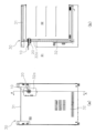
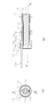
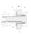
- FIG. 1 is a perspective view showing an external configuration of an incubator to which a cable cover according to an embodiment of the present invention is attached; 2A is a rear view of the incubator of FIG 1, and FIG. 2B is a cross-sectional view of the incubator of FIG 1 taken along line AA. 2 is a cross-sectional view showing a cable cover fixed to a measurement hole attached to the incubator of FIG. 1 and holding a cable.
- 4A is a front view showing the cable cover holding the cable of FIG. 3, and FIG. 4B is a cross-sectional view taken along line BB of FIG.
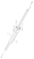
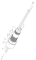
- FIG. 4 is an overall perspective view showing the configuration of a cable cover holding the cable shown in FIG. 3 .
- FIG. 6 is an exploded perspective view showing a configuration of components included in the cable cover of FIG.
- FIG. 7 is an assembly diagram showing a state in which a grommet included in the component configuration of FIG. 6 is attached to a cable.
- FIG. 8 is an assembly diagram showing a state in which a sleeve member is attached to the outer periphery of the grommet in FIG. 7 .
- 9 is an assembly diagram showing a state in which a nut member is attached to the outer periphery of the sleeve member in FIG. 8 .
- FIG. 10 is an assembly diagram showing a state in which a tip cap is attached to the tip of the sleeve member in FIG. 9 .
- FIG. 11 is an assembly diagram showing the state in which the cable cover holding the cable in FIG. 10 is inserted into the measurement hole.
- FIG. 12 is an assembly diagram showing a state in which a seal member is attached to the sleeve member of the cable cover inserted into the measurement hole of FIG. 11 from the internal space side of the incubator.
- FIG. 13 is an assembly diagram showing a state in which the sleeve member is pulled from the outside space side of the incubator in the state shown in FIG. 12 .
- 14 is an assembly diagram showing a state in which the nut member has been moved from the state shown in FIG. 13 to a position according to the size of the measurement hole and then tightened.
- FIG. 13A and 13B are side views showing cable covers attached to measurement holes of different lengths.
- 1A is a cross-sectional view showing a tapered portion provided on the inner peripheral surface side of the tip cap, FIG.
- FIG. 11 is a perspective view showing a configuration of a cable cover according to a second embodiment of the present invention.
- FIG. 18 is an exploded perspective view showing a component configuration of the cable cover of FIG. 17 .
- 18 is a cross-sectional view showing the state in which the cable cover of FIG. 17 is fixed to the measurement hole of the incubator of FIG. 1 .
- FIG. 11 is a perspective view showing a configuration of a cable cover according to a third embodiment of the present invention.
- FIG. 21 is an exploded perspective view showing the component configuration of the cable cover of FIG. 20 . 21 is a cross-sectional view showing a state in which the cable cover of FIG. 20 is fixed to the measurement hole of the incubator of FIG. 1 and holds the cable.
- the cable cover 10 of this embodiment fixes a cable C (see FIG. 7 , etc.) to a measurement hole (installation hole) 20 provided on the back surface (wall surface) 32 of an incubator (thermostat) 30, the cable cover 10 passing through the measurement hole 20 and pulled out from the internal space S2 to the external space S1.
- the incubator 30 has an internal space S2 formed in the housing 31 in which a measuring device (not shown) for performing various measurements, such as cell culture, is placed, and a cable C for supplying power to the measuring device and transmitting and receiving various signals is drawn out to the external space S1.
- the incubator 30 is set to create a high temperature and high humidity environment (e.g., 37 degrees and 80%) in the internal space S2 to maintain the environment for the cells being cultured. For this reason, when the temperature in the external space S1 is low (e.g., 25 degrees or lower), condensation may occur near the measurement hole 20 in the cable C drawn out from the internal space S2 to the external space S1 and on the inner wall near the measurement hole 20 in the internal space S2.
- the incubator 30 has a measurement hole 20 provided in a recess 32a provided in the back surface 32 in order to pull out a cable C from the internal space S2 of the housing portion 31 to the external space S1.
- the measurement hole 20 is a cylindrical member to which the cable cover 10 holding the cable C is fixed, and is provided in a through hole penetrating the rear surface 32. As shown in Fig. 3, the measurement hole 20 has a substantially cylindrical main body portion 20a and a flange portion 20b. As shown in FIG. 3, the substantially cylindrical main body portion 20a is inserted from the external space S1 side along the inner circumferential surface of a through hole formed in the rear surface 32, and fixed.
- the flange portion 20b is a flange-like portion formed on the external space S1 side of the substantially cylindrical main body portion 20a, and is provided so as to protrude radially outward from the outer circumferential surface at the end portion of the main body portion 20a on the external space S1 side.
- the flange portion 20b is fixed so as to abut against the surface of the back surface 32 on the external space S1 side.
- a cable cover 10 holding a cable C (see FIG. 7, etc.) is attached to the measurement hole 20.
- the cable cover 10 includes a grommet (retaining member) 11, a core sleeve (first sleeve member, sleeve member) 12, a heater (heating portion) 13, an outer sleeve (second sleeve member, sleeve member) 14, an intermediate member 15, a tip cap (cap member) 16, a sealing member 17, and a nut member (fixing member) 18.
- the grommet (holding member) 11 is, for example, a member made of silicone rubber, and encloses the cable C while elastically deforming, and holds the outer periphery of the cable C.
- the grommet 11 has a main body portion 11a that constitutes the central portion of the cable cover 10, and a holding portion 11b that holds four cables C (see FIG. 7, etc.).
- a configuration in which four cables C are held in the grommet 11 is described, but the number of cables C held, i.e., the number of holding portions 11b, is not limited to this.
- the main body 11a is a substantially cylindrical member and has grooves for holding the four cables C on its outer circumferential surface.
- the holding portion 11b is provided at the end of the main body portion 11a on the side of the internal space S2, and holds the cable C by pushing it through the notch 11ba (see Figs. 6 and 7) while being elastically deformed.
- the holding portions 11b that hold the four cables C connect the internal space S2 of the incubator 30 to the external space S1. Therefore, in this embodiment, the holding portions 11b are blocked using plugs (blocking members) 11c made of silicone rubber as shown in FIG. 5.
- the roughly cylindrical core sleeve (first sleeve member, sleeve member) 12 is, for example, a roughly cylindrical member made of aluminum having high thermal conductivity, and the grommet 11 is inserted and attached from its tip.
- a sheet-like heater 13 is wound around the outer circumferential surface of the core sleeve 12.
- the main body 12a is a substantially cylindrical member, and is provided with a flange 12b at the end on the external space S1 side.
- the flange portion 12b is a portion that protrudes radially outward from the outer circumferential surface of the main body portion 12a, and includes a portion that pulls out heater wiring 13a (see FIGS. 3 and 4(b)) of the heater 13 described later to the outside.
- the notch 12c is formed so as to divide the outer circumferential surface of the substantially cylindrical main body portion 12a into two along the axial direction. This makes it easier to attach the cable C held by the grommet 11 when inserting the grommet 11 from the tip of the core sleeve 12.
- the heater (heating section) 13 is arranged on the outer surface of the main body section 12a of the core sleeve 12, as shown in Figure 6, in order to heat a portion of the cable C near the measurement hole 20, and applies heat to the cable C held in the grommet 11 contained within the core sleeve 12.
- the heater wiring 13a is connected to the heater 13 provided on the outer peripheral surface of the main body 12a of the core sleeve 12 in order to supply power to the heater 13, and is drawn out to the external space S1.
- the supply of power from the heater wiring 13a to the heater 13 is stopped, and when the temperature falls below the set temperature, the supply of power to the heater 13 is started.
- the outer sleeve (second sleeve member, sleeve member) 14 is a substantially cylindrical member made of resin such as PC (polycarbonate) and is attached so as to cover the outer periphery of the core sleeve 12 and the heater 13. As shown in FIG. 6, the outer sleeve 14 has a main body portion 14a, a large diameter portion 14b, a small diameter portion 14c, threaded portions 14ca, 14cb, and a notch 14d.
- the main body 14a is configured by connecting two substantially cylindrical members (a large diameter portion 14b and a small diameter portion 14c) having different outer diameters.
- the large diameter portion 14b is a substantially cylindrical member on the side of the main body portion 14a that has a larger outer diameter, and contains the flange portion 12b of the core sleeve 12 therein.
- the small diameter portion 14 c is a substantially cylindrical member on the side of the main body portion 14 a that has a smaller outer diameter, and contains the heater 13 arranged on the outer circumferential surface of the main body portion 12 a of the core sleeve 12 .
- the screw portion (first screw portion) 14ca is formed along the longitudinal direction of the cable C on the outer peripheral surface at the middle portion of the substantially cylindrical main body portion 14a, and a nut member 18 described later is screwed into the screw portion 14ca.
- the threaded portion 14cb is formed on the outer peripheral surface of the end portion of the main body portion 14a on the internal space S2 side, and is fixed in a screwed state with a threaded portion 16c of the tip cap 16 described later.
- the notch 14d is formed so as to divide the outer peripheral surface of the substantially cylindrical main body portion 14a into two along the axial direction. Then, the core sleeve 12 is inserted from the tip of the outer sleeve 14 toward the inner peripheral surface side with the notch 14d open.
- the intermediate member 15 is a substantially cylindrical member that is disposed on the end (second end) side of the outer sleeve 14 on the internal space S2 side and has substantially the same outer diameter as the outer diameter of the outer sleeve 14.
- the intermediate member 15 has a main body portion 15a and a slit 15b.
- the main body 15 a is a substantially cylindrical member made of PTFE (Polytetrafluoroethylene) and is included in the inner circumferential surface side of the tip cap 16 .
- the slits 15b are formed in a network on the outer peripheral surface of the main body portion 15a along the longitudinal direction of the cable C.
- the tip cap (cap member) 16 is a substantially cylindrical member made of resin such as PC (polycarbonate) and is attached so as to cover the end of the outer sleeve 14 on the internal space S2 side and the outer circumferential surface of the intermediate member 15.
- the tip cap 16 has a main body portion 16a, a recessed portion 16b, a threaded portion 16c, and a tapered portion 16d.
- the main body 16a is a substantially cylindrical member.
- the recess 16b is a groove into which a seal member 17, which will be described later, fits, and is provided approximately in the center of the main body 16a.
- the threaded portion 16c screws into the above-mentioned threaded portion 14cb of the outer sleeve 14. This makes it possible to fix the tip cap 16 to the end of the outer sleeve 14 on the internal space S2 side.
- the tapered portion 16d is provided on the inner peripheral surface side of the substantially cylindrical main body portion 16a, and as shown in FIG. 16(a), is formed so that the inner diameter becomes smaller toward the internal space S2 side.
- the tapered portion 16d comes into contact with the outer circumferential surface of the body portion 15a of the intermediate member 15 and presses it toward the inner diameter side, as shown in Fig. 16(b). Therefore, when the attachment of the tip cap 16 to the tip of the outer sleeve 14 is completed, the portion of the body portion 15a of the intermediate member 15 that comes into contact with the tapered portion 16d elastically deforms toward the inner diameter side, as shown in Fig. 16(c), due to the slits 15b formed therein.
- the sealing member 17 is, for example, a substantially annular member made of silicone rubber, which is attached to the outer circumferential surface of the tip cap 16 and has an elastic main body portion 17a and a notch portion 17b. The sealing member 17 is inserted into the measurement hole 20 to seal the indoor space from the outdoor space.
- the main body portion 17a is a substantially annular elastically deformable member, and is attached to the recess 16b of the tip cap 16 with the notch portion 17b open.
- the notch 17b is formed so as to divide the outer peripheral surface of the substantially annular main body 17a in two along the axial direction, so that the main body 17a can be attached to the recess 16b of the tip cap 16 by opening the notch 17b while elastically deforming the main body 17a.
- the nut member 18 is a fastening member made of resin such as PC (polycarbonate), and as shown in FIG. 6, has a substantially annular body portion 18a and a threaded portion (second threaded portion) 18b formed on the inner periphery of the body portion 18a and threaded into the threaded portion 14ca on the outer sleeve 14 side.
- the nut member 18 is fixed at a position according to the length of the measurement hole 20 with the threaded portion 18b threaded into the threaded portion 14ca on the outer sleeve 14 side.
- the threaded portion 18b of the nut member 18 screws into the threaded portion 14ca formed near the center of the main body portion 14a of the outer sleeve 14, and does not screw into the threaded portion 14cb formed at the end portion on the internal space S2 side. That is, since the threaded portion 14cb has a smaller outer diameter than the threaded portion 14ca, the nut member 18 can be inserted into the threaded portion 14ca side without being screwed into the threaded portion 18b of the nut member 18.
- the main body 11a of the grommet 11 is elastically deformed, and the notches 11ba formed in the four holding portions 11b are opened to hold the cable C in the holding portions 11b.
- a plug 11c is inserted into the holding portion 11b that does not hold the cable C, as shown in FIG.
- sleeve members core sleeve 12 and outer sleeve 14
- the grommet 11 is inserted from the tip of the core sleeve 12 and is held on the inner peripheral surface side.
- the nut member 18 is attached so as to be screwed onto the threaded portion 14ca provided on the outer periphery of the outer sleeve 14 .
- the nut member 18 moves while rotating to the end on the external space S1 side in a state where it is screwed onto the threaded portion 14ca.
- the tip cap 16 is attached to the end of the small diameter portion 14c in the body portion 14a of the outer sleeve 14.
- the tip cap 16 is fixed by screwing a threaded portion 16c formed on the inner circumferential surface of the tip cap 16 into a threaded portion 14cb formed on the end of the small diameter portion 14c.
- the configuration shown in FIG. 10 is inserted into the measurement hole 20 fixed in the recess 32 a in the rear surface 32 of the housing part 31 of the incubator 30 from the external space S 1 side.
- FIG. 10 the configuration of FIG. 10 is inserted until the nut member 18 attached to the threaded portion 14ca of the large diameter portion 14b of the outer sleeve 14 abuts against the flange portion 20b of the measurement hole 20, as shown in FIG.
- the seal member 17 is attached to the recess 16b of the body 16a of the tip cap 16 from the internal space S2 side by opening the cut portion 17b of the body 17a.
- the outer sleeve 14 is pulled toward the external space S1 as shown in FIG. At this time, the end of the body portion 20 a of the measurement hole 20 on the internal space S ⁇ b>2 side moves to a position where it abuts against the body portion 17 a of the seal member 17 .
- the nut member 18 is rotated to move over the threaded portion 14ca of the outer sleeve 14 toward the internal space S2 as shown in Figure 14, and the nut member 18 is fixed at a position where it presses against the flange portion 20b of the measurement hole 20.
- the cable cover 10 is fixed to the measurement hole 20 attached to the rear surface 32 of the housing portion 31 of the incubator 30. Then, with the cable cover 10 holding multiple cables C and fixed to the measurement hole 20 attached to the back surface 32 of the incubator 30, electricity is passed through the heater 13 to heat the cables C near the measurement hole 20.
- the length of the measurement hole 20 of the thermostatic chamber such as the incubator 30 to which the cable cover 10 of this embodiment is attached may differ depending on the device.
- the cable cover 10 of this embodiment can be attached to both measurement holes 20, 120 of different lengths by changing the position at which the nut member 18 that screws into the threaded portion 14ca provided on the outer peripheral surface of the outer sleeve 14 is fixed. More specifically, assuming that the length of the measurement hole 20 is L1 and the length of the measurement hole 120 is L2, when L1 ⁇ L2, as shown in Figure 15 (a), the nut member 18 moves significantly for the short measurement hole 20 to a position where it abuts the flange portion 20b, thereby fixing the cable cover 10.
- the nut member 18 is moved slightly to a position where it abuts against the flange portion 120b of the long measurement hole 120, thereby fixing the cable cover 10.
- the cable cover 10 of this embodiment can be attached to each of the measurement holes 20, 120 even if the measurement holes 20, 120 attached to an incubator such as an incubator 30 have different lengths.
- FIG. 17 to 19 show a state in which the cable cover 110 does not hold the cable C.
- the cable cover 110 of this embodiment fixes a cable C (see Figure 7, etc.) that is pulled out from the internal space S2 to the external space S1 through a measurement hole 20 attached to an incubator 30 or other incubator.
- the cable cover 110 has a grommet (holding member) 111, a core sleeve (first sleeve member) 112, a seat heater (heating portion) 113, and an outer sleeve (second sleeve member) 114.
- the grommet (holding member) 111 is, for example, a member made of silicone rubber, which encloses the cable C while elastically deforming and holds the outer periphery of the cable C.
- the grommet 111 has a main body portion 111a that constitutes the central portion of the cable cover 110, a cylindrical portion 111b that is connected to the main body portion 111a and has an outer diameter larger than that of the main body portion 111a, and a holding portion 111c that holds four cables C (see FIG. 7, etc.).
- the grommet 111 also has notches 111ba provided on the outer circumferential surface of the cylindrical portion 111b, which elastically deform when the cable C is held by the holding portion 111c, thereby moving the cable C to the holding portion 111c.
- the holding parts 111c that hold the four cables C are blocked with resin plugs (blocking members) 111d. This makes it possible to prevent the internal space S2 and the external space S1 of the incubator 30 from communicating with each other through the holding parts 111c that do not hold the cables C.
- the grommet 111 has a press-fit portion 111e that abuts against the inner peripheral surface of the measurement hole 20 when installed in the measurement hole 20 and is held in place by the elastic deformation of the cylindrical portion 111b.
- the core sleeve (first sleeve member) 112 is a member that is made, for example, by cutting aluminum and is arranged on the outer periphery of the grommet 111, and as shown in FIG. 18, has a substantially cylindrical main body portion 112a and a notch portion 112ab provided along the longitudinal direction of the main body portion 112a.
- the notch portion 112ab is a gap formed along the longitudinal direction so as to divide the substantially cylindrical main body portion 112a in the circumferential direction.
- the sheet heater (heating section) 113 is arranged on the outer surface of the main body section 112a of the core sleeve 112, as shown in Figure 19, in order to heat a portion of the cable C near the measurement hole 20, and applies heat to the cable C held in the grommet 111 contained within the core sleeve 112.
- the seat heater 113 has a main body 113a, a retainer 113b, and heater wiring 113c.
- the main body portion 113a is a sheet-like member and has a connection portion 113aa that is connected to the heater wiring 113c, and a notch portion 113ab formed along the longitudinal direction so as to divide the approximately cylindrical main body portion 113a in the circumferential direction.
- the retainer 113b is a member that retains the heater wire 113c so that it does not come loose, and is attached to the exterior space S1 side of the main body 113a.
- the heater wiring 113c is connected to the connection portion 113aa of the main body portion 113a, is provided to supply power to the seat heater 113, and is drawn out to the external space S1.
- the supply of power from the heater wiring 113c to the seat heater 113 is stopped, and when the temperature falls below the set temperature, the supply of power to the seat heater 113 is started.
- the outer sleeve (second sleeve member) 114 is made, for example, by cutting resin, and is a member that is arranged on the outer peripheral surface side of the core sleeve 112 and the seat heater 113. As shown in FIG. 18, it has a substantially cylindrical main body portion 114a, an arc portion 114aa provided at the end of the main body portion 114a facing the external space S1, and a notch portion 114ab provided along the longitudinal direction of the main body portion 114a.
- the arc portion 114aa is provided at the end of the main body portion 114a facing the external space S1, and is formed so that the end of the main body portion 114a is divided in the circumferential direction, and is a generally arc-shaped portion when viewed from the external space S1 side.
- the connecting portion 113aa described above is arranged to abut against the divided portion in the circumferential direction where the arc portion 114aa is provided, as shown in Figures 17 and 19.
- the notch 114ab is formed along the longitudinal direction so as to divide the substantially cylindrical main body 114a in the circumferential direction.
- the grommet 111 is inserted from the tip side of the outer sleeve 114 and is held on the inner circumferential surface side of the main body 114a.
- the grommet 111 has a press-fit portion 111e that abuts against the inner surface of the measurement hole 20 when installed in the measurement hole 20 and is held in place by elastic deformation of the cylindrical portion 111b (see Figure 19).
- the seat heater 113 is arranged on the outer peripheral surface of the main body portion 112a of the core sleeve 112, and applies heat to the cable C held in the grommet 111 contained in the core sleeve 112.
- FIG. 3 A cable cover 210 according to still another embodiment of the present invention will be described below with reference to Figures 20 to 22.
- Figures 20 and 21 show the cable cover 210 in a state where it does not hold the cable C
- Figure 22 shows the cable cover 210 in a state where it holds the cable C.
- the cable cover 210 of the present embodiment fixes a cable C (see Figure 22, etc.) that is pulled out from the internal space S2 to the external space S1 through a measurement hole 20 attached to an incubator 30 or other incubator.
- the cable cover 210 has a silicon plug (second holding member) 211 , an aluminum block (first holding member) 212 , and a cartridge heater (heating portion) 213 .
- the silicone plug (second holding member) 211 is the member that constitutes the cable cover 210 and is disposed closest to the internal space S2.
- the silicone plug 211 is disposed so as to abut against the aluminum block (first holding member) 212 in the extension direction of the cable C, and has a main body 211a, a holding portion 211aa, and a notch 211ab.
- the main body 211a is formed of, for example, a substantially cylindrical elastic member made of silicone rubber.
- the holding portions 211aa are four through holes provided along the longitudinal direction of the main body portion 211a, and hold the cables C. This allows the cable cover 210 to hold four cables C at the four holding portions 211aa.
- the notches 211ab are provided on the outer circumferential surface of the main body 211a, and elastically deform to open when the cable C is held by the holding portion 211aa, thereby moving the cable C to the holding portion 211aa.
- the holding parts 211aa that hold the four cables C are blocked with resin plugs (blocking members) 211b. This makes it possible to prevent the internal space S2 and the external space S1 of the incubator 30 from communicating with each other through the holding parts 211aa that do not hold the cables C.
- the silicon plug 211 has a press-fit portion 211c that contacts the inner circumferential surface of the measurement hole 20 when installed in the measurement hole 20 and is held in place by elastic deformation.
- the press-fit portion 211c abuts against the inner peripheral surface of the measurement hole 20 and is held in place by the elastic deformation of the main body portion 211a (see FIG. 22). This makes it possible to easily fix the cable cover 210 to the measurement hole 20 by utilizing the elasticity of the silicone plug 211 and pressing it in so that the outer surface of the silicone plug 211 abuts against the inner surface of the measurement hole 20.
- the aluminum block (first holding member) 212 is formed by cutting a block of aluminum, and has a substantially cylindrical main body portion 212a, multiple holding portions 212aa provided on the main body portion 212a, and a substantially cylindrical insertion hole 212ab provided in the center of the main body portion 212a.
- the insertion hole 212ab is a through hole formed along the central axis of the substantially cylindrical main body portion 212a, and has an inner diameter slightly larger than the outer diameter of the main body portion 213a of the cartridge heater 213.
- the cartridge heater 213 is inserted into the insertion hole 212ab.
- the multiple holding portions 212aa are provided on the outer periphery of the insertion hole, and each holds a cable C.
- a configuration in which four cables C are held in the aluminum block 212 will be described, but the number of cables C held, i.e., the number of holding portions 212aa, is not limited to this.
- the aluminum block 212 has a plurality of holding portions 212aa provided on the outer circumferential surface of the main body portion 212a.
- the multiple holding portions 212aa are provided along the longitudinal direction at approximately equal angular intervals on the outer circumferential surface of the approximately cylindrical main body portion 212a, and are recesses into which the cable C is fitted from the outer circumferential side.
- the aluminum block 212 is made of a metal material having high thermal conductivity, such as aluminum, so that the heat generated by the cartridge heater 213 can be efficiently transferred to the cable C.
- the cartridge heater (heating unit) 213 is a rod-shaped heating element, and as shown in Fig. 22, is inserted into an insertion hole 212ab formed along the central axis of the aluminum block 212.
- the cartridge heater 213 has a main body 213a, a flange 213b, heater wiring 213c, and a screw 213d.
- the main body 213a is a substantially cylindrical rod-shaped member, and is connected to the heater wiring 213c.
- the flange portion 213b is a portion that protrudes radially outward from the outer circumferential surface of the substantially cylindrical main body portion 213a, and is fixed to the end surface of the aluminum block 212 by means of screws 213d.
- the flange portion 213b may be fixed to the aluminum block 212 by other means such as an adhesive instead of by screws.
- the heater wiring 213c is connected to the main body 213a, is provided to supply power to the cartridge heater 213, and is drawn out to the external space S1.
- the power supply from the heater wiring 213c to the cartridge heater 213 is stopped, and when the temperature falls below the set temperature, the power supply to the cartridge heater 213 is started.
- the cable cover 210 of this embodiment has a press-fit portion 211c in which the silicone plug 211 abuts against the inner surface of the measurement hole 20 when installed in the measurement hole 20 and is held in place by elastic deformation of the main body portion 211a (see Figure 22).
- This makes it possible to easily fix the cable cover 210 to the measurement hole 20 by utilizing the elasticity of the silicone plug 211 and pressing it in so that the outer surface of the silicone plug 211 abuts against the inner surface of the measurement hole 20 without using fixing members such as screws.
- the cartridge heater 213 is disposed near the central axis of the main body 212 a of the aluminum block 212 , and applies heat to the cable C held on the outer circumferential surface side of the aluminum block 212 . This allows a portion of the cable C near the measurement hole 20 to be heated, thereby effectively preventing condensation from forming on the surface of the cable C.
- the sleeve member may be of unitary construction.
- a substantially cylindrical member (measurement hole 20) is fixed to the back surface (wall surface) 32 on the incubator 30 side to which the cable cover 10 is attached.
- the present invention is not limited to this.
- the incubator to which the cable cover is attached may be configured to be directly attached to a wall surface.
- C In the above embodiment, an example has been described in which the sheet-shaped heater 13 is wound around the outer circumferential surface of the core sleeve 12 in order to prevent condensation from occurring near the measurement hole 20.
- the present invention is not limited to this.
- the heating portion for preventing condensation may be in a form other than a sheet form.
- the cable cover 10 of the present embodiment holds four cables C.
- the present invention is not limited to this.
- the cable cover may be configured to hold one to three cables, or may be configured to hold five or more cables.
- the incubator 30 for cell culture has been described as an example of the incubator to which the cable cover 10 of the present embodiment is attached.
- the present invention is not limited to this.
- the thermostat to which the cable cover is attached is not limited to an incubator, but may be any of various thermostats used in high temperature and/or high humidity environments.
- the silicon plug (second holding member) 211 and the aluminum block (first holding member) 212 are provided as separate members.
- the present invention is not limited to this.
- the first holding member and the second holding member may be configured as an integrated member.
- the occurrence of condensation on the surface of the cable can be effectively suppressed by heating the cable using a heating element such as a heater while the cable is held in a member formed by integrating the first and second holding members.
- a heating element such as a heater
- the cable cover can be easily fixed to the measurement hole by press-fitting, as in the above embodiments 2 and 3.
- the cable cover of the present invention is a cable cover that secures a cable that is pulled out from the inside to the outside through an opening provided in the wall of an incubator, and has the effect of more effectively preventing condensation from occurring near the opening, making it widely applicable to various devices in which cables are pulled from the inside to the outside of the room.
Landscapes
- Engineering & Computer Science (AREA)
- Structural Engineering (AREA)
- Chemical & Material Sciences (AREA)
- Civil Engineering (AREA)
- Architecture (AREA)
- Wood Science & Technology (AREA)
- Zoology (AREA)
- Bioinformatics & Cheminformatics (AREA)
- Health & Medical Sciences (AREA)
- Organic Chemistry (AREA)
- Life Sciences & Earth Sciences (AREA)
- Microbiology (AREA)
- Biotechnology (AREA)
- Sustainable Development (AREA)
- Biochemistry (AREA)
- General Engineering & Computer Science (AREA)
- General Health & Medical Sciences (AREA)
- Genetics & Genomics (AREA)
- Physics & Mathematics (AREA)
- Biomedical Technology (AREA)
- Analytical Chemistry (AREA)
- Thermal Sciences (AREA)
- Cable Accessories (AREA)
- Apparatus Associated With Microorganisms And Enzymes (AREA)
- Insulating Bodies (AREA)
Priority Applications (3)
| Application Number | Priority Date | Filing Date | Title |
|---|---|---|---|
| EP23871414.1A EP4550955A1 (en) | 2022-09-29 | 2023-07-25 | Cable cover and constant-temperature unit provided with same |
| JP2024549788A JPWO2024070171A1 (https=) | 2022-09-29 | 2023-07-25 | |
| US19/040,529 US20250193972A1 (en) | 2022-09-29 | 2025-01-29 | Cable cover and constant-temperature unit equipped with same |
Applications Claiming Priority (2)
| Application Number | Priority Date | Filing Date | Title |
|---|---|---|---|
| JP2022-156335 | 2022-09-29 | ||
| JP2022156335 | 2022-09-29 |
Related Child Applications (1)
| Application Number | Title | Priority Date | Filing Date |
|---|---|---|---|
| US19/040,529 Continuation US20250193972A1 (en) | 2022-09-29 | 2025-01-29 | Cable cover and constant-temperature unit equipped with same |
Publications (1)
| Publication Number | Publication Date |
|---|---|
| WO2024070171A1 true WO2024070171A1 (ja) | 2024-04-04 |
Family
ID=90477069
Family Applications (1)
| Application Number | Title | Priority Date | Filing Date |
|---|---|---|---|
| PCT/JP2023/027152 Ceased WO2024070171A1 (ja) | 2022-09-29 | 2023-07-25 | ケーブルカバーおよびこれを備えた恒温器 |
Country Status (4)
| Country | Link |
|---|---|
| US (1) | US20250193972A1 (https=) |
| EP (1) | EP4550955A1 (https=) |
| JP (1) | JPWO2024070171A1 (https=) |
| WO (1) | WO2024070171A1 (https=) |
Citations (8)
| Publication number | Priority date | Publication date | Assignee | Title |
|---|---|---|---|---|
| JPS58103178U (ja) * | 1981-12-28 | 1983-07-13 | 富士通フアナツク株式会社 | コ−ドグリツプ |
| JPS6232583U (https=) * | 1985-08-14 | 1987-02-26 | ||
| JPH05240563A (ja) * | 1992-02-28 | 1993-09-17 | Sanyo Electric Co Ltd | 冷蔵庫の結露防止装置 |
| JPH1117363A (ja) * | 1997-06-23 | 1999-01-22 | Tokyo Gas Co Ltd | 部材のシール構造 |
| US6037544A (en) * | 1997-11-22 | 2000-03-14 | Lg Chemical Ltd | Splice closure for telecommunications cables |
| JP2009178070A (ja) | 2008-01-30 | 2009-08-13 | Sanyo Electric Co Ltd | 恒温装置およびカバー |
| JP2015115154A (ja) * | 2013-12-11 | 2015-06-22 | オーウエル株式会社 | 照明装置 |
| CN217341455U (zh) * | 2022-04-08 | 2022-09-02 | 江苏佳世德检测技术有限公司 | 一种高低温试验箱出线孔智能防冷凝装置 |
-
2023
- 2023-07-25 WO PCT/JP2023/027152 patent/WO2024070171A1/ja not_active Ceased
- 2023-07-25 JP JP2024549788A patent/JPWO2024070171A1/ja active Pending
- 2023-07-25 EP EP23871414.1A patent/EP4550955A1/en active Pending
-
2025
- 2025-01-29 US US19/040,529 patent/US20250193972A1/en active Pending
Patent Citations (9)
| Publication number | Priority date | Publication date | Assignee | Title |
|---|---|---|---|---|
| JPS58103178U (ja) * | 1981-12-28 | 1983-07-13 | 富士通フアナツク株式会社 | コ−ドグリツプ |
| JPS6232583U (https=) * | 1985-08-14 | 1987-02-26 | ||
| JPH05240563A (ja) * | 1992-02-28 | 1993-09-17 | Sanyo Electric Co Ltd | 冷蔵庫の結露防止装置 |
| JPH1117363A (ja) * | 1997-06-23 | 1999-01-22 | Tokyo Gas Co Ltd | 部材のシール構造 |
| US6037544A (en) * | 1997-11-22 | 2000-03-14 | Lg Chemical Ltd | Splice closure for telecommunications cables |
| JP2009178070A (ja) | 2008-01-30 | 2009-08-13 | Sanyo Electric Co Ltd | 恒温装置およびカバー |
| JP5017133B2 (ja) | 2008-01-30 | 2012-09-05 | 三洋電機株式会社 | 恒温装置およびカバー |
| JP2015115154A (ja) * | 2013-12-11 | 2015-06-22 | オーウエル株式会社 | 照明装置 |
| CN217341455U (zh) * | 2022-04-08 | 2022-09-02 | 江苏佳世德检测技术有限公司 | 一种高低温试验箱出线孔智能防冷凝装置 |
Also Published As
| Publication number | Publication date |
|---|---|
| US20250193972A1 (en) | 2025-06-12 |
| JPWO2024070171A1 (https=) | 2024-04-04 |
| EP4550955A1 (en) | 2025-05-07 |
Similar Documents
| Publication | Publication Date | Title |
|---|---|---|
| US6045112A (en) | Vibration isolation system for an electric motor | |
| US20090149069A1 (en) | Electrical-connection device, particularly for photovoltaic-cell solar panels | |
| US8698011B2 (en) | Device for fixing a cable to a cable outlet connector | |
| RU118478U1 (ru) | Уплотнительная система | |
| GB2043816A (en) | Connector fitting | |
| US9755412B2 (en) | Grommet for mounting cable gland or the like | |
| US20120049422A1 (en) | Slotted spring vibration isolator | |
| JP5276623B2 (ja) | ケーブルグランド及びケーブルグランド用ワッシャ | |
| WO2024070171A1 (ja) | ケーブルカバーおよびこれを備えた恒温器 | |
| SE463275B (sv) | Armatur foer en termostatventil | |
| EP3078853B1 (en) | Thermoactuator and attachment structure thereof | |
| US11035458B2 (en) | Deceleration device | |
| JP2012077910A (ja) | ケーブルを張力逃し式に固定するための装置 | |
| CN105896179B (zh) | 一种浮动快插转接器 | |
| CZ294403B6 (cs) | Ovládací nástavec ventilu topení | |
| JP2020172954A (ja) | 防塵キャップ、防塵キャップ取付構造及び防塵キャップ取付方法 | |
| JP6156159B2 (ja) | 端子台 | |
| JP2024037060A (ja) | ケーブルグランド | |
| WO2020084857A1 (ja) | 取付部材 | |
| EP4231465A1 (en) | Electronic device and waterproof member thereof | |
| JPWO2024070171A5 (https=) | ||
| JP2018098828A (ja) | ケーブルグランド | |
| CZ2006210A3 (cs) | Usporádání regulátoru v tepelné izolaci armaturových sestav | |
| JP2024037059A (ja) | ケーブルグランド | |
| WO2020084856A1 (ja) | ケーブルグランド |
Legal Events
| Date | Code | Title | Description |
|---|---|---|---|
| 121 | Ep: the epo has been informed by wipo that ep was designated in this application |
Ref document number: 23871414 Country of ref document: EP Kind code of ref document: A1 |
|
| WWE | Wipo information: entry into national phase |
Ref document number: 2024549788 Country of ref document: JP |
|
| WWE | Wipo information: entry into national phase |
Ref document number: 2023871414 Country of ref document: EP |
|
| ENP | Entry into the national phase |
Ref document number: 2023871414 Country of ref document: EP Effective date: 20250203 |
|
| NENP | Non-entry into the national phase |
Ref country code: DE |
|
| WWP | Wipo information: published in national office |
Ref document number: 2023871414 Country of ref document: EP |