WO2020084856A1 - ケーブルグランド - Google Patents
ケーブルグランド Download PDFInfo
- Publication number
- WO2020084856A1 WO2020084856A1 PCT/JP2019/030439 JP2019030439W WO2020084856A1 WO 2020084856 A1 WO2020084856 A1 WO 2020084856A1 JP 2019030439 W JP2019030439 W JP 2019030439W WO 2020084856 A1 WO2020084856 A1 WO 2020084856A1
- Authority
- WO
- WIPO (PCT)
- Prior art keywords
- cable
- cap
- ferrite core
- gland
- case
- Prior art date
Links
- 229910000859 α-Fe Inorganic materials 0.000 claims abstract description 64
- 210000004907 gland Anatomy 0.000 claims description 74
- 238000003780 insertion Methods 0.000 claims description 35
- 230000037431 insertion Effects 0.000 claims description 35
- 230000002093 peripheral effect Effects 0.000 claims description 28
- 210000000078 claw Anatomy 0.000 description 11
- 239000000463 material Substances 0.000 description 3
- 239000011347 resin Substances 0.000 description 3
- 229920005989 resin Polymers 0.000 description 3
- 230000008878 coupling Effects 0.000 description 2
- 238000010168 coupling process Methods 0.000 description 2
- 238000005859 coupling reaction Methods 0.000 description 2
- 239000000428 dust Substances 0.000 description 2
- 239000003921 oil Substances 0.000 description 2
- XLYOFNOQVPJJNP-UHFFFAOYSA-N water Substances O XLYOFNOQVPJJNP-UHFFFAOYSA-N 0.000 description 2
- 230000007423 decrease Effects 0.000 description 1
- 239000000696 magnetic material Substances 0.000 description 1
- 238000000034 method Methods 0.000 description 1
- 238000012986 modification Methods 0.000 description 1
- 230000004048 modification Effects 0.000 description 1
Images


Classifications
-
- H—ELECTRICITY
- H01—ELECTRIC ELEMENTS
- H01F—MAGNETS; INDUCTANCES; TRANSFORMERS; SELECTION OF MATERIALS FOR THEIR MAGNETIC PROPERTIES
- H01F17/00—Fixed inductances of the signal type
- H01F17/04—Fixed inductances of the signal type with magnetic core
- H01F17/06—Fixed inductances of the signal type with magnetic core with core substantially closed in itself, e.g. toroid
-
- H—ELECTRICITY
- H02—GENERATION; CONVERSION OR DISTRIBUTION OF ELECTRIC POWER
- H02G—INSTALLATION OF ELECTRIC CABLES OR LINES, OR OF COMBINED OPTICAL AND ELECTRIC CABLES OR LINES
- H02G15/00—Cable fittings
- H02G15/02—Cable terminations
-
- H—ELECTRICITY
- H02—GENERATION; CONVERSION OR DISTRIBUTION OF ELECTRIC POWER
- H02G—INSTALLATION OF ELECTRIC CABLES OR LINES, OR OF COMBINED OPTICAL AND ELECTRIC CABLES OR LINES
- H02G3/00—Installations of electric cables or lines or protective tubing therefor in or on buildings, equivalent structures or vehicles
- H02G3/22—Installations of cables or lines through walls, floors or ceilings, e.g. into buildings
-
- H—ELECTRICITY
- H05—ELECTRIC TECHNIQUES NOT OTHERWISE PROVIDED FOR
- H05K—PRINTED CIRCUITS; CASINGS OR CONSTRUCTIONAL DETAILS OF ELECTRIC APPARATUS; MANUFACTURE OF ASSEMBLAGES OF ELECTRICAL COMPONENTS
- H05K7/00—Constructional details common to different types of electric apparatus
-
- H—ELECTRICITY
- H05—ELECTRIC TECHNIQUES NOT OTHERWISE PROVIDED FOR
- H05K—PRINTED CIRCUITS; CASINGS OR CONSTRUCTIONAL DETAILS OF ELECTRIC APPARATUS; MANUFACTURE OF ASSEMBLAGES OF ELECTRICAL COMPONENTS
- H05K9/00—Screening of apparatus or components against electric or magnetic fields
Definitions
- the present invention relates to a cable gland.
- the cable gland of Patent Document 1 includes a gland body that can be attached to a case, a cap that is fastened to the gland body, and a sleeve that is press-fitted between the gland body and the cable when the cap is fastened.
- a gland body that can be attached to a case
- a cap that is fastened to the gland body
- a sleeve that is press-fitted between the gland body and the cable when the cap is fastened.
- the cable gland of Patent Document 2 is formed in a cylindrical shape, a fixing screw portion is formed on the outer peripheral surface, and a ferrite core is attached to the inner peripheral surface.
- the ferrite core has a hole through which the cable is inserted. In this cable gland, the ferrite core can reduce the noise of the cable.
- the above-described cable gland of Patent Document 1 can suppress the entry of foreign matter into the case, but has the problem that the noise of the cable cannot be reduced. Further, with the cable gland of Patent Document 2 described above, it is possible to reduce the noise of the cable, but there is a risk that foreign matter may enter through the gap between the ferrite core and the cable.
- the present invention has been made to solve the above problems, and an object of the present invention is to provide a cable gland capable of reducing the noise of a cable while suppressing the intrusion of foreign matter into the case. It is to be.
- the cable gland according to the present invention is for attaching a cable to a case, and includes a gland body attachable to the case, a cap clamped to the gland body, a sleeve press-fitted between the gland body and the cable, and a cable. And a ferrite core for noise reduction. The ferrite core is attached to the cap.
- the gap between the gland body and the cable can be filled with the sleeve, so that foreign matter can be prevented from entering the case. Also, the ferrite core can reduce the noise of the cable.
- the cap in the cable gland, includes a cylindrical side peripheral wall portion and a top wall portion formed at one end of the side peripheral wall portion, and the top wall portion has a first insertion hole through which a cable is inserted.
- the inner peripheral surface of the side peripheral wall portion is formed with a female screw portion on the other end side, and the ferrite core is formed in an annular shape so that the cable can be inserted therethrough. It may be arranged between the wall portion and the female screw portion.
- an attachment member for attaching the ferrite core to the cap may be provided.
- the mounting member includes a circular plate portion having a second insertion hole through which a cable is inserted, a mounting portion disposed on one surface side of the plate portion, and another surface side of the plate portion. And a holding part disposed on the plate part, the mounting part being formed on an inner edge part of the plate part and configured to be attached to the cap, and the holding part being formed on an outer edge part of the plate part, for holding the ferrite core. It may be configured as follows.
- the mounting portion may have a snap-fit structure and may be configured to be fitted into the first insertion hole of the top wall portion of the cap.
- the holding portion may have a snap-fit structure and may be configured to hold the ferrite core from the outer peripheral surface side.
- the gland body includes a cylindrical body portion into which the cable is inserted, and a flange portion protruding outward from the other end portion of the body portion.
- the flange portion is configured to be attachable to the case, the outer peripheral surface of the main body portion is formed with a male screw portion to be screwed with the female screw portion, and the sleeve has a cylindrical shape so that the cable can be inserted therethrough.
- the sleeve may be formed so that the sleeve is pressed by the ferrite core when the cap is fastened to the gland body, and the sleeve is press-fitted between the body portion and the cable.
- the cable gland of the present invention it is possible to reduce the noise of the cable while suppressing the entry of foreign matter into the case.
- FIG. 6 is a perspective view showing a state where the ferrite core is held by the holder of FIG. 5.
- FIG. 7 is a perspective view showing a state where the holder of FIG. 6 is attached to a cap.
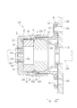
- the cable gland 100 is provided for attaching the cable 150 to the case 160, as shown in FIG.
- the cable gland 100 is configured to fix the cable 150 inserted through the insertion hole 161 of the case 160 to the case 160.
- the cable 150 is a power cable that connects a motor and an inverter (not shown), and the case 160 is an inverter case that houses the inverter.
- the side where the cable gland 100 is attached to the case 160 (X1 direction side) is the outside of the case 160, and the opposite side (X2 direction side) is the inside of the case 160.
- the cable gland 100 includes a gland body 1, a cap 2, a sleeve 3, a ferrite core 4, and a holder 5.
- the holder 5 is an example of the "mounting member" in the present invention.
- the ground body 1 is configured to be attachable to the case 160.
- This gland main body 1 is made of resin, for example, and has a cylindrical main body portion 11 through which the cable 150 is inserted, and a flange portion 12 that projects outward from the other end portion (end portion on the X2 direction side) of the main body portion 11. Is included.
- a male screw portion 13 with which the cap 2 is screwed is formed on the outer peripheral surface of the main body portion 11.
- a large-diameter portion 14a, a reduced-diameter portion (tapered portion) 14b, and a small-diameter portion 14c are formed on the inner peripheral surface of the main body portion 11 so as to be continuous with each other.
- the large diameter portion 14a is arranged on one side (X1 direction side), the small diameter portion 14c is arranged on the other side (X2 direction side), and the reduced diameter portion 14b is arranged between the large diameter portion 14a and the small diameter portion 14c. There is.
- the reduced diameter portion 14b is formed so that the opening diameter gradually decreases toward the flange portion 12 side (X2 direction side).
- the flange portion 12 is configured to be attachable to the case 160, and when the flange portion 12 is attached to the case 160, the small diameter portion 14c is fitted in the insertion hole 161 of the case 160.
- a bolt insertion hole 15 is formed in the flange portion 12 and a bolt insertion hole 162 is formed in the case 160, and a bolt (not shown) inserted in the bolt insertion holes 15 and 162 is fastened.
- the flange portion 12 is attached to the case 160.
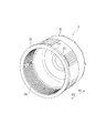
- the cap 2 is configured so that it can be fastened to the gland body 1.
- the cap 2 is made of resin, for example, and as shown in FIG. 4, a cylindrical side peripheral wall portion 21 and a top wall portion formed at one end portion (end portion on the X1 direction side) of the side peripheral wall portion 21. 22 and 22 are included.
- the top wall portion 22 has an insertion hole 23 through which the cable 150 is inserted.
- a female screw portion 24 that is screwed into the male screw portion 13 is formed on the other end side (X2 direction side) of the inner peripheral surface of the side peripheral wall portion 21.
- the cap 2 is provided with an accommodating portion 25 in which the ferrite core 4 is accommodated between the top wall portion 22 and the female screw portion 24 in the side peripheral wall portion 21.
- the insertion hole 23 is an example of the "first insertion hole" in the present invention.
- the sleeve 3 is made of rubber, for example, and is elastically deformable.
- the sleeve 3 is formed in a cylindrical shape so that the cable 150 can be inserted therethrough.
- the sleeve 3 is configured to be press-fitted between the main body portion 11 of the gland main body 1 and the cable 150.
- the ferrite core 4 is made of a magnetic material and is provided to reduce noise of the cable 150.
- the ferrite core 4 is vulnerable to impact and is formed into an annular shape so that the cable 150 can be inserted therethrough.
- the ferrite core 4 is attached to the cap 2 by the holder 5 and housed in the housing portion 25 of the cap 2.
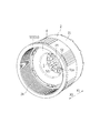
- the holder 5 is provided to attach the ferrite core 4 to the cap 2, as shown in FIG. 7. That is, the holder 5 is interposed between the cap 2 and the ferrite core 4, and is made of, for example, a thin plate material.
- the holder 5 is made of resin, for example, and includes a plate portion 51, a mounting portion 52, and a holding portion 53, as shown in FIG.
- the plate portion 51 is formed in a substantially circular shape, and has an insertion hole 51a in the center thereof through which the cable 150 is inserted.
- the mounting portion 52 is arranged on one surface side (X1 direction side) of the plate portion 51, and the holding portion 53 is arranged on the other surface side (X2 direction side) of the plate portion 51.
- the insertion hole 51a is an example of the "second insertion hole" in the present invention.
- the attachment part 52 is configured to be attached to the cap 2.
- the mounting portions 52 are formed on the inner edge portion of the plate portion 51, and a plurality of mounting portions 52 are provided at predetermined intervals in the circumferential direction. That is, the plurality of mounting portions 52 are arranged in a circle so as to surround the insertion hole 51a. For example, the six mounting portions 52 are arranged at intervals of 60 degrees.
- Each of the mounting portions 52 has a pair of arm portions 521 extending from the plate portion 51 to one side (X1 direction side), a coupling portion 522 that couples the tips of the pair of arm portions 521, and a radial outward direction protruding from the coupling portion 522. And a claw portion 523 that operates.
- the arm portion 521 is configured to be elastically deformable in the radial direction. As shown in FIG. 1, the claw portion 523 is adapted to be engaged with the outer surface (the surface on the X1 direction side) of the top wall portion 22 of the cap 2. That is, each mounting portion 52 has a snap-fit structure and is configured to be fitted into the insertion hole 23 of the top wall portion 22 of the cap 2.
- the holding portion 53 is configured to hold the ferrite core 4, as shown in FIG.
- the holding portions 53 are formed on the outer edge of the plate portion 51, and a plurality of holding portions 53 are provided at predetermined intervals in the circumferential direction. That is, the plurality of holding portions 53 are arranged in a circle so as to surround the plate portion 51.
- the holding portions 53 are arranged so as to be displaced in the circumferential direction with respect to the mounting portions 52, and the mounting portions 52 and the holding portions 53 are alternately arranged in the circumferential direction.
- the six holding portions 53 are arranged at intervals of 60 degrees, and the holding portions 53 are displaced from the mounting portion 52 by 30 degrees.
- Each holding portion 53 has a pair of arm portions 531 extending from the plate portion 51 to the other side (X2 direction side), a connecting portion 532 that connects the tips of the pair of arm portions 531, and projects radially inward from the connecting portion 532. And a claw portion 533 that operates.
- the arm portion 531 is configured to be elastically deformable in the radial direction.
- the claw portion 533 is adapted to be engaged with the other surface (the surface on the X2 direction side) of the ferrite core 4. That is, each holding portion 53 has a snap-fit structure and is configured to hold the ferrite core 4 from the outer peripheral surface side.
- the ground body 1 (see FIG. 3) is attached to the case 160 (see FIG. 3). Specifically, the flange portion 12 of the ground body 1 is attached to the case 160 by fastening bolts (not shown) inserted into the bolt insertion hole 15 of the ground body 1 and the bolt insertion hole 162 of the case 160. . At this time, the small-diameter portion 14c of the gland body 1 is fitted into the insertion hole 161 of the case 160, and the internal space of the gland body 1 communicates with the inside of the case 160 via the insertion hole 161.
- the holding portion 53 of the holder 5 holds the ferrite core 4. Specifically, by elastically deforming the arm portion 531 (see FIG. 5) of the holding portion 53 to the outside in the radial direction, the ferrite core 4 is moved to the plate portion 51 side with the claw portion 533 of the holding portion 53 being released. Pushed in. Then, when the ferrite core 4 is pushed in until it comes into contact with the plate portion 51, the arm portion 531 returns to the original position, and the claw portion 533 is engaged with the other surface (the surface on the X2 direction side) of the ferrite core 4. . Therefore, the holding portion 53 holds the ferrite core 4. When the ferrite core 4 is held by the holding portion 53, the ferrite core 4 is sandwiched by the plate portion 51 and the claw portion 533 in the thickness direction, and the outer peripheral surface of the ferrite core 4 is surrounded by the arm portion 531.
- the holder 5 holding the ferrite core 4 is attached to the cap 2.
- the attachment portion 52 (see FIG. 2) of the holder 5 is inserted into the insertion hole 23 (see FIG. 2) of the cap 2
- the inner peripheral surface of the insertion hole 23 causes the claw portion 523 to be radially inward.
- the arm portion 521 is elastically deformed by being pushed by.
- the claw portion 523 leaves the insertion hole 23, the arm portion 521 returns to the original position, and the claw portion 523 is engaged with the outer surface (the surface on the X1 direction side) of the top wall portion 22 of the cap 2. Therefore, the attachment portion 52 (see FIG. 1) is attached to the cap 2 (see FIG. 1).
- the arm portion 521 When the mounting portion 52 is mounted on the cap 2, the arm portion 521 is inserted into the insertion hole 23, and the top wall portion 22 is sandwiched between the plate portion 51 and the claw portion 523. That is, the arm portion 521 is arranged along the inner peripheral surface of the insertion hole 23, and the plate portion 51 is arranged along the inner surface (the surface on the X2 direction side) of the top wall portion 22. Further, the arm portion 531 of the holder 5 is arranged along the inner surface of the side peripheral wall portion 21 of the cap 2.
- the ferrite core 4 is attached to the cap 2 by the holder 5.
- the ferrite core 4 attached to the cap 2 is housed in the housing portion 25 (see FIG. 4) of the cap 2.
- the cable 150 (see FIG. 3) is inserted through the insertion hole 161 of the case 160 and the main body portion 11 of the gland main body 1, and the sleeve 3 and the cap 2 are inserted through the cable 150. Since the ferrite core 4 is attached to the cap 2 via the holder 5, the cable 150 is inserted into the insertion hole 23 of the cap 2, the insertion hole 51 a of the holder 5, and the ferrite core 4.
- the female screw portion 24 of the cap 2 is fastened to the male screw portion 13 of the gland body 1 with the sleeve 3 fitted to the body portion 11 of the gland body 1.
- the sleeve 3 is pressed toward the flange 12 side (X2 direction side) by the ferrite core 4 in the cap 2. Therefore, the sleeve 3 is pushed between the reduced diameter portion 14b of the gland body 1 and the cable 150, and the sleeve 3 is elastically deformed and press-fitted. Therefore, the sleeve 3 fills the gap between the gland body 1 and the cable 150, so that foreign matter (for example, water, oil, and dust) is prevented from entering the case 160.
- foreign matter for example, water, oil, and dust
- the ferrite core 4 is pressed against the top wall portion 22 side of the cap 2 by the repulsive force of the sleeve 3, the position of the ferrite core 4 in the cap 2 is stabilized.
- the tightening amount of the cap 2 is adjusted according to, for example, the diameter of the cable 150. Further, when the cap 2 is fastened to the gland body 1, the top wall portion 22 of the cap 2 slides on the plate portion 51 of the holder 5.
- the sleeve 3 is press-fitted between the gland body 1 and the cable 150 as described above, the gap between the gland body 1 and the cable 150 can be filled, so that the inside of the case 160 is closed. It is possible to suppress the intrusion of foreign matter into the body. Further, by attaching the ferrite core 4 to the cap 2, noise of the cable 150 can be reduced. Therefore, it is possible to reduce the noise of the cable 150 while suppressing the entry of foreign matter into the case 160.
- the ferrite core 4 is protected by the cap 2 by accommodating the ferrite core 4 in the accommodating portion 25 of the cap 2, it is possible to prevent the ferrite core 4 from being damaged. it can.
- the ferrite core 4 can be easily attached to the cap 2.
- the mounting portion 52 is formed on the inner edge portion on the one surface side of the plate portion 51
- the holding portion 53 is formed on the outer edge portion on the other surface side of the plate portion 51. Since the ferrite core 4 is attached to the cap 2 by the attaching portion 52 while holding the ferrite core 4, the ferrite core 4 can be properly attached to the cap 2. As a result, regardless of the posture of the assembling work, it is possible to prevent the ferrite core 4 from being damaged by being dropped or dropped from the cap 2. Further, it is possible to reduce an unbalanced load between the cap 2 and the ferrite core 4 and reduce sliding friction when the cap 2 rotates. Further, since the holder 5 is made of a thin plate-shaped material, it is possible to prevent the cable gland 100 from increasing in size.
- the holder 5 can be easily attached to and detached from the cap 2 because the mounting portion 52 has the snap-fit structure. Further, since the holding portion 53 has the snap fit structure, the ferrite core 4 can be easily attached to and detached from the holder 5. Then, the impedance characteristic can be changed by changing the material and shape of the ferrite core 4 (for example, the opening area of the hollow portion).
- the present invention is applied to the cable gland 100 that fixes the cable 150 that is a power cable that connects the motor and the inverter is shown, but the invention is not limited to this, and the motor and the inverter are connected.
- the present invention may be applied to a cable gland for fixing cables other than power cables.
- the example in which the present invention is applied to the cable gland 100 that fixes the cable 150 to the case 160 that is the inverter case is not limited to this, and the cable that fixes the cable to a case other than the inverter case is not limited to this.
- the present invention may be applied to the ground.
- the present invention can be used for a cable gland for attaching a cable to a case.
Abstract
【課題】ケース内への異物の侵入を抑制しながら、ケーブルのノイズを低減することが可能なケーブルグランドを提供する。 【解決手段】ケーブルグランド100は、ケーブル150をケース160に取り付けるためのものであり、ケース160に取付可能なグランド本体1と、グランド本体1に締め付けられるキャップ2と、グランド本体1とケーブル150との間に圧入されるスリーブ3と、ケーブル150のノイズ低減用のフェライトコア4とを備える。フェライトコア4は、キャップ2に取り付けられている。
Description
本発明は、ケーブルグランドに関する。
従来、ケーブルをケースに取り付けるためのケーブルグランドが知られている(たとえば、特許文献1および2参照)。
特許文献1のケーブルグランドは、ケースに取付可能なグランド本体と、グランド本体に締め付けられるキャップと、キャップの締め付けによりグランド本体とケーブルとの間に圧入されるスリーブとを備えている。このケーブルグランドでは、スリーブにより、グランド本体とケーブルとの間の隙間が埋められるので、ケース内への異物(たとえば、水、油および塵埃)の侵入を抑制することが可能である。
特許文献2のケーブルグランドは、円筒状に形成されており、外周面に固定用のねじ部が形成され、内周面にフェライトコアが取り付けられている。フェライトコアには、ケーブルが挿通される孔が形成されている。このケーブルグランドでは、フェライトコアにより、ケーブルのノイズを低減することが可能である。
しかしながら、上記した特許文献1のケーブルグランドでは、ケース内への異物の侵入を抑制することが可能であるが、ケーブルのノイズを低減することができないという問題点がある。また、上記した特許文献2のケーブルグランドでは、ケーブルのノイズを低減することが可能であるが、フェライトコアとケーブルとの間の隙間から異物が侵入するおそれがある。
本発明は、上記の課題を解決するためになされたものであり、本発明の目的は、ケース内への異物の侵入を抑制しながら、ケーブルのノイズを低減することが可能なケーブルグランドを提供することである。
本発明によるケーブルグランドは、ケーブルをケースに取り付けるためのものであり、ケースに取付可能なグランド本体と、グランド本体に締め付けられるキャップと、グランド本体とケーブルとの間に圧入されるスリーブと、ケーブルのノイズ低減用のフェライトコアとを備える。フェライトコアは、キャップに取り付けられている。
このように構成することによって、スリーブにより、グランド本体とケーブルとの間の隙間を埋めることができるので、ケース内への異物の侵入を抑制することができる。また、フェライトコアにより、ケーブルのノイズを低減することができる。
上記ケーブルグランドにおいて、キャップは、円筒状の側周壁部と、側周壁部の一方端部に形成された頂壁部とを含み、頂壁部には、ケーブルが挿通される第1挿通孔が形成され、側周壁部の内周面には、他方端部側に雌ねじ部が形成され、フェライトコアは、ケーブルを挿通可能なように円環状に形成されており、キャップの側周壁部内における頂壁部と雌ねじ部との間に配置されていてもよい。
上記フェライトコアが頂壁部と雌ねじ部との間に配置されるケーブルグランドにおいて、フェライトコアをキャップに取り付けるための取付部材を備えていてもよい。
上記取付部材を備えるケーブルグランドにおいて、取付部材は、ケーブルが挿通される第2挿通孔を有する円形のプレート部と、プレート部の一方面側に配置された取付部と、プレート部の他方面側に配置された保持部とを含み、取付部は、プレート部の内縁部に形成され、キャップに取り付けられるように構成され、保持部は、プレート部の外縁部に形成され、フェライトコアを保持するように構成されていてもよい。
上記取付部材が取付部および保持部を含むケーブルグランドにおいて、取付部は、スナップフィット構造であり、キャップの頂壁部の第1挿通孔に嵌合されるように構成されていてもよい。
上記取付部材が取付部および保持部を含むケーブルグランドにおいて、保持部は、スナップフィット構造であり、フェライトコアを外周面側から保持するように構成されていてもよい。
上記フェライトコアが頂壁部と雌ねじ部との間に配置されるケーブルグランドにおいて、グランド本体は、ケーブルが挿通される円筒状の本体部と、本体部の他方端部から外側に張り出すフランジ部とを含み、フランジ部は、ケースに取付可能に構成され、本体部の外周面には、雌ねじ部と螺合される雄ねじ部が形成され、スリーブは、ケーブルを挿通可能なように円筒状に形成され、キャップがグランド本体に締め付けられることにより、スリーブがフェライトコアによって押圧され、スリーブが本体部とケーブルとの間に圧入されるように構成されていてもよい。
本発明のケーブルグランドによれば、ケース内への異物の侵入を抑制しながら、ケーブルのノイズを低減することができる。
以下、本発明の一実施形態を図面に基づいて説明する。
まず、図1~図7を参照して、本発明の一実施形態によるケーブルグランド100の構造について説明する。
ケーブルグランド100は、図3に示すように、ケーブル150をケース160に取り付けるために設けられている。このケーブルグランド100は、ケース160の挿通孔161に挿通されるケーブル150をケース160に固定させるように構成されている。たとえば、ケーブル150は、図示省略したモータとインバータとを接続する電力ケーブルであり、ケース160は、インバータを収容するインバータケースである。なお、ケース160に対してケーブルグランド100が取り付けられる側(X1方向側)がケース160の外部側であり、その反対側(X2方向側)がケース160の内部側である。
ケーブルグランド100は、図2に示すように、グランド本体1と、キャップ2と、スリーブ3と、フェライトコア4と、ホルダ5とを備えている。なお、ホルダ5は、本発明の「取付部材」の一例である。
[グランド本体]
グランド本体1は、ケース160に取付可能に構成されている。このグランド本体1は、たとえば樹脂製であり、ケーブル150が挿通される円筒状の本体部11と、本体部11の他方端部(X2方向側の端部)から外側に張り出すフランジ部12とを含んでいる。本体部11の外周面には、キャップ2が螺合される雄ねじ部13が形成されている。本体部11の内周面には、図3に示すように、大径部14aと縮径部(テーパ部)14bと小径部14cとが連なるように形成されている。大径部14aが一方側(X1方向側)に配置され、小径部14cが他方側(X2方向側)に配置され、縮径部14bが大径部14aおよび小径部14cの間に配置されている。縮径部14bは、フランジ部12側(X2方向側)に向けて開口径が徐々に小さくなるように形成されている。
グランド本体1は、ケース160に取付可能に構成されている。このグランド本体1は、たとえば樹脂製であり、ケーブル150が挿通される円筒状の本体部11と、本体部11の他方端部(X2方向側の端部)から外側に張り出すフランジ部12とを含んでいる。本体部11の外周面には、キャップ2が螺合される雄ねじ部13が形成されている。本体部11の内周面には、図3に示すように、大径部14aと縮径部(テーパ部)14bと小径部14cとが連なるように形成されている。大径部14aが一方側(X1方向側)に配置され、小径部14cが他方側(X2方向側)に配置され、縮径部14bが大径部14aおよび小径部14cの間に配置されている。縮径部14bは、フランジ部12側(X2方向側)に向けて開口径が徐々に小さくなるように形成されている。
フランジ部12はケース160に取付可能に構成され、フランジ部12がケース160に取り付けられた場合に小径部14cがケース160の挿通孔161に嵌め合されるようになっている。フランジ部12にはボルト挿通孔15が形成されるとともに、ケース160にはボルト挿通孔162が形成されており、そのボルト挿通孔15および162に挿通されたボルト(図示省略)が締結されることにより、フランジ部12がケース160に取り付けられている。
[キャップ]
キャップ2は、グランド本体1に締付可能に構成されている。このキャップ2は、たとえば樹脂製であり、図4に示すように、円筒状の側周壁部21と、側周壁部21の一方端部(X1方向側の端部)に形成された頂壁部22とを含んでいる。頂壁部22には、ケーブル150が挿通される挿通孔23が形成されている。側周壁部21の内周面の他方端部側(X2方向側)には、雄ねじ部13と螺合する雌ねじ部24が形成されている。また、キャップ2には、側周壁部21内における頂壁部22と雌ねじ部24との間にフェライトコア4が収容される収容部25が設けられている。なお、挿通孔23は、本発明の「第1挿通孔」の一例である。
キャップ2は、グランド本体1に締付可能に構成されている。このキャップ2は、たとえば樹脂製であり、図4に示すように、円筒状の側周壁部21と、側周壁部21の一方端部(X1方向側の端部)に形成された頂壁部22とを含んでいる。頂壁部22には、ケーブル150が挿通される挿通孔23が形成されている。側周壁部21の内周面の他方端部側(X2方向側)には、雄ねじ部13と螺合する雌ねじ部24が形成されている。また、キャップ2には、側周壁部21内における頂壁部22と雌ねじ部24との間にフェライトコア4が収容される収容部25が設けられている。なお、挿通孔23は、本発明の「第1挿通孔」の一例である。
[スリーブ]
図2に示すように、スリーブ3は、たとえばゴム製であり、弾性変形可能に構成されている。このスリーブ3は、ケーブル150を挿通可能なように円筒状に形成されている。そして、スリーブ3は、グランド本体1の本体部11とケーブル150との間に圧入されるように構成されている。
図2に示すように、スリーブ3は、たとえばゴム製であり、弾性変形可能に構成されている。このスリーブ3は、ケーブル150を挿通可能なように円筒状に形成されている。そして、スリーブ3は、グランド本体1の本体部11とケーブル150との間に圧入されるように構成されている。
[フェライトコア]
フェライトコア4は、磁性材料からなり、ケーブル150のノイズを低減するために設けられている。このフェライトコア4は、衝撃に対して脆弱であり、ケーブル150を挿通可能なように円環状に形成されている。フェライトコア4は、ホルダ5によりキャップ2に取り付けられ、キャップ2の収容部25に収容されている。
フェライトコア4は、磁性材料からなり、ケーブル150のノイズを低減するために設けられている。このフェライトコア4は、衝撃に対して脆弱であり、ケーブル150を挿通可能なように円環状に形成されている。フェライトコア4は、ホルダ5によりキャップ2に取り付けられ、キャップ2の収容部25に収容されている。
[ホルダ]
ホルダ5は、図7に示すように、フェライトコア4をキャップ2に取り付けるために設けられている。すなわち、ホルダ5は、キャップ2とフェライトコア4との間に介在され、たとえば薄い板状材によって構成されている。このホルダ5は、たとえば樹脂製であり、図5に示すように、プレート部51と取付部52と保持部53とを含んでいる。
ホルダ5は、図7に示すように、フェライトコア4をキャップ2に取り付けるために設けられている。すなわち、ホルダ5は、キャップ2とフェライトコア4との間に介在され、たとえば薄い板状材によって構成されている。このホルダ5は、たとえば樹脂製であり、図5に示すように、プレート部51と取付部52と保持部53とを含んでいる。
プレート部51は、ほぼ円形に形成され、中央にケーブル150が挿通される挿通孔51aを有する。プレート部51の一方面側(X1方向側)に取付部52が配置され、プレート部51の他方面側(X2方向側)に保持部53が配置されている。なお、挿通孔51aは、本発明の「第2挿通孔」の一例である。
取付部52は、キャップ2に取り付けられるように構成されている。この取付部52は、プレート部51の内縁部に形成され、周方向に所定の間隔を隔てて複数設けられている。すなわち、複数の取付部52は、挿通孔51aを取り囲むように円状に配置されている。たとえば、6つの取付部52が60度間隔に配置されている。各取付部52は、プレート部51から一方側(X1方向側)に延びる一対のアーム部521と、一対のアーム部521の先端を連結する連結部522と、連結部522から径方向外側に突出する爪部523とを有する。アーム部521は、径方向に弾性変形可能に構成されている。爪部523は、図1に示すように、キャップ2の頂壁部22の外面(X1方向側の面)に係合されるようになっている。すなわち、各取付部52は、スナップフィット構造であり、キャップ2の頂壁部22の挿通孔23に嵌合されるように構成されている。
保持部53は、図6に示すように、フェライトコア4を保持するように構成されている。この保持部53は、プレート部51の外縁部に形成され、周方向に所定の間隔を隔てて複数設けられている。すなわち、複数の保持部53は、プレート部51を取り囲むように円状に配置されている。保持部53は取付部52に対して周方向にずらすように配置されており、取付部52および保持部53が周方向において交互に配置されている。たとえば、6つの保持部53が60度間隔に配置され、保持部53が取付部52に対して30度ずらされている。各保持部53は、プレート部51から他方側(X2方向側)に延びる一対のアーム部531と、一対のアーム部531の先端を連結する連結部532と、連結部532から径方向内側に突出する爪部533とを有する。アーム部531は、径方向に弾性変形可能に構成されている。爪部533は、フェライトコア4の他方面(X2方向側の面)に係合されるようになっている。すなわち、各保持部53は、スナップフィット構造であり、フェライトコア4を外周面側から保持するように構成されている。
-ケーブルグランドの組付方法-
次に、図1~図7を参照して、本実施形態によるケーブルグランド100の組付方法について説明する。
次に、図1~図7を参照して、本実施形態によるケーブルグランド100の組付方法について説明する。
まず、グランド本体1(図3参照)がケース160(図3参照)に取り付けられる。具体的には、グランド本体1のボルト挿通孔15およびケース160のボルト挿通孔162に挿通されたボルト(図示省略)が締結されることにより、グランド本体1のフランジ部12がケース160に取り付けられる。このとき、グランド本体1の小径部14cがケース160の挿通孔161に嵌合され、グランド本体1の内部空間が挿通孔161を介してケース160の内部に連通される。
また、図6に示すように、ホルダ5の保持部53によってフェライトコア4を保持させる。具体的には、保持部53のアーム部531(図5参照)を径方向外側に弾性変形させることにより、保持部53の爪部533を逃がした状態で、フェライトコア4がプレート部51側に押し込まれる。そして、フェライトコア4がプレート部51と当接するまで押し込まれると、アーム部531が元の位置に復帰し、爪部533がフェライトコア4の他方面(X2方向側の面)に係合される。このため、保持部53によりフェライトコア4が保持される。このフェライトコア4が保持部53によって保持された状態では、フェライトコア4が厚み方向においてプレート部51および爪部533によって挟持され、フェライトコア4の外周面がアーム部531によって取り囲まれている。
次に、図7に示すように、フェライトコア4を保持するホルダ5がキャップ2に取り付けられる。具体的には、ホルダ5の取付部52(図2参照)がキャップ2の挿通孔23(図2参照)に挿入されることにより、挿通孔23の内周面によって爪部523が径方向内側に押されてアーム部521が弾性変形される。そして、爪部523が挿通孔23を抜けると、アーム部521が元の位置に復帰し、爪部523がキャップ2の頂壁部22の外面(X1方向側の面)に係合される。このため、取付部52(図1参照)がキャップ2(図1参照)に取り付けられる。この取付部52がキャップ2に取り付けられた状態では、アーム部521が挿通孔23に挿通され、プレート部51および爪部523の間に頂壁部22が挟み込まれている。すなわち、アーム部521が挿通孔23の内周面に沿うように配置されるとともに、プレート部51が頂壁部22の内面(X2方向側の面)に沿うように配置されている。また、ホルダ5のアーム部531がキャップ2の側周壁部21の内面に沿うように配置されている。
このようにして、ホルダ5によりフェライトコア4がキャップ2に取り付けられている。キャップ2に取り付けられたフェライトコア4は、キャップ2の収容部25(図4参照)に収容されている。
そして、ケース160の挿通孔161およびグランド本体1の本体部11にケーブル150(図3参照)が挿通され、そのケーブル150にスリーブ3およびキャップ2が挿通される。キャップ2にはホルダ5を介してフェライトコア4が取り付けられていることから、ケーブル150は、キャップ2の挿通孔23、ホルダ5の挿通孔51aおよびフェライトコア4に挿通されている。
次に、図3に示すように、スリーブ3がグランド本体1の本体部11に嵌め合された状態で、キャップ2の雌ねじ部24がグランド本体1の雄ねじ部13に締め付けられる。このとき、キャップ2内のフェライトコア4によりスリーブ3がフランジ部12側(X2方向側)に押圧される。このため、グランド本体1の縮径部14bとケーブル150との間にスリーブ3が押し込まれ、スリーブ3が弾性変形して圧入される。したがって、スリーブ3により、グランド本体1とケーブル150との間の隙間が埋められるので、ケース160内への異物(たとえば、水、油および塵埃)の侵入が抑制される。また、スリーブ3の反発力により、フェライトコア4がキャップ2の頂壁部22側に押し付けられるので、キャップ2内におけるフェライトコア4の位置が安定される。なお、キャップ2の締込量は、たとえばケーブル150の直径などに応じて調整される。また、キャップ2がグランド本体1に締め付けられるときには、キャップ2の頂壁部22がホルダ5のプレート部51に対して摺動される。
-効果-
本実施形態では、上記のように、グランド本体1とケーブル150との間にスリーブ3が圧入されることによって、グランド本体1とケーブル150との間の隙間を埋めることができるので、ケース160内への異物の侵入を抑制することができる。また、キャップ2にフェライトコア4が取り付けられることによって、ケーブル150のノイズを低減することができる。したがって、ケース160内への異物の侵入を抑制しながら、ケーブル150のノイズを低減することができる。
本実施形態では、上記のように、グランド本体1とケーブル150との間にスリーブ3が圧入されることによって、グランド本体1とケーブル150との間の隙間を埋めることができるので、ケース160内への異物の侵入を抑制することができる。また、キャップ2にフェライトコア4が取り付けられることによって、ケーブル150のノイズを低減することができる。したがって、ケース160内への異物の侵入を抑制しながら、ケーブル150のノイズを低減することができる。
また、本実施形態では、キャップ2の収容部25にフェライトコア4が収容されることによって、キャップ2によりフェライトコア4を保護することができるので、フェライトコア4が損傷するのを抑制することができる。
また、本実施形態では、ホルダ5が設けられることによって、フェライトコア4をキャップ2に容易に取り付けることができる。
また、本実施形態では、プレート部51の一方面側の内縁部に取付部52が形成され、プレート部51の他方面側の外縁部に保持部53が形成されることによって、保持部53によりフェライトコア4を保持しながら、取付部52によりキャップ2に取り付けられるので、フェライトコア4をキャップ2に適切に取り付けることができる。これにより、組付作業の姿勢にかかわらず、フェライトコア4のキャップ2からの脱落および落下によるフェライトコア4の破損を抑制することができる。また、キャップ2とフェライトコア4との偏荷重を軽減し、キャップ2の回転時の摺動摩擦を低減することができる。さらに、ホルダ5が薄い板状材によって構成されているので、ケーブルグランド100が大型化するのを抑制することができる。
また、本実施形態では、取付部52がスナップフィット構造であることによって、キャップ2にホルダ5を容易に着脱することができる。また、保持部53がスナップフィット構造であることによって、ホルダ5にフェライトコア4を容易に着脱することができる。そして、フェライトコア4の材質や形状(たとえば、中空部の開口面積)を変更することにより、インピーダンス特性を変更することができる。
-他の実施形態-
なお、今回開示した実施形態は、すべての点で例示であって、限定的な解釈の根拠となるものではない。したがって、本発明の技術的範囲は、上記した実施形態のみによって解釈されるものではなく、特許請求の範囲の記載に基づいて画定される。また、本発明の技術的範囲には、特許請求の範囲と均等の意味および範囲内でのすべての変更が含まれる。
なお、今回開示した実施形態は、すべての点で例示であって、限定的な解釈の根拠となるものではない。したがって、本発明の技術的範囲は、上記した実施形態のみによって解釈されるものではなく、特許請求の範囲の記載に基づいて画定される。また、本発明の技術的範囲には、特許請求の範囲と均等の意味および範囲内でのすべての変更が含まれる。
たとえば、上記実施形態では、モータとインバータとを接続する電力ケーブルであるケーブル150を固定するケーブルグランド100に本発明を適用する例を示したが、これに限らず、モータとインバータとを接続する電力ケーブル以外のケーブルを固定するケーブルグランドに本発明を適用してもよい。
また、上記実施形態では、インバータケースであるケース160にケーブル150を固定するケーブルグランド100に本発明を適用する例を示したが、これに限らず、インバータケース以外のケースにケーブルを固定するケーブルグランドに本発明を適用してもよい。
また、上記実施形態では、取付部52が6つ設けられる例を示したが、これに限らず、取付部の数がいくつであってもよい。同様に、保持部53が6つ設けられる例を示したが、これに限らず、保持部の数がいくつであってもよい。
本発明は、ケーブルをケースに取り付けるためのケーブルグランドに利用可能である。
1 グランド本体
2 キャップ
3 スリーブ
4 フェライトコア
5 ホルダ(取付部材)
11 本体部
12 フランジ部
13 雄ねじ部
21 側周壁部
22 頂壁部
23 挿通孔(第1挿通孔)
24 雌ねじ部
51 プレート部
51a 挿通孔(第2挿通孔)
52 取付部
53 保持部
100 ケーブルグランド
150 ケーブル
160 ケース
2 キャップ
3 スリーブ
4 フェライトコア
5 ホルダ(取付部材)
11 本体部
12 フランジ部
13 雄ねじ部
21 側周壁部
22 頂壁部
23 挿通孔(第1挿通孔)
24 雌ねじ部
51 プレート部
51a 挿通孔(第2挿通孔)
52 取付部
53 保持部
100 ケーブルグランド
150 ケーブル
160 ケース
Claims (7)
- ケーブルをケースに取り付けるためのケーブルグランドであって、
前記ケースに取付可能なグランド本体と、
前記グランド本体に締め付けられるキャップと、
前記グランド本体と前記ケーブルとの間に圧入されるスリーブと、
前記ケーブルのノイズ低減用のフェライトコアとを備え、
前記フェライトコアは、前記キャップに取り付けられていることを特徴とするケーブルグランド。 - 請求項1に記載のケーブルグランドにおいて、
前記キャップは、円筒状の側周壁部と、前記側周壁部の一方端部に形成された頂壁部とを含み、
前記頂壁部には、前記ケーブルが挿通される第1挿通孔が形成され、
前記側周壁部の内周面には、他方端部側に雌ねじ部が形成され、
前記フェライトコアは、前記ケーブルを挿通可能なように円環状に形成されており、前記キャップの側周壁部内における前記頂壁部と前記雌ねじ部との間に配置されていることを特徴とするケーブルグランド。 - 請求項2に記載のケーブルグランドにおいて、
前記フェライトコアを前記キャップに取り付けるための取付部材を備えることを特徴とするケーブルグランド。 - 請求項3に記載のケーブルグランドにおいて、
前記取付部材は、前記ケーブルが挿通される第2挿通孔を有する円形のプレート部と、前記プレート部の一方面側に配置された取付部と、前記プレート部の他方面側に配置された保持部とを含み、
前記取付部は、前記プレート部の内縁部に形成され、前記キャップに取り付けられるように構成され、
前記保持部は、前記プレート部の外縁部に形成され、前記フェライトコアを保持するように構成されていることを特徴とするケーブルグランド。 - 請求項4に記載のケーブルグランドにおいて、
前記取付部は、スナップフィット構造であり、前記キャップの頂壁部の第1挿通孔に嵌合されるように構成されていることを特徴とするケーブルグランド。 - 請求項4または5に記載のケーブルグランドにおいて、
前記保持部は、スナップフィット構造であり、前記フェライトコアを外周面側から保持するように構成されていることを特徴とするケーブルグランド。 - 請求項2~6のいずれか1つに記載のケーブルグランドにおいて、
前記グランド本体は、前記ケーブルが挿通される円筒状の本体部と、前記本体部の他方端部から外側に張り出すフランジ部とを含み、
前記フランジ部は、前記ケースに取付可能に構成され、
前記本体部の外周面には、前記雌ねじ部と螺合される雄ねじ部が形成され、
前記スリーブは、前記ケーブルを挿通可能なように円筒状に形成され、
前記キャップが前記グランド本体に締め付けられることにより、前記スリーブが前記フェライトコアによって押圧され、前記スリーブが前記本体部と前記ケーブルとの間に圧入されるように構成されていることを特徴とするケーブルグランド。
Priority Applications (1)
| Application Number | Priority Date | Filing Date | Title |
|---|---|---|---|
| CN201980067075.2A CN112823458B (zh) | 2018-10-22 | 2019-08-02 | 线缆接头 |
Applications Claiming Priority (2)
| Application Number | Priority Date | Filing Date | Title |
|---|---|---|---|
| JP2018198623A JP6616875B1 (ja) | 2018-10-22 | 2018-10-22 | ケーブルグランド |
| JP2018-198623 | 2018-10-22 |
Publications (1)
| Publication Number | Publication Date |
|---|---|
| WO2020084856A1 true WO2020084856A1 (ja) | 2020-04-30 |
Family
ID=68763463
Family Applications (1)
| Application Number | Title | Priority Date | Filing Date |
|---|---|---|---|
| PCT/JP2019/030439 WO2020084856A1 (ja) | 2018-10-22 | 2019-08-02 | ケーブルグランド |
Country Status (4)
| Country | Link |
|---|---|
| JP (1) | JP6616875B1 (ja) |
| CN (1) | CN112823458B (ja) |
| TW (1) | TW202017274A (ja) |
| WO (1) | WO2020084856A1 (ja) |
Citations (4)
| Publication number | Priority date | Publication date | Assignee | Title |
|---|---|---|---|---|
| JPS56158628U (ja) * | 1980-04-25 | 1981-11-26 | ||
| JPH01170306A (ja) * | 1987-12-23 | 1989-07-05 | Matsushita Electric Ind Co Ltd | 電線管接続口 |
| JP2004127533A (ja) * | 2002-09-30 | 2004-04-22 | Yokogawa Electric Corp | ケーブルコネクタ |
| DE102009046142A1 (de) * | 2009-10-29 | 2011-09-15 | Endress + Hauser Gmbh + Co. Kg | Kabeldurchführung und Messgerät mit Kabeldurchführung |
Family Cites Families (2)
| Publication number | Priority date | Publication date | Assignee | Title |
|---|---|---|---|---|
| NL258864A (ja) * | 1959-12-16 | |||
| DE19510896C1 (de) * | 1995-03-24 | 1996-05-15 | Litton Precision Prod Int | Abdichtende Kabeldurchführung für geschirmte Kabel |
-
2018
- 2018-10-22 JP JP2018198623A patent/JP6616875B1/ja active Active
-
2019
- 2019-08-02 CN CN201980067075.2A patent/CN112823458B/zh active Active
- 2019-08-02 WO PCT/JP2019/030439 patent/WO2020084856A1/ja active Application Filing
- 2019-08-06 TW TW108127833A patent/TW202017274A/zh unknown
Patent Citations (4)
| Publication number | Priority date | Publication date | Assignee | Title |
|---|---|---|---|---|
| JPS56158628U (ja) * | 1980-04-25 | 1981-11-26 | ||
| JPH01170306A (ja) * | 1987-12-23 | 1989-07-05 | Matsushita Electric Ind Co Ltd | 電線管接続口 |
| JP2004127533A (ja) * | 2002-09-30 | 2004-04-22 | Yokogawa Electric Corp | ケーブルコネクタ |
| DE102009046142A1 (de) * | 2009-10-29 | 2011-09-15 | Endress + Hauser Gmbh + Co. Kg | Kabeldurchführung und Messgerät mit Kabeldurchführung |
Also Published As
| Publication number | Publication date |
|---|---|
| JP2020068556A (ja) | 2020-04-30 |
| CN112823458A (zh) | 2021-05-18 |
| JP6616875B1 (ja) | 2019-12-04 |
| CN112823458B (zh) | 2022-09-13 |
| TW202017274A (zh) | 2020-05-01 |
Similar Documents
| Publication | Publication Date | Title |
|---|---|---|
| US10046795B2 (en) | Mounting assembly for vehicle | |
| KR910008227B1 (ko) | 조 인 트 | |
| US6486843B2 (en) | On-vehicle rod antenna device | |
| JP2008270213A (ja) | 7−16同軸フランジ付きレセプタクル | |
| CN108025605B (zh) | 轮胎气门单元 | |
| US9755412B2 (en) | Grommet for mounting cable gland or the like | |
| WO2020084857A1 (ja) | 取付部材 | |
| WO2020084856A1 (ja) | ケーブルグランド | |
| US10906481B2 (en) | Protector | |
| JP4907915B2 (ja) | 配線箱用ケーブルブッシング | |
| US6082699A (en) | Resin molding bracket | |
| JP2012129078A (ja) | コネクタ及びゴム栓 | |
| KR200461595Y1 (ko) | 케이블 그랜드 | |
| JP6831899B1 (ja) | ケーブルグランド | |
| JP6580021B2 (ja) | ケーブルグランド | |
| KR20020052531A (ko) | 어스 링 터미널 | |
| JP2020172954A (ja) | 防塵キャップ、防塵キャップ取付構造及び防塵キャップ取付方法 | |
| JP2005093270A (ja) | 自己調芯型コネクタ | |
| US20040130082A1 (en) | Mechanical isolator | |
| US20240077097A1 (en) | Damping arrangement, component with damping arrangement, corresponding component connection, connecting method and production method | |
| JP2019088155A (ja) | グロメットおよびグロメット取付構造 | |
| JP7311410B2 (ja) | 電気接続箱 | |
| CN210723463U (zh) | 电气构造元件 | |
| EP4231465A1 (en) | Electronic device and waterproof member thereof | |
| JPH0348409Y2 (ja) |
Legal Events
| Date | Code | Title | Description |
|---|---|---|---|
| 121 | Ep: the epo has been informed by wipo that ep was designated in this application |
Ref document number: 19876868 Country of ref document: EP Kind code of ref document: A1 |
|
| NENP | Non-entry into the national phase |
Ref country code: DE |
|
| 122 | Ep: pct application non-entry in european phase |
Ref document number: 19876868 Country of ref document: EP Kind code of ref document: A1 |