WO2024069880A1 - 携帯型操作装置、機械システムおよび携帯型操作装置のメモリ制御プログラム - Google Patents
携帯型操作装置、機械システムおよび携帯型操作装置のメモリ制御プログラム Download PDFInfo
- Publication number
- WO2024069880A1 WO2024069880A1 PCT/JP2022/036517 JP2022036517W WO2024069880A1 WO 2024069880 A1 WO2024069880 A1 WO 2024069880A1 JP 2022036517 W JP2022036517 W JP 2022036517W WO 2024069880 A1 WO2024069880 A1 WO 2024069880A1
- Authority
- WO
- WIPO (PCT)
- Prior art keywords
- memory
- data
- operating device
- error correction
- unit
- Prior art date
Links
- 230000015654 memory Effects 0.000 title claims abstract description 79
- 238000012545 processing Methods 0.000 claims abstract description 27
- 238000012937 correction Methods 0.000 claims description 58
- 238000000034 method Methods 0.000 claims description 9
- 238000004891 communication Methods 0.000 claims description 4
- 230000007423 decrease Effects 0.000 abstract description 5
- 238000010586 diagram Methods 0.000 description 4
- 238000007792 addition Methods 0.000 description 3
- 239000012636 effector Substances 0.000 description 2
- 230000000694 effects Effects 0.000 description 2
- 238000012986 modification Methods 0.000 description 2
- 230000004048 modification Effects 0.000 description 2
- 239000004065 semiconductor Substances 0.000 description 2
- 238000012217 deletion Methods 0.000 description 1
- 230000037430 deletion Effects 0.000 description 1
- 238000001514 detection method Methods 0.000 description 1
- 230000006870 function Effects 0.000 description 1
- 230000003287 optical effect Effects 0.000 description 1
- 238000006467 substitution reaction Methods 0.000 description 1
Images


Classifications
-
- B—PERFORMING OPERATIONS; TRANSPORTING
- B25—HAND TOOLS; PORTABLE POWER-DRIVEN TOOLS; MANIPULATORS
- B25J—MANIPULATORS; CHAMBERS PROVIDED WITH MANIPULATION DEVICES
- B25J9/00—Programme-controlled manipulators
- B25J9/16—Programme controls
- B25J9/1656—Programme controls characterised by programming, planning systems for manipulators
-
- G—PHYSICS
- G05—CONTROLLING; REGULATING
- G05B—CONTROL OR REGULATING SYSTEMS IN GENERAL; FUNCTIONAL ELEMENTS OF SUCH SYSTEMS; MONITORING OR TESTING ARRANGEMENTS FOR SUCH SYSTEMS OR ELEMENTS
- G05B19/00—Programme-control systems
- G05B19/02—Programme-control systems electric
- G05B19/18—Numerical control [NC], i.e. automatically operating machines, in particular machine tools, e.g. in a manufacturing environment, so as to execute positioning, movement or co-ordinated operations by means of programme data in numerical form
- G05B19/409—Numerical control [NC], i.e. automatically operating machines, in particular machine tools, e.g. in a manufacturing environment, so as to execute positioning, movement or co-ordinated operations by means of programme data in numerical form characterised by using manual input [MDI] or by using control panel, e.g. controlling functions with the panel; characterised by control panel details, by setting parameters
-
- G—PHYSICS
- G05—CONTROLLING; REGULATING
- G05B—CONTROL OR REGULATING SYSTEMS IN GENERAL; FUNCTIONAL ELEMENTS OF SUCH SYSTEMS; MONITORING OR TESTING ARRANGEMENTS FOR SUCH SYSTEMS OR ELEMENTS
- G05B19/00—Programme-control systems
- G05B19/02—Programme-control systems electric
- G05B19/42—Recording and playback systems, i.e. in which the programme is recorded from a cycle of operations, e.g. the cycle of operations being manually controlled, after which this record is played back on the same machine
Definitions
- This disclosure relates to a portable operating device, a mechanical system, and a memory control program for the portable operating device.
- a portable operating device connected to machine control devices that control the machines are sometimes used.
- An example of a portable operating device is a teaching operation panel that teaches an industrial robot how to perform certain operations. This teaching operation panel is used, for example, in a factory where the industrial robot is actually installed, to make the industrial robot perform a specified processing operation on a workpiece.
- the teaching operation panel (portable operation device) is portable and is used, for example, in a factory where an industrial robot (machine) is installed, and is therefore exposed to electromagnetic noise and the like generated by the industrial robot itself or various surrounding machines.
- an industrial robot machine
- electromagnetic noise and the like generated by the industrial robot itself or various surrounding machines.
- the teaching operation panel is often used in an environment where various noises, including electromagnetic noise, are present, there is a risk that errors will occur in the data stored in the memory of the teaching operation panel due to the effects of electromagnetic noise, etc.
- the memory (main memory) in the teaching operation panel uses, for example, an error-correcting code (ECC: Error-Correcting Code/Error-Correction Code).
- ECC Error-Correcting Code/Error-Correction Code
- an error-correcting code is a code that is added, for example, when data is recorded (written) in memory, in order to allow the receiving side (reading side) to detect and correct data errors that occur in the memory.
- This error-correcting code (ECC data) is, for example, generated from the original data based on a specified protocol, and the generated ECC data is added to the original data and recorded in the memory.
- the ECC data is used, for example, on the receiving side to detect and correct errors in data read from memory.
- the ECC data is generated, for example, by cutting the original data to a specified length and applying a specified protocol to the cut data.
- the original data with the ECC data added is written to a main memory, for example, composed of a DRAM (Dynamic Random Access Memory) in a teaching operation panel.
- DRAM Dynamic Random Access Memory
- the ECC data added to the original data is used to detect and correct errors in the data read from memory. That is, on the reading side, when reading data, the ECC data is separated from the original data and a predetermined protocol is applied to check whether the original data contains any errors. Furthermore, if an error is detected on the reading side, the data is restored to the correct state based on the ECC data.
- ECC error correcting codes
- an error-correcting code is applied to increase the number of bits to be detected/corrected, the amount of data and processing time for the error-correcting code will increase accordingly. For this reason, an appropriate error-correcting code is selected taking into consideration the required number of bits to be detected/corrected, the available memory capacity, bandwidth, etc.
- error-correcting codes such as Hamming codes, horizontal and vertical parity codes, Reed-Solomon codes, and BCH codes.
- portable teaching operation panels are usually used in close proximity to the industrial robots, and are therefore exposed to electromagnetic noise and other noise generated by the industrial robot itself or various surrounding machines. This raises the risk of errors occurring in the data stored in the memory of the teaching operation panel, and error correction codes are therefore applied.
- ECC data data for the error correction code
- processing to perform error correction detection and correction
- applying an error correction code to a teaching pendant increases memory usage in the teaching pendant and reduces processing speed.
- the teaching pendant is not limited to one that teaches an industrial robot a specific operation for a workpiece, but may be a portable operation device that can operate various robots such as collaborative robots and various machines such as CNC machine tools.
- the portable operation device in this specification is a portable (handheld) device that can operate various machines, including a teaching pendant.
- a portable operating device for operating a machine, the portable operating device including a memory having a plurality of storage units, a code assignment unit, and an encoding area designation unit.
- the code assignment unit assigns an error correction code to data in the memory
- the encoding area designation unit designates an area for storing the data to which the error correction code has been assigned.
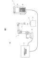
- FIG. 1 is a diagram that illustrates an industrial robot system as an example of a mechanical system according to the present embodiment.
- FIG. 2 is a block diagram showing a configuration of a main part of an example of the portable operating device according to this embodiment.
- FIG. 3 is a flowchart for explaining an example of processing in an embodiment of a memory control program of the portable operating device according to this embodiment.
- FIG. 1 is a diagram that shows an outline of an industrial robot system as an example of a mechanical system according to this embodiment.
- an industrial robot system 100 as an example of a mechanical system according to this embodiment includes an industrial robot (machine) 1, an industrial robot control device (machine control device) 2, and a teaching operation panel (portable operation device) 3.
- a hand unit (end effector) 11A is provided at the tip of the arm 11 of the industrial robot (robot) 1, and this hand unit 11A performs a predetermined process on a workpiece (object) 5 placed on a workbench 4, for example.
- An industrial robot control device (robot control device) 2 controls the robot 1 based on, for example, a pre-installed program (software program) or the like.
- a camera (not shown) for photographing the workpiece 5 etc. may be attached near the hand portion 11A of the arm 11, and an image including the workpiece 5 photographed by this camera may be output to the robot control device 2. Furthermore, it goes without saying that various modifications and variations are possible depending on the type of machine to be used and the processing required.
- the teaching operation panel 3 has a display screen 31 and an operation unit 32, and is connected to the robot control device 2 by wire. This teaching operation panel 3 is used by an operator (instructor) to operate the operation unit 32 while checking the image on the display screen 31, thereby teaching the robot 1 a specified operation using the hand unit 11A via the robot control device 2.
- the teaching pendant 3 is used near a robot 1 installed in an actual factory, for example, and is therefore exposed to electromagnetic noise and the like generated by the robot 1 itself or various surrounding machines.
- the teaching pendant 3 is often used in an environment where various noises, including electromagnetic noise, are present, there is a risk that errors will occur in the data stored in the memory of the teaching pendant 3 due to the effects of electromagnetic noise, etc.
- the teaching operation panel (portable operation device) 3 is connected to the robot control device 2 by a wire, but it may also be configured to be connected to the robot control device 2 wirelessly. Also, it goes without saying that the portable operation device 3 is not limited to a teaching operation panel as shown in FIG. 1, and may be, for example, a tablet (tablet computer) connected to the robot control device 2 by a wire or wirelessly. Furthermore, the portable operation device 3 is not limited to a teaching operation panel that operates robots such as industrial robots and collaborative robots, or CNC machine tools, and can be widely used as a portable operation device that controls various machines.
- FIG. 2 is a block diagram showing the essential components of one embodiment of the portable operating device according to this embodiment, and functionally shows the essential components of the teaching operation panel 3 in the industrial robot system 100 shown in FIG. 1.
- the teaching operation panel 3 has an arithmetic processing device (CPU (Central Processing Unit, MPU (Micro Processing Unit)) 310 and a memory (storage device) 320.
- CPU Central Processing Unit, MPU (Micro Processing Unit)
- memory storage device
- the CPU 310 includes a code assignment unit 311, an encoding area designation unit 312, and a status grasp unit 313.
- the code assignment unit 311 assigns an error correction code to data in the memory 320
- the encoding area designation unit 312 designates an area for storing the data to which the error correction code has been assigned
- the status grasp unit 313 grasps the status of the teaching pendant 3.
- the memory 320 has, for example, N memory sections (a first memory section (memory block) 321, a second memory section 322, ..., an Nth memory section 32N).
- the memory 320 is the main memory (for example, DRAM: Dynamic Random Access Memory) of the CPU 310 in the teaching operation panel 3, and it is possible to control whether or not to activate the error correction code for any of the memory sections 321 to 32N.
- the status grasping unit 313 grasps the status of the application program (program) executed by the CPU 310 of the teaching pendant 3 according to, for example, a control command from the robot control device 2.
- the coding area designation unit 312 designates, for example, an area among the multiple storage units 321 to 32N in which to store the data to which the error correction code has been assigned by the code assignment unit 311, based on the output of the status grasping unit 313.
- the coding area designation unit 312 designates a storage unit for storing data with error correction codes among the multiple (e.g., N) storage units 321, 322, ..., 32N in the memory 320. That is, the coding area designation unit 312 switches the capacity of the area for storing data with error correction codes, which is important data in which errors caused by electromagnetic noise, etc., should not occur, based on the output of the state grasping unit 313.
- the data stored in the area specified by the coding area specification unit 312, i.e., the data to which the error correction code has been added by the code addition unit 311, can be determined, for example, based on the state of the program grasped by the state grasp unit 313.
- the code assignment unit 311 assigns an error correction code to data when the program executed by the CPU 310, as determined by the state determination unit 313, is directly related to the system, and does not assign an error correction code to data when the program is not directly related to the system.
- the coding area designation unit 312 designates an area for storing data with an error correction code added to it when the program executed by the CPU 310, as recognized by the status recognition unit 313, is directly related to the system.
- the coding area designation unit 312 designates an area for storing data without an error correction code added to it when the program executed by the CPU 310, as recognized by the status recognition unit 313, is not directly related to the system.
- the coding area designation unit 312 switches the capacity of the area that stores the data with error correction code among the multiple storage units 321 to 32N based on the state of the program grasped by the state grasp unit 313.
- the code assignment unit 311 can determine whether or not to assign an error correction code by having the status understanding unit 313 understand the program executed by the CPU 310. This understanding of the program by the status understanding unit 313 can also be confirmed, for example, by a control command from the robot control device 2 to the teaching operation panel 3. Furthermore, the determination of whether or not to assign an error correction code is not limited to being determined by whether or not the program executed by the CPU 310 described above is directly related to the system.
- the status grasping unit 313 grasps the operation and usage status of the teaching pendant 3, or various other conditions, and based on the output of the status grasping unit 313, can determine whether the code assignment unit 311 should assign an error correction code.
- the coding area designation unit 312 can designate an area among the multiple storage units 321 to 32N of the memory 320 in which to store the data to which an error correction code has been assigned, based on the output of the status grasping unit 313.
- data to which the code assignment unit 311 assigns an error correction code can be considered to be, for example, important data that is directly related to a system that needs to be protected by applying an error correction code.
- data to which the code assignment unit 311 does not assign an error correction code can be considered to be, for example, data that can tolerate a certain degree of errors and for which it is preferable to avoid an increase in memory usage and a decrease in processing speed due to the application of an error correction code. This makes it possible to suppress an increase in memory usage and a decrease in processing speed while maintaining the reliability of the operation of the teaching pendant 3 (industrial robot system 100).
- FIG. 3 is a flow chart for explaining an example of processing in one embodiment of a memory control program for the portable operating device according to this embodiment, for example, for explaining the processing of a program executed by the arithmetic processing unit 310 of the teaching operation panel 3 shown in FIG. 2.
- step ST1 when one embodiment of the memory control program for the teaching operation panel starts (START), in step ST1, the status grasper 313 grasps the status of the teaching operation panel 3 and determines which areas of the first memory unit to the Nth memory unit (memory blocks 321 to 32N) should have error correction codes added (areas that need to be protected by applying ECC).
- step ST2 the coding area designation unit 312 designates an area to which an error correction code is to be added based on the determination result of the state grasp unit 313. That is, as described above, the coding area designation unit 312 designates an area among the multiple storage units 321 to 32N of the memory 320 in which to store the data to which an error correction code has been added based on the output of the state grasp unit 313.
- the code assignment unit 311 assigns an error correction code to the data in the specified storage unit based on the designation by the coding area designation unit 312. That is, the code assignment unit 311 assigns an error correction code to the data in the area in the memory 320 designated by the coding area designation unit 312 that stores the data to which the error correction code has been assigned.
- the memory control program of the portable operating device may be provided by recording it on a computer-readable non-transitory recording medium or a non-volatile semiconductor memory, or may be provided via a wired or wireless connection.
- Examples of computer-readable non-transitory recording media include optical disks such as CD-ROMs (Compact Disc Read Only Memories) and DVD-ROMs, or hard disk devices.
- Examples of non-volatile semiconductor memory include PROMs (Programmable Read Only Memories) and flash memories. Distribution from a server device may be via a wired or wireless WAN (Wide Area Network), LAN (Local Area Network), or the Internet.
- the portable operating device, mechanical system, and memory control program for the portable operating device make it possible to suppress increases in memory usage and decreases in processing speed while maintaining the reliability of the portable operating device (mechanical system).
- a portable operating device (3) for operating a machine (1) A memory (320) having a plurality of storage units (321 to 32N); a code adding unit (311) that adds an error correction code to the data in the memory (320); A portable operating device comprising: a coding area designation unit (312) that designates an area for storing the data to which the error correction code has been added.
- a state grasping unit (313) for grasping a state of the portable operating device (3) The portable operating device described in Appendix 1, wherein the coding area designation unit (312) designates an area among the multiple memory units (321 to 32N) in which to store data to which the error correction code has been added, based on the output of the status understanding unit (313).
- the portable operating device (3) includes a processor (310) that executes an application program,
- the state grasping unit (313) grasps the state of an application program executed by the arithmetic processing device (310),
- the portable operating device described in Appendix 2 wherein the coding area designation unit (312) switches the capacity of an area among the multiple memory units (321 to 32N) for storing data to which the error correction code has been added, based on the state of the application program grasped by the state grasping unit (313).
- the code assignment unit (311) An error correction code is added to data in the case where the application program recognized by the status recognition unit (313) is directly related to the system, A portable controller according to claim 3, wherein no error correction code is added to data in a case where the application program recognized by the status recognition unit (313) is not directly related to the system.
- the memory (320) is a main memory accessible to the arithmetic processing unit (310), and is a DRAM capable of controlling whether or not to activate the error correction code for any of the storage units (321 to 32N).
- the machine (1) is a robot or a CNC machine tool, The portable operating device according to any one of claims 1 to 6, wherein the portable operating device (3) is a teaching operation panel that teaches an operation to the robot or the CNC machine tool.
- Appendix 7 A portable operating device (3) according to any one of Supplementary Note 1 to Supplementary Note 6; A machine control device (2) connected to the portable operating device (3) via a communication line; A machine system comprising: the machine (1) connected to the machine control device (2) via a communication line and operated by the portable operating device (3) via the machine control device (2).
- the arithmetic processing device (310) further comprises: Grasping the state of the portable operating device (3), A memory control program for a portable operating device as described in Appendix 8, which executes a process to switch the area in which the data to which the error correction code has been added is stored based on the grasped state of the portable operating device (3).
- Industrial robots (machines, robots) 2.
- Industrial robot control device (machine control device, control device) 3
- Teaching operation panel (portable operation device) 4
- Work table 5
- Work 11
- Arm 11A Hand part (end effector) 31
- Display screen 32
- Operation unit 100
- Industrial robot system (machine system, system) 310
- CPU Arimetic processing unit
- Code assignment unit 312
- Encoding area designation unit 313
- Status grasp unit 320 Memory 321 to 32N Storage units (memory blocks)
Abstract
システムの信頼性を維持しつつ、メモリ使用量の増加および処理速度の低下を抑えることができる携帯型操作装置、機械システムおよび携帯型操作装置のメモリ制御プログラムの提供を図る。携帯型操作装置は、機械を操作する可搬式の携帯型操作装置であり、複数の記憶部を有するメモリと、メモリにおけるデータに誤り訂正符号を付与する符号付与部と、誤り訂正符号を付与したデータを格納する領域を指定する符号化領域指定部と、を備える。
Description
本開示は、携帯型操作装置、機械システムおよび携帯型操作装置のメモリ制御プログラムに関する。
近年、ロボットまたはCNC(Computer Numerical Control)工作機械等の機械を操作するために、その機械を制御する機械制御装置に接続された可搬式の携帯型操作装置を使用することがある。ここで、携帯型操作装置の例としては、産業用ロボットに対して動作等を教示する教示操作盤を挙げることができる。この教示操作盤は、例えば、産業用ロボットが実際に設置された工場等において、ワークに対する所定の処理動作を産業用ロボットに行わせるために使用する。
ここで、教示操作盤(携帯型操作装置)は、可搬式とされていて、例えば、産業用ロボット(機械)が設置された工場等で使用されるため、その産業用ロボット自体または周囲の様々な機械から発生する電磁ノイズ等に曝される。すなわち、教示操作盤は、電磁ノイズを始めとする様々なノイズが存在する環境下で使用されることが多いため、教示操作盤に設けられたメモリのデータは、電磁ノイズ等の影響により誤りが生じる虞がある。
そこで、教示操作盤におけるメモリ(メインメモリ)には、例えば、誤り訂正符号(ECC:Error-Correcting Code / Error-Correction Code)が適用されたものが使用されている。ここで、誤り訂正符号とは、例えば、データをメモリに記録する(書き込む)際に、メモリで発生するデータの誤りを受信側(読み出し側)で検出および訂正するために付加される符号である。この誤り訂正符号(ECCデータ)は、例えば、本来のデータから所定のプロトコルに基づいて生成され、その生成されたECCデータを本来のデータに付加してメモリに記録する。
すなわち、ECCデータは、例えば、メモリから読み出されるデータにおける誤り(エラー)を受信側で検出および訂正するために使用される。このECCデータの生成処理としては、例えば、本来のデータを所定の長さに切断し、その切断されたデータに所定のプロトコルを適用して生成する。さらに、本来のデータにECCデータが付加されたデータは、例えば、教示操作盤におけるDRAM(Dynamic Random Access Memory)等で構成されたメインメモリに書き込まれる。
そして、データの読み出し側では、本来のデータに付加されたECCデータを利用して、メモリから読み出したデータにおける誤りの検出および訂正を行う。すなわち、読み出し側では、データの読み出し時に、ECCデータを本来のデータから分離し、予め定められたプロトコルを適用して本来のデータに誤りがないか確認する。さらに、読み出し側において、誤りが検出された場合には、ECCデータに基づいて正しいデータへの復元を行う。
ここで、誤り訂正符号(ECC)としては様々な方式が提案されているが、全ての誤りを完全に検出および訂正できるものはなく、所定の長さ当たり何ビットまでの誤りを検出または訂正できるかが各方式により決まっている。一般的に、誤り訂正符号を長くすれば、検出/訂正できる誤り(ビット数)も増えるが、誤りを検出/訂正するためのに使用するメモリ容量や計算量も増加することになる。
すなわち、誤り訂正符号を適用して検出/訂正を行うビット数を多くすると、それに伴って誤り訂正符号のデータ量や処理時間も長くなる。そのため、誤り訂正符号の適用は、検出/訂正を行うビット数の要求と、利用可能なメモリ容量や帯域幅等を勘案して適切なものが選ばれる。なお、誤り訂正符号としては、例えば、ハミング符号や水平垂直パリティ符号、リードソロモン符号およびBCH符号といった様々なものが使用されている。
従来、誤り訂正符号を付与する機能を有する教示操作盤としては、様々な提案がなされている。
前述のように、産業用ロボットが設置された工場において、可搬式の教示操作盤は、通常、産業用ロボットの近傍で使用されるため、産業用ロボット自体または周囲の様々な機械から発生する電磁ノイズ等に曝される。そのため、教示操作盤のメモリに格納されたデータに誤りが生じる虞があり、誤り訂正符号を適用することが行われている。
しかしながら、誤り訂正符号を適用すると、誤り訂正符号用のデータ(ECCデータ)を追加する必要が生じ、さらに、誤り訂正(検出および訂正)を行うための処理も必要になる。すなわち、教示操作盤において、誤り訂正符号を適用すると、教示操作盤におけるメモリ使用量の増加、並びに、処理速度の低下を招くことになる。
ここで、教示操作盤は、ワークに対する所定の動作を産業用ロボットに教示するものに限定されず、協働ロボット等の各種ロボットやCNC工作機械といった様々な機械を操作する可搬式の携帯型操作装置でもよい。すなわち、本明細書における携帯型操作装置は、教示操作盤を含む様々な機械を操作する可搬式(携帯型)の装置である。
このように、携帯型操作装置、機械システムおよび携帯型操作装置のメモリ制御プログラムにおいては、信頼性を維持しつつ、メモリ使用量の増加および処理速度の低下を抑えることが望まれている。
本開示に係る一実施形態によれば、機械を操作する可搬式の携帯型操作装置であって、複数の記憶部を有するメモリと、符号付与部と、符号化領域指定部と、を備える携帯型操作装置が提供される。符号付与部は、メモリにおけるデータに誤り訂正符号を付与し、符号化領域指定部は、誤り訂正符号を付与したデータを格納する領域を指定する。
本発明の目的および効果は、特に請求項において指摘される構成要素および組み合わせを用いることによって認識され且つ得られるであろう。前述の一般的な説明および後述の詳細な説明の両方は、例示的および説明的なものであり、請求の範囲に記載されている本発明を制限するものではない。
以下、本実施形態に係る携帯型操作装置、機械システムおよび携帯型操作装置のメモリ制御プログラムの実施例を、添付図面を参照して詳述する。各図面において、同一または類似の構成要素には同一または類似の符号が付与されている。また、以下に記載する実施形態は、特許請求の範囲に記載される発明の技術的範囲および用語の意義を限定するものではない。
図1は、本実施形態に係る機械システムの一例としての産業用ロボットシステムを概略的に示す図である。図1に示されるように、本実施形態に係る機械システムの一例としての産業用ロボットシステム100は、産業用ロボット(機械)1、産業用ロボット制御装置(機械制御装置)2、および、教示操作盤(携帯型操作装置)3を備える。
産業用ロボット(ロボット)1のアーム11の先端には、ハンド部(エンドエフェクタ)11Aが設けられ、このハンド部11Aにより、例えば、作業台4に載置されたワーク(対象物)5に対する所定の処理を行う。産業用ロボット制御装置(ロボット制御装置)2は、例えば、予めインストールされたプログラム(ソフトウェアプログラム)等に基づいて、ロボット1を制御する。
ここで、アーム11におけるハンド部11Aの近傍に、ワーク5等を撮影するためのカメラ(図示しない)を取り付け、このカメラにより撮影されたワーク5を含む画像をロボット制御装置2に出力するように構成してもよい。さらに、適用する機械の種類や要求する処理に応じて、様々な変更および変形が可能なのは言うまでもない。
教示操作盤3は、表示画面31および操作部32を備え、有線によりロボット制御装置2に接続されている。この教示操作盤3は、作業者(教示者)が表示画面31の画像を確認しながら操作部32を操作することで、ロボット1に対してハンド部11Aを使用した所定の動作をロボット制御装置2を介して教示するために使用される。
ここで、教示操作盤3は、例えば、実際の工場に設置されたロボット1の近くで使用されるため、そのロボット1自体または周囲の様々な機械から発生する電磁ノイズ等に曝されることになる。すなわち、教示操作盤3は、電磁ノイズを始めとして様々なノイズが存在する環境下で使用されることが多いため、教示操作盤3に設けられたメモリのデータは、電磁ノイズ等の影響により誤り(エラー)が生じる虞がある。
なお、図1において、教示操作盤(携帯型操作装置)3は、有線によりロボット制御装置2に接続されているが、無線によりロボット制御装置2に接続するように構成してもよい。また、携帯型操作装置3は、図1に示すような教示操作盤に限定されるものではなく、例えば、有線または無線でロボット制御装置2に接続されたタブレット(タブレットコンピュータ)等であってもよいのは言うまでもない。さらに、携帯型操作装置3は、産業用ロボットや協働ロボット等のロボット、或いは、CNC工作機械等を操作する教示操作盤に限定されず、様々な機械を制御する可搬式の操作装置として、幅広く適用することができる。
図2は、本実施形態に係る携帯型操作装置の一実施例における要部構成を示すブロック図であり、図1に示す産業用ロボットシステム100における教示操作盤3の要部を機能的に示すものである。図2に示されるように、教示操作盤3は、演算処理装置(CPU(Central Processing Unit、MPU(Micro Processing Unit))310およびメモリ(記憶装置)320を備える。
CPU310は、符号付与部311、符号化領域指定部312および状態把握部313を備える。符号付与部311は、メモリ320におけるデータに誤り訂正符号を付与し、符号化領域指定部312は、誤り訂正符号を付与したデータを格納する領域を指定し、そして、状態把握部313は、教示操作盤3の状態を把握する。
メモリ320は、例えば、N個の記憶部(第1記憶部(メモリブロック)321,第2記憶部322,…,第N記憶部32N)を有する。ここで、メモリ320は、教示操作盤3におけるCPU310のメインメモリ(例えば、DRAM:Dynamic Random Access Memory)であり、任意の記憶部321~32Nに対して誤り訂正符号を機能させるか否かの制御が可能となっている。
状態把握部313は、例えば、ロボット制御装置2からの制御指令に従って教示操作盤3のCPU310が実行するアプリケーションプログラム(プログラム)の状態を把握する。符号化領域指定部312は、例えば、状態把握部313の出力に基づいて、複数の記憶部321~32Nのうち、符号付与部311により誤り訂正符号が付与されたデータを格納する領域を指定する。
符号化領域指定部312は、メモリ320が有する複数(例えば、N個)の記憶部321,322,…,32Nにおいて、誤り訂正符号を付与したデータを格納する記憶部を指定する。すなわち、符号化領域指定部312は、状態把握部313の出力に基づいて、例えば、電磁ノイズ等により誤りが生じては困る重要なデータである誤り訂正符号を付与したデータを格納する領域の容量を切り替える。
ここで、符号化領域指定部312により指定された領域に格納されるデータ、すなわち、符号付与部311により誤り訂正符号が付与されたデータは、例えば、状態把握部313が把握するプログラムの状態により決めることができる。
具体的に、例えば、CPU310が実行するプログラムが、産業用ロボット1を操作するといった産業用ロボットシステム100に直接関係する場合には、誤り訂正符号を付与したデータを符号化領域指定部312が指定したメモリ320の領域に書き込む。一方、例えば、CPU310が実行するプログラムが、教示操作盤3の表示画面31のスクリーンショット撮影やログの採取といった産業用ロボットシステム100に直接関係しない場合には、誤り訂正符号を付与しないデータをメモリ320に書き込む。
すなわち、符号付与部311は、状態把握部313が把握したCPU310が実行するプログラムがシステムに直接関係する場合のデータに対しては誤り訂正符号を付与し、システムに直接関係しない場合のデータに対しては誤り訂正符号を付与しない。
換言すると、符号化領域指定部312は、状態把握部313が把握したCPU310が実行するプログラムがシステムに直接関係する場合のデータに対しては誤り訂正符号を付与したデータを格納する領域を指定する。一方、符号化領域指定部312は、状態把握部313が把握したCPU310が実行するプログラムがシステムに直接関係しない場合のデータに対しては誤り訂正符号を付与しないデータを格納する領域を指定する。
このように、符号化領域指定部312は、状態把握部313が把握したプログラムの状態に基づいて、複数の記憶部321~32Nのうち、誤り訂正符号を付与したデータを格納する領域の容量を切り替える。
ここで、符号付与部311が誤り訂正符号を付与するか否かの判別は、CPU310が実行するプログラムを状態把握部313が把握して決めることができる。この状態把握部313によるプログラムの把握は、例えば、ロボット制御装置2から教示操作盤3に対する制御指令により確認することもできる。さらに、誤り訂正符号を付与するか否かの判別は、上述したCPU310が実行するプログラムがシステムに直接関係するかどうかにより決定するのに限定されるものではない。
すなわち、状態把握部313は、教示操作盤3の動作や使用状況、或いは、他の様々な状態を把握し、その状態把握部313の出力に基づいて、符号付与部311が誤り訂正符号を付与するか否かのデータを判別することができる。若しくは、符号化領域指定部312は、状態把握部313の出力に基づいて、メモリ320の複数の記憶部321~32Nのうち、誤り訂正符号を付与したデータを格納する領域を指定することができる。
ここで、符号付与部311が誤り訂正符号を付与するデータとしては、例えば、誤り訂正符号を適用して保護する必要があるシステムに直接関係するといった重要なデータと捉えることができる。一方、符号付与部311が誤り訂正符号を付与しないデータとしては、例えば、或る程度の誤りを許容することができ、誤り訂正符号の適用によるメモリ使用量の増加および処理速度の低下を避ける方が好ましいデータと捉えることができる。これにより、教示操作盤3(産業用ロボットシステム100)の動作の信頼性を維持しつつ、メモリ使用量の増加および処理速度の低下を抑えることが可能になる。
図3は、本実施形態に係る携帯型操作装置のメモリ制御プログラムの一実施例における処理の一例を説明するためのフローチャートであり、例えば、図2に示す教示操作盤3の演算処理装置310により実行されるプログラムの処理を説明するためのものである。
図3に示されるように、教示操作盤のメモリ制御プログラムの一実施例が開始(START)すると、ステップST1において、状態把握部313が教示操作盤3の状態を把握し、第1記憶部~第N記憶部((メモリブロック321~32N)のうち、誤り訂正符号を付与する領域(ECCを適用して保護する必要のある領域)を判定する。
次に、ステップST2に進んで、状態把握部313の判定結果に基づいて、符号化領域指定部312が、誤り訂正符号を付与する領域を指定する。すなわち、前述したように、符号化領域指定部312は、状態把握部313の出力に基づいて、メモリ320の複数の記憶部321~32Nのうち、誤り訂正符号を付与したデータを格納する領域を指定する。
さらに、ステップST3に進んで、符号化領域指定部312の指定に基づいて、符号付与部311が、指定された記憶部のデータに誤り訂正符号を付与する。すなわち、符号付与部311は、符号化領域指定部312が指定したメモリ320における誤り訂正符号を付与したデータを格納する領域に対して、そのデータに誤り訂正符号を付与する。
ここで、上述した本実施形態に係る携帯型操作装置のメモリ制御プログラムは、コンピュータ読み取り可能な非一時的記録媒体や不揮発性半導体メモリに記録して提供してもよく、また、有線または無線を介して提供してもよい。ここで、コンピュータ読み取り可能な非一時的記録媒体としては、例えば、CD-ROM(Compact Disc Read Only Memory)やDVD-ROM等の光ディスク、或いは、ハードディスク装置等が考えられる。また、不揮発性半導体メモリとしては、PROM(Programmable Read Only Memory)やフラッシュメモリ(Flash Memory)等が考えられる。さらに、サーバ装置からの配信としては、有線または無線によるWAN(Wide Area Network)、LAN(Local Area Network)またはインターネット等を介した提供が考えられる。
以上、詳述したように、本実施形態に係る携帯型操作装置、機械システムおよび携帯型操作装置のメモリ制御プログラムによれば、携帯型操作装置(機械システム)の信頼性を維持しつつ、メモリ使用量の増加および処理速度の低下を抑えることが可能になる。
本開示について詳述したが、本開示は上述した個々の実施形態に限定されるものではない。これらの実施形態は、本開示の要旨を逸脱しない範囲で、または、特許請求の範囲に記載された内容とその均等物から導き出される本開示の趣旨を逸脱しない範囲で、種々の追加、置き換え、変更、部分的削除等が可能である。また、これらの実施形態は、組み合わせて実施することもできる。例えば、上述した実施形態において、各動作の順序や各処理の順序は、一例として示したものであり、これらに限定されるものではない。また、上述した実施形態の説明に数値または数式が用いられている場合も同様である。
上記実施形態および変形例に関し、さらに、以下の付記を開示する。
[付記1]
機械(1)を操作する可搬式の携帯型操作装置(3)であって、
複数の記憶部(321~32N)を有するメモリ(320)と、
前記メモリ(320)におけるデータに誤り訂正符号を付与する符号付与部(311)と、
前記誤り訂正符号を付与したデータを格納する領域を指定する符号化領域指定部(312)と、を備える、携帯型操作装置。
[付記2]
さらに、
前記携帯型操作装置(3)の状態を把握する状態把握部(313)を備え、
前記符号化領域指定部(312)は、前記状態把握部(313)の出力に基づいて、前記複数の記憶部(321~32N)のうち、前記誤り訂正符号を付与したデータを格納する領域を指定する、付記1に記載の携帯型操作装置。
[付記3]
前記携帯型操作装置(3)は、アプリケーションプログラムを実行する演算処理装置(310)を備え、
前記状態把握部(313)は、前記演算処理装置(310)が実行するアプリケーションプログラムの状態を把握し、
前記符号化領域指定部(312)は、前記状態把握部(313)が把握した前記アプリケーションプログラムの状態に基づいて、前記複数の記憶部(321~32N)のうち、前記誤り訂正符号を付与したデータを格納する領域の容量を切り替える、付記2に記載の携帯型操作装置。
[付記4]
前記符号付与部(311)は、
前記状態把握部(313)が把握した前記アプリケーションプログラムがシステムに直接関係する場合のデータに対しては誤り訂正符号を付与し、
前記状態把握部(313)が把握した前記アプリケーションプログラムがシステムに直接関係しない場合のデータに対しては誤り訂正符号を付与しない、付記3に記載の携帯型操作装置。
[付記5]
前記メモリ(320)は、前記演算処理装置(310)がアクセス可能なメインメモリであり、任意の前記記憶部(321~32N)に対して前記誤り訂正符号を機能させるか否かの制御が可能なDRAMである、付記3または付記4に記載の携帯型操作装置。
[付記6]
前記機械(1)は、ロボットまたはCNC工作機械であり、
前記携帯型操作装置(3)は、前記ロボットまたは前記CNC工作機械に動作を教示する教示操作盤である、付記1乃至付記6のいずれか1項に記載の携帯型操作装置。
[付記7]
付記1乃至付記6のいずれか1項に記載の携帯型操作装置(3)と、
通信回線を介して前記携帯型操作装置(3)に接続された機械制御装置(2)と、
通信回線を介して前記機械制御装置(2)に接続され、前記機械制御装置(2)を介して前記携帯型操作装置(3)により操作される前記機械(1)と、を備える、機械システム。
[付記8]
演算処理装置(310)と、前記演算処理装置(310)がアクセスする複数の記憶部(321~32N)を有するメモリ(320)と、を備えた携帯型操作装置(3)のメモリ制御プログラムであって、
前記演算処理装置(310)に、
前記メモリ(320)におけるデータに誤り訂正符号を付与し、
前記誤り訂正符号を付与したデータを格納する領域を指定する、処理を実行させる携帯型操作装置のメモリ制御プログラム。
[付記9]
前記演算処理装置(310)に、さらに、
前記携帯型操作装置(3)の状態を把握し、
把握した前記携帯型操作装置(3)の状態に基づいて、前記誤り訂正符号を付与したデータを格納する領域を切り替える、処理を実行させる付記8に記載の携帯型操作装置のメモリ制御プログラム。
1 産業用ロボット(機械、ロボット)
2 産業用ロボット制御装置(機械制御装置、制御装置)
3 教示操作盤(携帯型操作装置)
4 作業台
5 ワーク(対象物)
11 アーム
11A ハンド部(エンドエフェクタ)
31 表示画面
32 操作部
100 産業用ロボットシステム(機械システム、システム)
310 CPU(演算処理装置)
311 符号付与部
312 符号化領域指定部
313 状態把握部
320 メモリ
321~32N 記憶部(メモリブロック)
2 産業用ロボット制御装置(機械制御装置、制御装置)
3 教示操作盤(携帯型操作装置)
4 作業台
5 ワーク(対象物)
11 アーム
11A ハンド部(エンドエフェクタ)
31 表示画面
32 操作部
100 産業用ロボットシステム(機械システム、システム)
310 CPU(演算処理装置)
311 符号付与部
312 符号化領域指定部
313 状態把握部
320 メモリ
321~32N 記憶部(メモリブロック)
Claims (9)
- 機械を操作する可搬式の携帯型操作装置であって、
複数の記憶部を有するメモリと、
前記メモリにおけるデータに誤り訂正符号を付与する符号付与部と、
前記誤り訂正符号を付与したデータを格納する領域を指定する符号化領域指定部と、を備える、携帯型操作装置。 - さらに、
前記携帯型操作装置の状態を把握する状態把握部を備え、
前記符号化領域指定部は、前記状態把握部の出力に基づいて、前記複数の記憶部のうち、前記誤り訂正符号を付与したデータを格納する領域を指定する、請求項1に記載の携帯型操作装置。 - 前記携帯型操作装置は、アプリケーションプログラムを実行する演算処理装置を備え、
前記状態把握部は、前記演算処理装置が実行するアプリケーションプログラムの状態を把握し、
前記符号化領域指定部は、前記状態把握部が把握した前記アプリケーションプログラムの状態に基づいて、前記複数の記憶部のうち、前記誤り訂正符号を付与したデータを格納する領域の容量を切り替える、請求項2に記載の携帯型操作装置。 - 前記符号付与部は、
前記状態把握部が把握した前記アプリケーションプログラムがシステムに直接関係する場合のデータに対しては誤り訂正符号を付与し、
前記状態把握部が把握した前記アプリケーションプログラムがシステムに直接関係しない場合のデータに対しては誤り訂正符号を付与しない、請求項3に記載の携帯型操作装置。 - 前記メモリは、前記演算処理装置がアクセス可能なメインメモリであり、任意の前記記憶部に対して前記誤り訂正符号を機能させるか否かの制御が可能なDRAMである、請求項3または請求項4に記載の携帯型操作装置。
- 前記機械は、ロボットまたはCNC工作機械であり、
前記携帯型操作装置は、前記ロボットまたは前記CNC工作機械に動作を教示する教示操作盤である、請求項1乃至請求項6のいずれか1項に記載の携帯型操作装置。 - 請求項1乃至請求項6のいずれか1項に記載の携帯型操作装置と、
通信回線を介して前記携帯型操作装置に接続された機械制御装置と、
通信回線を介して前記機械制御装置に接続され、前記機械制御装置を介して前記携帯型操作装置により操作される前記機械と、を備える、機械システム。 - 演算処理装置と、前記演算処理装置がアクセスする複数の記憶部を有するメモリと、を備えた携帯型操作装置のメモリ制御プログラムであって、
前記演算処理装置に、
前記メモリにおけるデータに誤り訂正符号を付与し、
前記誤り訂正符号を付与したデータを格納する領域を指定する、処理を実行させる携帯型操作装置のメモリ制御プログラム。 - 前記演算処理装置に、さらに、
前記携帯型操作装置の状態を把握し、
把握した前記携帯型操作装置の状態に基づいて、前記誤り訂正符号を付与したデータを格納する領域を切り替える、処理を実行させる請求項8に記載の携帯型操作装置のメモリ制御プログラム。
Priority Applications (1)
| Application Number | Priority Date | Filing Date | Title |
|---|---|---|---|
| PCT/JP2022/036517 WO2024069880A1 (ja) | 2022-09-29 | 2022-09-29 | 携帯型操作装置、機械システムおよび携帯型操作装置のメモリ制御プログラム |
Applications Claiming Priority (1)
| Application Number | Priority Date | Filing Date | Title |
|---|---|---|---|
| PCT/JP2022/036517 WO2024069880A1 (ja) | 2022-09-29 | 2022-09-29 | 携帯型操作装置、機械システムおよび携帯型操作装置のメモリ制御プログラム |
Publications (1)
| Publication Number | Publication Date |
|---|---|
| WO2024069880A1 true WO2024069880A1 (ja) | 2024-04-04 |
Family
ID=90476863
Family Applications (1)
| Application Number | Title | Priority Date | Filing Date |
|---|---|---|---|
| PCT/JP2022/036517 WO2024069880A1 (ja) | 2022-09-29 | 2022-09-29 | 携帯型操作装置、機械システムおよび携帯型操作装置のメモリ制御プログラム |
Country Status (1)
| Country | Link |
|---|---|
| WO (1) | WO2024069880A1 (ja) |
Citations (5)
| Publication number | Priority date | Publication date | Assignee | Title |
|---|---|---|---|---|
| JPS63295150A (ja) * | 1987-05-08 | 1988-12-01 | ケルベル・アクチエンゲゼルシヤフト | 工作機械 |
| JP2003316663A (ja) * | 2002-04-22 | 2003-11-07 | Oki Electric Ind Co Ltd | データ処理と誤り検出訂正の方法及びそのシステム並びにプログラム |
| JP2008139908A (ja) * | 2006-11-29 | 2008-06-19 | Matsushita Electric Ind Co Ltd | メモリ制御装置、コンピュータシステム及びデータ再生記録装置 |
| JP2018097723A (ja) * | 2016-12-15 | 2018-06-21 | ファナック株式会社 | Nandフラッシュメモリの寿命を予測する機械学習装置、寿命予測装置、数値制御装置、生産システム、及び機械学習方法 |
| JP2020078865A (ja) * | 2018-11-09 | 2020-05-28 | リープヘル−フェアツァーンテヒニク ゲゼルシャフト ミット ベシュレンクテル ハフツング | 操作盤 |
-
2022
- 2022-09-29 WO PCT/JP2022/036517 patent/WO2024069880A1/ja unknown
Patent Citations (5)
| Publication number | Priority date | Publication date | Assignee | Title |
|---|---|---|---|---|
| JPS63295150A (ja) * | 1987-05-08 | 1988-12-01 | ケルベル・アクチエンゲゼルシヤフト | 工作機械 |
| JP2003316663A (ja) * | 2002-04-22 | 2003-11-07 | Oki Electric Ind Co Ltd | データ処理と誤り検出訂正の方法及びそのシステム並びにプログラム |
| JP2008139908A (ja) * | 2006-11-29 | 2008-06-19 | Matsushita Electric Ind Co Ltd | メモリ制御装置、コンピュータシステム及びデータ再生記録装置 |
| JP2018097723A (ja) * | 2016-12-15 | 2018-06-21 | ファナック株式会社 | Nandフラッシュメモリの寿命を予測する機械学習装置、寿命予測装置、数値制御装置、生産システム、及び機械学習方法 |
| JP2020078865A (ja) * | 2018-11-09 | 2020-05-28 | リープヘル−フェアツァーンテヒニク ゲゼルシャフト ミット ベシュレンクテル ハフツング | 操作盤 |
Similar Documents
| Publication | Publication Date | Title |
|---|---|---|
| US8707134B2 (en) | Data storage apparatus and apparatus and method for controlling nonvolatile memories | |
| JP5220183B2 (ja) | 数値制御装置および当該数値制御装置の制御方法 | |
| US11561527B2 (en) | NC program conversion process method and processing treatment system | |
| JP2013542541A (ja) | データのブロックを不揮発性メモリデバイスに冗長方式で格納するためのメモリコントローラ及びメモリシステム | |
| WO2024069880A1 (ja) | 携帯型操作装置、機械システムおよび携帯型操作装置のメモリ制御プログラム | |
| US9928137B2 (en) | Data storage device and error correction method | |
| JP5886656B2 (ja) | 数値制御装置 | |
| JP6477553B2 (ja) | プログラム開発支援装置、プログラム開発支援プログラムおよびプログラム開発支援方法 | |
| TW202414133A (zh) | 攜帶型操作裝置、機械系統及攜帶型操作裝置之記憶體控制程式 | |
| JP4357305B2 (ja) | 外部記憶装置 | |
| JP6052288B2 (ja) | ディスクアレイ制御装置、ディスクアレイ制御方法及びディスクアレイ制御プログラム | |
| JP7112375B2 (ja) | Ncプログラム生成システム及びncプログラム生成方法 | |
| JP7359543B2 (ja) | 機械の制御装置 | |
| JP2020075304A (ja) | 減速機システム、駆動ユニットへの指令値の補正方法、補正データの生成方法、及び減速機システムの製造方法 | |
| JP5087970B2 (ja) | 情報処理装置および情報処理方法 | |
| JP6472587B1 (ja) | 数値制御装置および情報処理装置 | |
| KR20200144038A (ko) | 산업용 적재로봇 제어 시스템 | |
| JP2021152900A5 (ja) | ||
| JP2021099575A (ja) | 制御装置、及び制御方法 | |
| JP2009083000A (ja) | ロボットの動作チェック機能を備えたロボット制御装置及び制御方法 | |
| TW201606785A (zh) | 記憶體控制器 | |
| WO2019207679A1 (ja) | モニタ支援装置、プログラマブルロジックコントローラ、モニタ支援方法およびモニタ支援プログラム | |
| WO2015163219A1 (ja) | 制御装置 | |
| JP2020136867A (ja) | 制御装置、プログラム、及び無線通信機器 | |
| US11531551B2 (en) | PLC device that transmits an instruction to a control device |