WO2024069859A1 - 超音波ヘッド装置、超音波治療システム、及び超音波治療システムの制御方法 - Google Patents
超音波ヘッド装置、超音波治療システム、及び超音波治療システムの制御方法 Download PDFInfo
- Publication number
- WO2024069859A1 WO2024069859A1 PCT/JP2022/036464 JP2022036464W WO2024069859A1 WO 2024069859 A1 WO2024069859 A1 WO 2024069859A1 JP 2022036464 W JP2022036464 W JP 2022036464W WO 2024069859 A1 WO2024069859 A1 WO 2024069859A1
- Authority
- WO
- WIPO (PCT)
- Prior art keywords
- cylindrical portion
- ultrasonic
- head device
- water bag
- central axis
- Prior art date
- Legal status (The legal status is an assumption and is not a legal conclusion. Google has not performed a legal analysis and makes no representation as to the accuracy of the status listed.)
- Ceased
Links
Images



Classifications
-
- A—HUMAN NECESSITIES
- A61—MEDICAL OR VETERINARY SCIENCE; HYGIENE
- A61B—DIAGNOSIS; SURGERY; IDENTIFICATION
- A61B17/00—Surgical instruments, devices or methods
- A61B17/22—Implements for squeezing-off ulcers or the like on inner organs of the body; Implements for scraping-out cavities of body organs, e.g. bones; for invasive removal or destruction of calculus using mechanical vibrations; for removing obstructions in blood vessels, not otherwise provided for
- A61B17/225—Implements for squeezing-off ulcers or the like on inner organs of the body; Implements for scraping-out cavities of body organs, e.g. bones; for invasive removal or destruction of calculus using mechanical vibrations; for removing obstructions in blood vessels, not otherwise provided for for extracorporeal shock wave lithotripsy [ESWL], e.g. by using ultrasonic waves
-
- A—HUMAN NECESSITIES
- A61—MEDICAL OR VETERINARY SCIENCE; HYGIENE
- A61N—ELECTROTHERAPY; MAGNETOTHERAPY; RADIATION THERAPY; ULTRASOUND THERAPY
- A61N7/00—Ultrasound therapy
- A61N7/02—Localised ultrasound hyperthermia
-
- A—HUMAN NECESSITIES
- A61—MEDICAL OR VETERINARY SCIENCE; HYGIENE
- A61B—DIAGNOSIS; SURGERY; IDENTIFICATION
- A61B17/00—Surgical instruments, devices or methods
- A61B17/22—Implements for squeezing-off ulcers or the like on inner organs of the body; Implements for scraping-out cavities of body organs, e.g. bones; for invasive removal or destruction of calculus using mechanical vibrations; for removing obstructions in blood vessels, not otherwise provided for
- A61B17/225—Implements for squeezing-off ulcers or the like on inner organs of the body; Implements for scraping-out cavities of body organs, e.g. bones; for invasive removal or destruction of calculus using mechanical vibrations; for removing obstructions in blood vessels, not otherwise provided for for extracorporeal shock wave lithotripsy [ESWL], e.g. by using ultrasonic waves
- A61B17/2251—Implements for squeezing-off ulcers or the like on inner organs of the body; Implements for scraping-out cavities of body organs, e.g. bones; for invasive removal or destruction of calculus using mechanical vibrations; for removing obstructions in blood vessels, not otherwise provided for for extracorporeal shock wave lithotripsy [ESWL], e.g. by using ultrasonic waves characterised by coupling elements between the apparatus, e.g. shock wave apparatus or locating means, and the patient, e.g. details of bags, pressure control of bag on patient
-
- A—HUMAN NECESSITIES
- A61—MEDICAL OR VETERINARY SCIENCE; HYGIENE
- A61B—DIAGNOSIS; SURGERY; IDENTIFICATION
- A61B17/00—Surgical instruments, devices or methods
- A61B17/22—Implements for squeezing-off ulcers or the like on inner organs of the body; Implements for scraping-out cavities of body organs, e.g. bones; for invasive removal or destruction of calculus using mechanical vibrations; for removing obstructions in blood vessels, not otherwise provided for
- A61B17/225—Implements for squeezing-off ulcers or the like on inner organs of the body; Implements for scraping-out cavities of body organs, e.g. bones; for invasive removal or destruction of calculus using mechanical vibrations; for removing obstructions in blood vessels, not otherwise provided for for extracorporeal shock wave lithotripsy [ESWL], e.g. by using ultrasonic waves
- A61B17/2255—Means for positioning patient, shock wave apparatus or locating means, e.g. mechanical aspects, patient beds, support arms or aiming means
-
- A—HUMAN NECESSITIES
- A61—MEDICAL OR VETERINARY SCIENCE; HYGIENE
- A61B—DIAGNOSIS; SURGERY; IDENTIFICATION
- A61B8/00—Diagnosis using ultrasonic, sonic or infrasonic waves
- A61B8/08—Clinical applications
- A61B8/0833—Clinical applications involving detecting or locating foreign bodies or organic structures
- A61B8/085—Clinical applications involving detecting or locating foreign bodies or organic structures for locating body or organic structures, e.g. tumours, calculi, blood vessels, nodules
-
- A—HUMAN NECESSITIES
- A61—MEDICAL OR VETERINARY SCIENCE; HYGIENE
- A61B—DIAGNOSIS; SURGERY; IDENTIFICATION
- A61B8/00—Diagnosis using ultrasonic, sonic or infrasonic waves
- A61B8/42—Details of probe positioning or probe attachment to the patient
- A61B8/4209—Details of probe positioning or probe attachment to the patient by using holders, e.g. positioning frames
-
- A—HUMAN NECESSITIES
- A61—MEDICAL OR VETERINARY SCIENCE; HYGIENE
- A61B—DIAGNOSIS; SURGERY; IDENTIFICATION
- A61B8/00—Diagnosis using ultrasonic, sonic or infrasonic waves
- A61B8/42—Details of probe positioning or probe attachment to the patient
- A61B8/4272—Details of probe positioning or probe attachment to the patient involving the acoustic interface between the transducer and the tissue
- A61B8/4281—Details of probe positioning or probe attachment to the patient involving the acoustic interface between the transducer and the tissue characterised by sound-transmitting media or devices for coupling the transducer to the tissue
-
- A—HUMAN NECESSITIES
- A61—MEDICAL OR VETERINARY SCIENCE; HYGIENE
- A61B—DIAGNOSIS; SURGERY; IDENTIFICATION
- A61B8/00—Diagnosis using ultrasonic, sonic or infrasonic waves
- A61B8/44—Constructional features of the ultrasonic, sonic or infrasonic diagnostic device
- A61B8/4444—Constructional features of the ultrasonic, sonic or infrasonic diagnostic device related to the probe
-
- A—HUMAN NECESSITIES
- A61—MEDICAL OR VETERINARY SCIENCE; HYGIENE
- A61B—DIAGNOSIS; SURGERY; IDENTIFICATION
- A61B17/00—Surgical instruments, devices or methods
- A61B2017/00477—Coupling
-
- A—HUMAN NECESSITIES
- A61—MEDICAL OR VETERINARY SCIENCE; HYGIENE
- A61B—DIAGNOSIS; SURGERY; IDENTIFICATION
- A61B17/00—Surgical instruments, devices or methods
- A61B17/22—Implements for squeezing-off ulcers or the like on inner organs of the body; Implements for scraping-out cavities of body organs, e.g. bones; for invasive removal or destruction of calculus using mechanical vibrations; for removing obstructions in blood vessels, not otherwise provided for
- A61B17/225—Implements for squeezing-off ulcers or the like on inner organs of the body; Implements for scraping-out cavities of body organs, e.g. bones; for invasive removal or destruction of calculus using mechanical vibrations; for removing obstructions in blood vessels, not otherwise provided for for extracorporeal shock wave lithotripsy [ESWL], e.g. by using ultrasonic waves
- A61B17/2251—Implements for squeezing-off ulcers or the like on inner organs of the body; Implements for scraping-out cavities of body organs, e.g. bones; for invasive removal or destruction of calculus using mechanical vibrations; for removing obstructions in blood vessels, not otherwise provided for for extracorporeal shock wave lithotripsy [ESWL], e.g. by using ultrasonic waves characterised by coupling elements between the apparatus, e.g. shock wave apparatus or locating means, and the patient, e.g. details of bags, pressure control of bag on patient
- A61B2017/2253—Implements for squeezing-off ulcers or the like on inner organs of the body; Implements for scraping-out cavities of body organs, e.g. bones; for invasive removal or destruction of calculus using mechanical vibrations; for removing obstructions in blood vessels, not otherwise provided for for extracorporeal shock wave lithotripsy [ESWL], e.g. by using ultrasonic waves characterised by coupling elements between the apparatus, e.g. shock wave apparatus or locating means, and the patient, e.g. details of bags, pressure control of bag on patient using a coupling gel or liquid
-
- A—HUMAN NECESSITIES
- A61—MEDICAL OR VETERINARY SCIENCE; HYGIENE
- A61B—DIAGNOSIS; SURGERY; IDENTIFICATION
- A61B18/00—Surgical instruments, devices or methods for transferring non-mechanical forms of energy to or from the body
- A61B2018/00571—Surgical instruments, devices or methods for transferring non-mechanical forms of energy to or from the body for achieving a particular surgical effect
- A61B2018/00595—Cauterization
-
- A—HUMAN NECESSITIES
- A61—MEDICAL OR VETERINARY SCIENCE; HYGIENE
- A61B—DIAGNOSIS; SURGERY; IDENTIFICATION
- A61B2217/00—General characteristics of surgical instruments
- A61B2217/002—Auxiliary appliance
-
- A—HUMAN NECESSITIES
- A61—MEDICAL OR VETERINARY SCIENCE; HYGIENE
- A61B—DIAGNOSIS; SURGERY; IDENTIFICATION
- A61B34/00—Computer-aided surgery; Manipulators or robots specially adapted for use in surgery
- A61B34/30—Surgical robots
-
- A—HUMAN NECESSITIES
- A61—MEDICAL OR VETERINARY SCIENCE; HYGIENE
- A61N—ELECTROTHERAPY; MAGNETOTHERAPY; RADIATION THERAPY; ULTRASOUND THERAPY
- A61N7/00—Ultrasound therapy
- A61N2007/0078—Ultrasound therapy with multiple treatment transducers
-
- A—HUMAN NECESSITIES
- A61—MEDICAL OR VETERINARY SCIENCE; HYGIENE
- A61N—ELECTROTHERAPY; MAGNETOTHERAPY; RADIATION THERAPY; ULTRASOUND THERAPY
- A61N7/00—Ultrasound therapy
- A61N2007/0082—Scanning transducers
-
- A—HUMAN NECESSITIES
- A61—MEDICAL OR VETERINARY SCIENCE; HYGIENE
- A61N—ELECTROTHERAPY; MAGNETOTHERAPY; RADIATION THERAPY; ULTRASOUND THERAPY
- A61N7/00—Ultrasound therapy
- A61N2007/0086—Beam steering
- A61N2007/0091—Beam steering with moving parts, e.g. transducers, lenses, reflectors
-
- A—HUMAN NECESSITIES
- A61—MEDICAL OR VETERINARY SCIENCE; HYGIENE
- A61N—ELECTROTHERAPY; MAGNETOTHERAPY; RADIATION THERAPY; ULTRASOUND THERAPY
- A61N7/00—Ultrasound therapy
- A61N7/02—Localised ultrasound hyperthermia
- A61N2007/025—Localised ultrasound hyperthermia interstitial
Definitions
- the present invention relates to an ultrasonic head device for irradiating ultrasonic waves for treatment, an ultrasonic treatment system, and a method for controlling an ultrasonic treatment system.
- the ultrasonic therapy device described in Patent Document 1 has a robot arm formed by connecting multiple links by joints, and an ultrasonic head device supported at the tip of the robot arm, and the ultrasonic head device has an irradiation section with an irradiation surface that irradiates ultrasonic waves to the affected area, and a water bag filled with a medium liquid for transmitting ultrasonic waves between the irradiation surface and the patient. It also has a control section that supplies and discharges the medium liquid to the water bag.
- the ultrasonic waves emitted from the irradiation unit of the ultrasonic treatment device described in Patent Document 1 form a focus at a fixed position from the irradiation surface.
- the robot arm is operated according to the position of the affected area, and the ultrasonic head device is moved from the standby position to an appropriate position and posture, so that the position of the focus and the position of the affected area are aligned.
- the water bag comes into contact with the patient's body surface and transmits the ultrasonic waves to the affected area between the irradiation surface and the patient's body surface, so the water bag is filled with a medium liquid that transmits the ultrasonic waves.
- the control unit adjusts the amount of intermediate liquid filled in the water bag by supplying and discharging the intermediate liquid to the water bag according to the distance between the patient's body surface and the irradiation surface. For example, if the affected area is located shallow from the patient's body surface, the irradiation surface needs to be moved away from the patient's body surface, so the ultrasonic head device is held by the robot arm at a position away from the patient's body surface to increase the amount of intermediate liquid filled in the water bag.
- the ultrasonic head device described in Patent Document 2 has a water bag with a bellows-like expandable structure, and is configured so that the position of the bottom of the water bag relative to the irradiation surface can be adjusted by deforming the water bag in the vertical direction.
- JP 2020-036709 A Japanese Patent Application Laid-Open No. 1-91845
- the ultrasonic therapy device described in Patent Document 1 if the amount of intermediate liquid is increased, the water pressure inside the water bag increases, and there is a risk that the water bag will be damaged. Also, according to the ultrasonic therapy device described in Patent Document 1, if the amount of intermediate liquid is reduced, the water bag will shrink, and air will get between the surface of the water bag and the surface of the patient's body during treatment, creating a gap, and there is a risk that ultrasonic waves will not be properly transmitted to the affected area. If ultrasonic waves cannot be properly transmitted to the affected area, there is a risk that unintended areas will be cauterized.
- the intermediate liquid circulating in the ultrasonic head device is, for example, degassed water. If the amount of dissolved air increases or air bubbles are mixed in with the degassed water, the ultrasonic transmission performance decreases and the treatment accuracy decreases, so it is desirable to replace it after each treatment. In other words, from the viewpoint of hygiene management and treatment accuracy, it is necessary to replace the water bag after each treatment, discharge the air inside the replaced water bag while supplying unused degassed water, and fill the water bag with degassed water before performing the treatment.
- the water bag is configured to have a bellows-like expandable structure, so when degassed water is supplied into the water bag after replacing the water bag, the air in the bellows cannot be expelled, and there is a risk of air bubbles being mixed into the intermediate liquid. If air bubbles are mixed into the intermediate liquid, they will impede the transmission of ultrasound, preventing the ultrasound from being properly transmitted to the affected area, reducing the efficiency of treatment and increasing the treatment time.
- the present invention aims to provide an ultrasonic head device, an ultrasonic treatment system, and a control method for an ultrasonic treatment system that can adjust the water content and water pressure of the intermediary liquid filled in the water bag according to the depth of the affected area from the surface of the patient's body so that ultrasonic waves used in treatment can be appropriately transmitted from the ultrasonic irradiation device to the affected area, can make the water bag easily replaceable, and can prevent air bubbles from being mixed into the intermediary liquid when the water bag and intermediary liquid are replaced.
- One aspect of the present invention is an ultrasonic head device that is supported by a robot arm that can be held in any posture and is applied to an ultrasonic treatment system that irradiates ultrasonic waves inside a treatment object, the ultrasonic head device having a base supported by the robot arm, an irradiation unit provided on the base and having a hemispherical irradiation surface that irradiates the ultrasonic waves, a water bag that contains an intermediary liquid that transmits the ultrasonic waves and covers the irradiation surface, a water supply and drainage unit that circulates the intermediary liquid through the water bag, and a moving mechanism provided on the base and supporting the water bag so that it can move freely relative to the irradiation surface along the central axis direction of the irradiation surface, the moving mechanism including a first cylindrical part provided on the base part side, a second cylindrical part provided so that it can move freely along the central axis direction relative to the first cylindrical part, and a first drive part that moves the second cylindrical
- the present invention makes it possible to maintain the appropriate water content and water pressure of the medium liquid filled in the water bag according to the depth of the affected area from the surface of the patient's body.
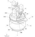
- FIG. 1 is a diagram showing a schematic configuration of an ultrasound treatment system.
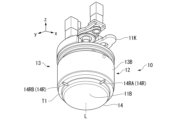
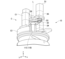
- FIG. 2 is a perspective view showing a configuration of an ultrasonic head device.
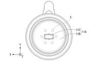
- FIG. 2 is a bottom view showing the configuration of the ultrasonic head device.
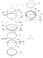
- FIG. 2 is an exploded perspective view showing a configuration of a moving mechanism.
- FIG. 2 is a cross-sectional view showing a configuration of an ultrasonic head device.
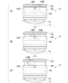
- 11A and 11B are diagrams illustrating the operation of a moving mechanism.
- FIG. 2 is a perspective view showing a configuration of a first drive unit.
- FIG. 4 is a perspective view showing a configuration of a second drive unit.
- FIG. 4 is a perspective view showing a configuration of a third drive unit.
- FIG. 1 is a diagram showing a schematic configuration of an ultrasound treatment system.
- FIG. 2 is a perspective view showing a configuration of an ultrasonic head device.
- FIG. 2 is a bottom view showing the configuration of the ultrasonic head device.
- FIG. 13 is a perspective view showing a configuration of a fourth drive unit.
- 5A to 5C are cross-sectional views showing the operation of the moving mechanism.
- 5A to 5C are cross-sectional views showing the operation of the moving mechanism.
- FIG. 1 is a block diagram showing the configuration of an ultrasound treatment system. 1 is a flowchart showing a control method for the ultrasound therapeutic system. 13 is a cross-sectional view showing a configuration of a moving mechanism according to a modified example.
- the ultrasonic therapy system S includes an ultrasonic therapy device 1 that controls the irradiation of ultrasonic waves, and a control device 40 that controls the ultrasonic therapy device 1 and manages the usage state, etc.
- the ultrasonic therapy device 1 includes a robot arm 2 that can support an object at any position and posture, an ultrasonic head device 10 provided at the tip of the robot arm 2, a liquid storage section 12 provided at the tip of the ultrasonic head device 10 and configured to have an adjustable volume, and a housing 20 provided with a fluid circuit section 25 that circulates an intermediate liquid in the liquid storage section 12 based on a control command from the control device 40.
- the robot arm 2 is, for example, a vertical articulated robot, and is installed on the floor via an arm base 4.
- the robot arm 2 is configured to be able to move the ultrasonic head device 10 to any position and hold it in any posture.
- the robot arm 2 can hold the ultrasonic head device 10 in a position where it abuts against the patient, or in a position spaced apart from the patient.
- the robot arm 2 can also hold the ultrasonic head device 10 in a posture where the central axis L of the ultrasonic head device 10 extends vertically, or in a posture where it is tilted from the vertical.
- the direction along the central axis L will be referred to as the "axial direction" or the like, as appropriate.
- the ultrasonic head device 10 irradiates the affected area of patient K with ultrasonic waves to perform treatment.
- the affected area may be, for example, cancer cells such as liver cancer, or stones.
- the subject of treatment based on ultrasonic waves may be animals as well as humans.
- the ultrasonic head device 10 includes a device that irradiates the subject with high intensity focused ultrasound (hereinafter referred to as HIFU), which is a type of therapeutic ultrasound, and a device that irradiates and receives diagnostic ultrasound, which is a type of ultrasound different from HIFU.
- HIFU high intensity focused ultrasound
- the ultrasonic head device 10 includes an irradiation unit 11A that irradiates ultrasonic waves to an affected area of a treatment target, for example, at the lower end inside the main body unit 11.
- the irradiation unit 11A includes, for example, a first irradiation unit 11B that generates HIFU for treatment, and a second irradiation unit 11C that is composed of a diagnostic probe that generates ultrasonic waves for diagnosis.
- the first irradiation unit 11B is, for example, configured with a HIFU transducer that irradiates HIFU to generate a focal point X.
- a dome-shaped irradiation surface 11B1 is provided on the underside of the first irradiation unit 11B, and a plurality of ultrasonic transducers (not shown) made of piezoelectric elements or the like are aligned and arranged on the inner surface of the irradiation surface 11B1.
- the plurality of ultrasonic transducers are arranged so that the envelopes of the plurality of ultrasonic waves oscillated are focused at one or more focal points X.
- the focal points X are generated at six locations on a plane perpendicular to the central axis L, at equal intervals around the central axis L.
- the number of focal points X generated may be one.
- the focal point X is generated on the central axis L.
- the first irradiation unit 11B may be arranged, for example, rotatably around the central axis L.
- the second irradiating unit 11C scans ultrasound on the treatment object to generate a cross-sectional image. For example, the second irradiating unit 11C irradiates diagnostic ultrasound at the tip of the patient K and receives diagnostic ultrasound reflected from the object, such as the affected area of the patient K. The second irradiating unit 11C protrudes downward from the irradiation surface 11B1 of the first irradiating unit 11B. The second irradiating unit 11C irradiates diagnostic ultrasound in a predetermined angular range with respect to the central axis L along the up-down direction and receives the reflected waves. The second irradiating unit 11C is provided so as to be rotatable along the central axis L. The second irradiating unit 11C is provided so as to be freely movable in a direction along the central axis L.
- the liquid storage section 12 has a water bag 14.
- the water bag 14 is formed in a hemispherical shape that bulges downward.
- the internal space of the water bag 14 is filled with an intermediary liquid that transmits ultrasound, as described below.
- the water bag 14 covers the irradiation surface 11B1 of the first irradiation section 11B and the second irradiation section 11C protruding from the irradiation surface 11B1.
- the irradiation surface 11B1 and the second irradiation section 11C are immersed in the intermediary liquid filled in the internal space of the water bag 14.
- the outside of the bottom of the water bag 14 abuts against the patient's body surface during diagnosis and treatment.
- the second irradiation section 11C is configured to be freely rotatable and movable along the vertical direction in the internal space filled with the intermediary liquid. For example, the tip of the second irradiation section 11C abuts against the inside of the bottom of the water bag 14 during diagnosis. As a result, the second irradiation section 11C abuts against the body surface of the patient K via the water bag 14, and diagnoses the inside of the patient K's body.
- the liquid storage section 12 is composed of, for example, a moving mechanism 13 that can be raised and lowered in the direction of the central axis L, a water bag 14, and an attachment section T for attaching the water bag 14 provided at the bottom of the moving mechanism 13.
- the liquid storage section 12 is configured so that the volume of the internal space filled with the intermediary liquid can be adjusted by the moving mechanism 13.
- the internal space of the liquid storage section 12 is formed, for example, by the water bag 14, the moving mechanism 13, and the first irradiation section 11B.
- the internal space of the liquid storage section 12 is filled with the intermediary liquid.
- the water bag 14 is configured so that it can be detached from the moving mechanism 13 and replaced as described below.
- the moving mechanism 13 is provided, for example, on a base 11K fixed to the main body 11.
- the main body 11 is supported by the robot arm 2 via the base 11K.
- the moving mechanism 13 is configured to be able to increase or decrease the volume of the internal space by allowing the water bag 14 to move up and down along the central axis L.
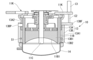
- the moving mechanism 13 includes, for example, a first cylindrical portion 13A provided on the base 11K side.
- the moving mechanism 13 includes a second cylindrical portion 13B having an attachment portion T on the lower side for attaching the water bag 14.
- the second cylindrical portion 13B is held movably in the central axis L direction.
- the moving mechanism 13 includes a moving drive unit that moves the second cylindrical portion 13B along the central axis L direction relative to the first cylindrical portion 13A.
- the moving drive unit is composed of a third cylindrical portion 13C and a first drive unit C described below.
- the first cylindrical portion 13A is formed, for example, in a cylindrical shape centered on the central axis L.
- a plurality of first groove portions 13A2 are formed on the outer peripheral surface 13A1 of the first cylindrical portion 13A.
- the first groove portions 13A2 are formed in linear groove shapes along the direction of the central axis L.
- the first groove portions 13A2 are formed, for example, at three locations evenly along the circumferential direction of the outer peripheral surface 13A1.
- the first groove portions 13A2 are formed, for example, in linear groove shapes of a predetermined length from the upper end portion of the first cylindrical portion 13A.
- the first groove portions 13A2 are formed in a groove shape having a predetermined depth from the outer peripheral surface 13A1 side.
- the area on the outer peripheral surface 13A1 below the lower end of the first groove portions 13A2 is a sliding area 13A3 in which the sealing member S1 described later slides.
- the first cylindrical portion 13A is inserted into the second cylindrical portion 13B, and the outer peripheral surface A1 of the first cylindrical portion 13A faces the inner peripheral surface 13B2 of the second cylindrical portion 13B, which will be described later.
- the second cylindrical portion 13B is formed, for example, in a cylindrical shape centered on the central axis L.
- the second cylindrical portion 13B has one or more through holes 13BH formed from the outer peripheral surface 13B1 to the inner peripheral surface 13B2.
- the through holes 13BH are provided at positions corresponding to the first groove portion 13A2 of the first cylindrical portion 13A, and are formed, for example, at three equal locations centered on the central axis L.
- An engaging member 13BP is inserted into each of the three through holes 13BH.
- the engaging member 13BP is formed as a cylindrical pin member.
- the engaging member 13BP is provided so as to protrude radially from the inner peripheral surface 13B2 side toward the central axis.
- the engaging member 13BP is formed so as to engage with the first groove portion 13A2 when the first cylindrical portion 13A is inserted into the second cylindrical portion 13B.
- the tip of the engaging member 13BP is guided by the first groove portion 13A2 and slides in the first groove portion 13A2.
- Either the first cylindrical portion 13A or the second cylindrical portion 13B has one or more first groove portions 13A2 formed along the central axis direction.
- Either the other of the first cylindrical portion 13A or the second cylindrical portion 13B has one or more engaging members 13BP formed to protrude along the radial direction and engage with the first groove portion 13A2.
- a roller (not shown) running along the first groove portion 13A2 may be provided at the tip of the engaging member 13BP.
- the engaging portion is configured by three engaging members 13BP.
- the second cylindrical portion 13B By guiding the engaging member 13BP into the first groove portion 13A2, the second cylindrical portion 13B is provided to be movable along the central axis L direction relative to the first cylindrical portion 13A.
- the second cylindrical portion 13B moves within a predetermined range of movement along the axial direction based on, for example, the rotation of the third cylindrical portion 13C described below.
- the third cylindrical portion 13C is rotationally driven by the first drive unit C.
- a seal groove portion 13BM into which a seal member S1 is fitted is formed in the lower part of the inner surface 13B2 of the second cylindrical portion 13B.
- the seal groove portion 13BM is provided, for example, below the inner surface 13B2 along the circumferential direction centered on the central axis L.
- the seal groove portion 13BM is provided extending along the circumferential direction of the inner surface 13B2.
- a seal member S1 formed in an annular shape that seals the gap between the outer surface 13A1 of the first cylindrical portion 13A and the sliding area 13A3 is fitted into the seal groove portion 13BM.
- One or more seal groove portions 13BM and seal members S1 may be provided along the axial direction.
- the seal groove portion 13BM and the seal member S1 form a seal portion.
- the seal portion is formed in the circumferential direction around the central axis L, and seals the gap between the inner circumferential surface 13B2 of the second cylindrical portion 13B and the sliding area 13A3 on the outer circumferential surface 13A1 of the first cylindrical portion 13A, ensuring watertightness.
- the outer circumferential surface 13B1 of the second cylindrical portion 13B is provided with an attachment portion T (see FIG. 2) that allows the water bag 14 to be attached and detached.
- the attachment portion T includes, for example, a plurality of buckles (not shown) evenly arranged around the circumferential surface 13B1, and an annular member T1 that is fixed by the plurality of buckles.
- the buckle is formed, for example, so that the annular member T1 can be attached and detached based on a lever operation.
- the annular member T1 is provided, for example, via a hinge structure (not shown) so that it can be opened and closed freely relative to the second cylindrical portion 13B.
- the end face 13BT of the lower end of the second cylindrical portion 13B is formed in a circular ring shape with a predetermined width.
- the end face 13BT abuts against the flange portion 14C (described below) provided at the upper end of the water bag 14.
- the annular member T2 engages with the flange portion 14C and cooperates with the end face 13BT of the lower end of the second cylindrical portion 13B to clamp the flange portion 14C.
- the annular member T2 cooperates with the mounting portion to allow the water bag 14 to be attached and detached, and also presses the flange portion 14C of the water bag 14 against the end face 13BT of the lower end of the second cylindrical portion 13B, ensuring watertightness between the second cylindrical portion 13B and the water bag 14.
- the moving drive unit includes a third cylindrical portion 13C and a first drive unit C (described later) that drives the third cylindrical portion 13C to rotate.
- the third cylindrical portion 13C is held rotatably about the central axis L, and a part of the third cylindrical portion 13C is inserted into the gap between the inner peripheral surface 13B2 of the second cylindrical portion 13B and the outer peripheral surface 13A1 of the first cylindrical portion 13A.
- the third cylindrical portion 13C includes, for example, a ring member 13C1 formed in an annular shape and a cylindrical portion 13C2 formed hanging down from the ring member 13C1.
- a flange portion 13CF is formed at the upper end of the ring member 13C1 and extends radially from the central axis L. The flange portion 13CF abuts against the upper end of the first cylindrical portion 13A.
- the cylindrical portion 13C2 is inserted into the gap between the inner peripheral surface 13B2 of the second cylindrical portion 13B and the outer peripheral surface 13A1 of the first cylindrical portion 13A.
- a second groove portion 13CM inclined along the central axis direction is formed in the circumferential direction with respect to the central axis.
- the second groove portion 13CM is formed, for example, with a length of less than one circumference of a spiral track having a predetermined pitch interval around a predetermined direction centered on the central axis L.
- An engaging member 13BP (engagement portion) provided on the second cylindrical portion 13B penetrates each second groove portion 13CM.
- the upper end side of the second groove portion 13CM is, for example, the starting point of the second groove portion 13CM.
- the lower end side of the second groove portion 13CM is, for example, the end point of the second groove portion 13CM.
- Figure 4C (B) shows the initial state (or standby state) of the ultrasonic head device 10 before the operator operates the ultrasonic treatment system S for treatment.
- the engagement member 13BP is located near the middle between the first groove portion 13A2 and the second groove portion 13CM.
- the engagement member 13BP rises following the first groove portion 13A2 as the second groove portion 13CM moves to the right.
- the second cylindrical portion 13B also rises. This action brings the water bag 14 closer to the irradiation surface 11B1, reducing the volume of the internal space of the liquid storage portion 12.
- the second cylindrical portion 13B can move any amount along the axial direction within the range in which the engaging member 13BP is guided by the second groove portion 13CM and the first groove portion 13A2.
- the inclination angle between the plane perpendicular to the central axis L and the second groove portion 13CM gentle, it is possible to reduce the force required for the first drive portion C (described below) to rotate the third cylindrical portion 13C. This makes it possible to reduce the size of the drive source used for the first drive portion C, making it possible to miniaturize the device configuration.
- the engaging member in the initial state, is located near the middle of the second groove portion, but, for example, in the initial state, the engaging member may be located at the start point (upper end) or end point (lower end) of the second groove portion.
- the third cylindrical portion 13C is driven to rotate in the circumferential direction about the central axis L relative to the first cylindrical portion 13A and the second cylindrical portion 13B by the first drive portion C described below, thereby moving the engagement member 13BP along the second groove portion 13CM and the first groove portion 13A2, and the second cylindrical portion can be moved an arbitrary amount along the axial direction of the central axis L relative to the first cylindrical portion based on the direction of rotation.
- the water bag 14 is formed, for example, in a bowl shape that bulges downward.
- the water bag 14 is made of a material that is biocompatible and has an acoustic impedance similar to that of a living body.
- the water bag 14 is formed, for example, of a flexible material such as silicone rubber.
- the water bag 14 is formed so that it can be replaced after each treatment.
- a contact portion 14A that comes into contact with the body of the patient K is formed on the underside of the water bag 14.
- the contact portion 14A is formed in a semispherical tray shape.
- a cylindrical peripheral wall portion 14B is formed around the contact portion 14A, the lower part of which is continuous with the contact portion and extends to surround the upper part of the periphery of the contact portion.
- the peripheral wall portion 14B is formed, for example, in a truncated cone shape whose diameter increases as it goes upward.
- the peripheral wall portion 14B is attached to the attachment target portion (not shown) of the ultrasonic head device 10.
- a flange portion 14C that engages with the attachment target portion is formed at the upper end of the peripheral wall portion 14B.
- the flange portion 14C is formed in a circular ring shape that protrudes outward in the horizontal direction.
- the peripheral wall 14B is provided with a water supply and drainage section 14R that circulates the intermediary liquid through the water bag via the fluid circuit section 25.
- the water supply and drainage section 14R has an inflow connection section 14RA through which the intermediary liquid flows in from the fluid circuit section 25, and a drain connection section 14RB through which the intermediary liquid is discharged from the water bag 14.
- the inflow connection section 14RA is provided at a first position on the peripheral wall 14B.
- the inflow connection section 14RA is connected to a flow path of the fluid circuit section 25.
- the drain connection section 14RB is provided at a second position different from the first position on the peripheral wall 14B in a plan view. The second position is, for example, a position 90 degrees from the center of the contact section 14A with respect to the first position in a plan view.
- the drain connection section 14RB is connected to the flow path of the fluid circuit section 25.
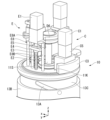
- FIG. 5 shows the internal structure of the main body 11 of the ultrasonic head device 10.
- the third cylindrical portion 13C is driven to rotate around the central axis L by the first drive unit C.
- the first drive unit C is composed of, for example, a first motor serving as the drive source C1, a first gear (not shown) driven to rotate by the first motor, and a second gear C3 meshing with the first gear.
- a reducer C5 is provided between the first motor and the first gear to reduce the rotation speed of the first motor and increase the torque of the rotation output. If the first motor has sufficient torque, the reducer C5 does not necessarily have to be provided.
- the first motor has a rotating shaft (not shown) along the central axis L, and a first gear is provided below the rotating shaft.
- the first gear is, for example, a pinion gear.
- the first motor is fixed to the base portion 11K that fixes the first cylindrical portion 13A side via a fixing member C6.
- the first motor transmits rotational power to the second gear C3 via the first gear.
- the second gear C3 is formed, for example, as an internal gear (rack gear) having an outer diameter equal to the outer diameter of the first cylindrical portion 13A.
- the second gear C3 is formed by cutting out a part of the internal gear in a predetermined angle range centered on the central axis L.
- the second gear C3 is formed in a predetermined angle range in which the above-mentioned engagement member 13BP can move relatively along the second groove portion 13CM from the end to the start of the second groove portion 13CM.
- the second gear C3 is, for example, screwed to the upper end of the third cylindrical portion 13C via the base portion 11K.
- the first gear which is the output part C2
- a driving force is transmitted to the second gear C3
- the third cylindrical part 13C is rotated about the central axis L via the second gear C3.
- the second cylindrical part 13B moves an arbitrary amount of movement within a predetermined range along the axial direction relative to the first cylindrical part 13A.
- the water bag 14 is formed in a bowl shape that bulges downward, and the moving mechanism 13 is configured to move the second cylindrical part 13B and the water bag 14 attached below the second cylindrical part 13B relative to the first cylindrical part 13A. Therefore, compared to when the water bag 14 has a bellows-like expandable structure, it is possible to prevent air bubbles from being mixed in when filling the internal space of the liquid storage part 12 with the intermediate liquid after replacing the water bag 14.
- the second irradiation unit 11C (see FIG. 4B) is rotated by the second drive unit D around the central axis L.
- the second drive unit D is composed of, for example, a second motor D1 serving as a drive source, a first pulley D2 rotated by the second motor D1, a first belt D3 transmitting the rotational power of the first pulley D2, and a second pulley D4 rotated by the first belt D3.
- a reducer D5 is provided to reduce the rotation speed of the second motor D1 and increase the torque of the rotation output. If the torque of the second motor D1 is sufficiently secured, the reducer D5 does not necessarily have to be provided.
- the second motor D1 has a rotation shaft (not shown) along the central axis L, and the first pulley D2 is provided below the rotation shaft.
- the first pulley D2 for example, has a first belt D3 looped around it.
- the second pulley D4 is formed with a diameter larger than that of the first pulley D2.
- the second pulley D4 is concentrically connected to a shaft 11S connected to a second irradiation unit 11C (see FIG. 2).
- the shaft 11S extends above the second irradiation unit 11C.
- the second irradiation unit 11C is provided at the lower end of the shaft 11S.
- the shaft 11S is supported by the base unit 11K so as to be rotatable around the central axis L and is supported so as to be movable along the central axis L.
- the second pulley D4 increases the torque of the rotation output of the first pulley D2 to rotate the second irradiation unit 11C via the shaft 11S.
- the second motor D1 is fixed via a support member D6.
- the support member D6 regulates the circumferential movement of the second motor D1 around the central axis L.
- the support member D6 moves along the central axis L direction as described below.
- the first irradiation unit 11B (see FIG. 4B) is configured to be movable along the central axis L direction via the shaft 11S by the third drive unit E.
- the third drive unit E is configured, for example, to include a third motor E1 serving as a drive source, a support unit E8 supporting the third motor E1, a ball screw E2 driven and rotated by the third motor E1, a sliding nut E3 screwed onto the ball screw E2, a base E4 supporting the sliding nut E3, and a connecting member E5 connecting the base E4 to a support member D6 supporting the second motor D1.
- the third motor E1 is fixed to the base 11K by a support E8.
- the support E8 includes, for example, a fixing member E8A that fixes the third motor E1.
- the fixing member E8A is fixed to the base 11K by two pillars E8B.
- the third motor E1 has a rotating shaft (not shown) that runs along the central axis L, and a ball screw E2 is connected to the lower part of the rotating shaft.
- a screw groove is formed in the ball screw E2.
- the lower end side of the ball screw E2 is rotatably supported by the base 11K via a bearing EB.
- a sliding nut E3 is screwed onto the ball screw E2.
- the sliding nut E3 is formed with a female thread (not shown) into which the thread groove of the ball screw E2 screws.
- the sliding nut E3 is supported by a base E4.
- the base E4 is fixed to a support member D6 via a connecting member E5.
- the base E4 is positioned via the support member D6 and the shaft 11S.
- the base E4 is restricted from rotating around the rotation axis of the ball screw E2 by the support member D6 and the shaft 11S.
- FIG. 8 shows the fourth drive unit F that drives the first irradiation unit 11B (see FIG. 3 and FIG. 4B) to rotate around the central axis L.
- the first irradiation unit 11B is configured to be rotatable around the central axis L by the fourth drive unit F.
- the fourth drive unit F is configured, for example, with a fourth motor F1 as a drive source, a third pulley F2 that is driven to rotate by the fourth motor F1, a second belt F3 that transmits the rotational power between the third pulley F2, and a fourth pulley F4 that is driven to rotate by the second belt F3.
- a reducer F5 is provided that reduces the rotation speed of the fourth motor F1 and increases the torque of the rotation output. If the torque of the fourth motor F1 is sufficiently secured, the reducer F5 does not necessarily have to be provided.
- the fourth motor F1 has a rotation shaft (not shown) along the central axis L, and the third pulley F2 is provided below the rotation shaft.
- the third pulley F2 is fitted with, for example, a second belt F3.
- the fourth pulley F4 is formed with a diameter larger than that of the third pulley F2.
- the fourth pulley F4 is fitted with a second belt F3.
- a through hole F4H is provided at the center of the fourth pulley F4, and a shaft 11S passes through the through hole F4H.
- the first irradiation unit 11B is provided on the underside of the fourth pulley F4 so as to be rotatable around the central axis L direction.
- the fourth motor F1 is fixed to the reducer F5.
- the reducer F5 is fixed to the base unit 11K side by the support unit F8.
- the fourth pulley F4 increases the torque of the rotation output of the third pulley F2 to rotate the first irradiation unit 11B.
- the fourth pulley F4 rotates via the second belt F3, and the first irradiation unit 11B is rotated.
- the rotatable range is at least 360°/n (360°/n in one direction, or 180°/n in both directions).
- the first irradiation unit 11B does not need to be rotationally driven.
- the second irradiation unit 11C rotates when determining the position and posture, so the focal point X of the first irradiation unit 11B may not coincide with the imaging plane of the second irradiation unit 11C. Since the treatment using ultrasound is localized, if the focal point X does not coincide with the imaging plane, the treatment situation cannot be accurately imaged, and there is a risk of the treatment accuracy decreasing. Therefore, it is necessary to match one of the multiple focal points X with the imaging plane. Since it does not matter which focal point coincides, the rotatable range of the first irradiation unit 11B may be the range described above.
- the affected area KD is present inside the body of the patient K.
- the second irradiation unit 11C abuts against the inner wall of the water bag 14 and abuts against the body surface of the patient K via the water bag 14.
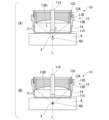
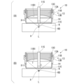
- the second irradiation unit 11C is raised and the operator operates the robot arm 2 to move the ultrasonic head device 10 downward. This allows the position of the focus X to coincide with the position of the affected area KD (see FIG. 9(B)).
- the fluid circuit unit 25 discharges the intermediate liquid in the water bag 14, rotates the third cylindrical portion 13C in the moving mechanism 13, and raises the second cylindrical portion 13B relative to the first cylindrical portion 13A. This makes it possible to bring the water bag 14 into contact with the body surface of the patient K while maintaining an appropriate amount of water and pressure of the intermediary liquid in the liquid storage section 12. As a result, the ultrasonic waves used in treatment can be appropriately transmitted from the ultrasonic head device 10 to the affected area via the intermediary liquid.
- the affected area KD is present inside the body of the patient K.
- the second irradiation unit 11C abuts against the inner wall of the water bag 14 and abuts against the body surface of the patient K through the water bag 14.
- the operator operates the robot arm 2 to move the ultrasonic head device 10 upward.
- the second irradiation unit 11C is lowered and abuts against the body surface of the patient K through the water bag 14. This allows the position of the focus X to match the position of the affected area KD (see FIG. 10(B)).
- the fluid circuit section 25 supplies the intermediary liquid into the water bag 14, rotates the third cylindrical section 13C in the movement mechanism 13, and lowers the second cylindrical section 13B relative to the first cylindrical section 13A.
- the ultrasonic head device 10 can adjust the distance of the water bag 14 from the irradiation surface 11B1 and the amount of water of the intermediary liquid filled in the water bag 14 depending on the position of the affected area KD from the patient's body surface. This makes it possible to maintain the water pressure in the water bag 14 and the contact surface between the water bag 14 and the patient's body surface in an appropriate state. As a result, the ultrasonic waves used in treatment can be appropriately transmitted from the ultrasonic head device 10 to the affected area via the intermediary liquid.
- the supply and discharge of the intermediary liquid by the fluid circuit unit 25 may be performed before or after the movement operation of the movement mechanism 13, or may be performed simultaneously with the movement operation.
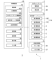
- FIG. 11 shows the configuration of the ultrasonic therapy system S in a block diagram.
- the control device 40 controls the ultrasonic therapy device 1 including the robot arm 2, the ultrasonic head device 10, and the fluid circuit section 25.
- the control device 40 is configured, for example, with an information processing terminal device such as a personal computer.
- the control device 40 is communicatively connected to the ultrasonic therapy device 1.
- the control device 40 may be directly connected to the ultrasonic therapy device 1, or it may be a server connected to a network and communicatively connected to the ultrasonic therapy device 1.
- the control device 40 includes a control unit 42 that controls the ultrasonic therapy device 1.
- the control device 40 includes a memory unit 46 that stores data necessary for control, a communication unit 47 that communicates with the ultrasonic therapy device 1, a display unit 48 that displays information necessary for control, and an input unit 49 that accepts operations necessary for control.
- the memory unit 46 is a data storage device composed of a storage medium such as a hard disk drive or flash memory.
- the memory unit 46 may be built into the control device 40, or may be connected to the outside as an external storage device.
- the communication unit 47 is a communication interface that transmits and receives control signals to and from the ultrasonic treatment device 1.
- the communication unit 47 receives command signals requesting control and detection signals detected from the ultrasonic treatment device 1, and transmits control signals for controlling the ultrasonic treatment device 1.
- the display unit 48 is composed of a display device such as a liquid crystal display or an organic electro-luminescence (EL) display.
- the input unit 49 is an information input device such as a touchpad such as a keyboard. If the display unit 48 is configured to be touch operable, the input unit 49 may be configured integrally with the display unit 48.
- the display unit 48 displays a display image including information related to the control of the ultrasonic treatment device 1.
- the display unit 48 displays a diagnostic image of the body of the patient K generated based on the detection value detected by the second irradiation unit 11C.
- the control unit 42 includes the following multiple control units to individually control the ultrasonic treatment device 1.
- the control unit 42 includes, for example, a main control unit 42A that performs integrated control of the ultrasonic treatment device 1 based on information input from the input unit 49.
- the control unit 42 includes, for example, a robot arm control unit 42B that controls the robot arm 2 based on commands input from the input unit 49.
- the control unit 42 includes, for example, an ultrasonic head control unit 42C that controls the ultrasonic head device 10 based on commands input from the input unit 49.
- the control unit 42 includes, for example, a fluid delivery control unit 42D that controls the fluid circuit unit 25 based on commands input from the input unit 49.
- the main control unit 42A generates a command signal for controlling the ultrasonic therapy device 1 based on, for example, information input from the input unit 49.
- the main control unit 42A performs integrated control in cooperation with each of the control units described below so that the ultrasonic therapy device 1 operates in cooperation with each other.
- the main control unit 42A is composed of, for example, a central processing unit provided in the control device 40.
- the robot arm control unit 42B controls the drive unit 3A provided on the robot arm 2.
- the robot arm control unit 42B may be provided on the robot arm 2 side, for example, or may be integrated into the control unit 42 of the control device 40.
- the robot arm control unit 42B for example, individually controls multiple drive motors provided on multiple joints of the robot arm 2.
- the robot arm control unit 42B acquires a command signal requesting a specific operation from the robot arm 2, calculates the individual control amounts of the multiple drive motors based on the contents of the command signal, and generates a control signal.
- the robot arm control unit 42B acquires detection data from the detection unit 3B provided on the drive unit 3A, which detects the rotation angle, torque, etc. of each drive motor.
- the robot arm control unit 42B generates a control signal according to the posture of the multiple arm members 3-n and the magnitude and direction of the applied force based on the data acquired from the detection unit 3B, and controls the robot arm 2.
- the robot arm 2 may also be a collaborative robot. In this case, when the operator applies force to change the posture of the robot arm 2, the robot arm control unit 42B individually controls multiple drive motors to change the position and posture of the ultrasonic head device 10 in accordance with the operator's operation.
- the robot arm control unit 42B transmits a control signal to the robot arm 2 via the communication unit 47, and controls the robot arm 2 to perform a predetermined operation.
- the robot arm control unit 42B acquires data on the drive amount of each joint of the robot arm 2 via the communication unit 47, and adjusts the operation of the robot arm 2.
- the robot arm control unit 42B controls the robot arm 2 during treatment, for example, to position the focal point X of the first irradiation unit 11B of the ultrasonic head device 10 provided on the robot arm 2 at the position of the affected area KD of the patient K, and maintains the robot arm in a predetermined posture.
- the robot arm control unit 42B controls the robot arm 2 during treatment preparation after the treatment is completed, for example, as described below, to maintain the ultrasonic head device 10 in a predetermined first posture so that the intermediary liquid can be easily discharged from the liquid storage unit 12 of the ultrasonic head device 10.
- the robot arm control unit 42B controls the robot arm 2 during treatment preparation before the treatment is started, for example, as described below, to maintain the ultrasonic head device 10 in a predetermined second posture so that the intermediary liquid can be easily supplied to the liquid storage unit 12 of the ultrasonic head device 10.
- the ultrasonic head control unit 42C controls the ultrasonic head device 10 based on the acquired command signal to perform the required operation.
- the ultrasonic head control unit 42C may be provided on the ultrasonic head device 10 side, or may be integrated into the control unit 42 of the control device 40.
- the ultrasonic head control unit 42C acquires a command signal requesting the ultrasonic head device 10 to perform a predetermined operation, calculates the individual control amounts of the multiple irradiation units based on the contents of the command signal, and generates a control signal.
- the ultrasonic head control unit 42C transmits the control signal to the ultrasonic head device 10 via the communication unit 47, and controls the ultrasonic head device 10 to perform the required operation.
- the ultrasonic head control unit 42C controls, for example, the first drive unit C to rotate the third cylindrical unit 13C, adjusts the amount of movement along the axial direction of the second cylindrical unit 13B, and controls the position of the water bag 14 from the irradiation surface 11B1.
- the ultrasonic head control unit 42C also controls the fourth drive unit F to rotate the first irradiation unit 11B around the central axis L, and aligns the scanning plane of the second irradiation unit 11C with one of the multiple focal points X of the therapeutic ultrasound.
- the ultrasonic head control unit 42C controls the third drive unit E to adjust the amount of movement of the shaft 11S, and abuts the second irradiation unit 11C against the inner wall of the water bag 14.
- the ultrasonic head control unit 42C controls the second drive unit D to rotate the second irradiation unit 11C around the central axis L, and adjusts the scanning direction of the diagnostic ultrasound with respect to the affected area KD.
- the liquid supply control unit 42D controls a plurality of circuit control devices, which are constituted by the pump unit 26 and the valve unit 27 provided in the fluid circuit unit 25, to circulate the intermediate liquid through the fluid circuit unit 25.
- the fluid circuit unit 25 is configured as a water supply and drainage mechanism that supplies the intermediate liquid to the water bag 14 and discharges the intermediate liquid from the water bag 14.
- the liquid supply control unit 42D controls the pump unit 26 and the valve unit 27 to cause the intermediate liquid to flow from the fluid circuit unit 25 into the water bag 14 via the inlet connection unit 14RA.
- the liquid supply control unit 42D controls the pump unit 26 and the valve unit 27 to discharge the intermediate liquid from the water bag 14 to the fluid circuit unit 25 via the outlet connection unit 14RB.
- the liquid delivery control unit 42D controls the fluid circuit unit 25 in conjunction with the ultrasonic head control unit 42C.
- the liquid delivery control unit 42D controls the water supply and drainage mechanism to fill the internal space of the water bag 14, which changes in response to the movement, with the intermediate liquid.
- the liquid delivery control unit 42D may be provided on the housing 20 side, or may be integrated into the control unit 42 of the control device 40.
- the liquid delivery control unit 42D obtains a command signal that requests a specific operation from the multiple circuit control devices, calculates the individual control amounts of the multiple circuit control devices based on the contents of the command signal, and generates a control signal.
- the liquid delivery control unit 42D transmits the control signal to the multiple circuit control devices via the communication unit 47, and controls the multiple circuit control devices to perform the required operation.
- the fluid supply control unit 42D controls the fluid circuit unit 25 to adjust the amount of intermediate liquid stored in the liquid storage unit 12.
- the fluid supply control unit 42D controls the fluid circuit unit 25 to drain the intermediate liquid from the liquid storage unit 12 and also drains the intermediate liquid from the fluid circuit unit 25.
- the fluid supply control unit 42D controls the fluid circuit unit 25 to supply new intermediate liquid to the fluid circuit unit 25 and also supplies intermediate liquid to the liquid storage unit 12.
- the components constituting the control unit 42 described above are realized by, for example, a hardware processor such as a CPU (Central Processing Unit) executing a program (software). Some or all of these components may be realized by hardware (including circuitry) such as an LSI (Large Scale Integration), an ASIC (Application Specific Integrated Circuit), an FPGA (Field-Programmable Gate Array), or a GPU (Graphics Processing Unit), or may be realized by a combination of software and hardware.
- a hardware processor such as a CPU (Central Processing Unit) executing a program (software).
- Some or all of these components may be realized by hardware (including circuitry) such as an LSI (Large Scale Integration), an ASIC (Application Specific Integrated Circuit), an FPGA (Field-Programmable Gate Array), or a GPU (Graphics Processing Unit), or may be realized by a combination of software and hardware.
- the program may be stored in advance in a storage device (a storage device having a non-transient storage medium) such as an HDD (Hard Disk Drive) or a flash memory, or may be stored in a removable storage medium (non-transient storage medium) such as a DVD or a CD-ROM, and installed in the storage device by mounting the storage medium in a drive device.
- a storage device a storage device having a non-transient storage medium
- a storage device having a non-transient storage medium such as an HDD (Hard Disk Drive) or a flash memory
- a removable storage medium non-transient storage medium
- the processing executed by the control unit 42 may be performed by a computer on a server using cloud computing.
- the processing executed by the control unit 42 may be performed in a distributed manner by distributing the functions among multiple distributed computers.
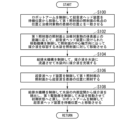
- FIG. 12 shows the process flow of the control method executed in the ultrasonic treatment system S.
- the robot arm control unit 42B controls the robot arm 2 to move the ultrasonic head device 10 supported by the robot arm 2 from the standby position (movement step), and aligns the position of the focal point X of the irradiation surface 11B1 of the first irradiation unit 11B with the position of the affected area of the treatment object (alignment step) (step S100).
- the ultrasonic head control unit 42C controls the movement mechanism 13 provided on the ultrasonic head device 10 according to the distance between the irradiation surface 11B1 of the first irradiation unit 11B and the body surface of the treatment object, to move the water bag 14 containing the intermediary liquid along the central axis direction of the irradiation surface 11B1 relative to the irradiation surface 11B1 (first movement step) (step S102).
- the liquid supply control unit 42D controls the water supply and drainage mechanism to circulate the intermediate liquid through the water bag to supply the intermediate liquid into the water bag (supply step) (step S104).
- the ultrasonic head control unit 42C controls the ultrasonic head device to irradiate the affected area with ultrasonic waves from the irradiation surface 11B1 of the first irradiation unit 11B (irradiation step) (step S106).
- the control unit 42 controls the water supply and drainage mechanism to discharge the intermediate liquid from the internal space of the water bag 14 (discharge step), controls the first drive unit to move the water bag 14 to return it to its initial state (second movement step), and controls the robot arm 2 to move the ultrasonic head device 10 to its standby position (step S108).
- the control unit 42 may also control the robot arm 2 to move the ultrasonic head device 10 to its standby position, and then control the water supply and drainage mechanism to discharge the intermediate liquid from the internal space of the water bag 14, and control the first drive unit to move the water bag 14 to return it to its initial state.
- the above steps may be interchanged as appropriate, or may be performed simultaneously.
- the position of the focus X of the HIFU irradiated by the first irradiation unit 11B can be adjusted to the position of the affected area KD by manipulating the robot arm 2 to manipulate the position and orientation of the ultrasonic head device 10.
- the volume and water pressure of the liquid storage unit 12 can be set to appropriate values according to the distance between the irradiation surface 11B1 of the first irradiation unit 11B and the body surface of the patient K by making the water bag 14 movable in the axial direction using the movement mechanism 13.
- the ultrasonic waves used in treatment can be appropriately transmitted from the ultrasonic head device 10 to the affected area via the intermediate liquid.
- the moving mechanism 13 is configured so that the second cylindrical portion 13B moves relative to the first cylindrical portion 13A, and the water bag 14 is formed in a bowl shape that bulges downward, which prevents air bubbles from being mixed into the intermediary liquid when the intermediary liquid is filled inside the water bag 14.
- the force required to rotate the second cylindrical portion 13B can be reduced by making the angle between the second groove portion 13CM formed in the third cylindrical portion 13C and the plane perpendicular to the central axis L gentle, which in turn allows the first drive unit C and the device configuration to be made more compact.
- the moving mechanism 13 may be driven by a first driving unit C provided on a base portion 11K formed to protrude in the outer circumferential direction of the ultrasonic head device 10.
- the first driving unit C is composed of a linear driving device such as an electric cylinder or an air cylinder.
- the first driving unit C has a cylinder body serving as a driving source C1 and a rod serving as an output portion C2.
- the first driving unit C is provided with a cylinder body fixed to the base portion 11K, and the fixing portion of the rod and the second cylindrical portion flange 13BF described later is located outside the outer circumferential surface 13B1 of the second cylindrical portion 13B in a plan view.
- the rod extends in the axial direction, and its lower end is fixed to the second cylindrical portion flange 13BF provided on the second cylindrical portion 13B.
- the second cylindrical portion 13B can be moved relative to the first cylindrical portion 13A by extending and contracting the rod in the axial direction.
- the second cylindrical portion 13B is configured to move within a range of a predetermined amount of movement along the axial direction relative to the first cylindrical portion 13A.
- one or more first grooves 13A2 may be formed on the outer peripheral surface 13A1 of the first cylindrical portion 13A along the central axis direction of the first cylindrical portion 13A, and one or more engagement members 13BP may be provided in the second cylindrical portion 13B that protrude along the radial inner side and are formed to engage with the first grooves 13A2, or one or more first grooves (not shown) may be formed on the inner peripheral surface 13B2 of the second cylindrical portion 13B along the central axis direction of the second cylindrical portion 13B, and one or more engagement members (not shown) may be provided in the first cylindrical portion 13A that protrude along the radial outer side and are formed to engage with the first grooves (not shown).
- the third cylindrical portion 13C may not be provided in the moving mechanism 13 according to the modified example.
Landscapes
- Health & Medical Sciences (AREA)
- Life Sciences & Earth Sciences (AREA)
- Surgery (AREA)
- Engineering & Computer Science (AREA)
- General Health & Medical Sciences (AREA)
- Veterinary Medicine (AREA)
- Nuclear Medicine, Radiotherapy & Molecular Imaging (AREA)
- Public Health (AREA)
- Animal Behavior & Ethology (AREA)
- Biomedical Technology (AREA)
- Heart & Thoracic Surgery (AREA)
- Medical Informatics (AREA)
- Molecular Biology (AREA)
- Physics & Mathematics (AREA)
- Radiology & Medical Imaging (AREA)
- Vascular Medicine (AREA)
- Biophysics (AREA)
- Pathology (AREA)
- Orthopedic Medicine & Surgery (AREA)
- Acoustics & Sound (AREA)
- Robotics (AREA)
- Surgical Instruments (AREA)
- Physical Water Treatments (AREA)
Priority Applications (7)
| Application Number | Priority Date | Filing Date | Title |
|---|---|---|---|
| EP22960919.3A EP4595902A4 (en) | 2022-09-29 | 2022-09-29 | ULTRASONIC HEAD DEVICE, ULTRASONIC THERAPY SYSTEM AND METHOD FOR CONTROLLING THE ULTRASONIC THERAPY SYSTEM |
| KR1020257009968A KR20250056238A (ko) | 2022-09-29 | 2022-09-29 | 초음파 헤드장치, 초음파 치료시스템 및 초음파 치료시스템의 제어방법 |
| US19/116,653 US20260102175A1 (en) | 2022-09-29 | 2022-09-29 | Ultrasonic head device, ultrasonic therapy system, and method for controlling ultrasonic therapy system |
| JP2023551670A JP7453655B1 (ja) | 2022-09-29 | 2022-09-29 | 超音波ヘッド装置、及び超音波治療システム |
| CN202280100495.8A CN119947657A (zh) | 2022-09-29 | 2022-09-29 | 超声波头装置、超声波治疗系统、以及超声波治疗系统的控制方法 |
| PCT/JP2022/036464 WO2024069859A1 (ja) | 2022-09-29 | 2022-09-29 | 超音波ヘッド装置、超音波治療システム、及び超音波治療システムの制御方法 |
| TW112136991A TWI866496B (zh) | 2022-09-29 | 2023-09-27 | 超音波頭裝置、及超音波治療系統 |
Applications Claiming Priority (1)
| Application Number | Priority Date | Filing Date | Title |
|---|---|---|---|
| PCT/JP2022/036464 WO2024069859A1 (ja) | 2022-09-29 | 2022-09-29 | 超音波ヘッド装置、超音波治療システム、及び超音波治療システムの制御方法 |
Publications (1)
| Publication Number | Publication Date |
|---|---|
| WO2024069859A1 true WO2024069859A1 (ja) | 2024-04-04 |
Family
ID=90273402
Family Applications (1)
| Application Number | Title | Priority Date | Filing Date |
|---|---|---|---|
| PCT/JP2022/036464 Ceased WO2024069859A1 (ja) | 2022-09-29 | 2022-09-29 | 超音波ヘッド装置、超音波治療システム、及び超音波治療システムの制御方法 |
Country Status (7)
| Country | Link |
|---|---|
| US (1) | US20260102175A1 (cg-RX-API-DMAC7.html) |
| EP (1) | EP4595902A4 (cg-RX-API-DMAC7.html) |
| JP (1) | JP7453655B1 (cg-RX-API-DMAC7.html) |
| KR (1) | KR20250056238A (cg-RX-API-DMAC7.html) |
| CN (1) | CN119947657A (cg-RX-API-DMAC7.html) |
| TW (1) | TWI866496B (cg-RX-API-DMAC7.html) |
| WO (1) | WO2024069859A1 (cg-RX-API-DMAC7.html) |
Cited By (1)
| Publication number | Priority date | Publication date | Assignee | Title |
|---|---|---|---|---|
| JP7887211B1 (ja) * | 2025-10-06 | 2026-07-09 | ソニア・セラピューティクス株式会社 | Hifu照射装置 |
Citations (4)
| Publication number | Priority date | Publication date | Assignee | Title |
|---|---|---|---|---|
| JPH091845A (ja) | 1995-06-20 | 1997-01-07 | Nec Eng Ltd | 記録装置 |
| JP2000023990A (ja) * | 1999-07-12 | 2000-01-25 | Toshiba Corp | 超音波治療装置 |
| JP2020036709A (ja) | 2018-09-03 | 2020-03-12 | 株式会社デンソー | 治療装置 |
| JP2020039397A (ja) * | 2018-09-06 | 2020-03-19 | 株式会社デンソー | 作業装置 |
Family Cites Families (3)
| Publication number | Priority date | Publication date | Assignee | Title |
|---|---|---|---|---|
| JP2644237B2 (ja) | 1987-09-30 | 1997-08-25 | 株式会社東芝 | 超音波治療装置 |
| KR101677903B1 (ko) * | 2016-05-16 | 2016-11-21 | 정성재 | 초음파 카트리지와 이를 이용한 초음파 치료용 헤드 |
| JP7316924B2 (ja) * | 2019-12-24 | 2023-07-28 | 京セラ株式会社 | 超音波放射器具及び超音波装置 |
-
2022
- 2022-09-29 KR KR1020257009968A patent/KR20250056238A/ko active Pending
- 2022-09-29 EP EP22960919.3A patent/EP4595902A4/en active Pending
- 2022-09-29 CN CN202280100495.8A patent/CN119947657A/zh active Pending
- 2022-09-29 US US19/116,653 patent/US20260102175A1/en active Pending
- 2022-09-29 JP JP2023551670A patent/JP7453655B1/ja active Active
- 2022-09-29 WO PCT/JP2022/036464 patent/WO2024069859A1/ja not_active Ceased
-
2023
- 2023-09-27 TW TW112136991A patent/TWI866496B/zh active
Patent Citations (4)
| Publication number | Priority date | Publication date | Assignee | Title |
|---|---|---|---|---|
| JPH091845A (ja) | 1995-06-20 | 1997-01-07 | Nec Eng Ltd | 記録装置 |
| JP2000023990A (ja) * | 1999-07-12 | 2000-01-25 | Toshiba Corp | 超音波治療装置 |
| JP2020036709A (ja) | 2018-09-03 | 2020-03-12 | 株式会社デンソー | 治療装置 |
| JP2020039397A (ja) * | 2018-09-06 | 2020-03-19 | 株式会社デンソー | 作業装置 |
Non-Patent Citations (1)
| Title |
|---|
| See also references of EP4595902A4 |
Cited By (1)
| Publication number | Priority date | Publication date | Assignee | Title |
|---|---|---|---|---|
| JP7887211B1 (ja) * | 2025-10-06 | 2026-07-09 | ソニア・セラピューティクス株式会社 | Hifu照射装置 |
Also Published As
| Publication number | Publication date |
|---|---|
| TWI866496B (zh) | 2024-12-11 |
| US20260102175A1 (en) | 2026-04-16 |
| JP7453655B1 (ja) | 2024-03-21 |
| CN119947657A (zh) | 2025-05-06 |
| KR20250056238A (ko) | 2025-04-25 |
| EP4595902A4 (en) | 2026-07-08 |
| TW202428233A (zh) | 2024-07-16 |
| EP4595902A1 (en) | 2025-08-06 |
| JPWO2024069859A1 (cg-RX-API-DMAC7.html) | 2024-04-04 |
Similar Documents
| Publication | Publication Date | Title |
|---|---|---|
| CN1897907B (zh) | 带有移动控制的超声治疗头 | |
| JP5300871B2 (ja) | 超音波システムを伴う使用のための治療ヘッド | |
| US20110144544A1 (en) | Ultrasound transducer assembly and methods of using | |
| US20100249669A1 (en) | Ultrasonic treatment of adipose tissue at multiple depths | |
| KR101688424B1 (ko) | 초음파 카트리지와 이를 이용한 초음파 치료용 헤드 | |
| CN107073290B (zh) | 超声波套筒及利用其的超声波治疗头 | |
| KR101713318B1 (ko) | 고강도 집속 초음파 시술 장치 | |
| JP2019514485A (ja) | 超音波撮像及び治療装置 | |
| JP2018500075A (ja) | 超音波生成装置及びこれを利用した施術方法 | |
| CN102170938A (zh) | 用于超声治疗处置的系统和方法 | |
| KR102083971B1 (ko) | 초음파 카트리지와 이를 이용한 초음파 치료용 헤드 | |
| KR101824463B1 (ko) | 초음파 치료용 헤드 | |
| CN115551591A (zh) | 超声治疗头和使用超声治疗头的超声成像及治疗方法 | |
| KR20200049241A (ko) | 뇌질환 치료를 위한 초음파 장치 | |
| CN106730428B (zh) | 具有力位控制保护功能的肿瘤消融治疗机械装置 | |
| JP7453655B1 (ja) | 超音波ヘッド装置、及び超音波治療システム | |
| KR20180014930A (ko) | 초음파 및 고주파를 이용한 의료장치 | |
| CN109173100B (zh) | 用于小动物具备二维成像和hifu治疗一体的聚焦超声装置 | |
| KR101782523B1 (ko) | 초음파 트랜스듀서 운동장치 및 이를 이용한 초음파 치료용 헤드 | |
| KR20190082102A (ko) | Rf 보드를 구비한 고강도 집속 초음파 의료 장치 | |
| CN1817386A (zh) | B超装置引导的超声波诊疗装置 | |
| KR101775694B1 (ko) | 초음파 트랜스듀서 운동장치 및 이를 이용한 초음파 치료용 헤드 | |
| KR101643885B1 (ko) | 초음파 카트리지 | |
| CN120051319A (zh) | Hifu照射装置以及焦点调整方法 |
Legal Events
| Date | Code | Title | Description |
|---|---|---|---|
| ENP | Entry into the national phase |
Ref document number: 2023551670 Country of ref document: JP Kind code of ref document: A |
|
| 121 | Ep: the epo has been informed by wipo that ep was designated in this application |
Ref document number: 22960919 Country of ref document: EP Kind code of ref document: A1 |
|
| ENP | Entry into the national phase |
Ref document number: 20257009968 Country of ref document: KR Kind code of ref document: A |
|
| WWE | Wipo information: entry into national phase |
Ref document number: 1020257009968 Country of ref document: KR Ref document number: 202280100495.8 Country of ref document: CN |
|
| WWP | Wipo information: published in national office |
Ref document number: 1020257009968 Country of ref document: KR |
|
| WWE | Wipo information: entry into national phase |
Ref document number: 2022960919 Country of ref document: EP |
|
| NENP | Non-entry into the national phase |
Ref country code: DE |
|
| ENP | Entry into the national phase |
Ref document number: 2022960919 Country of ref document: EP Effective date: 20250429 |
|
| WWP | Wipo information: published in national office |
Ref document number: 202280100495.8 Country of ref document: CN |
|
| WWP | Wipo information: published in national office |
Ref document number: 2022960919 Country of ref document: EP |