WO2024069818A1 - 伝搬環境推定方法、伝搬環境推定システムおよび伝搬環境推定装置 - Google Patents
伝搬環境推定方法、伝搬環境推定システムおよび伝搬環境推定装置 Download PDFInfo
- Publication number
- WO2024069818A1 WO2024069818A1 PCT/JP2022/036299 JP2022036299W WO2024069818A1 WO 2024069818 A1 WO2024069818 A1 WO 2024069818A1 JP 2022036299 W JP2022036299 W JP 2022036299W WO 2024069818 A1 WO2024069818 A1 WO 2024069818A1
- Authority
- WO
- WIPO (PCT)
- Prior art keywords
- scale model
- propagation environment
- laser irradiation
- irradiation device
- light
- Prior art date
- Legal status (The legal status is an assumption and is not a legal conclusion. Google has not performed a legal analysis and makes no representation as to the accuracy of the status listed.)
- Ceased
Links
Images




Classifications
-
- H—ELECTRICITY
- H04—ELECTRIC COMMUNICATION TECHNIQUE
- H04W—WIRELESS COMMUNICATION NETWORKS
- H04W16/00—Network planning, e.g. coverage or traffic planning tools; Network deployment, e.g. resource partitioning or cells structures
- H04W16/18—Network planning tools
Definitions
- This disclosure relates to a propagation environment estimation method, a propagation environment estimation system, and a propagation environment estimation device, and in particular to a propagation environment estimation method, a propagation environment estimation system, and a propagation environment estimation device that are suitable for estimating the environment of a wireless signal using a scale model.
- ITU-R International Telecommunication Union's Radiocommunication Sector
- Non-Patent Document 1 discloses a method for reproducing the propagation loss characteristics in a mobile communications environment using a scale model.
- the propagation environment is estimated by actually measuring the behavior of radio waves in a scale model environment.
- multiple antennas are placed at the measurement points, and the direction of arrival can be estimated by analyzing the phase difference of the radio waves that reach them.
- a method that uses a directional light-emitting element to scan the light, which is treated as a transmitter, is also known as a measurement method that uses a method other than radio waves.
- the direction in which the radio waves arrive can be estimated from the position of the light irradiated onto a sphere placed at the receiving position.
- the directional light-emitting element used in the measurement method described above can only emit the transmission light source in the horizontal direction. In other words, there was an issue that it was not possible to perform measurements that take into account irradiation in the elevation angle direction.
- the first objective of this disclosure is to provide a method for estimating a propagation environment that can provide illumination from directional light-emitting elements in any direction, including the elevation angle, in order to solve the above-mentioned problems.
- a second object of the present disclosure is to provide a propagation environment estimation system that can perform illumination using directional light-emitting elements in any direction, including the elevation angle direction.
- a third object of the present disclosure is to provide a propagation environment estimation device that can perform irradiation with directional light-emitting elements in any direction, including the elevation angle direction.
- the first aspect is a propagation environment estimation method that uses a scale model to estimate the propagation environment of radio waves, and includes a model creation step of creating a scale model, a light source installation step of installing a laser irradiation device having a directional light-emitting element on the scale model to resemble a radio wave transmitting station, a receiving marker installation step of installing a receiving marker on the scale model to resemble a radio wave receiving station, a scanning step of scanning the inside of the scale model with the laser irradiation device, an imaging step of photographing with a camera the path of light when light is irradiated onto the receiving marker, and an estimation step of estimating path propagation information from the image photographed by the camera, and it is preferable that the propagation environment estimation method is such that the laser irradiation device can arbitrarily change the direction of light irradiated by the directional light-emitting element.
- the second aspect is a propagation environment estimation system that uses a scale model to estimate the propagation environment of radio waves, and is preferably a propagation environment estimation system that includes a 3D printer that creates the scale model, an element mounter that installs a laser irradiation device and a receiving marker on the scale model, an imaging device that images the path of light irradiated from the laser irradiation device to the receiving marker, and a control device that controls the 3D printer, the element mounter, and the imaging device, in which the laser irradiation device includes a directional light-emitting element that can change the direction of the light emitted by the directional light-emitting element to any direction, and the control device estimates propagation information of the path from the image acquired by imaging.
- the third aspect is a propagation environment estimation device that estimates the propagation environment of radio waves using a scale model, and is preferably equipped with a 3D printer unit that creates the scale model, an element mounter unit that installs a laser irradiation device and a receiving marker on the scale model, an imaging device unit that images the path of light irradiated from the laser irradiation device to the receiving marker, and a control device unit that controls the 3D printer unit, the element mounter unit, and the imaging device unit, in which the laser irradiation device is equipped with a directional light-emitting element, the direction of the light emitted by the directional light-emitting element can be changed to any direction, and the control device unit estimates propagation information of the path from the image acquired by imaging.
- illumination by the directional light-emitting element can be performed in any direction, including the elevation angle direction.
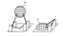
- FIG. 1 is a perspective view of a scale model used in a propagation environment estimation method according to a first embodiment of the present disclosure.
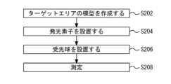
- FIG. 1 is a flowchart for explaining an overview of a propagation environment estimation method according to a first embodiment of the present disclosure.
- 1 is a diagram showing a laser irradiation device according to a first embodiment of the present disclosure; 4 is a flowchart showing an estimation procedure in a propagation environment estimation method according to the first embodiment of the present disclosure.
- FIG. 1 is a first diagram showing a method of installing a laser irradiation device on a scale model.
- FIG. 11 is a second diagram showing a method of installing the laser irradiation device on the scale model.
- FIG. 11 is a third diagram showing a method of installing a laser irradiation device on a scale model.
- 4 is a flowchart showing the entire procedure of a propagation environment estimation method according to the first embodiment.
- 1 is a block diagram showing a configuration of a propagation environment estimation system that performs a series of processes according to a first embodiment of the present disclosure continuously and fully automatically.
- FIG. 11 is a diagram showing a scale model according to a second embodiment of the present disclosure.
- FIG. 11 is a diagram showing a laser irradiation device according to a second embodiment of the present disclosure.
- 13 is a flowchart showing an estimation procedure in a propagation environment estimation method according to a second embodiment of the present disclosure.
- FIG. 11 is a diagram showing details of a laser irradiation device according to a second embodiment of the present disclosure.
- First embodiment [Outline of First Embodiment] 1 is a perspective view of a scale model used in a propagation environment estimation method according to a first embodiment of the present disclosure.
- the left diagram shows a case where a hollow point in the scale model is set as a measurement point of radio waves.
- the right diagram shows a case where a point on the ground surface in the scale model is set as a measurement point of radio waves.
- one possible method is to create a miniature model of an indoor or outdoor target area at an arbitrary scale ratio, scan a directional light-emitting element that represents the transmitter, and estimate the direction of arrival of the radio waves from the position where the light is irradiated onto a sphere installed at the receiving position.
- Figure 1 shows a miniature model that can be used with this method.
- FIG. 2 is a flowchart for explaining an overview of the propagation environment estimation method according to the first embodiment of the present disclosure. As shown in FIG. 2, in the propagation environment estimation method according to the first embodiment of the present disclosure, the propagation environment is estimated in the following procedure.
- a model of the target area is created.
- this model is referred to as a "scale model.”
- a scale model is a reproduction of an actual urban space, for example, at a scale of about 1/100. While FIG. 2 shows an example in which an outdoor space is used as the target area, the interior of a specific building may also be used as the target area.
- a light source is installed to act as a radio wave transmission source.
- a laser irradiation device is used as the light source.
- the laser irradiation device is equipped with a directional light-emitting element.
- a directional light-emitting element is a light-emitting element that emits laser light with excellent linearity, and an example of such a light-emitting element is a laser pointer.
- the laser irradiation device is configured so that irradiation by the directional light-emitting element can be performed in any direction, including the elevation angle direction. Details of the laser irradiation device will be described later.
- the light receiving sphere 50 or 52 is placed so that the measurement point set in the scale model is at its center.
- the light receiving spheres 50 and 52 are made of a material that appropriately reflects laser light so that when the laser light is irradiated, the irradiated point can be identified visually or by an image sensor.
- the light receiving spheres 50 and 52 may be coated with, for example, fluorescent paint so that the irradiated point of the laser light is clear. Note that if the measurement point is in midair, a perfect sphere such as the light receiving sphere 50 is used. On the other hand, if the measurement point is on the ground surface, a hemisphere such as the light receiving sphere 52 is used.
- step 208 the direction from which the light reaching the measurement point, i.e. the center of the light receiving sphere, comes is measured.
- the measurement is performed, for example, by taking photographs from multiple directions.
- the laser light emitted from the light source is reflected by various elements contained in the scale model, and so it can arrive at the measurement point from any direction.
- [Laser irradiation device according to embodiment 1] 3 is a diagram showing a laser irradiation device according to the first embodiment of the present disclosure.
- the laser irradiation device 2a includes a laser pointer 4.
- the laser pointer 4 includes a motor, gears, etc. (not shown), and therefore the irradiation angle can be changed in any direction.
- the laser pointer 4 is installed on a support 6.
- FIG. 4 is a flowchart showing the estimation procedure in the propagation environment estimation method according to the first embodiment of the present disclosure.
- a laser irradiation device is installed on the scale model.
- a method can be considered in which a hole is drilled at the transmission point of the scale model and the laser irradiation device 2a passes through the hole. The method of installing the laser irradiation device 2a will be described later.
- step 102 the elevation and horizontal angles of the laser pointer are changed to emit laser light in any direction.
- This irradiation direction is changed by a motor or gears provided in the laser pointer 4.
- step 104 the direction from which the laser light is coming is measured.
- the first embodiment allows irradiation by a directional light-emitting element such as a laser pointer in any direction, including the elevation direction.
- the laser irradiation device 2a of the first embodiment changes the direction of the laser pointer 4 itself, making it easy to accurately change the direction of the laser light.
- [Measurement method according to the first embodiment] 5 is a first diagram showing a method of installing a laser irradiation device on a scale model.
- a laser irradiation device 2a is installed in a hole opened at a position equivalent to a transmission point on the scale model 100. With this method, since there is no suspended device, measurements can be performed stably.
- FIG. 6 is a second diagram showing a method of installing a laser irradiation device on a scale model.
- the scale model 100a is suspended from the ceiling.
- the laser irradiation device 2a is installed on the ground. This allows the laser irradiation device 2a to operate more stably. For example, even if the size of the laser irradiation device 2a is large, stable measurements can be performed by using this method.
- FIG. 7 is a third diagram showing a method of installing a laser irradiation device on a scale model.
- the scale model 100b is placed on the ground.
- the laser irradiation device 2a is suspended from the ceiling. This makes it possible to perform measurements even if the size of the laser irradiation device 2a is large and the scale model 100b cannot be suspended.
- Fig. 8 is a flowchart showing the entire procedure of the propagation environment estimation method of the first embodiment.
- the procedure shown in Fig. 8 is started at the stage where information collection of the dimensions and locations of buildings and roads, the radio wave reflectance of main points, the frequency of the radio wave to be used, etc. is completed for the actual target area.
- a scale model is created by a 3D printer.
- the 3D printer is provided with scale information for the scale model to be created, and information regarding the dimensions and placement of various structures and other structures that exist in the target area.
- the 3D printer creates a scale model of the target area according to the provided scale.
- the created scale model is then subjected to a reflective treatment in step 116.
- a reflective treatment for example, the walls of the model building are painted or surface treated to match the light reflectance to the radio wave reflectance.
- the reflective treatment in this step may be carried out manually by an operator.
- the painting process may be carried out by a fully automatic painting device that can specify the areas to be painted in three dimensions.
- the surface treatment may be achieved by processing using a 3D printer.
- a light source is installed to resemble a radio wave transmitting station (step 118).
- This light source becomes the laser irradiation device 2a described above.
- the laser irradiation device 2a is installed at a proposed location for the transmitting station in the scale model.
- the laser irradiation device 2a may be installed manually by an operator, or may be installed without human intervention by a fully automated element mounter.
- receiving markers are placed at the measurement points set within the scale model.
- the receiving markers may be placed manually by an operator, or may be placed by a fully automated element mounter without human intervention.
- scanning with the laser pointer begins in step 122.
- various reflected lights are generated in addition to direct light within the scale model. At a certain scanning position, these lights may become laser light that illuminates the receiving marker.
- the scanning direction of the laser pointer is changed manually or automatically, and the state in which the receiving marker is illuminated by laser light is searched for visually or through image processing.
- step 124 the path of the laser light is photographed by a camera.
- the camera photographs are taken through holes in the wall, ceiling, and floor.
- the camera photographs may be taken manually by an operator, or may be taken by a fully automatic photographing device without human intervention.
- the path of the laser light is estimated from the captured image.
- the reflection position is derived by extracting refraction points from the captured image and detecting their positions.
- the number of refraction points is also detected to derive the number of reflections.
- the distance between a refraction point and other refraction points is detected to derive the propagation distance of the path of the laser light.
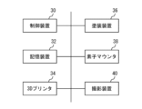
- FIG. 9 is a block diagram showing a configuration of a propagation environment estimation system that performs a series of processes according to the first embodiment of the present disclosure continuously and fully automatically.
- the system shown in Fig. 9 includes a control device 30 and a storage device 32.
- the control device 30 includes an arithmetic processing unit.
- the storage device 32 stores a program executed by the arithmetic processing unit.
- the control device 30 controls each part of the system shown in Fig. 6 by the arithmetic processing unit proceeding with the processes according to the above programs.
- the storage device 32 stores various information related to the target area. This information includes the dimensions, location, and radio wave reflectance of buildings and roads, as well as scale information for the scale model to be created.
- the storage device 32 also stores dimensional data for various elements that can be used in the scale model.
- the storage device 32 also stores the results of measurements performed using the scale model, that is, information on the propagation distance, number of reflections, and reflection position obtained in the processing of step 114 above.
- the system shown in FIG. 9 is equipped with a 3D printer 34.
- the 3D printer 34 reads information about the target area and scale information for the scale model to be created from the storage device 32, and cuts out the scale model. If texture processing is required for specific areas to match the reflectance of the radio waves and the measurement light, this processing is also performed by the 3D printer 34.
- the system shown in FIG. 9 includes a painting device 36.
- the painting device 36 is equipped with a paint nozzle that can move in three dimensions, and can apply the desired paint to any position on the scale model.
- the painting device 36 can apply paint to a specified position on the scale model to obtain the desired reflectance based on information read from the memory device 32.
- the system shown in FIG. 9 includes an element mounter 38.
- the element mounter 38 has the function of installing various elements, etc., planned for use in the scale model, at any position on the scale model.
- the laser irradiation device 2a which functions as a light source
- the receiving marker which is installed at the measurement point, are installed by the element mounter 38 according to the instructions of the control device 30.
- the system shown in FIG. 9 further includes an image capture device 40.
- the image capture device 40 has the function of capturing images of the measurement points set in the scale model from multiple directions.
- the image capture device 40 is configured to capture images of the path of the laser light illuminating the receiving marker from holes opened in the walls, ceiling, and floor of the scale model 100.
- the estimation process in step 126 above is executed by the control device 30 based on the data of the images captured by the image capture device 40.
- the propagation environment estimation method of embodiment 1 makes it possible to provide a propagation environment estimation system that uses a laser irradiation device that can irradiate directional light-emitting elements in any direction, including the elevation angle direction.
- the propagation environment estimation method of this embodiment can be carried out as a fully automatic procedure in a continuous manner. Therefore, according to this system, the work efficiency related to estimating the propagation environment of the target area can be significantly improved.
- the configuration shown in FIG. 9 is described as a system consisting of multiple devices, but the present disclosure is not limited to this.
- the configuration shown in FIG. 9 may be a single device in which the illustrated elements are housed in a single housing.
- Fig. 10 is a diagram showing a scale model according to the second embodiment of the present disclosure.
- Fig. 11 is a diagram showing a laser irradiation device according to the second embodiment of the present disclosure. Numbers enclosed in squares shown in Fig. 10 and Fig. 11 correspond to numbers shown in the flow chart of Fig. 12 described later.
- the second embodiment differs from the first embodiment in the method of changing the direction of laser light in the laser irradiation device.
- the scale model 100 is equipped with a laser irradiation device.
- the laser irradiation device 2b is installed on the scale model. For example, one possible method is to drill a hole at the transmission point of the scale model 100 and pass the laser irradiation device 2b through it.
- the laser irradiation device 2b is equipped with a laser pointer 4.
- the laser pointer 4 irradiates a laser beam through the inside of the support 8.
- the irradiated laser beam is reflected by a reflector 10.
- the reflector 10 can change the reflection angle of the laser beam in any direction by a motor (not shown) or the like equipped in the laser irradiation device 2b.
- FIG. 12 is a flowchart showing the estimation procedure in the propagation environment estimation method according to the second embodiment of the present disclosure.
- a laser irradiation device is installed on the scale model. For example, one possible method is to drill a hole at the transmission point of the scale model and pass the laser irradiation device 2b through it.
- step 108 the laser light is emitted from the bottom of the reflector.
- step 110 the elevation angle and horizontal angle of the reflector 10 are changed to reflect the laser light in any direction.
- step 112 the direction of arrival of the laser light is estimated.
- the laser pointer 4 is embedded inside the scale model, and the direction of the laser light is changed using a reflector 10.
- the laser pointer 4 itself is installed on the scale model. In other words, the second embodiment allows the scale model to be made smaller.
- FIG. 13 is a diagram showing details of a laser irradiation device according to embodiment 2 of the present disclosure. The two figures show the laser irradiation device 2b as viewed from different directions.
- the laser irradiation device 2b is equipped with a laser pointer 4.
- the emitted laser light is reflected by a reflector 10.
- the reflector 10 can perform horizontal angle rotation 12 and elevation angle rotation 14 by a motor or the like provided in the laser irradiation device 2b. Therefore, the laser irradiation device 2b can change the reflection angle of the laser light in any direction.
Landscapes
- Engineering & Computer Science (AREA)
- Computer Networks & Wireless Communication (AREA)
- Signal Processing (AREA)
- Length Measuring Devices By Optical Means (AREA)
Priority Applications (2)
| Application Number | Priority Date | Filing Date | Title |
|---|---|---|---|
| JP2024548931A JPWO2024069818A1 (https=) | 2022-09-28 | 2022-09-28 | |
| PCT/JP2022/036299 WO2024069818A1 (ja) | 2022-09-28 | 2022-09-28 | 伝搬環境推定方法、伝搬環境推定システムおよび伝搬環境推定装置 |
Applications Claiming Priority (1)
| Application Number | Priority Date | Filing Date | Title |
|---|---|---|---|
| PCT/JP2022/036299 WO2024069818A1 (ja) | 2022-09-28 | 2022-09-28 | 伝搬環境推定方法、伝搬環境推定システムおよび伝搬環境推定装置 |
Publications (1)
| Publication Number | Publication Date |
|---|---|
| WO2024069818A1 true WO2024069818A1 (ja) | 2024-04-04 |
Family
ID=90476852
Family Applications (1)
| Application Number | Title | Priority Date | Filing Date |
|---|---|---|---|
| PCT/JP2022/036299 Ceased WO2024069818A1 (ja) | 2022-09-28 | 2022-09-28 | 伝搬環境推定方法、伝搬環境推定システムおよび伝搬環境推定装置 |
Country Status (2)
| Country | Link |
|---|---|
| JP (1) | JPWO2024069818A1 (https=) |
| WO (1) | WO2024069818A1 (https=) |
Citations (2)
| Publication number | Priority date | Publication date | Assignee | Title |
|---|---|---|---|---|
| JP2008256770A (ja) * | 2007-04-02 | 2008-10-23 | Seiko Epson Corp | 走査装置及びそれを用いた投写型表示装置 |
| JP2016057079A (ja) * | 2014-09-05 | 2016-04-21 | 三菱電機株式会社 | モデル化データ算出方法及びモデル化データ算出装置 |
Family Cites Families (5)
| Publication number | Priority date | Publication date | Assignee | Title |
|---|---|---|---|---|
| JP3125289U (ja) * | 2006-07-03 | 2006-09-14 | 株式会社シンプル | マウント用チップledを利用するミニチュアライトキット |
| JP2008054728A (ja) * | 2006-08-29 | 2008-03-13 | Aruze Corp | 遊技機 |
| JP6464213B2 (ja) * | 2017-02-09 | 2019-02-06 | ファナック株式会社 | レーザ加工ヘッドおよび撮影装置を備えるレーザ加工システム |
| CN208860673U (zh) * | 2018-08-22 | 2019-05-14 | 天津大学 | 一种模拟隧道开挖面失稳的透明土试验装置 |
| CN110455489B (zh) * | 2019-08-09 | 2021-03-19 | 东南大学 | 一种测量桥梁节段振动模型表面风压的风洞试验装置 |
-
2022
- 2022-09-28 JP JP2024548931A patent/JPWO2024069818A1/ja active Pending
- 2022-09-28 WO PCT/JP2022/036299 patent/WO2024069818A1/ja not_active Ceased
Patent Citations (2)
| Publication number | Priority date | Publication date | Assignee | Title |
|---|---|---|---|---|
| JP2008256770A (ja) * | 2007-04-02 | 2008-10-23 | Seiko Epson Corp | 走査装置及びそれを用いた投写型表示装置 |
| JP2016057079A (ja) * | 2014-09-05 | 2016-04-21 | 三菱電機株式会社 | モデル化データ算出方法及びモデル化データ算出装置 |
Non-Patent Citations (2)
| Title |
|---|
| LU JONATHAN S.; BERTONI HENRY L.; DEGLI-ESPOSTI VITTORIO: "Scale Model Investigation of Mechanisms for Scattering From Office Buildings at 2 GHz", IEEE TRANSACTIONS ON ANTENNAS AND PROPAGATION, IEEE, USA, vol. 62, no. 12, 1 December 2014 (2014-12-01), USA, pages 6435 - 6442, XP011565520, ISSN: 0018-926X, DOI: 10.1109/TAP.2014.2362115 * |
| RYOTARO TANIGUCHI, TOMOKI MURAKAMI, MINORU INOMATA, TOMOAKI OGAWA, YASUSHI TAKATORI: "MIMO capacity estimation method based on scale model with visible light", IEICE TECHNICAL REPORT, AP, IEICE, JP, vol. 121, no. 330 (AP2021-145), 1 January 2022 (2022-01-01), JP, pages 59 - 63, XP009553840 * |
Also Published As
| Publication number | Publication date |
|---|---|
| JPWO2024069818A1 (https=) | 2024-04-04 |
Similar Documents
| Publication | Publication Date | Title |
|---|---|---|
| CN1273892C (zh) | 有效观察和比较通信网络系统性能的系统和方法 | |
| WO2018229769A1 (en) | Method and system for generating an adaptive projected reality in construction sites | |
| US10997668B1 (en) | Providing shade for optical detection of structural features | |
| JP7281191B2 (ja) | 無線通信評価方法及び評価システム | |
| CN103238080B (zh) | 用于对象的电磁测试的方法和设备 | |
| JP7287034B2 (ja) | 飛翔体、制御方法、及びプログラム | |
| Gutiérrez et al. | A blender-based simulation tool for visible light positioning with portable devices | |
| Alkandari et al. | Optimization of visible light positioning in industrial applications using machine learning | |
| WO2024069818A1 (ja) | 伝搬環境推定方法、伝搬環境推定システムおよび伝搬環境推定装置 | |
| JP7740528B2 (ja) | 伝搬環境推定方法、伝搬環境推定システムおよび伝搬環境推定装置 | |
| CN110347007B (zh) | 一种投影灯中激光器的校准方法和装置 | |
| JP7694714B2 (ja) | 伝搬環境推定方法、伝搬環境推定システムおよび伝搬環境推定装置 | |
| CN114882171A (zh) | 一种基于bim的3d扫描方法、存储介质和计算机设备 | |
| Pendão et al. | Dioptra–A Data Generation Application for Indoor Positioning Systems | |
| JP7747188B2 (ja) | 伝搬環境推定方法、伝搬環境推定システムおよび伝搬環境推定装置 | |
| JP2006163837A (ja) | 避難誘導システム | |
| JP7720001B2 (ja) | 伝搬環境推定方法、伝搬環境推定システムおよび伝搬環境推定装置 | |
| CN116996134A (zh) | 车辆天线性能仿真确定方法、装置、电子设备及存储介质 | |
| US20250052797A1 (en) | Propagation environment estimation method, propagation environment estimation system and propagation environment estimation device | |
| JP2025166676A (ja) | 計測装置及び計測方法 | |
| JP7740570B2 (ja) | 伝搬環境作製装置、伝搬環境作製方法および伝搬環境推定システム | |
| JP2021152309A (ja) | 断熱材の評価方法および断熱材の評価システム | |
| CN115359183B (zh) | 一种三维模型表现装置 | |
| CN119210531B (zh) | 基于非视距微波设备的微波信号传输方法及系统 | |
| TWI817844B (zh) | 場域勘測的方法及系統 |
Legal Events
| Date | Code | Title | Description |
|---|---|---|---|
| 121 | Ep: the epo has been informed by wipo that ep was designated in this application |
Ref document number: 22960880 Country of ref document: EP Kind code of ref document: A1 |
|
| WWE | Wipo information: entry into national phase |
Ref document number: 2024548931 Country of ref document: JP |
|
| NENP | Non-entry into the national phase |
Ref country code: DE |
|
| 122 | Ep: pct application non-entry in european phase |
Ref document number: 22960880 Country of ref document: EP Kind code of ref document: A1 |