WO2024069818A1 - Propagation environment estimating method, propagation environment estimating system, and propagation environment estimating device - Google Patents
Propagation environment estimating method, propagation environment estimating system, and propagation environment estimating device Download PDFInfo
- Publication number
- WO2024069818A1 WO2024069818A1 PCT/JP2022/036299 JP2022036299W WO2024069818A1 WO 2024069818 A1 WO2024069818 A1 WO 2024069818A1 JP 2022036299 W JP2022036299 W JP 2022036299W WO 2024069818 A1 WO2024069818 A1 WO 2024069818A1
- Authority
- WO
- WIPO (PCT)
- Prior art keywords
- scale model
- propagation environment
- laser irradiation
- irradiation device
- light
- Prior art date
Links
- 238000000034 method Methods 0.000 title claims abstract description 64
- 239000003550 marker Substances 0.000 claims abstract description 21
- 238000003384 imaging method Methods 0.000 claims abstract description 15
- 230000005540 biological transmission Effects 0.000 claims description 7
- 238000009434 installation Methods 0.000 claims description 7
- 238000005259 measurement Methods 0.000 description 21
- 238000010586 diagram Methods 0.000 description 18
- 238000012545 processing Methods 0.000 description 9
- 238000004891 communication Methods 0.000 description 4
- 239000003973 paint Substances 0.000 description 4
- 238000010422 painting Methods 0.000 description 4
- 238000005286 illumination Methods 0.000 description 3
- 238000000691 measurement method Methods 0.000 description 3
- 238000011161 development Methods 0.000 description 1
- 239000002360 explosive Substances 0.000 description 1
- 239000000463 material Substances 0.000 description 1
- 238000010295 mobile communication Methods 0.000 description 1
- 238000007591 painting process Methods 0.000 description 1
- 238000004381 surface treatment Methods 0.000 description 1
Images


Classifications
-
- H—ELECTRICITY
- H04—ELECTRIC COMMUNICATION TECHNIQUE
- H04W—WIRELESS COMMUNICATION NETWORKS
- H04W16/00—Network planning, e.g. coverage or traffic planning tools; Network deployment, e.g. resource partitioning or cells structures
- H04W16/18—Network planning tools
Definitions
- This disclosure relates to a propagation environment estimation method, a propagation environment estimation system, and a propagation environment estimation device, and in particular to a propagation environment estimation method, a propagation environment estimation system, and a propagation environment estimation device that are suitable for estimating the environment of a wireless signal using a scale model.
- ITU-R International Telecommunication Union's Radiocommunication Sector
- Non-Patent Document 1 discloses a method for reproducing the propagation loss characteristics in a mobile communications environment using a scale model.
- the propagation environment is estimated by actually measuring the behavior of radio waves in a scale model environment.
- multiple antennas are placed at the measurement points, and the direction of arrival can be estimated by analyzing the phase difference of the radio waves that reach them.
- a method that uses a directional light-emitting element to scan the light, which is treated as a transmitter, is also known as a measurement method that uses a method other than radio waves.
- the direction in which the radio waves arrive can be estimated from the position of the light irradiated onto a sphere placed at the receiving position.
- the directional light-emitting element used in the measurement method described above can only emit the transmission light source in the horizontal direction. In other words, there was an issue that it was not possible to perform measurements that take into account irradiation in the elevation angle direction.
- the first objective of this disclosure is to provide a method for estimating a propagation environment that can provide illumination from directional light-emitting elements in any direction, including the elevation angle, in order to solve the above-mentioned problems.
- a second object of the present disclosure is to provide a propagation environment estimation system that can perform illumination using directional light-emitting elements in any direction, including the elevation angle direction.
- a third object of the present disclosure is to provide a propagation environment estimation device that can perform irradiation with directional light-emitting elements in any direction, including the elevation angle direction.
- the first aspect is a propagation environment estimation method that uses a scale model to estimate the propagation environment of radio waves, and includes a model creation step of creating a scale model, a light source installation step of installing a laser irradiation device having a directional light-emitting element on the scale model to resemble a radio wave transmitting station, a receiving marker installation step of installing a receiving marker on the scale model to resemble a radio wave receiving station, a scanning step of scanning the inside of the scale model with the laser irradiation device, an imaging step of photographing with a camera the path of light when light is irradiated onto the receiving marker, and an estimation step of estimating path propagation information from the image photographed by the camera, and it is preferable that the propagation environment estimation method is such that the laser irradiation device can arbitrarily change the direction of light irradiated by the directional light-emitting element.
- the second aspect is a propagation environment estimation system that uses a scale model to estimate the propagation environment of radio waves, and is preferably a propagation environment estimation system that includes a 3D printer that creates the scale model, an element mounter that installs a laser irradiation device and a receiving marker on the scale model, an imaging device that images the path of light irradiated from the laser irradiation device to the receiving marker, and a control device that controls the 3D printer, the element mounter, and the imaging device, in which the laser irradiation device includes a directional light-emitting element that can change the direction of the light emitted by the directional light-emitting element to any direction, and the control device estimates propagation information of the path from the image acquired by imaging.
- the third aspect is a propagation environment estimation device that estimates the propagation environment of radio waves using a scale model, and is preferably equipped with a 3D printer unit that creates the scale model, an element mounter unit that installs a laser irradiation device and a receiving marker on the scale model, an imaging device unit that images the path of light irradiated from the laser irradiation device to the receiving marker, and a control device unit that controls the 3D printer unit, the element mounter unit, and the imaging device unit, in which the laser irradiation device is equipped with a directional light-emitting element, the direction of the light emitted by the directional light-emitting element can be changed to any direction, and the control device unit estimates propagation information of the path from the image acquired by imaging.
- illumination by the directional light-emitting element can be performed in any direction, including the elevation angle direction.
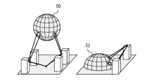
- FIG. 1 is a perspective view of a scale model used in a propagation environment estimation method according to a first embodiment of the present disclosure.
- FIG. 1 is a flowchart for explaining an overview of a propagation environment estimation method according to a first embodiment of the present disclosure.
- 1 is a diagram showing a laser irradiation device according to a first embodiment of the present disclosure; 4 is a flowchart showing an estimation procedure in a propagation environment estimation method according to the first embodiment of the present disclosure.
- FIG. 1 is a first diagram showing a method of installing a laser irradiation device on a scale model.
- FIG. 11 is a second diagram showing a method of installing the laser irradiation device on the scale model.
- FIG. 11 is a third diagram showing a method of installing a laser irradiation device on a scale model.
- 4 is a flowchart showing the entire procedure of a propagation environment estimation method according to the first embodiment.
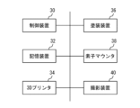
- 1 is a block diagram showing a configuration of a propagation environment estimation system that performs a series of processes according to a first embodiment of the present disclosure continuously and fully automatically.
- FIG. 11 is a diagram showing a scale model according to a second embodiment of the present disclosure.
- FIG. 11 is a diagram showing a laser irradiation device according to a second embodiment of the present disclosure.
- 13 is a flowchart showing an estimation procedure in a propagation environment estimation method according to a second embodiment of the present disclosure.
- FIG. 11 is a diagram showing details of a laser irradiation device according to a second embodiment of the present disclosure.
- First embodiment [Outline of First Embodiment] 1 is a perspective view of a scale model used in a propagation environment estimation method according to a first embodiment of the present disclosure.
- the left diagram shows a case where a hollow point in the scale model is set as a measurement point of radio waves.
- the right diagram shows a case where a point on the ground surface in the scale model is set as a measurement point of radio waves.
- one possible method is to create a miniature model of an indoor or outdoor target area at an arbitrary scale ratio, scan a directional light-emitting element that represents the transmitter, and estimate the direction of arrival of the radio waves from the position where the light is irradiated onto a sphere installed at the receiving position.
- Figure 1 shows a miniature model that can be used with this method.
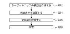
- FIG. 2 is a flowchart for explaining an overview of the propagation environment estimation method according to the first embodiment of the present disclosure. As shown in FIG. 2, in the propagation environment estimation method according to the first embodiment of the present disclosure, the propagation environment is estimated in the following procedure.
- a model of the target area is created.
- this model is referred to as a "scale model.”
- a scale model is a reproduction of an actual urban space, for example, at a scale of about 1/100. While FIG. 2 shows an example in which an outdoor space is used as the target area, the interior of a specific building may also be used as the target area.
- a light source is installed to act as a radio wave transmission source.
- a laser irradiation device is used as the light source.
- the laser irradiation device is equipped with a directional light-emitting element.
- a directional light-emitting element is a light-emitting element that emits laser light with excellent linearity, and an example of such a light-emitting element is a laser pointer.
- the laser irradiation device is configured so that irradiation by the directional light-emitting element can be performed in any direction, including the elevation angle direction. Details of the laser irradiation device will be described later.
- the light receiving sphere 50 or 52 is placed so that the measurement point set in the scale model is at its center.
- the light receiving spheres 50 and 52 are made of a material that appropriately reflects laser light so that when the laser light is irradiated, the irradiated point can be identified visually or by an image sensor.
- the light receiving spheres 50 and 52 may be coated with, for example, fluorescent paint so that the irradiated point of the laser light is clear. Note that if the measurement point is in midair, a perfect sphere such as the light receiving sphere 50 is used. On the other hand, if the measurement point is on the ground surface, a hemisphere such as the light receiving sphere 52 is used.
- step 208 the direction from which the light reaching the measurement point, i.e. the center of the light receiving sphere, comes is measured.
- the measurement is performed, for example, by taking photographs from multiple directions.
- the laser light emitted from the light source is reflected by various elements contained in the scale model, and so it can arrive at the measurement point from any direction.
- [Laser irradiation device according to embodiment 1] 3 is a diagram showing a laser irradiation device according to the first embodiment of the present disclosure.
- the laser irradiation device 2a includes a laser pointer 4.
- the laser pointer 4 includes a motor, gears, etc. (not shown), and therefore the irradiation angle can be changed in any direction.
- the laser pointer 4 is installed on a support 6.
- FIG. 4 is a flowchart showing the estimation procedure in the propagation environment estimation method according to the first embodiment of the present disclosure.
- a laser irradiation device is installed on the scale model.
- a method can be considered in which a hole is drilled at the transmission point of the scale model and the laser irradiation device 2a passes through the hole. The method of installing the laser irradiation device 2a will be described later.
- step 102 the elevation and horizontal angles of the laser pointer are changed to emit laser light in any direction.
- This irradiation direction is changed by a motor or gears provided in the laser pointer 4.
- step 104 the direction from which the laser light is coming is measured.
- the first embodiment allows irradiation by a directional light-emitting element such as a laser pointer in any direction, including the elevation direction.
- the laser irradiation device 2a of the first embodiment changes the direction of the laser pointer 4 itself, making it easy to accurately change the direction of the laser light.
- [Measurement method according to the first embodiment] 5 is a first diagram showing a method of installing a laser irradiation device on a scale model.
- a laser irradiation device 2a is installed in a hole opened at a position equivalent to a transmission point on the scale model 100. With this method, since there is no suspended device, measurements can be performed stably.
- FIG. 6 is a second diagram showing a method of installing a laser irradiation device on a scale model.
- the scale model 100a is suspended from the ceiling.
- the laser irradiation device 2a is installed on the ground. This allows the laser irradiation device 2a to operate more stably. For example, even if the size of the laser irradiation device 2a is large, stable measurements can be performed by using this method.
- FIG. 7 is a third diagram showing a method of installing a laser irradiation device on a scale model.
- the scale model 100b is placed on the ground.
- the laser irradiation device 2a is suspended from the ceiling. This makes it possible to perform measurements even if the size of the laser irradiation device 2a is large and the scale model 100b cannot be suspended.
- Fig. 8 is a flowchart showing the entire procedure of the propagation environment estimation method of the first embodiment.
- the procedure shown in Fig. 8 is started at the stage where information collection of the dimensions and locations of buildings and roads, the radio wave reflectance of main points, the frequency of the radio wave to be used, etc. is completed for the actual target area.
- a scale model is created by a 3D printer.
- the 3D printer is provided with scale information for the scale model to be created, and information regarding the dimensions and placement of various structures and other structures that exist in the target area.
- the 3D printer creates a scale model of the target area according to the provided scale.
- the created scale model is then subjected to a reflective treatment in step 116.
- a reflective treatment for example, the walls of the model building are painted or surface treated to match the light reflectance to the radio wave reflectance.
- the reflective treatment in this step may be carried out manually by an operator.
- the painting process may be carried out by a fully automatic painting device that can specify the areas to be painted in three dimensions.
- the surface treatment may be achieved by processing using a 3D printer.
- a light source is installed to resemble a radio wave transmitting station (step 118).
- This light source becomes the laser irradiation device 2a described above.
- the laser irradiation device 2a is installed at a proposed location for the transmitting station in the scale model.
- the laser irradiation device 2a may be installed manually by an operator, or may be installed without human intervention by a fully automated element mounter.
- receiving markers are placed at the measurement points set within the scale model.
- the receiving markers may be placed manually by an operator, or may be placed by a fully automated element mounter without human intervention.
- scanning with the laser pointer begins in step 122.
- various reflected lights are generated in addition to direct light within the scale model. At a certain scanning position, these lights may become laser light that illuminates the receiving marker.
- the scanning direction of the laser pointer is changed manually or automatically, and the state in which the receiving marker is illuminated by laser light is searched for visually or through image processing.
- step 124 the path of the laser light is photographed by a camera.
- the camera photographs are taken through holes in the wall, ceiling, and floor.
- the camera photographs may be taken manually by an operator, or may be taken by a fully automatic photographing device without human intervention.
- the path of the laser light is estimated from the captured image.
- the reflection position is derived by extracting refraction points from the captured image and detecting their positions.
- the number of refraction points is also detected to derive the number of reflections.
- the distance between a refraction point and other refraction points is detected to derive the propagation distance of the path of the laser light.
- FIG. 9 is a block diagram showing a configuration of a propagation environment estimation system that performs a series of processes according to the first embodiment of the present disclosure continuously and fully automatically.
- the system shown in Fig. 9 includes a control device 30 and a storage device 32.
- the control device 30 includes an arithmetic processing unit.
- the storage device 32 stores a program executed by the arithmetic processing unit.
- the control device 30 controls each part of the system shown in Fig. 6 by the arithmetic processing unit proceeding with the processes according to the above programs.
- the storage device 32 stores various information related to the target area. This information includes the dimensions, location, and radio wave reflectance of buildings and roads, as well as scale information for the scale model to be created.
- the storage device 32 also stores dimensional data for various elements that can be used in the scale model.
- the storage device 32 also stores the results of measurements performed using the scale model, that is, information on the propagation distance, number of reflections, and reflection position obtained in the processing of step 114 above.
- the system shown in FIG. 9 is equipped with a 3D printer 34.
- the 3D printer 34 reads information about the target area and scale information for the scale model to be created from the storage device 32, and cuts out the scale model. If texture processing is required for specific areas to match the reflectance of the radio waves and the measurement light, this processing is also performed by the 3D printer 34.
- the system shown in FIG. 9 includes a painting device 36.
- the painting device 36 is equipped with a paint nozzle that can move in three dimensions, and can apply the desired paint to any position on the scale model.
- the painting device 36 can apply paint to a specified position on the scale model to obtain the desired reflectance based on information read from the memory device 32.
- the system shown in FIG. 9 includes an element mounter 38.
- the element mounter 38 has the function of installing various elements, etc., planned for use in the scale model, at any position on the scale model.
- the laser irradiation device 2a which functions as a light source
- the receiving marker which is installed at the measurement point, are installed by the element mounter 38 according to the instructions of the control device 30.
- the system shown in FIG. 9 further includes an image capture device 40.
- the image capture device 40 has the function of capturing images of the measurement points set in the scale model from multiple directions.
- the image capture device 40 is configured to capture images of the path of the laser light illuminating the receiving marker from holes opened in the walls, ceiling, and floor of the scale model 100.
- the estimation process in step 126 above is executed by the control device 30 based on the data of the images captured by the image capture device 40.
- the propagation environment estimation method of embodiment 1 makes it possible to provide a propagation environment estimation system that uses a laser irradiation device that can irradiate directional light-emitting elements in any direction, including the elevation angle direction.
- the propagation environment estimation method of this embodiment can be carried out as a fully automatic procedure in a continuous manner. Therefore, according to this system, the work efficiency related to estimating the propagation environment of the target area can be significantly improved.
- the configuration shown in FIG. 9 is described as a system consisting of multiple devices, but the present disclosure is not limited to this.
- the configuration shown in FIG. 9 may be a single device in which the illustrated elements are housed in a single housing.
- Fig. 10 is a diagram showing a scale model according to the second embodiment of the present disclosure.
- Fig. 11 is a diagram showing a laser irradiation device according to the second embodiment of the present disclosure. Numbers enclosed in squares shown in Fig. 10 and Fig. 11 correspond to numbers shown in the flow chart of Fig. 12 described later.
- the second embodiment differs from the first embodiment in the method of changing the direction of laser light in the laser irradiation device.
- the scale model 100 is equipped with a laser irradiation device.
- the laser irradiation device 2b is installed on the scale model. For example, one possible method is to drill a hole at the transmission point of the scale model 100 and pass the laser irradiation device 2b through it.
- the laser irradiation device 2b is equipped with a laser pointer 4.
- the laser pointer 4 irradiates a laser beam through the inside of the support 8.
- the irradiated laser beam is reflected by a reflector 10.
- the reflector 10 can change the reflection angle of the laser beam in any direction by a motor (not shown) or the like equipped in the laser irradiation device 2b.
- FIG. 12 is a flowchart showing the estimation procedure in the propagation environment estimation method according to the second embodiment of the present disclosure.
- a laser irradiation device is installed on the scale model. For example, one possible method is to drill a hole at the transmission point of the scale model and pass the laser irradiation device 2b through it.
- step 108 the laser light is emitted from the bottom of the reflector.
- step 110 the elevation angle and horizontal angle of the reflector 10 are changed to reflect the laser light in any direction.
- step 112 the direction of arrival of the laser light is estimated.
- the laser pointer 4 is embedded inside the scale model, and the direction of the laser light is changed using a reflector 10.
- the laser pointer 4 itself is installed on the scale model. In other words, the second embodiment allows the scale model to be made smaller.
- FIG. 13 is a diagram showing details of a laser irradiation device according to embodiment 2 of the present disclosure. The two figures show the laser irradiation device 2b as viewed from different directions.
- the laser irradiation device 2b is equipped with a laser pointer 4.
- the emitted laser light is reflected by a reflector 10.
- the reflector 10 can perform horizontal angle rotation 12 and elevation angle rotation 14 by a motor or the like provided in the laser irradiation device 2b. Therefore, the laser irradiation device 2b can change the reflection angle of the laser light in any direction.
Landscapes
- Engineering & Computer Science (AREA)
- Computer Networks & Wireless Communication (AREA)
- Signal Processing (AREA)
- Length Measuring Devices By Optical Means (AREA)
Abstract
This disclosure relates to a propagation environment estimation method, a propagation environment estimating system, and a propagation environment estimating device suitable for radio signal environment estimation using a scale model. The propagation environment estimating method of the present disclosure uses a scale model to estimate a propagation environment of radio waves. The method includes: a model creating step for creating a scale model; a light source installing step for installing, in the scale model, a laser emitting device provided with a directional light emitting element likened to a radio wave transmitting station; a receiving marker installing step for installing, in the scale model, a receiving marker likened to a radio wave receiving station; a scanning step for scanning the inside of the scale model by using the laser emitting device; an imaging step for imaging, by using a camera, a path of light of when the light is emitted to the receiving marker; and an estimating step for estimating propagation information of the path from the image captured by the camera. The laser emitting device can change, as desired, the direction of the light emitted by the directional light emitting element.
Description
この開示は、伝搬環境推定方法、伝搬環境推定システムおよび伝搬環境推定装置に係り、特に、スケールモデルを利用した無線信号の環境推定に適した伝搬環境推定方法、伝搬環境推定システムおよび伝搬環境推定装置に関する。
This disclosure relates to a propagation environment estimation method, a propagation environment estimation system, and a propagation environment estimation device, and in particular to a propagation environment estimation method, a propagation environment estimation system, and a propagation environment estimation device that are suitable for estimating the environment of a wireless signal using a scale model.
近年では、無線通信デバイスの爆発的な普及に伴って、無線通信に関する需要が高まっている。一方で、無線通信に用い得る周波数資源は限られている。このため、既存の周波数に加えて、これまでは利用されていなかった周波数を利用することが必要となっている。新たな周波数帯を利用するにあたっては、サービスエリアにおける無線信号の伝搬特性や、新たな周波数帯の信号が他のシステムに与える干渉の影響などを事前に調査する必要が生ずる。
In recent years, the demand for wireless communication has increased with the explosive spread of wireless communication devices. At the same time, the frequency resources available for wireless communication are limited. For this reason, it has become necessary to utilize frequencies that have not been used before, in addition to existing frequencies. When using a new frequency band, it becomes necessary to investigate in advance the propagation characteristics of wireless signals in the service area and the impact of interference that signals in the new frequency band may have on other systems.
このような要求の下、例えば、国際電気通信連合(ITU: International Telecommunication Union)の無線通信部門(ITU-R: ITU Radiocommunication Sector)では、実在のエリアで無線信号の伝搬特性を実測し、様々な測定結果から、伝搬モデルを策定する試みがなされている。しかし、この種の試みにおいては、未開拓の周波数についての測定結果が十分でないことや、伝搬モデルが十分に策定されていないことなどが課題となる。
In response to these demands, for example, the International Telecommunication Union's (ITU) Radiocommunication Sector (ITU-R) is attempting to measure the propagation characteristics of wireless signals in real areas and develop propagation models from various measurement results. However, these types of attempts face challenges such as insufficient measurement results for unexplored frequencies and insufficient development of propagation models.
非特許文献1には、スケールモデルを利用して、移動通信環境における伝搬損失の特性を再現する手法が開示されている。この手法では、スケールモデルの環境下で電波の挙動を実測することで伝搬環境を推定する。電波を用いた測定では、例えば、測定点に複数のアンテナを配置して、それらに到達する電波の位相差を解析することで、到来方向が推定できる。
Non-Patent Document 1 discloses a method for reproducing the propagation loss characteristics in a mobile communications environment using a scale model. In this method, the propagation environment is estimated by actually measuring the behavior of radio waves in a scale model environment. In measurements using radio waves, for example, multiple antennas are placed at the measurement points, and the direction of arrival can be estimated by analyzing the phase difference of the radio waves that reach them.
また、電波以外を用いる測定方法として、送信と見立てた有指向性発光素子を走査する方法が知られている。この場合、例えば、受信位置に設置した球体に照射される光の位置から、電波の到来方法を推定できる。
A method that uses a directional light-emitting element to scan the light, which is treated as a transmitter, is also known as a measurement method that uses a method other than radio waves. In this case, for example, the direction in which the radio waves arrive can be estimated from the position of the light irradiated onto a sphere placed at the receiving position.
上述の測定方法で用いる有指向性発光素子は、送信光源を水平方向にしか放射できない。すなわち、仰角方向への照射を考慮した測定を実施できない課題があった。
The directional light-emitting element used in the measurement method described above can only emit the transmission light source in the horizontal direction. In other words, there was an issue that it was not possible to perform measurements that take into account irradiation in the elevation angle direction.
本開示は、上述の課題を解決するため、有指向性発光素子による照射を、仰角方向を含む任意の方向に実施できる伝搬環境推定方法を提供することを第一の目的とする。
The first objective of this disclosure is to provide a method for estimating a propagation environment that can provide illumination from directional light-emitting elements in any direction, including the elevation angle, in order to solve the above-mentioned problems.
また、本開示は、有指向性発光素子による照射を、仰角方向を含む任意の方向に実施できる伝搬環境推定システムを提供することを第二の目的とする。
A second object of the present disclosure is to provide a propagation environment estimation system that can perform illumination using directional light-emitting elements in any direction, including the elevation angle direction.
更に、本開示は、有指向性発光素子による照射を、仰角方向を含む任意の方向に実施できる伝搬環境推定装置を提供することを第三の目的とする。
Furthermore, a third object of the present disclosure is to provide a propagation environment estimation device that can perform irradiation with directional light-emitting elements in any direction, including the elevation angle direction.
第一の態様は、スケールモデルを利用して電波の伝搬環境を推定する伝搬環境推定方法であって、スケールモデルを作成するモデル作成ステップと、スケールモデルに、電波の送信局に見立てて、有指向性発光素子を有するレーザ照射装置を設置する光源設置ステップと、スケールモデルに、電波の受信局に見立てた受信マーカを設置する受信マーカ設置ステップと、レーザ照射装置でスケールモデルの中を走査する走査ステップと、受信マーカに光が照射されたときの光のパスをカメラで撮影する撮影ステップと、カメラで撮影した画像からパスの伝搬情報を推定する推定ステップと、を含み、レーザ照射装置が、有指向性発光素子が照射する光の方向を任意に変更できる伝搬環境推定方法であることが望ましい。
The first aspect is a propagation environment estimation method that uses a scale model to estimate the propagation environment of radio waves, and includes a model creation step of creating a scale model, a light source installation step of installing a laser irradiation device having a directional light-emitting element on the scale model to resemble a radio wave transmitting station, a receiving marker installation step of installing a receiving marker on the scale model to resemble a radio wave receiving station, a scanning step of scanning the inside of the scale model with the laser irradiation device, an imaging step of photographing with a camera the path of light when light is irradiated onto the receiving marker, and an estimation step of estimating path propagation information from the image photographed by the camera, and it is preferable that the propagation environment estimation method is such that the laser irradiation device can arbitrarily change the direction of light irradiated by the directional light-emitting element.
第二の態様は、スケールモデルを利用して電波の伝搬環境を推定する伝搬環境推定システムであって、スケールモデルを作成する3Dプリンタと、スケールモデルに、レーザ照射装置及び受信マーカを設置する素子マウンタと、レーザ照射装置から受信マーカに照射された光のパスを撮影する撮影装置と、3Dプリンタ、素子マウンタ及び撮影装置を制御する制御装置と、を備え、レーザ照射装置が、有指向性発光素子を備え、有指向性発光素子が照射する光の方向を任意の方向に変更でき、制御装置が、撮影で取得した画像からパスの伝搬情報を推定する伝搬環境推定システムであることが望ましい。
The second aspect is a propagation environment estimation system that uses a scale model to estimate the propagation environment of radio waves, and is preferably a propagation environment estimation system that includes a 3D printer that creates the scale model, an element mounter that installs a laser irradiation device and a receiving marker on the scale model, an imaging device that images the path of light irradiated from the laser irradiation device to the receiving marker, and a control device that controls the 3D printer, the element mounter, and the imaging device, in which the laser irradiation device includes a directional light-emitting element that can change the direction of the light emitted by the directional light-emitting element to any direction, and the control device estimates propagation information of the path from the image acquired by imaging.
第三の態様は、スケールモデルを利用して電波の伝搬環境を推定する伝搬環境推定装置であって、スケールモデルを作成する3Dプリンタ部と、スケールモデルに、レーザ照射装置及び受信マーカを設置する素子マウンタ部と、レーザ照射装置から受信マーカに照射された光のパスを撮影する撮影装置部と、3Dプリンタ部、素子マウンタ部及び撮影装置部を制御する制御装置部と、を備え、レーザ照射装置が、有指向性発光素子を備え、有指向性発光素子が照射する光の方向を任意の方向に変更でき、制御装置部が、撮影で取得した画像からパスの伝搬情報を推定する伝搬環境推定装置であることが望ましい。
The third aspect is a propagation environment estimation device that estimates the propagation environment of radio waves using a scale model, and is preferably equipped with a 3D printer unit that creates the scale model, an element mounter unit that installs a laser irradiation device and a receiving marker on the scale model, an imaging device unit that images the path of light irradiated from the laser irradiation device to the receiving marker, and a control device unit that controls the 3D printer unit, the element mounter unit, and the imaging device unit, in which the laser irradiation device is equipped with a directional light-emitting element, the direction of the light emitted by the directional light-emitting element can be changed to any direction, and the control device unit estimates propagation information of the path from the image acquired by imaging.
第1から第3の態様によれば、有指向性発光素子による照射を、仰角方向を含む任意の方向に実施できる。
According to the first to third aspects, illumination by the directional light-emitting element can be performed in any direction, including the elevation angle direction.
実施の形態1
[実施の形態1の概要]
図1は、本開示の実施の形態1に係る伝搬環境推定方法において用いられるスケールモデルの斜視図である。左の図は、スケールモデルにおける中空の点が電波の測定点に設定された場合を示している。また、右の図は、スケールモデルにおける地表の点が電波の測定点に設定された場合を示している。 First embodiment
[Outline of First Embodiment]
1 is a perspective view of a scale model used in a propagation environment estimation method according to a first embodiment of the present disclosure. The left diagram shows a case where a hollow point in the scale model is set as a measurement point of radio waves. The right diagram shows a case where a point on the ground surface in the scale model is set as a measurement point of radio waves.
スケールモデルを用いて伝搬環境推定を行おうとした場合、屋内あるいは屋外のターゲットエリアを任意のスケール率でミニチュアモデル化し、送信と見立てた有指向性発光素子を走査し、受信位置に設置した球体に照射される位置から、電波の到来方向を推定する手法が考えられる。図1は、この手法で用いることができるミニチュアモデルを示す。
When trying to estimate the propagation environment using a scale model, one possible method is to create a miniature model of an indoor or outdoor target area at an arbitrary scale ratio, scan a directional light-emitting element that represents the transmitter, and estimate the direction of arrival of the radio waves from the position where the light is irradiated onto a sphere installed at the receiving position. Figure 1 shows a miniature model that can be used with this method.
図2は、本開示の実施の形態1に係る伝搬環境推定方法の概要を説明するためのフローチャートである。図2に示すように、本開示の実施の形態1に係る伝搬環境推定方法では、以下の手順で伝搬環境の推定が進められる。
FIG. 2 is a flowchart for explaining an overview of the propagation environment estimation method according to the first embodiment of the present disclosure. As shown in FIG. 2, in the propagation environment estimation method according to the first embodiment of the present disclosure, the propagation environment is estimated in the following procedure.
まず、ステップ202で、ターゲットエリアの模型を作成する。以下、この模型を「スケールモデル」と称する。スケールモデルは、例えば1/100程度の縮尺で、実在の都市空間等を再現したものである。図2は、屋外空間をターゲットエリアとした例を示しているが、特定の建物の室内をターゲットエリアとしてもよい。
First, in step 202, a model of the target area is created. Hereinafter, this model is referred to as a "scale model." A scale model is a reproduction of an actual urban space, for example, at a scale of about 1/100. While FIG. 2 shows an example in which an outdoor space is used as the target area, the interior of a specific building may also be used as the target area.
続けて、ステップ204で、電波の送信源に見立てた光源を設置する。光源としては、レーザ照射装置を用いる。レーザ照射装置は、有指向性発光素子を備える。有指向性発光素子は、直進性に優れたレーザ光を発する発光素子であり、レーザポインタ等が例示できる。レーザ照射装置は、有指向性発光素子による照射を、仰角方向を含む任意の方向に実施できるように構成されている。レーザ照射装置についての詳細は後述する。
Next, in step 204, a light source is installed to act as a radio wave transmission source. A laser irradiation device is used as the light source. The laser irradiation device is equipped with a directional light-emitting element. A directional light-emitting element is a light-emitting element that emits laser light with excellent linearity, and an example of such a light-emitting element is a laser pointer. The laser irradiation device is configured so that irradiation by the directional light-emitting element can be performed in any direction, including the elevation angle direction. Details of the laser irradiation device will be described later.
続けて、ステップ206で、スケールモデルにおいて設定された測定点が中心となるように、受光球体50あるいは52を設置する。受光球体50及び52は、レーザ光が照射された場合に、照射点が目視にて、或いは画像センサにて識別できるように、レーザ光を適切に反射する材質で構成されている。受光球体50及び52には、レーザ光の照射点が明りょうになるように、例えば蛍光塗料等が塗布されていてもよい。なお、測定点が中空に存在する場合は、受光球体50のような完全球体が用いられる。一方、測定点が地表に存在する場合は、受光球体52のような半球体が用いられる。
Next, in step 206, the light receiving sphere 50 or 52 is placed so that the measurement point set in the scale model is at its center. The light receiving spheres 50 and 52 are made of a material that appropriately reflects laser light so that when the laser light is irradiated, the irradiated point can be identified visually or by an image sensor. The light receiving spheres 50 and 52 may be coated with, for example, fluorescent paint so that the irradiated point of the laser light is clear. Note that if the measurement point is in midair, a perfect sphere such as the light receiving sphere 50 is used. On the other hand, if the measurement point is on the ground surface, a hemisphere such as the light receiving sphere 52 is used.
続けて、ステップ208で、上記の測定点、つまり受光球体の中心に到達する光が、どのような方向から到来するかが測定される。測定は例えば、複数方向からの写真撮影により行われる。光源から発せられたレーザ光は、スケールモデルに含まれる様々な要素に反射されるため、あらゆる方向から測定点に到来する可能性がある。
Next, in step 208, the direction from which the light reaching the measurement point, i.e. the center of the light receiving sphere, comes is measured. The measurement is performed, for example, by taking photographs from multiple directions. The laser light emitted from the light source is reflected by various elements contained in the scale model, and so it can arrive at the measurement point from any direction.
[実施の形態1に係るレーザ照射装置]
図3は、本開示の実施の形態1に係るレーザ照射装置を示す図である。レーザ照射装置2aは、レーザポインタ4を備える。レーザポインタ4は、図示しないモータあるいはギア等を備えるため、照射角度を任意の方向に変更できる。また、レーザポインタ4は、支柱6の上に設置されている。 [Laser irradiation device according to embodiment 1]
3 is a diagram showing a laser irradiation device according to the first embodiment of the present disclosure. Thelaser irradiation device 2a includes a laser pointer 4. The laser pointer 4 includes a motor, gears, etc. (not shown), and therefore the irradiation angle can be changed in any direction. The laser pointer 4 is installed on a support 6.
図3は、本開示の実施の形態1に係るレーザ照射装置を示す図である。レーザ照射装置2aは、レーザポインタ4を備える。レーザポインタ4は、図示しないモータあるいはギア等を備えるため、照射角度を任意の方向に変更できる。また、レーザポインタ4は、支柱6の上に設置されている。 [Laser irradiation device according to embodiment 1]
3 is a diagram showing a laser irradiation device according to the first embodiment of the present disclosure. The
図4は、本開示の実施の形態1に係る、伝搬環境推定方法における推定手順を示すフローチャートである。まず、ステップ100で、レーザ照射装置をスケールモデルに設置する。例えば、スケールモデルの送信点に穴をあけ、レーザ照射装置2aを通す方法が考えられる。レーザ照射装置2aの設置方法については後述する。
FIG. 4 is a flowchart showing the estimation procedure in the propagation environment estimation method according to the first embodiment of the present disclosure. First, in step 100, a laser irradiation device is installed on the scale model. For example, a method can be considered in which a hole is drilled at the transmission point of the scale model and the laser irradiation device 2a passes through the hole. The method of installing the laser irradiation device 2a will be described later.
次に、ステップ102で、レーザポインタの仰角及び水平角を変更し、任意の方向にレーザ光を放射する。この照射方向は、レーザポインタ4が備えるモータあるいはギア等により変更される。続けて、ステップ104で、レーザ光の到来方向測定を行う。
Next, in step 102, the elevation and horizontal angles of the laser pointer are changed to emit laser light in any direction. This irradiation direction is changed by a motor or gears provided in the laser pointer 4. Then, in step 104, the direction from which the laser light is coming is measured.
実施の形態1の態様により、レーザポインタのような有指向性発光素子による照射を、仰角方向を含む任意の方向に実施できる。また、実施の形態1のレーザ照射装置2aは、レーザポインタ4自体の方向を変更するため、レーザ光の方向変更を正確に行いやすい。
The first embodiment allows irradiation by a directional light-emitting element such as a laser pointer in any direction, including the elevation direction. In addition, the laser irradiation device 2a of the first embodiment changes the direction of the laser pointer 4 itself, making it easy to accurately change the direction of the laser light.
[実施の形態1の測定方法]
図5は、スケールモデルへのレーザ照射装置の設置方法を示す第一の図である。スケールモデル100は、送信点に見立てる位置に開けた穴に、レーザ照射装置2aを設置している。この方法では、吊るされている装置が存在しないため、安定して測定を行うことができる。 [Measurement method according to the first embodiment]
5 is a first diagram showing a method of installing a laser irradiation device on a scale model. Alaser irradiation device 2a is installed in a hole opened at a position equivalent to a transmission point on the scale model 100. With this method, since there is no suspended device, measurements can be performed stably.
図5は、スケールモデルへのレーザ照射装置の設置方法を示す第一の図である。スケールモデル100は、送信点に見立てる位置に開けた穴に、レーザ照射装置2aを設置している。この方法では、吊るされている装置が存在しないため、安定して測定を行うことができる。 [Measurement method according to the first embodiment]
5 is a first diagram showing a method of installing a laser irradiation device on a scale model. A
図6は、スケールモデルへのレーザ照射装置の設置方法を示す第二の図である。スケールモデル100aは、天井から吊り下げられている。そして、レーザ照射装置2aは、地面に設置されている。これにより、レーザ照射装置2aを、より安定して動作させることができる。例えば、レーザ照射装置2aのサイズが大きい場合でも、この方法を用いることで、安定した測定を行うことができる。
FIG. 6 is a second diagram showing a method of installing a laser irradiation device on a scale model. The scale model 100a is suspended from the ceiling. The laser irradiation device 2a is installed on the ground. This allows the laser irradiation device 2a to operate more stably. For example, even if the size of the laser irradiation device 2a is large, stable measurements can be performed by using this method.
図7は、スケールモデルへのレーザ照射装置の設置方法を示す第三の図である。スケールモデル100bは、地面に設置されている。そして、レーザ照射装置2aは、天井から吊り下げられている。これにより、レーザ照射装置2aのサイズが大きく、かつ、スケールモデル100bを吊り下げられない場合でも、測定を実現できる。
FIG. 7 is a third diagram showing a method of installing a laser irradiation device on a scale model. The scale model 100b is placed on the ground. The laser irradiation device 2a is suspended from the ceiling. This makes it possible to perform measurements even if the size of the laser irradiation device 2a is large and the scale model 100b cannot be suspended.
[実施の形態1における手順の詳細]
図8は、実施の形態1の伝搬環境推定方法の全手順を示すフローチャートである。ここでは、レーザ照射装置2aを用いた、伝搬環境推定方法の一例を示す。図8に示す手順は、実在のターゲットエリアについて、建造物や道路の寸法および所在地、主要箇所の電波の反射率、使用予定の電波の周波数などの情報収集が終了した段階で開始される。 [Details of the procedure in the first embodiment]
Fig. 8 is a flowchart showing the entire procedure of the propagation environment estimation method of the first embodiment. Here, an example of the propagation environment estimation method using thelaser irradiation device 2a is shown. The procedure shown in Fig. 8 is started at the stage where information collection of the dimensions and locations of buildings and roads, the radio wave reflectance of main points, the frequency of the radio wave to be used, etc. is completed for the actual target area.
図8は、実施の形態1の伝搬環境推定方法の全手順を示すフローチャートである。ここでは、レーザ照射装置2aを用いた、伝搬環境推定方法の一例を示す。図8に示す手順は、実在のターゲットエリアについて、建造物や道路の寸法および所在地、主要箇所の電波の反射率、使用予定の電波の周波数などの情報収集が終了した段階で開始される。 [Details of the procedure in the first embodiment]
Fig. 8 is a flowchart showing the entire procedure of the propagation environment estimation method of the first embodiment. Here, an example of the propagation environment estimation method using the
図8に示すように、まずステップ114で、3Dプリンタによりスケールモデルが作成される。ここでは、3Dプリンタに、作製するスケールモデルの縮尺情報と、ターゲットエリアに存在する各種建造物等の寸法や配置に関する情報が提供される。3Dプリンタは、提供された縮尺に従って、ターゲットエリアのスケールモデルを作成する。
As shown in FIG. 8, first, in step 114, a scale model is created by a 3D printer. Here, the 3D printer is provided with scale information for the scale model to be created, and information regarding the dimensions and placement of various structures and other structures that exist in the target area. The 3D printer creates a scale model of the target area according to the provided scale.
3Dプリンタの処理が終わると、次に、ステップ116で、作成されたスケールモデルに反射処理が施される。例えば、建造物の模型の壁面に、光の反射率を電波の反射率に合わせるための塗装処理、あるいは表面処理等が施される。本ステップの反射処理は、作業者が手作業により進めてもよい。或いは、塗装処理は、塗装箇所を三次元で指定することのできる全自動の塗装装置により実施してもよい。更に、表面処理は、3Dプリンタによる加工により実現してもよい。
Once the 3D printer processing is complete, the created scale model is then subjected to a reflective treatment in step 116. For example, the walls of the model building are painted or surface treated to match the light reflectance to the radio wave reflectance. The reflective treatment in this step may be carried out manually by an operator. Alternatively, the painting process may be carried out by a fully automatic painting device that can specify the areas to be painted in three dimensions. Furthermore, the surface treatment may be achieved by processing using a 3D printer.
次に、電波の送信局に見立てた光源が設置される(ステップ118)。この光源が、前述したレーザ照射装置2aとなる。レーザ照射装置2aは、スケールモデルにおける送信局の設置候補地に設置される。レーザ照射装置2aの設置は、作業者が手作業により進めても良いし、人手を介さずに、全自動の素子マウンタにより行ってもよい。
Next, a light source is installed to resemble a radio wave transmitting station (step 118). This light source becomes the laser irradiation device 2a described above. The laser irradiation device 2a is installed at a proposed location for the transmitting station in the scale model. The laser irradiation device 2a may be installed manually by an operator, or may be installed without human intervention by a fully automated element mounter.
次に、ステップ120で、スケールモデル内に設定された測定点に受信マーカが配置される。受信マーカの設置は、作業者が手作業により進めても良いし、人手を介さずに、全自動の素子マウンタにより行ってもよい。
Next, in step 120, receiving markers are placed at the measurement points set within the scale model. The receiving markers may be placed manually by an operator, or may be placed by a fully automated element mounter without human intervention.
上記の処理が終わると、ステップ122で、レーザポインタの走査が開始される。レーザポインタの走査方向が変わるに連れて、スケールモデルの中には、直接光に加えて様々な反射光が発生する。それらの光は、ある走査位置において、受信マーカを照らすレーザ光となることがある。本ステップでは、手動または自動でレーザポインタの走査方向を変化させながら、目視または画像処理により受信マーカがレーザ光で照らされる状態が探索される。
Once the above process is completed, scanning with the laser pointer begins in step 122. As the scanning direction of the laser pointer changes, various reflected lights are generated in addition to direct light within the scale model. At a certain scanning position, these lights may become laser light that illuminates the receiving marker. In this step, the scanning direction of the laser pointer is changed manually or automatically, and the state in which the receiving marker is illuminated by laser light is searched for visually or through image processing.
上述の状態の発生が認められたら、ステップ124で、カメラでそのレーザ光のパスを撮影する。カメラの撮影は、壁、天井及び床に開けられた穴から実施する。またカメラの撮影は、作業者が手作業により進めても良いし、人手を介さずに、全自動の撮影装置により行ってもよい。
If the occurrence of the above-mentioned condition is confirmed, in step 124, the path of the laser light is photographed by a camera. The camera photographs are taken through holes in the wall, ceiling, and floor. The camera photographs may be taken manually by an operator, or may be taken by a fully automatic photographing device without human intervention.
次に、ステップ126で、撮影結果からレーザ光のパスが推定される。例えば、撮影した画像から屈折点を抽出し、その位置を検出することで反射位置を導出する。また屈折点の個数を検出することで、反射回数を導出する。さらに、屈折点と他の屈折点の距離を検出することで、レーザ光のパスの伝搬距離を導出する。
Next, in step 126, the path of the laser light is estimated from the captured image. For example, the reflection position is derived by extracting refraction points from the captured image and detecting their positions. The number of refraction points is also detected to derive the number of reflections. Furthermore, the distance between a refraction point and other refraction points is detected to derive the propagation distance of the path of the laser light.
[実施の形態1の伝搬環境推定システム]
図9は、本開示の実施の形態1に係る一連の処理を、連続的に全自動で進める伝搬環境推定システムの構成を示すブロック図である。図9に示すシステムは、制御装置30と記憶装置32を備えている。制御装置30は、演算処理ユニットを備えている。記憶装置32には、演算処理ユニットで実行されるプログラムが格納されている。制御装置30は、演算処理ユニットが上記のプログラムに沿って処理を進めることにより、図6に示すシステムの各部を制御する。 [Propagation Environment Estimation System of the First Embodiment]
Fig. 9 is a block diagram showing a configuration of a propagation environment estimation system that performs a series of processes according to the first embodiment of the present disclosure continuously and fully automatically. The system shown in Fig. 9 includes acontrol device 30 and a storage device 32. The control device 30 includes an arithmetic processing unit. The storage device 32 stores a program executed by the arithmetic processing unit. The control device 30 controls each part of the system shown in Fig. 6 by the arithmetic processing unit proceeding with the processes according to the above programs.
図9は、本開示の実施の形態1に係る一連の処理を、連続的に全自動で進める伝搬環境推定システムの構成を示すブロック図である。図9に示すシステムは、制御装置30と記憶装置32を備えている。制御装置30は、演算処理ユニットを備えている。記憶装置32には、演算処理ユニットで実行されるプログラムが格納されている。制御装置30は、演算処理ユニットが上記のプログラムに沿って処理を進めることにより、図6に示すシステムの各部を制御する。 [Propagation Environment Estimation System of the First Embodiment]
Fig. 9 is a block diagram showing a configuration of a propagation environment estimation system that performs a series of processes according to the first embodiment of the present disclosure continuously and fully automatically. The system shown in Fig. 9 includes a
記憶装置32は、上記のプログラムに加えて、ターゲットエリアに関する各種の情報が格納されている。この情報には、建造物や道路等の寸法、所在値、電波反射率等と、作製するスケールモデルの縮尺情報が含まれている。記憶装置32には、また、スケールモデルで使用可能な各種の素子の寸法データも格納されている。更に、記憶装置32には、スケールモデルを利用して実施される測定の結果、つまり、上記ステップ114の処理で得られる伝搬距離、反射回数、反射位置の情報も格納される。
In addition to the above programs, the storage device 32 stores various information related to the target area. This information includes the dimensions, location, and radio wave reflectance of buildings and roads, as well as scale information for the scale model to be created. The storage device 32 also stores dimensional data for various elements that can be used in the scale model. Furthermore, the storage device 32 also stores the results of measurements performed using the scale model, that is, information on the propagation distance, number of reflections, and reflection position obtained in the processing of step 114 above.
図9に示すシステムは、3Dプリンタ34を備えている。3Dプリンタ34は、ターゲットエリアに関する情報及び作製するスケールモデルの縮尺情報を、記憶装置32から読み出して、スケールモデルの削り出しを行う。電波と測定光の反射率を揃えるために特定の部位にテクスチャ処理を施す必要がある場合は、その処理も3Dプリンタ34が実施する。
The system shown in FIG. 9 is equipped with a 3D printer 34. The 3D printer 34 reads information about the target area and scale information for the scale model to be created from the storage device 32, and cuts out the scale model. If texture processing is required for specific areas to match the reflectance of the radio waves and the measurement light, this processing is also performed by the 3D printer 34.
図9に示すシステムは、塗装装置36を備えている。塗装装置36は、三次元に移動することのできる塗料ノズルを備えており、スケールモデルの任意の位置に、所望の塗料を塗布することができる。塗装装置36は、制御装置30の指令に応じて、記憶装置32から読み出した情報に基づいて、スケールモデルの指定位置に、所望の反射率を得るための塗装を施すことができる。
The system shown in FIG. 9 includes a painting device 36. The painting device 36 is equipped with a paint nozzle that can move in three dimensions, and can apply the desired paint to any position on the scale model. In response to commands from the control device 30, the painting device 36 can apply paint to a specified position on the scale model to obtain the desired reflectance based on information read from the memory device 32.
図9に示すシステムは、素子マウンタ38を備えている。素子マウンタ38は、スケールモデルにおいて使用が予定されている各種の素子等を、スケールモデルの任意の位置に設置する機能を有している。本実施形態では、光源として機能するレーザ照射装置2a、並びに測定点に設置される受信マーカが、制御装置30の指令に従って、素子マウンタ38により設置される。
The system shown in FIG. 9 includes an element mounter 38. The element mounter 38 has the function of installing various elements, etc., planned for use in the scale model, at any position on the scale model. In this embodiment, the laser irradiation device 2a, which functions as a light source, and the receiving marker, which is installed at the measurement point, are installed by the element mounter 38 according to the instructions of the control device 30.
図9に示すシステムは、更に、撮影装置40を備えている。撮影装置40は、スケールモデルの中に設定される測定点を、複数の方向から撮影する機能を有している。本実施形態では、撮影装置40は、受信マーカを照らすレーザ光のパスを、スケールモデル100の壁、天井及び床に開けられた穴から撮影することができるように構成されている。上記ステップ126の推定処理は、撮影装置40が撮影した画像のデータに基づいて、制御装置30により実行される。
The system shown in FIG. 9 further includes an image capture device 40. The image capture device 40 has the function of capturing images of the measurement points set in the scale model from multiple directions. In this embodiment, the image capture device 40 is configured to capture images of the path of the laser light illuminating the receiving marker from holes opened in the walls, ceiling, and floor of the scale model 100. The estimation process in step 126 above is executed by the control device 30 based on the data of the images captured by the image capture device 40.
以上説明した通り、実施の形態1の伝搬環境推定方法によれば、有指向性発光素子による照射を、仰角方向を含む任意の方向に実施できるレーザ照射装置を利用した伝搬環境推定システムを提供することが可能となる。
As described above, the propagation environment estimation method of embodiment 1 makes it possible to provide a propagation environment estimation system that uses a laser irradiation device that can irradiate directional light-emitting elements in any direction, including the elevation angle direction.
また、図9を参照して説明した伝搬環境推定システムによれば、本実施形態の伝搬環境推定方法を、一気通貫で全自動の手順として進行させることができる。このため、このシステムによれば、ターゲットエリアの伝搬環境の推定に関わる作業効率を、著しく改善することができる。
Furthermore, according to the propagation environment estimation system described with reference to FIG. 9, the propagation environment estimation method of this embodiment can be carried out as a fully automatic procedure in a continuous manner. Therefore, according to this system, the work efficiency related to estimating the propagation environment of the target area can be significantly improved.
ところで、上述した実施の形態1では、図9に示す構成を、複数の装置から成るシステムとして説明しているが、本開示はこれに限定されるものではない。すなわち、図9に示す構成は、図示の要素を一台の筐体に収めた一台の装置であってもよい。
In the above-mentioned first embodiment, the configuration shown in FIG. 9 is described as a system consisting of multiple devices, but the present disclosure is not limited to this. In other words, the configuration shown in FIG. 9 may be a single device in which the illustrated elements are housed in a single housing.
実施の形態2の概要
図10は、本開示の実施の形態2に係るスケールモデルを示す図である。また、図11は、本開示の実施の形態2に係るレーザ照射装置を示す図である。また、図10及び図11の図中に示した、四角で囲われた数字は、後述する図12のフローチャート中に示した数字と対応している。実施の形態2は、レーザ照射装置におけるレーザ光の方向変更の方法が、実施の形態1と異なる。 Overview of the Second Embodiment Fig. 10 is a diagram showing a scale model according to the second embodiment of the present disclosure. Fig. 11 is a diagram showing a laser irradiation device according to the second embodiment of the present disclosure. Numbers enclosed in squares shown in Fig. 10 and Fig. 11 correspond to numbers shown in the flow chart of Fig. 12 described later. The second embodiment differs from the first embodiment in the method of changing the direction of laser light in the laser irradiation device.
図10は、本開示の実施の形態2に係るスケールモデルを示す図である。また、図11は、本開示の実施の形態2に係るレーザ照射装置を示す図である。また、図10及び図11の図中に示した、四角で囲われた数字は、後述する図12のフローチャート中に示した数字と対応している。実施の形態2は、レーザ照射装置におけるレーザ光の方向変更の方法が、実施の形態1と異なる。 Overview of the Second Embodiment Fig. 10 is a diagram showing a scale model according to the second embodiment of the present disclosure. Fig. 11 is a diagram showing a laser irradiation device according to the second embodiment of the present disclosure. Numbers enclosed in squares shown in Fig. 10 and Fig. 11 correspond to numbers shown in the flow chart of Fig. 12 described later. The second embodiment differs from the first embodiment in the method of changing the direction of laser light in the laser irradiation device.
スケールモデル100は、レーザ照射装置を備える。レーザ照射装置2bをスケールモデルに設置する。例えば、スケールモデル100の送信点に穴をあけ、レーザ照射装置2bを通す方法が考えられる。
The scale model 100 is equipped with a laser irradiation device. The laser irradiation device 2b is installed on the scale model. For example, one possible method is to drill a hole at the transmission point of the scale model 100 and pass the laser irradiation device 2b through it.
レーザ照射装置2bは、レーザポインタ4を備える。レーザポインタ4は、支柱8の内部を通して、レーザ光を照射する。照射されたレーザ光は、反射板10で反射される。反射板10は、レーザ照射装置2bが備える図示しないモータ等により、レーザ光の反射角度を任意の方向に変更できる。
The laser irradiation device 2b is equipped with a laser pointer 4. The laser pointer 4 irradiates a laser beam through the inside of the support 8. The irradiated laser beam is reflected by a reflector 10. The reflector 10 can change the reflection angle of the laser beam in any direction by a motor (not shown) or the like equipped in the laser irradiation device 2b.
図12は、本開示の実施の形態2に係る、伝搬環境推定方法における推定手順を示すフローチャートである。ステップ106で、レーザ照射装置をスケールモデルに設置する。例えば、スケールモデルの送信点に穴をあけ、レーザ照射装置2bを通す方法が考えられる。
FIG. 12 is a flowchart showing the estimation procedure in the propagation environment estimation method according to the second embodiment of the present disclosure. In step 106, a laser irradiation device is installed on the scale model. For example, one possible method is to drill a hole at the transmission point of the scale model and pass the laser irradiation device 2b through it.
次に、ステップ108で、レーザ光を反射板の下部から放射する。次に、ステップ110で、反射板10の仰角及び水平角を変更し、任意の方向にレーザ光を反射する。続けて、ステップ112で、レーザ光の到来方向推定を行う。
Next, in step 108, the laser light is emitted from the bottom of the reflector. Next, in step 110, the elevation angle and horizontal angle of the reflector 10 are changed to reflect the laser light in any direction. Then, in step 112, the direction of arrival of the laser light is estimated.
実施の形態2では、レーザポインタ4はスケールモデルの内部に埋め込まれ、反射板10を用いてレーザ光の照射方向を変更する。一方、実施の形態1では、レーザポインタ4自体がスケールモデル上に設置されている。すなわち、実施の形態2の方が、スケールモデルを小型化することができる。
In the second embodiment, the laser pointer 4 is embedded inside the scale model, and the direction of the laser light is changed using a reflector 10. On the other hand, in the first embodiment, the laser pointer 4 itself is installed on the scale model. In other words, the second embodiment allows the scale model to be made smaller.
図13は、本開示の実施の形態2に係るレーザ照射装置の詳細を示す図である。2つの図は、レーザ照射装置2bを、異なる方向から見たものである。
FIG. 13 is a diagram showing details of a laser irradiation device according to embodiment 2 of the present disclosure. The two figures show the laser irradiation device 2b as viewed from different directions.
前述の通り、レーザ照射装置2bは、レーザポインタ4を備える。照射されたレーザ光は、反射板10で反射される。反射板10は、レーザ照射装置2bが備えるモータ等により、水平角回転12及び仰角回転14を実施できる。そのため、レーザ照射装置2bは、レーザ光の反射角度を、任意の方向に変更できる。
As described above, the laser irradiation device 2b is equipped with a laser pointer 4. The emitted laser light is reflected by a reflector 10. The reflector 10 can perform horizontal angle rotation 12 and elevation angle rotation 14 by a motor or the like provided in the laser irradiation device 2b. Therefore, the laser irradiation device 2b can change the reflection angle of the laser light in any direction.
2a、2b レーザ照射装置
10 反射板
30 制御装置
38 素子マウンタ
40 撮影装置
100、100a、100b スケールモデル Reference Signs List 2a, 2b Laser irradiation device 10 Reflector 30 Control device 38 Element mounter 40 Photography device 100, 100a, 100b Scale model
10 反射板
30 制御装置
38 素子マウンタ
40 撮影装置
100、100a、100b スケールモデル
Claims (8)
- スケールモデルを利用して電波の伝搬環境を推定する伝搬環境推定方法であって、
スケールモデルを作成するモデル作成ステップと、
前記スケールモデルに、電波の送信局に見立てて、有指向性発光素子を有するレーザ照射装置を設置する光源設置ステップと、
前記スケールモデルに、電波の受信局に見立てた受信マーカを設置する受信マーカ設置ステップと、
前記レーザ照射装置で前記スケールモデルの中を走査する走査ステップと、
前記受信マーカに光が照射されたときの光のパスをカメラで撮影する撮影ステップと、
前記カメラで撮影した画像から前記パスの伝搬情報を推定する推定ステップと、
を含み、
前記レーザ照射装置が、前記有指向性発光素子が照射する光の方向を任意に変更できる
伝搬環境推定方法。 A propagation environment estimation method for estimating a radio wave propagation environment by using a scale model, comprising:
A model making step for making a scale model;
a light source installation step of installing a laser irradiation device having a directional light emitting element on the scale model as if it were a radio wave transmitting station;
a receiving marker installation step of installing a receiving marker representing a radio wave receiving station on the scale model;
a scanning step of scanning the inside of the scale model with the laser irradiation device;
an imaging step of imaging a path of light when the receiving marker is irradiated with light by a camera;
an estimation step of estimating propagation information of the path from an image captured by the camera;
Including,
The laser irradiation device can arbitrarily change the direction of the light emitted by the directional light emitting element. - 前記有指向性発光素子が、モータあるいはギアを備える、請求項1に記載の伝搬環境推定方法。 The propagation environment estimation method according to claim 1, wherein the directional light-emitting element is equipped with a motor or a gear.
- 前記レーザ照射装置が、反射板を備え、
前記反射板が、
モータにより向きを任意の方向に変更でき、
前記有指向性発光素子が照射する光を反射させる
請求項1に記載の伝搬環境推定方法。 The laser irradiation device includes a reflector,
The reflector is
The motor can change the direction to any direction.
The propagation environment estimation method according to claim 1 , wherein the light emitted by the directional light emitting element is reflected. - 前記光源設置ステップが、
前記スケールモデルの、送信点に見立てた穴に、前記レーザ照射装置を設置するステップを含む
請求項1に記載の伝搬環境推定方法。 The light source installation step includes:
The method for estimating a propagation environment according to claim 1 , further comprising the step of: installing the laser irradiation device in a hole in the scale model, the hole representing a transmission point. - 前記光源設置ステップが、
地面に設置した前記レーザ照射装置の上空に、前記スケールモデルを吊り下げるステップを含む
請求項1に記載の伝搬環境推定方法。 The light source installation step includes:
The method of claim 1 , further comprising the step of suspending the scale model above the laser irradiation device that is installed on the ground. - 前記光源設置ステップが、
地面に設置した前記スケールモデルの上空に、前記レーザ照射装置を吊り下げるステップを含む
請求項1に記載の伝搬環境推定方法。 The light source installation step includes:
The method of estimating a propagation environment according to claim 1 , further comprising the step of suspending the laser irradiation device in the air above the scale model placed on the ground. - スケールモデルを利用して電波の伝搬環境を推定する伝搬環境推定システムであって、
スケールモデルを作成する3Dプリンタと、
前記スケールモデルに、レーザ照射装置及び受信マーカを設置する素子マウンタと、
前記レーザ照射装置から前記受信マーカに照射された光のパスを撮影する撮影装置と、
前記3Dプリンタ、前記素子マウンタ及び前記撮影装置を制御する制御装置と、
を備え、
前記レーザ照射装置が、
有指向性発光素子を備え、
前記有指向性発光素子が照射する光の方向を任意の方向に変更でき、
前記制御装置が、前記撮影で取得した画像から前記パスの伝搬情報を推定する
伝搬環境推定システム。 A propagation environment estimation system that estimates a radio wave propagation environment by using a scale model, comprising:
A 3D printer to create scale models,
an element mounter for installing a laser irradiation device and a receiving marker on the scale model;
an imaging device that images a path of light irradiated from the laser irradiation device to the receiving marker;
A control device that controls the 3D printer, the element mounter, and the imaging device;
Equipped with
The laser irradiation device includes:
A directional light emitting element is provided,
The direction of light emitted by the directional light emitting element can be changed to any direction,
the control device estimates propagation information of the path from the image acquired by the photographing. - スケールモデルを利用して電波の伝搬環境を推定する伝搬環境推定装置であって、
スケールモデルを作成する3Dプリンタ部と、
前記スケールモデルに、レーザ照射装置及び受信マーカを設置する素子マウンタ部と、
前記レーザ照射装置から前記受信マーカに照射された光のパスを撮影する撮影装置部と、
前記3Dプリンタ部、前記素子マウンタ部及び前記撮影装置部を制御する制御装置部と、
を備え、
前記レーザ照射装置が、
有指向性発光素子を備え、
前記有指向性発光素子が照射する光の方向を任意の方向に変更でき、
前記制御装置部が、前記撮影で取得した画像から前記パスの伝搬情報を推定する
伝搬環境推定装置。 A propagation environment estimation device that estimates a radio wave propagation environment by using a scale model, comprising:
A 3D printer section for creating scale models,
an element mounter unit for installing a laser irradiation device and a receiving marker on the scale model;
an imaging device unit that images a path of light irradiated from the laser irradiation device to the receiving marker;
A control device unit that controls the 3D printer unit, the element mounter unit, and the imaging device unit;
Equipped with
The laser irradiation device includes:
A directional light emitting element is provided,
The direction of light emitted by the directional light emitting element can be changed to any direction,
The control device estimates propagation information of the path from the image acquired by the photographing.
Priority Applications (1)
| Application Number | Priority Date | Filing Date | Title |
|---|---|---|---|
| PCT/JP2022/036299 WO2024069818A1 (en) | 2022-09-28 | 2022-09-28 | Propagation environment estimating method, propagation environment estimating system, and propagation environment estimating device |
Applications Claiming Priority (1)
| Application Number | Priority Date | Filing Date | Title |
|---|---|---|---|
| PCT/JP2022/036299 WO2024069818A1 (en) | 2022-09-28 | 2022-09-28 | Propagation environment estimating method, propagation environment estimating system, and propagation environment estimating device |
Publications (1)
| Publication Number | Publication Date |
|---|---|
| WO2024069818A1 true WO2024069818A1 (en) | 2024-04-04 |
Family
ID=90476852
Family Applications (1)
| Application Number | Title | Priority Date | Filing Date |
|---|---|---|---|
| PCT/JP2022/036299 WO2024069818A1 (en) | 2022-09-28 | 2022-09-28 | Propagation environment estimating method, propagation environment estimating system, and propagation environment estimating device |
Country Status (1)
| Country | Link |
|---|---|
| WO (1) | WO2024069818A1 (en) |
Citations (2)
| Publication number | Priority date | Publication date | Assignee | Title |
|---|---|---|---|---|
| JP2008256770A (en) * | 2007-04-02 | 2008-10-23 | Seiko Epson Corp | Scanner and projection type display using the same |
| JP2016057079A (en) * | 2014-09-05 | 2016-04-21 | 三菱電機株式会社 | Modeling data calculation method and modeling data calculation device |
-
2022
- 2022-09-28 WO PCT/JP2022/036299 patent/WO2024069818A1/en unknown
Patent Citations (2)
| Publication number | Priority date | Publication date | Assignee | Title |
|---|---|---|---|---|
| JP2008256770A (en) * | 2007-04-02 | 2008-10-23 | Seiko Epson Corp | Scanner and projection type display using the same |
| JP2016057079A (en) * | 2014-09-05 | 2016-04-21 | 三菱電機株式会社 | Modeling data calculation method and modeling data calculation device |
Non-Patent Citations (2)
| Title |
|---|
| LU JONATHAN S.; BERTONI HENRY L.; DEGLI-ESPOSTI VITTORIO: "Scale Model Investigation of Mechanisms for Scattering From Office Buildings at 2 GHz", IEEE TRANSACTIONS ON ANTENNAS AND PROPAGATION, IEEE, USA, vol. 62, no. 12, 1 December 2014 (2014-12-01), USA, pages 6435 - 6442, XP011565520, ISSN: 0018-926X, DOI: 10.1109/TAP.2014.2362115 * |
| RYOTARO TANIGUCHI, TOMOKI MURAKAMI, MINORU INOMATA, TOMOAKI OGAWA, YASUSHI TAKATORI: "MIMO capacity estimation method based on scale model with visible light", IEICE TECHNICAL REPORT, AP, IEICE, JP, vol. 121, no. 330 (AP2021-145), 1 January 2022 (2022-01-01), JP, pages 59 - 63, XP009553840 * |
Similar Documents
| Publication | Publication Date | Title |
|---|---|---|
| CN111033536A (en) | Method and system for generating adaptive projected reality at construction site | |
| CN106595639B (en) | Positioning system and its localization method and device and robot | |
| CN1273892C (en) | System and method for efficiently visualizing and comparing communication network system performance | |
| CN1422503A (en) | Method and apparatus for simulating and planning of wireless position location network | |
| US10997668B1 (en) | Providing shade for optical detection of structural features | |
| WO2024069818A1 (en) | Propagation environment estimating method, propagation environment estimating system, and propagation environment estimating device | |
| Sun et al. | Aim: Acoustic inertial measurement for indoor drone localization and tracking | |
| Neges et al. | Improving indoor location tracking quality for construction and facility management | |
| WO2023203770A1 (en) | Propagation environment estimation method, propagation environment estimation system, and propagation environment estimation device | |
| US10747192B2 (en) | Installation position pointer system | |
| CN110347007B (en) | Method and device for calibrating laser in projection lamp | |
| KR20030048404A (en) | A device and a method for producing information about the properties of an environment | |
| WO2023209778A1 (en) | Propagation environment estimating method, propagation environment estimating system, and propagation environment estimating device | |
| JP2006163837A (en) | Escape guiding system | |
| WO2023119662A1 (en) | Propagation environment estimation method, propagation environment estimation system, and propagation environment estimation device | |
| WO2023119660A1 (en) | Propagation environment estimation method, propagation environment estimation system, and propagation environment estimation device | |
| Gutiérrez et al. | A blender-based simulation tool for visible light positioning with portable devices | |
| JP7403092B2 (en) | Measurement system, measurement method and program | |
| Wahl et al. | WIP: Real-world 3D models derived from mobile mapping for ray launching based propagation loss modeling | |
| Pendão et al. | Dioptra–A Data Generation Application for Indoor Positioning Systems | |
| US11268804B2 (en) | Automatic light position detection system | |
| WO2023119661A1 (en) | Propagation environment estimation method, propagation environment estimation system, and propagation environment estimation device | |
| Zhang et al. | Large-area super-resolution 3D digital maps for indoor and outdoor wireless channel modeling | |
| CN112379384A (en) | Object position determining method and device | |
| JP2018511810A (en) | Infrared positioning node device and infrared positioning node system |
Legal Events
| Date | Code | Title | Description |
|---|---|---|---|
| 121 | Ep: the epo has been informed by wipo that ep was designated in this application |
Ref document number: 22960880 Country of ref document: EP Kind code of ref document: A1 |