WO2024069705A1 - 電力変換装置、モータ駆動装置および冷凍サイクル適用機器 - Google Patents
電力変換装置、モータ駆動装置および冷凍サイクル適用機器 Download PDFInfo
- Publication number
- WO2024069705A1 WO2024069705A1 PCT/JP2022/035728 JP2022035728W WO2024069705A1 WO 2024069705 A1 WO2024069705 A1 WO 2024069705A1 JP 2022035728 W JP2022035728 W JP 2022035728W WO 2024069705 A1 WO2024069705 A1 WO 2024069705A1
- Authority
- WO
- WIPO (PCT)
- Prior art keywords
- command value
- motor
- axis current
- value
- power conversion
- Prior art date
- Legal status (The legal status is an assumption and is not a legal conclusion. Google has not performed a legal analysis and makes no representation as to the accuracy of the status listed.)
- Ceased
Links
Images






Classifications
-
- H—ELECTRICITY
- H02—GENERATION; CONVERSION OR DISTRIBUTION OF ELECTRIC POWER
- H02P—CONTROL OR REGULATION OF ELECTRIC MOTORS, ELECTRIC GENERATORS OR DYNAMO-ELECTRIC CONVERTERS; CONTROLLING TRANSFORMERS, REACTORS OR CHOKE COILS
- H02P21/00—Arrangements or methods for the control of electric machines by vector control, e.g. by control of field orientation
- H02P21/14—Estimation or adaptation of machine parameters, e.g. flux, current or voltage
- H02P21/20—Estimation of torque
-
- H—ELECTRICITY
- H02—GENERATION; CONVERSION OR DISTRIBUTION OF ELECTRIC POWER
- H02P—CONTROL OR REGULATION OF ELECTRIC MOTORS, ELECTRIC GENERATORS OR DYNAMO-ELECTRIC CONVERTERS; CONTROLLING TRANSFORMERS, REACTORS OR CHOKE COILS
- H02P6/00—Arrangements for controlling synchronous motors or other dynamo-electric motors using electronic commutation dependent on the rotor position; Electronic commutators therefor
- H02P6/08—Arrangements for controlling the speed or torque of a single motor
Definitions
- This disclosure relates to a power conversion device that converts AC power into a desired power, a motor drive device, and a refrigeration cycle application device.
- typical fan motor control controls the current flow to match the load torque when the load torque increases so as to follow the speed command.
- Fan motor control in power conversion devices mounted on air conditioners and the like controls the current flow to match the load torque so as to prevent the speed from dropping, that is, to follow the set speed command, even when the load torque becomes larger than expected due to frosting or the like.
- this type of fan motor control is undesirable in terms of comfort and energy saving, because if the load torque becomes larger than expected and an overcurrent occurs due to the large current flow in accordance with the load torque, the fan motor stops operating and cannot continue to operate.
- Patent Document 1 discloses a technique for limiting the input of speed control so that the q-axis current command value does not increase to the limiter value when a torque command value that is greater than the maximum torque that the motor can output is requested.
- the present disclosure has been made in consideration of the above, and aims to obtain a power conversion device that can continue to operate a motor while suppressing a decrease in the motor's rotation speed, even when the load torque of the connected motor increases.
- the power conversion device includes a rectifier that rectifies a first AC power supplied from a commercial power source, a capacitor connected to the output terminal of the rectifier, an inverter connected to both ends of the capacitor that generates a second AC power and outputs it to a motor that drives a load, and a control device that controls the operation of the inverter to control the rotation speed of the motor.
- the control device reduces the speed command value so that the difference between the rotation speed and a speed command value for controlling the rotation speed falls within a specified range.
- the power conversion device disclosed herein has the advantage that it is possible to continue operating a motor while suppressing a decrease in the motor's rotational speed, even when the load torque of the connected motor increases.
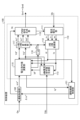
- FIG. 1 is a diagram showing a configuration example of a power conversion device according to a first embodiment
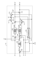
- FIG. 1 is a diagram showing a configuration example of an inverter included in a power conversion device according to a first embodiment
- FIG. 1 is a block diagram showing a configuration example of a control device provided in a power conversion device according to a first embodiment
- FIG. 1 is a block diagram showing an example of the configuration of a voltage command value calculation unit included in a control device for a power conversion device according to a first embodiment
- FIG. 1 is a diagram showing the characteristics of the motor speed and the motor load torque when the power conversion device according to the first embodiment is mounted on a refrigeration cycle application device.
- FIG. 1 is a diagram showing a configuration example of a power conversion device according to a first embodiment
- FIG. 1 is a diagram showing a configuration example of an inverter included in a power conversion device according to a first embodiment
- FIG. 1 is a block diagram showing a configuration example of a control device provided in a
- FIG. 1 is a block diagram showing a configuration example of a continuous operation control unit provided in a control device for a power conversion device according to a first embodiment
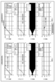
- FIG. 13 is a diagram showing a difference in characteristics depending on whether or not continuous operation control is performed by the continuous operation control unit of the control device provided in the power conversion device according to the first embodiment.
- 1 is a flowchart showing the operation of a power conversion device according to a first embodiment.
- FIG. 1 is a diagram showing an example of a hardware configuration for implementing a control device included in a power conversion device according to a first embodiment
- FIG. 13 is a diagram showing an image of arithmetic processing in a power conversion device according to a third embodiment.
- FIG. 13 is a diagram showing a configuration example of a refrigeration cycle application device according to a fourth embodiment.
- FIG. 1 is a diagram showing a configuration example of a power conversion device 200 according to the first embodiment.
- FIG. 2 is a diagram showing a configuration example of an inverter 30 included in the power conversion device 200 according to the first embodiment.
- the power conversion device 200 is connected to a commercial power source 1 and a motor 7.
- the power conversion device 200 converts a first AC power of a power source voltage Vs supplied from the commercial power source 1 into a second AC power having a desired amplitude and phase, and supplies the second AC power to the motor 7.
- the power conversion device 200 includes a reactor 2, a rectifier 3, a smoothing capacitor 5, an inverter 30, a bus voltage detection unit 10, a load current detection unit 40, and a control device 100.
- the power conversion device 200 and the motor 7 constitute a motor drive device 400.
- the power conversion device 200, the motor 7, the outdoor fan 914, the outdoor heat exchanger 910, and the control unit 920 constitute a refrigeration cycle application device 900.
- the outdoor heat exchanger 910 exchanges heat between a refrigerant flowing therethrough and the outside air.
- the outdoor fan 914 sends air to the outdoor heat exchanger 910.
- the motor 7 drives and rotates the outdoor fan 914.
- Fig. 1 only the configuration of the refrigeration cycle application equipment 900 that is necessary for explaining the power conversion device 200 is shown. The detailed configuration of the refrigeration cycle application equipment 900 will be explained in the fourth embodiment.
- the reactor 2 is connected between the commercial power supply 1 and the rectifier 3.
- the rectifier 3 has a bridge circuit formed by rectifier elements 131 to 134, and rectifies and outputs the first AC power of the power supply voltage Vs supplied from the commercial power supply 1.
- the rectifier 3 performs full-wave rectification.
- the smoothing capacitor 5 is connected to the output terminal of the rectifier 3 and is a smoothing element that smoothes the power rectified by the rectifier 3.
- the smoothing capacitor 5 is, for example, an electrolytic capacitor, a film capacitor, or other capacitor.
- the smoothing capacitor 5 has a capacity to smooth the power rectified by the rectifier 3, and the voltage generated in the smoothing capacitor 5 by the smoothing is not a full-wave rectified waveform of the commercial power source 1, but a waveform in which a voltage ripple according to the frequency of the commercial power source 1 is superimposed on a DC component, and does not pulsate significantly.
- the frequency of this voltage ripple is twice the frequency of the power source voltage Vs when the commercial power source 1 is single-phase, and is mainly six times the frequency when the commercial power source 1 is three-phase.
- the bus voltage detection unit 10 is a detection unit that detects the voltage across the smoothing capacitor 5, i.e., the voltage between the DC buses 12a and 12b, as the bus voltage Vdc, and outputs the detected voltage value to the control device 100.
- the load current detection unit 40 is a detection unit that detects the load current Idc, which is a DC current flowing from the smoothing capacitor 5 to the inverter 30, and outputs the detected current value to the control device 100.
- the inverter 30 is connected to both ends of the smoothing capacitor 5, and converts the power output from the rectifier 3 and the smoothing capacitor 5 into a second AC power having a desired amplitude and phase, i.e., generates the second AC power and outputs it to the motor 7 that drives the load.
- the inverter 30 receives the bus voltage Vdc, generates a three-phase AC voltage with a variable frequency and voltage value, and supplies it to the motor 7 via output lines 331-333.
- the inverter 30 includes an inverter main circuit 310 and a drive circuit 350.
- the input terminals of the inverter main circuit 310 are connected to the DC buses 12a and 12b.
- the inverter main circuit 310 includes switching elements 311-316. Rectifier elements 321-326 for return current are connected in inverse parallel to each of the switching elements 311-316.
- the drive circuit 350 generates drive signals Sr1 to Sr6 based on PWM (Pulse Width Modulation) signals Sm1 to Sm6 output from the control device 100.
- the drive circuit 350 controls the on/off of the switching elements 311 to 316 using the drive signals Sr1 to Sr6. This enables the inverter 30 to supply a three-phase AC voltage with variable frequency and voltage to the motor 7 via the output lines 331 to 333.
- PWM signals Sm1 to Sm6 are signals with a logic circuit signal level, i.e., a magnitude of 0V to 5V.
- PWM signals Sm1 to Sm6 are signals with the ground potential of control device 100 as a reference potential.
- drive signals Sr1 to Sr6 are signals with a voltage level required to control switching elements 311 to 316, for example, a magnitude of -15V to +15V.
- Drive signals Sr1 to Sr6 are signals with a reference potential that is the potential of the negative terminal, i.e., the emitter terminal, of the corresponding switching elements 311 to 316.
- the motor 7 rotates according to the amplitude and phase of the second AC power supplied from the inverter 30.
- the motor 7 is used, for example, for the compression operation of the compressor and the rotation operation of the fan.
- the motor 7 drives and rotates the outdoor fan 914 provided in the refrigeration cycle application device 900 as the load described above, and sends air to the outdoor heat exchanger 910 to cool the outdoor heat exchanger 910.
- FIG. 1 shows the motor 7 with a Y-connection as the motor winding, this is just an example and is not limiting.
- the motor winding of the motor 7 may be a ⁇ -connection, or may be a specification that allows switching between a Y-connection and a ⁇ -connection.
- the arrangement of each component shown in FIG. 1 is one example, and the arrangement of each component is not limited to the example shown in FIG. 1.
- the reactor 2 may be arranged after the rectifier 3.
- the power conversion device 200 may include a boost unit, or the rectifier 3 may be given the function of a boost unit.
- the bus voltage detection unit 10 and the load current detection unit 40 may be collectively referred to as the detection unit.
- the voltage value detected by the bus voltage detection unit 10 and the current value detected by the load current detection unit 40 may be referred to as the detection value.
- the control device 100 obtains the bus voltage Vdc from the bus voltage detection unit 10 and the load current Idc from the load current detection unit 40.
- the control device 100 uses the detection values detected by each detection unit to control the operation of the inverter main circuit 310, specifically, the on/off of the switching elements 311 to 316 of the inverter main circuit 310.
- the control device 100 controls the rotation speed of the motor 7 by controlling the on/off of the switching elements 311 to 316 of the inverter main circuit 310.
- the rotation speed of the motor 7 may be expressed as the rotation speed of the motor 7.
- the control device 100 also calculates the load torque of the motor 7.
- the control device 100 does not need to use all the detection values obtained from each detection unit, and may perform control using some of the detection values. In this embodiment, the control device 100 performs control in a rotating coordinate system having a d-axis and a q-axis.
- FIG. 3 is a block diagram showing an example of the configuration of the control device 100 provided in the power conversion device 200 according to the first embodiment.
- the control device 100 includes an operation control unit 102, an inverter control unit 110, and an operation continuation control unit 121.
- the operation control unit 102 acquires command information Qe from the control unit 920 of the refrigeration cycle application device 900.
- the command information Qe is information based on, for example, a temperature detected by a temperature sensor (not shown), information indicating a set temperature instructed from a remote control (not shown), which is an operation unit, selection information of an operation mode, and instruction information for starting and ending operation.
- the operation mode is, for example, heating, cooling, dehumidification, etc.
- the operation control unit 102 also acquires a speed command reduction amount ⁇ * from the operation continuation control unit 121.
- the operation control unit 102 generates a frequency command value ⁇ e* for generating a voltage command value, which is a command value of a voltage to be applied to the motor 7, based on the command information Qe and the speed command reduction amount ⁇ * .
- the operation control unit 102 can obtain the frequency command value ⁇ e * by subtracting the speed command reduction amount ⁇ * from a value obtained by multiplying a rotational angular velocity command value ⁇ m *, which is a command value of the rotational speed of the motor 7, by the number of pole pairs Pm of the motor 7.
- the operation control unit 102 Based on the command information Qe, the operation control unit 102 generates a stop signal St which is a signal for stopping the operation of the inverter 30.
- the operation control unit 102 outputs the frequency command value ⁇ e * to the voltage command value calculation unit 115 of the inverter control unit 110, and outputs the stop signal St to the PWM signal generation unit 118 of the inverter control unit 110.
- the inverter control unit 110 includes a current restoration unit 111, a three-phase to two-phase conversion unit 112, a d-axis current command value generation unit 113, a voltage command value calculation unit 115, an electrical phase calculation unit 116, a two-phase to three-phase conversion unit 117, and a PWM signal generation unit 118.
- the current restoration unit 111 restores the phase currents iu, iv, and iw flowing through the motor 7 based on the load current Idc detected by the load current detection unit 40.
- the current restoration unit 111 can restore the phase currents iu, iv, and iw by sampling the load current Idc detected by the load current detection unit 40 at timing determined based on the PWM signals Sm1 to Sm6 generated by the PWM signal generation unit 118.
- the three-phase to two-phase conversion unit 112 converts the phase currents iu, iv, and iw restored by the current restoration unit 111 into a d-axis current id, which is an excitation current, and a q-axis current iq, which is a torque current, i.e., the current values of the d and q axes, using the electrical phase ⁇ e generated by the electrical phase calculation unit 116 described below.
- the d-axis current command value generating unit 113 generates a d-axis current command value Id * in the above-mentioned rotating coordinate system. Specifically, the d-axis current command value generating unit 113 obtains an optimal d-axis current command value Id* that is most efficient for driving the motor 7 based on the q-axis current iq, the bus voltage Vdc, the d-axis voltage command value Vd * , and the q-axis voltage command value Vq * .
- the d-axis current command value generating unit 113 outputs a d-axis current command value Id * that is a current phase ⁇ m at which the output torque of the motor 7 is equal to or greater than a specified value or is maximized, that is, the current value is equal to or less than a specified value or is minimized, based on the q-axis current iq , the bus voltage Vdc, the d-axis voltage command value Vd*, and the q-axis voltage command value Vq*.
- the d-axis current command value generating unit 113 obtains the d-axis current command value Id * based on the q-axis current iq , etc., but this is just an example and is not limited to this.
- the d-axis current command value generating unit 113 can obtain the same effect even if it determines the d-axis current command value Id * based on the d-axis current id, the frequency command value ⁇ e * , etc.
- the d-axis current command value generating unit 113 may determine the d-axis current command value Id * by flux-weakening control or the like.
- the voltage command value calculation unit 115 generates a d-axis voltage command value Vd * and a q-axis voltage command value Vq* based on the frequency command value ⁇ e * acquired from the operation control unit 102, the d-axis current id and the q-axis current iq acquired from the three-phase to two-phase conversion unit 112, and the d-axis current command value Id* acquired from the d-axis current command value generation unit 113. In addition, the voltage command value calculation unit 115 generates a q-axis current command value Iq* in the process of generating the d-axis voltage command value Vd * and the q-axis voltage command value Vq * .
- the voltage command value calculation unit 115 estimates a frequency estimated value ⁇ est based on the d-axis voltage command value Vd * , the q-axis voltage command value Vq * , the d-axis current id, and the q-axis current iq.
- the electrical phase calculation unit 116 calculates the electrical phase ⁇ e by integrating the frequency estimate ⁇ est obtained from the voltage command value calculation unit 115.
- the two-phase to three-phase conversion unit 117 converts the d-axis voltage command value Vd * and q-axis voltage command value Vq * obtained from the voltage command value calculation unit 115, i.e., the voltage command values in the two-phase coordinate system, into three-phase voltage command values Vu * , Vv * , Vw * , which are output voltage command values in the three-phase coordinate system, using the electrical phase ⁇ e obtained from the electrical phase calculation unit 116.
- the PWM signal generating unit 118 generates the PWM signals Sm1 to Sm6 based on the three-phase voltage command values Vu * , Vv * , Vw * acquired from the two-phase to three-phase conversion unit 117 and the stop signal St acquired from the operation control unit 102.
- the PWM signal generating unit 118 can also stop the motor 7 by not outputting the PWM signals Sm1 to Sm6 based on the stop signal St.
- FIG. 4 is a block diagram showing an example of the configuration of the voltage command value calculation unit 115 provided in the control device 100 of the power conversion device 200 according to the first embodiment.
- the voltage command value calculation unit 115 includes a frequency estimation unit 501, addition/subtraction units 502, 504, 505, 509, and 513, a speed control unit 503, a d-axis current control unit 506, a q-axis current control unit 507, multiplication units 508, 510, and 512, and an addition unit 511.
- a frequency estimation unit 501 estimates the frequency of the voltage supplied to the motor 7 based on the d-axis current id, the q-axis current iq, the d-axis voltage command value Vd * , and the q-axis voltage command value Vq * , and outputs the frequency estimation value ⁇ est.
- the frequency estimation value ⁇ est output from the frequency estimation unit 501 to the outside of the voltage command value calculation unit 115 in Fig. 4 is the frequency estimation value ⁇ est output from the voltage command value calculation unit 115 to the electrical phase calculation unit 116 in Fig. 3.
- An addition and subtraction unit 502 subtracts the frequency estimation value ⁇ est from the frequency command value ⁇ e * , and outputs a frequency deviation del_ ⁇ between the frequency command value ⁇ e * and the frequency estimation value ⁇ est.
- the speed control unit 503 calculates and outputs a q-axis current command value Iq * based on the frequency deviation del_ ⁇ .
- the q-axis current command value Iq * is a command value of the q-axis current iq at which the frequency deviation del_ ⁇ becomes zero, that is, a command value of the q-axis current iq for making the frequency command value ⁇ e * and the frequency estimated value ⁇ est coincide with each other.
- the speed control unit 503 is, for example, a proportional-integral (PI) controller, but is not limited to this.
- the speed control unit 503 outputs the q-axis current command value Iq * to the adder-subtractor unit 505 in the subsequent stage and also to the operation continuation control unit 121.
- the adder/subtracter 504 subtracts the d-axis current id from the d-axis current command value Id * and outputs the deviation between the d-axis current command value Id * and the d-axis current id.
- the d-axis current control unit 506 is, for example, configured with a PI controller, and operates to converge the deviation between the d-axis current command value Id * and the d-axis current id to zero.
- the d-axis current control unit 506 outputs a first d-axis voltage command value Vdfb * .
- the adder/subtracter 505 subtracts the q-axis current iq from the q-axis current command value Iq * and outputs the deviation between the q-axis current command value Iq * and the q-axis current iq.
- the q-axis current control unit 507 is, for example, configured with a PI controller, and operates to converge the deviation between the q-axis current command value Iq * and the q-axis current iq to zero.
- the q-axis current control unit 507 outputs a first q-axis voltage command value Vqfb * .
- the multiplier 508 multiplies the q-axis current command value Iq * by the q-axis inductance Lq of the motor 7 and the frequency estimate value ⁇ est to calculate and output a compensation value Vdff * of the first d-axis voltage command value Vdfb * .
- the adder/subtracter 509 subtracts the compensation value Vdff * from the first d-axis voltage command value Vdfb * and outputs a second d-axis voltage command value which is the deviation (Vdfb * -Vdff * ) between the first d-axis voltage command value Vdfb * and the compensation value Vdff * as the d-axis voltage command value Vd * from the voltage command value calculator 115.
- the multiplier 510 multiplies the d-axis current command value Id * by the d-axis inductance Ld of the motor 7 and outputs the result.
- the adder 511 adds the magnetic flux linkage vector ⁇ f of the motor 7 to the output from the multiplier 510.
- the multiplier 512 multiplies the output from the adder 511 by the frequency estimate value ⁇ est to calculate and output a compensation value Vqff * of the first q-axis voltage command value Vqfb * .
- the adder/subtracter 513 subtracts the compensation value Vqff* from the first q-axis voltage command value Vqfb * and outputs a second q-axis voltage command value, which is the deviation (Vqfb * -Vqff * ) between the first q-axis voltage command value Vqfb* and the compensation value Vqff * , as the q-axis voltage command value Vq * from the voltage command value calculator 115.
- the operation continuation control unit 121 calculates a speed command reduction amount ⁇ * based on the d-axis current id acquired from the three-phase to two-phase conversion unit 112 and the q-axis current command value Iq * acquired from the voltage command value calculation unit 115.
- the operation continuation control unit 121 outputs the calculated speed command reduction amount ⁇ * to the operation control unit 102.
- the control device 100 controls the speed command value to be reduced so that the difference between the rotation speed and the speed command value for controlling the rotation speed is within a specified range.
- the control device 100 controls the motor 7 to rotate at a reduced rotation speed in a frosted state with a load torque equivalent to the load torque that can be output in a frost-free state.
- the control device 100 can calculate the load torque, i.e., the estimated load torque Tm, using the current value detected by the load current detection unit 40 and parameters based on the specifications of the motor 7. Specifically, the control device 100 estimates the load torque of the motor 7, i.e., calculates the estimated load torque Tm of the motor 7, using the d-axis current id and q-axis current iq output from the three-phase to two-phase conversion unit 112. The control device 100 calculates the estimated load torque Tm of the motor 7 based on the following equation (1).
- Tm Pm ⁇ aiq + Pm(Ld-Lq)idiq ... (1)
- Tm is the estimated load torque
- Pm is the number of pole pairs of the motor 7
- ⁇ a is the induced voltage constant of the motor 7
- Ld is the d-axis inductance of the motor 7
- Lq is the q-axis inductance of the motor 7
- id is the d-axis current
- iq is the q-axis current.
- the control device 100 obtains the d-axis current id and the q-axis current iq from the three-phase to two-phase conversion unit 112, but stores the number of pole pairs Pm of the motor 7, the induced voltage constant ⁇ a of the motor 7, the d-axis inductance Ld of the motor 7, and the q-axis inductance Lq of the motor 7 in advance.
- FIG. 5 is a diagram showing the characteristics of the rotation speed of the motor 7 and the load torque of the motor 7 when the power conversion device 200 according to embodiment 1 is mounted on the refrigeration cycle application device 900.
- the horizontal axis indicates the rotation speed of the motor 7
- the vertical axis indicates the load torque of the motor 7.
- the solid line on which circles are plotted indicates a polynomial that represents a state when frost does not occur in the refrigeration cycle application device 900
- the dashed line on which squares are plotted indicates a polynomial that represents a state when frost occurs in the refrigeration cycle application device 900.
- the rotation speed of the motor 7 on the horizontal axis may be the rotation speed of the outdoor fan 914.
- the load torque is larger when frost occurs in the refrigeration cycle application device 900 than when frost does not occur in the refrigeration cycle application device 900.
- the higher the rotation speed of the motor 7, the larger the difference between the load torque when frost has formed in the refrigeration cycle application device 900 and the load torque when frost has not formed in the refrigeration cycle application device 900.
- the control device 100 reduces the rotation speed of the motor 7 to about 1400 rpm, thereby making it possible to keep the output load torque at the same level while continuing the rotation, i.e., operation, of the motor 7.
- FIG. 6 is a block diagram showing an example of the configuration of the operation continuation control unit 121 provided in the control device 100 of the power conversion device 200 according to embodiment 1.
- the operation continuation control unit 121 includes a limiter value calculation unit 141, an addition/subtraction unit 142, a deviation code processing unit 143, and an output unit 144.
- the limiter value calculation unit 141 uses the d-axis current id acquired from the three-phase to two-phase conversion unit 112 to calculate a limiter value to be compared with the q-axis current command value iq * in the addition/subtraction unit 142.
- the limiter value calculation unit 141 calculates the limiter value iq_lim based on the following equation (2).
- iq_lim ⁇ (3Ie 2 - id 2 ) ... (2)
- iq_lim is a limiter value
- Ie is a limiter value of the effective value of the phase current
- id is a d-axis current indicating the current d-axis current value obtainable from the 3-phase to 2-phase conversion unit 112.
- ⁇ (3Ie 2 - id 2 ) represents the square root of (3Ie 2 - id 2 ).
- the limiter value iq_lim indicates the magnitude of a current that can be circulated as the q-axis current iq, which is the remainder obtained by subtracting the d-axis current id from the limiter value Ie of the effective value of the phase current, in order to preferentially pass the d-axis current id.
- the limiter value calculation unit 141 outputs the limiter value iq_lim calculated by calculation to the addition and subtraction unit 142.
- the adding/subtracting unit 142 obtains the limiter value iq_lim from the limiter value calculation unit 141, and obtains the q-axis current command value iq * from the voltage command value calculation unit 115.
- the adding/subtracting unit 142 calculates the deviation between the limiter value iq_lim and the q-axis current command value iq * by subtracting the q-axis current command value iq * from the limiter value iq_lim.
- the adding/subtracting unit 142 outputs the deviation between the limiter value iq_lim and the q-axis current command value iq * obtained by the calculation to the deviation sign processing unit 143.
- the deviation sign processing unit 143 When the deviation between the limiter value iq_lim and the q-axis current command value iq * is less than 0, i.e., when the q-axis current command value iq * is greater than the limiter value iq_lim, the deviation sign processing unit 143 performs control so that a value obtained by performing integral control on the deviation between the limiter value iq_lim and the q-axis current command value iq * using K Iac /S is output as the speed command decrease amount ⁇ * from the output unit 144.
- K Iac is the integral gain of the integral control
- S in the denominator of K Iac /S represents the Laplace operator.
- the control device 100 reduces the q-axis current command value Iq * by an amount that the q-axis current command value Iq * exceeds the limiter value iq_lim, which is the q-axis current limiter value of the q-axis current command value Iq * , which is the speed command value.
- the control device 100 sets the limiter value iq_lim, which is the q-axis current limiter value, based on the limiter value Ie of the effective value of the phase current, which is the current of each phase flowing from the power conversion device 200 to the motor 7, and the d-axis current id, which is the current d-axis current value.
- the control device 100 can keep the output load torque at the same level by setting the rotation speed of the motor 7 to about 1400 rpm, thereby allowing the motor 7 to continue rotating, i.e., to continue operating. In other words, even if an event occurs in which the load torque of the motor 7 becomes large, the control device 100 controls the rotation of the motor 7 while maintaining the maximum current in the power conversion device 200 by controlling the rotation speed of the motor 7 to be reduced by the amount that exceeds the limiter value iq_lim.
- the method by which the limiter value calculation unit 141 calculates the limiter value iq_lim is not limited to the example of equation (2). As long as the rotation of the motor 7 can be controlled while maintaining the maximum current in the power conversion device 200, the limiter value iq_lim calculated by the limiter value calculation unit 141 may be calculated by another method. For example, the limiter value calculation unit 141 may calculate the limiter value iq_lim from the perspective of voltage saturation.
- FIG. 7 is a diagram showing the difference in characteristics depending on whether or not the control of continuous operation is performed by the operation continuation control unit 121 of the control device 100 provided in the power conversion device 200 according to the first embodiment.
- the left side shows the case where the operation continuation control by the operation continuation control unit 121 is not performed
- the right side shows the case where the operation continuation control by the operation continuation control unit 121 is performed.
- the first row of FIG. 7 shows the rotation speed of the motor 7
- the second row of FIG. 7 shows the torque of the motor 7
- the third row of FIG. 7 shows the phase currents iu, iv, and iw of the motor 7, and the fourth row of FIG.
- the first graph on the left side of FIG. 7 shows a state where the command value and the estimated speed and actual speed are separated. This shows a state where the power conversion device 200 tries to rotate the motor 7 with constant torque control or maximum torque, but the torque required to rotate the motor 7 increases due to the effects of frosting, etc., and the desired rotation speed, i.e., the rotation speed indicated by the command value, cannot be achieved. If the command value and the estimated speed and actual speed continue to diverge, the control is likely to become unstable, such as causing a wind-up phenomenon, which is not preferable for control by the control device 100.
- the command value decreases after a specified time has elapsed since the start of continuous operation control, and the state where the command value and the estimated speed and actual speed are separated is resolved in the first graph on the right side of FIG. 7. This allows the control device 100 to avoid a situation where the command value and the estimated speed and actual speed continue to diverge, and to achieve a stable control state.
- FIG. 8 is a flowchart showing the operation of the power conversion device 200 according to the first embodiment.
- the operation continuation control unit 121 of the control device 100 calculates a limiter value iq_lim for the q-axis current command value Iq* (step S1).
- the operation continuation control unit 121 calculates the deviation between the limiter value iq_lim and the q-axis current command value iq * acquired from the voltage command value calculation unit 115 (step S2).
- the operation continuation control unit 121 outputs a value obtained by performing integral control of the deviation between the limiter value iq_lim and the q-axis current command value iq * using K Iac /S as the speed command reduction amount ⁇ * to the operation control unit 102 (step S5).
- the case where the q-axis current command value Iq * is limited by the limiter value iq_lim in the operation continuation control unit 121 of the control device 100 includes, but is not limited to, the case where the load torque of the motor 7 simply increases and the q-axis current command value Iq * is limited by the limiter value iq_lim, as described above.
- the case where the q-axis current command value Iq * is limited by the limiter value iq_lim in the operation continuation control unit 121 of the control device 100 includes, for example, a case where the speed decreases after the control device 100 has completed the flux-weakening control to the limit, causing a deviation in the input of the speed control unit 503, and the q-axis current command value Iq * increases to the point where it is limited by the limiter value iq_lim.
- FIG. 9 is a diagram showing an example of a hardware configuration realizing the control device 100 included in the power conversion device 200 according to the first embodiment.
- the control device 100 is realized by a processor 91 and a memory 92.
- the processor 91 is a CPU (Central Processing Unit, also known as a central processing unit, processing unit, arithmetic unit, microprocessor, microcomputer, processor, or DSP (Digital Signal Processor)) or a system LSI (Large Scale Integration).
- Examples of memory 92 include non-volatile or volatile semiconductor memory such as RAM (Random Access Memory), ROM (Read Only Memory), flash memory, EPROM (Erasable Programmable Read Only Memory), and EEPROM (registered trademark) (Electrically Erasable Programmable Read Only Memory).
- Memory 92 is not limited to these, and may also be a magnetic disk, optical disk, compact disk, mini disk, or DVD (Digital Versatile Disc).
- the operation continuation control unit 121 of the control device 100 outputs a value obtained by performing integral control using K Iac /S on the deviation between the limiter value iq_lim and the q-axis current command value iq * as the speed command reduction amount ⁇ * to the operation control unit 102.
- the operation control unit 102 outputs a value obtained by reducing the frequency command value obtained by calculation by the speed command reduction amount ⁇ * to the voltage command value calculation unit 115 as the frequency command value ⁇ e * .
- the control device 100 controls the motor 7 to reduce the rotation speed by the amount that exceeds the limiter value iq_lim, thereby allowing the motor 7 to continue rotating while maintaining the maximum current in the power conversion device 200. Even when the load torque of the motor 7 connected to the power conversion device 200 increases, the control device 100 can continue to operate the motor 7 while suppressing a decrease in the rotation speed of the motor 7 .
- the motor 7 targeted by the control device 100 is a fan motor that rotates the outdoor fan 914, but the present invention is not limited to this.
- the control device 100 can also perform similar control on motors 7 other than fan motors, as long as a similar event that increases the load torque occurs.
- Embodiment 2 the operation continuation control unit 121 starts the operation continuation control when the q-axis current command value Iq * acquired from the voltage command value calculation unit 115 becomes larger than the limiter value iq_lim.
- the operation continuation control unit 121 starts the operation continuation control when the q-axis current command value Iq * acquired from the voltage command value calculation unit 115 becomes larger than the limiter value iq_lim.
- another timing at which the operation continuation control unit 121 starts the operation continuation control will be described.
- the operation continuation control unit 121 may start operation continuation control when the estimated speed of the motor 7 becomes smaller than the speed command value for the motor 7. When the estimated speed of the motor 7 becomes smaller than the speed command value for the motor 7, this is the state shown in the first graph on the left side of Figure 7.
- the operation continuation control unit 121 can achieve the same effect as in embodiment 1 by determining whether or not to perform operation continuation control using the estimated speed of the motor 7 and the speed command value for the motor 7.
- the operation continuation control unit 121 may start the operation continuation control when the first condition or the second condition continues for a specified period, assuming that the q-axis current command value Iq * and the limiter value iq_lim are used as the first condition, and the above-mentioned estimated speed of the motor 7 and the speed command value for the motor 7 are used as the second condition. Such a case is assumed to be a third condition.
- the motor 7 may temporarily be in the state of the first condition or the second condition by accelerating or decelerating even during normal control by the power conversion device 200.
- the operation continuation control unit 121 may determine to start the operation continuation control when the period in which the first condition or the second condition is satisfied continues for a specified period, as in the third condition. That is, the operation continuation control unit 121 can reduce the speed command value when a first condition is satisfied in which the speed command value is limited by a specified limiter value iq_lim, or when a second condition is satisfied in which the rotation speed of the motor 7 is smaller than the speed command value, or when a third condition is satisfied in which the first condition or the second condition continues for a specified period. It can also be said that the operation continuation control unit 121 reduces the speed command value when it becomes impossible to control the rotation speed of the motor 7 to follow the speed command value.
- the continuous operation control unit 121 can stop the continuous operation control when any of the requirements of the first condition, the second condition, or the third condition is no longer satisfied.
- the continuous operation control unit 121 may determine when to start the continuous operation control and when to stop the continuous operation control based on different values.
- the operation continuation control unit 121 can use several conditions to make a decision when to start operation continuation control.
- the operation continuation control unit 121 can also use several conditions to make a decision when to stop operation continuation control.
- Embodiment 3 In the third embodiment, a case will be described in which the calculation process in the speed control unit 503 of the voltage command value calculation unit 115 is changed by the operation continuation control of the operation continuation control unit 121.
- FIG. 10 is a diagram showing an image of the calculation process in the power conversion device 200 according to the third embodiment.
- FIG. 10 shows a part of the calculation process in the power conversion device 200 and a flow of calculation of the part.
- the limiter value indicates the limiter value iq_lim calculated by the limiter value calculation unit 141
- the next addition and subtraction process indicates the process of the addition and subtraction unit 142
- the next speed drooping control indicates the integral control by K Iac /S in the output unit 144
- the next addition process indicates the internal process of the voltage command value calculation unit 115
- the next speed control indicates the calculation process in the speed control unit 503.
- the speed control unit 503 may calculate the q-axis current command value Iq * only by proportional control, as shown in the lower part of FIG. 10, that is, the speed control when calculating the q-axis current command value Iq * may be performed by proportional control.
- the integral gain K Iac of the integral control in the operation continuation control unit 121 described in the first embodiment can be expressed as in equation (3).
- K Iac ( ⁇ ac / ⁇ sc) ⁇ ( Pm2 ⁇ ⁇ a / J) ... (3)
- ⁇ ac is the control response in the speed control unit 503
- ⁇ sc is the control response in the operation continuation control unit 121
- Pm is the number of pole pairs of the motor 7
- ⁇ a is the induced voltage constant of the motor 7
- J is the inertia of the motor 7.
- control device 100 can change the calculation formula etc. as appropriate depending on the control state.
- FIG. 11 is a diagram showing a configuration example of a refrigeration cycle-applied device 900 according to embodiment 4.
- the refrigeration cycle-applied device 900 according to embodiment 4 includes a power conversion device 200.
- the refrigeration cycle-applied device 900 according to embodiment 4 can be applied to products including a refrigeration cycle, such as air conditioners, refrigerators, freezers, and heat pump water heaters.
- a refrigeration cycle such as air conditioners, refrigerators, freezers, and heat pump water heaters.
- components having the same functions as those in embodiment 1 are denoted by the same reference numerals as those in embodiment 1.
- the refrigeration cycle application device 900 includes a motor 7a similar to the motor 7 in the first embodiment, and an outdoor fan 914.
- the motor 7a drives the outdoor fan 914 to rotate.
- the outdoor fan 914 blows air to the outdoor heat exchanger 910.
- the outdoor heat exchanger 910 exchanges heat between the refrigerant flowing therethrough and the air.
- the refrigeration cycle application device 900 also includes a compressor 8 incorporating a motor 7b similar to the motor 7 in the first embodiment, a four-way valve 902, an indoor heat exchanger 906, an expansion valve 908, and an outdoor heat exchanger 910, which are attached via refrigerant piping 912.
- the refrigeration cycle device 900 can perform heating or cooling operation by switching the four-way valve 902.
- the compression mechanism 904 is driven by a variable speed controlled motor 7b.
- the refrigerant is pressurized by the compression mechanism 904 and sent out, passes through the four-way valve 902, the indoor heat exchanger 906, the expansion valve 908, the outdoor heat exchanger 910, and the four-way valve 902, and returns to the compression mechanism 904.
- the refrigerant is pressurized by the compression mechanism 904 and sent out, passes through the four-way valve 902, the outdoor heat exchanger 910, the expansion valve 908, the indoor heat exchanger 906, and the four-way valve 902, and returns to the compression mechanism 904.
- the indoor heat exchanger 906 acts as a condenser to release heat, and the outdoor heat exchanger 910 acts as an evaporator to absorb heat.
- the outdoor heat exchanger 910 acts as a condenser to release heat, and the indoor heat exchanger 906 acts as an evaporator to absorb heat.
- the expansion valve 908 reduces the pressure of the refrigerant to expand it.
Landscapes
- Engineering & Computer Science (AREA)
- Power Engineering (AREA)
- Control Of Ac Motors In General (AREA)
Priority Applications (3)
| Application Number | Priority Date | Filing Date | Title |
|---|---|---|---|
| JP2024548833A JP7799851B2 (ja) | 2022-09-26 | 2022-09-26 | 電力変換装置、モータ駆動装置および冷凍サイクル適用機器 |
| CN202280100285.9A CN119908067A (zh) | 2022-09-26 | 2022-09-26 | 电力转换装置、马达驱动装置以及制冷循环应用设备 |
| PCT/JP2022/035728 WO2024069705A1 (ja) | 2022-09-26 | 2022-09-26 | 電力変換装置、モータ駆動装置および冷凍サイクル適用機器 |
Applications Claiming Priority (1)
| Application Number | Priority Date | Filing Date | Title |
|---|---|---|---|
| PCT/JP2022/035728 WO2024069705A1 (ja) | 2022-09-26 | 2022-09-26 | 電力変換装置、モータ駆動装置および冷凍サイクル適用機器 |
Publications (1)
| Publication Number | Publication Date |
|---|---|
| WO2024069705A1 true WO2024069705A1 (ja) | 2024-04-04 |
Family
ID=90476651
Family Applications (1)
| Application Number | Title | Priority Date | Filing Date |
|---|---|---|---|
| PCT/JP2022/035728 Ceased WO2024069705A1 (ja) | 2022-09-26 | 2022-09-26 | 電力変換装置、モータ駆動装置および冷凍サイクル適用機器 |
Country Status (3)
| Country | Link |
|---|---|
| JP (1) | JP7799851B2 (https=) |
| CN (1) | CN119908067A (https=) |
| WO (1) | WO2024069705A1 (https=) |
Citations (3)
| Publication number | Priority date | Publication date | Assignee | Title |
|---|---|---|---|---|
| WO2007114243A1 (ja) * | 2006-03-31 | 2007-10-11 | Daikin Industries, Ltd. | 室外機 |
| JP2010142031A (ja) * | 2008-12-12 | 2010-06-24 | Hitachi Appliances Inc | 磁石モータの速度制御装置 |
| JP2014187802A (ja) * | 2013-03-22 | 2014-10-02 | Toshiba Carrier Corp | モータ駆動装置 |
-
2022
- 2022-09-26 JP JP2024548833A patent/JP7799851B2/ja active Active
- 2022-09-26 WO PCT/JP2022/035728 patent/WO2024069705A1/ja not_active Ceased
- 2022-09-26 CN CN202280100285.9A patent/CN119908067A/zh active Pending
Patent Citations (3)
| Publication number | Priority date | Publication date | Assignee | Title |
|---|---|---|---|---|
| WO2007114243A1 (ja) * | 2006-03-31 | 2007-10-11 | Daikin Industries, Ltd. | 室外機 |
| JP2010142031A (ja) * | 2008-12-12 | 2010-06-24 | Hitachi Appliances Inc | 磁石モータの速度制御装置 |
| JP2014187802A (ja) * | 2013-03-22 | 2014-10-02 | Toshiba Carrier Corp | モータ駆動装置 |
Also Published As
| Publication number | Publication date |
|---|---|
| JPWO2024069705A1 (https=) | 2024-04-04 |
| JP7799851B2 (ja) | 2026-01-15 |
| CN119908067A (zh) | 2025-04-29 |
Similar Documents
| Publication | Publication Date | Title |
|---|---|---|
| JP5222640B2 (ja) | 冷凍装置 | |
| JP3644391B2 (ja) | インバータ装置、圧縮機制御装置、冷凍・空調装置の制御装置、モータの制御方法、圧縮機、冷凍・空調装置 | |
| WO2004095684A1 (ja) | モータ制御装置、圧縮機、空気調和機、及び冷蔵庫 | |
| CN108931042B (zh) | 压缩机绕组加热的控制方法及装置 | |
| WO2023084600A1 (ja) | 電力変換装置、モータ駆動装置及び冷凍サイクル適用機器 | |
| JP2012100369A (ja) | 冷凍装置および永久磁石同期モータの制御装置 | |
| WO2023105761A1 (ja) | 電力変換装置、電動機駆動装置及び冷凍サイクル適用機器 | |
| JP6982532B2 (ja) | 冷凍サイクル装置 | |
| US20240405694A1 (en) | Power converting apparatus, motor drive unit, and refrigeration cycle-incorporating device | |
| JP4804100B2 (ja) | モータ駆動装置及びその制御方法、空気調和装置 | |
| JP7799851B2 (ja) | 電力変換装置、モータ駆動装置および冷凍サイクル適用機器 | |
| JP7330401B2 (ja) | 電力変換装置、モータ駆動装置および冷凍サイクル適用機器 | |
| JP7566174B2 (ja) | 電力変換装置、電動機駆動装置及び冷凍サイクル適用機器 | |
| JP2018129997A (ja) | モータ制御回路、モータ制御方法、及びプログラム | |
| JP7592188B2 (ja) | 電力変換装置、モータ駆動装置および冷凍サイクル適用機器 | |
| WO2025069183A1 (ja) | 電力変換装置、電動機駆動装置及び冷凍サイクル適用機器 | |
| JP7499887B2 (ja) | 電力変換装置、モータ駆動装置および冷凍サイクル適用機器 | |
| CN118318384A (zh) | 电力转换装置、马达驱动装置以及制冷循环应用设备 | |
| CN118696497A (zh) | 马达驱动装置以及制冷循环装置 | |
| JP7325671B2 (ja) | 電力変換装置、モータ駆動装置および冷凍サイクル適用機器 | |
| JP7361948B2 (ja) | 電動機駆動装置、冷凍サイクル装置、及び空気調和機 | |
| JP7819347B2 (ja) | 電力変換装置、モータ駆動装置および冷凍サイクル適用機器 | |
| WO2024075163A1 (ja) | 電力変換装置、モータ駆動装置および冷凍サイクル適用機器 | |
| WO2024069704A1 (ja) | 電力変換装置、モータ駆動装置および冷凍サイクル適用機器 | |
| JP7592187B2 (ja) | 電力変換装置、モータ駆動装置および冷凍サイクル適用機器 |
Legal Events
| Date | Code | Title | Description |
|---|---|---|---|
| 121 | Ep: the epo has been informed by wipo that ep was designated in this application |
Ref document number: 22960769 Country of ref document: EP Kind code of ref document: A1 |
|
| WWE | Wipo information: entry into national phase |
Ref document number: 2024548833 Country of ref document: JP |
|
| WWE | Wipo information: entry into national phase |
Ref document number: 202280100285.9 Country of ref document: CN |
|
| NENP | Non-entry into the national phase |
Ref country code: DE |
|
| WWP | Wipo information: published in national office |
Ref document number: 202280100285.9 Country of ref document: CN |
|
| 122 | Ep: pct application non-entry in european phase |
Ref document number: 22960769 Country of ref document: EP Kind code of ref document: A1 |