WO2024062611A1 - 切削工具 - Google Patents
切削工具 Download PDFInfo
- Publication number
- WO2024062611A1 WO2024062611A1 PCT/JP2022/035450 JP2022035450W WO2024062611A1 WO 2024062611 A1 WO2024062611 A1 WO 2024062611A1 JP 2022035450 W JP2022035450 W JP 2022035450W WO 2024062611 A1 WO2024062611 A1 WO 2024062611A1
- Authority
- WO
- WIPO (PCT)
- Prior art keywords
- layer
- unit
- unit layer
- less
- thickness
- Prior art date
- Legal status (The legal status is an assumption and is not a legal conclusion. Google has not performed a legal analysis and makes no representation as to the accuracy of the status listed.)
- Ceased
Links
Images


Classifications
-
- C—CHEMISTRY; METALLURGY
- C23—COATING METALLIC MATERIAL; COATING MATERIAL WITH METALLIC MATERIAL; CHEMICAL SURFACE TREATMENT; DIFFUSION TREATMENT OF METALLIC MATERIAL; COATING BY VACUUM EVAPORATION, BY SPUTTERING, BY ION IMPLANTATION OR BY CHEMICAL VAPOUR DEPOSITION, IN GENERAL; INHIBITING CORROSION OF METALLIC MATERIAL OR INCRUSTATION IN GENERAL
- C23C—COATING METALLIC MATERIAL; COATING MATERIAL WITH METALLIC MATERIAL; SURFACE TREATMENT OF METALLIC MATERIAL BY DIFFUSION INTO THE SURFACE, BY CHEMICAL CONVERSION OR SUBSTITUTION; COATING BY VACUUM EVAPORATION, BY SPUTTERING, BY ION IMPLANTATION OR BY CHEMICAL VAPOUR DEPOSITION, IN GENERAL
- C23C30/00—Coating with metallic material characterised only by the composition of the metallic material, i.e. not characterised by the coating process
- C23C30/005—Coating with metallic material characterised only by the composition of the metallic material, i.e. not characterised by the coating process on hard metal substrates
-
- C—CHEMISTRY; METALLURGY
- C23—COATING METALLIC MATERIAL; COATING MATERIAL WITH METALLIC MATERIAL; CHEMICAL SURFACE TREATMENT; DIFFUSION TREATMENT OF METALLIC MATERIAL; COATING BY VACUUM EVAPORATION, BY SPUTTERING, BY ION IMPLANTATION OR BY CHEMICAL VAPOUR DEPOSITION, IN GENERAL; INHIBITING CORROSION OF METALLIC MATERIAL OR INCRUSTATION IN GENERAL
- C23C—COATING METALLIC MATERIAL; COATING MATERIAL WITH METALLIC MATERIAL; SURFACE TREATMENT OF METALLIC MATERIAL BY DIFFUSION INTO THE SURFACE, BY CHEMICAL CONVERSION OR SUBSTITUTION; COATING BY VACUUM EVAPORATION, BY SPUTTERING, BY ION IMPLANTATION OR BY CHEMICAL VAPOUR DEPOSITION, IN GENERAL
- C23C28/00—Coating for obtaining at least two superposed coatings either by methods not provided for in a single one of groups C23C2/00 - C23C26/00 or by combinations of methods provided for in subclasses C23C and C25C or C25D
- C23C28/04—Coating for obtaining at least two superposed coatings either by methods not provided for in a single one of groups C23C2/00 - C23C26/00 or by combinations of methods provided for in subclasses C23C and C25C or C25D only coatings of inorganic non-metallic material
- C23C28/044—Coating for obtaining at least two superposed coatings either by methods not provided for in a single one of groups C23C2/00 - C23C26/00 or by combinations of methods provided for in subclasses C23C and C25C or C25D only coatings of inorganic non-metallic material coatings specially adapted for cutting tools or wear applications
-
- B—PERFORMING OPERATIONS; TRANSPORTING
- B23—MACHINE TOOLS; METAL-WORKING NOT OTHERWISE PROVIDED FOR
- B23B—TURNING; BORING
- B23B27/00—Tools for turning or boring machines; Tools of a similar kind in general; Accessories therefor
- B23B27/14—Cutting tools of which the bits or tips or cutting inserts are of special material
- B23B27/141—Specially shaped plate-like cutting inserts, i.e. length greater or equal to width, width greater than or equal to thickness
- B23B27/145—Specially shaped plate-like cutting inserts, i.e. length greater or equal to width, width greater than or equal to thickness characterised by having a special shape
- B23B27/146—Means to improve the adhesion between the substrate and the coating
-
- B—PERFORMING OPERATIONS; TRANSPORTING
- B23—MACHINE TOOLS; METAL-WORKING NOT OTHERWISE PROVIDED FOR
- B23B—TURNING; BORING
- B23B27/00—Tools for turning or boring machines; Tools of a similar kind in general; Accessories therefor
- B23B27/14—Cutting tools of which the bits or tips or cutting inserts are of special material
- B23B27/148—Composition of the cutting inserts
-
- C—CHEMISTRY; METALLURGY
- C23—COATING METALLIC MATERIAL; COATING MATERIAL WITH METALLIC MATERIAL; CHEMICAL SURFACE TREATMENT; DIFFUSION TREATMENT OF METALLIC MATERIAL; COATING BY VACUUM EVAPORATION, BY SPUTTERING, BY ION IMPLANTATION OR BY CHEMICAL VAPOUR DEPOSITION, IN GENERAL; INHIBITING CORROSION OF METALLIC MATERIAL OR INCRUSTATION IN GENERAL
- C23C—COATING METALLIC MATERIAL; COATING MATERIAL WITH METALLIC MATERIAL; SURFACE TREATMENT OF METALLIC MATERIAL BY DIFFUSION INTO THE SURFACE, BY CHEMICAL CONVERSION OR SUBSTITUTION; COATING BY VACUUM EVAPORATION, BY SPUTTERING, BY ION IMPLANTATION OR BY CHEMICAL VAPOUR DEPOSITION, IN GENERAL
- C23C14/00—Coating by vacuum evaporation, by sputtering or by ion implantation of the coating forming material
- C23C14/0021—Reactive sputtering or evaporation
-
- C—CHEMISTRY; METALLURGY
- C23—COATING METALLIC MATERIAL; COATING MATERIAL WITH METALLIC MATERIAL; CHEMICAL SURFACE TREATMENT; DIFFUSION TREATMENT OF METALLIC MATERIAL; COATING BY VACUUM EVAPORATION, BY SPUTTERING, BY ION IMPLANTATION OR BY CHEMICAL VAPOUR DEPOSITION, IN GENERAL; INHIBITING CORROSION OF METALLIC MATERIAL OR INCRUSTATION IN GENERAL
- C23C—COATING METALLIC MATERIAL; COATING MATERIAL WITH METALLIC MATERIAL; SURFACE TREATMENT OF METALLIC MATERIAL BY DIFFUSION INTO THE SURFACE, BY CHEMICAL CONVERSION OR SUBSTITUTION; COATING BY VACUUM EVAPORATION, BY SPUTTERING, BY ION IMPLANTATION OR BY CHEMICAL VAPOUR DEPOSITION, IN GENERAL
- C23C14/00—Coating by vacuum evaporation, by sputtering or by ion implantation of the coating forming material
- C23C14/06—Coating by vacuum evaporation, by sputtering or by ion implantation of the coating forming material characterised by the coating material
- C23C14/0664—Carbonitrides
-
- C—CHEMISTRY; METALLURGY
- C23—COATING METALLIC MATERIAL; COATING MATERIAL WITH METALLIC MATERIAL; CHEMICAL SURFACE TREATMENT; DIFFUSION TREATMENT OF METALLIC MATERIAL; COATING BY VACUUM EVAPORATION, BY SPUTTERING, BY ION IMPLANTATION OR BY CHEMICAL VAPOUR DEPOSITION, IN GENERAL; INHIBITING CORROSION OF METALLIC MATERIAL OR INCRUSTATION IN GENERAL
- C23C—COATING METALLIC MATERIAL; COATING MATERIAL WITH METALLIC MATERIAL; SURFACE TREATMENT OF METALLIC MATERIAL BY DIFFUSION INTO THE SURFACE, BY CHEMICAL CONVERSION OR SUBSTITUTION; COATING BY VACUUM EVAPORATION, BY SPUTTERING, BY ION IMPLANTATION OR BY CHEMICAL VAPOUR DEPOSITION, IN GENERAL
- C23C14/00—Coating by vacuum evaporation, by sputtering or by ion implantation of the coating forming material
- C23C14/22—Coating by vacuum evaporation, by sputtering or by ion implantation of the coating forming material characterised by the process of coating
- C23C14/24—Vacuum evaporation
- C23C14/32—Vacuum evaporation by explosion; by evaporation and subsequent ionisation of the vapours, e.g. ion-plating
- C23C14/325—Electric arc evaporation
-
- C—CHEMISTRY; METALLURGY
- C23—COATING METALLIC MATERIAL; COATING MATERIAL WITH METALLIC MATERIAL; CHEMICAL SURFACE TREATMENT; DIFFUSION TREATMENT OF METALLIC MATERIAL; COATING BY VACUUM EVAPORATION, BY SPUTTERING, BY ION IMPLANTATION OR BY CHEMICAL VAPOUR DEPOSITION, IN GENERAL; INHIBITING CORROSION OF METALLIC MATERIAL OR INCRUSTATION IN GENERAL
- C23C—COATING METALLIC MATERIAL; COATING MATERIAL WITH METALLIC MATERIAL; SURFACE TREATMENT OF METALLIC MATERIAL BY DIFFUSION INTO THE SURFACE, BY CHEMICAL CONVERSION OR SUBSTITUTION; COATING BY VACUUM EVAPORATION, BY SPUTTERING, BY ION IMPLANTATION OR BY CHEMICAL VAPOUR DEPOSITION, IN GENERAL
- C23C28/00—Coating for obtaining at least two superposed coatings either by methods not provided for in a single one of groups C23C2/00 - C23C26/00 or by combinations of methods provided for in subclasses C23C and C25C or C25D
- C23C28/04—Coating for obtaining at least two superposed coatings either by methods not provided for in a single one of groups C23C2/00 - C23C26/00 or by combinations of methods provided for in subclasses C23C and C25C or C25D only coatings of inorganic non-metallic material
-
- C—CHEMISTRY; METALLURGY
- C23—COATING METALLIC MATERIAL; COATING MATERIAL WITH METALLIC MATERIAL; CHEMICAL SURFACE TREATMENT; DIFFUSION TREATMENT OF METALLIC MATERIAL; COATING BY VACUUM EVAPORATION, BY SPUTTERING, BY ION IMPLANTATION OR BY CHEMICAL VAPOUR DEPOSITION, IN GENERAL; INHIBITING CORROSION OF METALLIC MATERIAL OR INCRUSTATION IN GENERAL
- C23C—COATING METALLIC MATERIAL; COATING MATERIAL WITH METALLIC MATERIAL; SURFACE TREATMENT OF METALLIC MATERIAL BY DIFFUSION INTO THE SURFACE, BY CHEMICAL CONVERSION OR SUBSTITUTION; COATING BY VACUUM EVAPORATION, BY SPUTTERING, BY ION IMPLANTATION OR BY CHEMICAL VAPOUR DEPOSITION, IN GENERAL
- C23C28/00—Coating for obtaining at least two superposed coatings either by methods not provided for in a single one of groups C23C2/00 - C23C26/00 or by combinations of methods provided for in subclasses C23C and C25C or C25D
- C23C28/04—Coating for obtaining at least two superposed coatings either by methods not provided for in a single one of groups C23C2/00 - C23C26/00 or by combinations of methods provided for in subclasses C23C and C25C or C25D only coatings of inorganic non-metallic material
- C23C28/042—Coating for obtaining at least two superposed coatings either by methods not provided for in a single one of groups C23C2/00 - C23C26/00 or by combinations of methods provided for in subclasses C23C and C25C or C25D only coatings of inorganic non-metallic material including a refractory ceramic layer, e.g. refractory metal oxides, ZrO2, rare earth oxides
-
- C—CHEMISTRY; METALLURGY
- C23—COATING METALLIC MATERIAL; COATING MATERIAL WITH METALLIC MATERIAL; CHEMICAL SURFACE TREATMENT; DIFFUSION TREATMENT OF METALLIC MATERIAL; COATING BY VACUUM EVAPORATION, BY SPUTTERING, BY ION IMPLANTATION OR BY CHEMICAL VAPOUR DEPOSITION, IN GENERAL; INHIBITING CORROSION OF METALLIC MATERIAL OR INCRUSTATION IN GENERAL
- C23C—COATING METALLIC MATERIAL; COATING MATERIAL WITH METALLIC MATERIAL; SURFACE TREATMENT OF METALLIC MATERIAL BY DIFFUSION INTO THE SURFACE, BY CHEMICAL CONVERSION OR SUBSTITUTION; COATING BY VACUUM EVAPORATION, BY SPUTTERING, BY ION IMPLANTATION OR BY CHEMICAL VAPOUR DEPOSITION, IN GENERAL
- C23C28/00—Coating for obtaining at least two superposed coatings either by methods not provided for in a single one of groups C23C2/00 - C23C26/00 or by combinations of methods provided for in subclasses C23C and C25C or C25D
- C23C28/40—Coatings including alternating layers following a pattern, a periodic or defined repetition
- C23C28/42—Coatings including alternating layers following a pattern, a periodic or defined repetition characterized by the composition of the alternating layers
-
- B—PERFORMING OPERATIONS; TRANSPORTING
- B23—MACHINE TOOLS; METAL-WORKING NOT OTHERWISE PROVIDED FOR
- B23B—TURNING; BORING
- B23B2224/00—Materials of tools or workpieces composed of a compound including a metal
- B23B2224/24—Titanium aluminium nitride
-
- B—PERFORMING OPERATIONS; TRANSPORTING
- B23—MACHINE TOOLS; METAL-WORKING NOT OTHERWISE PROVIDED FOR
- B23B—TURNING; BORING
- B23B2224/00—Materials of tools or workpieces composed of a compound including a metal
- B23B2224/36—Titanium nitride
Definitions
- the present disclosure relates to cutting tools.
- Patent Document 1 Traditionally, cutting tools that have a substrate and a coating disposed on the substrate have been used for cutting (Patent Document 1 and Patent Document 2).
- a cutting tool includes a base material and a coating disposed on the base material,
- the coating includes a first layer;
- the first layer consists of alternating layers in which first unit layers and second unit layers are alternately laminated,
- the first unit layer is made of Ti 1-ab Al a Ce b N,
- the a is 0.350 or more and 0.650 or less
- the b is 0.001 or more and 0.100 or less
- the second unit layer is made of Al c Cr 1-c N,
- the c is 0.40 or more and 0.75 or less,
- the a and the c satisfy the relationship c>a.
- a cutting tool includes a base material and a coating disposed on the base material,
- the coating includes a first A layer,
- the first A layer consists of alternating layers in which first unit layers and third unit layers are alternately laminated,
- the first unit layer is made of Ti 1-ab Al a Ce b N,
- the a is 0.350 or more and 0.650 or less
- the b is 0.001 or more and 0.100 or less
- the third unit layer is made of Al d Cr 1-de M e N,
- the M is silicon or boron
- the d is 0.40 or more and 0.75 or less
- the e is greater than 0 and less than or equal to 0.05,
- the a and the d satisfy the relationship d>a.
- FIG. 1 is a schematic enlarged sectional view of a cutting tool according to an embodiment of the present disclosure.
- FIG. 2 is a schematic enlarged sectional view of a cutting tool according to another embodiment of the present disclosure.
- FIG. 3 is a schematic enlarged cross-sectional view of a cutting tool according to another embodiment of the present disclosure.
- FIG. 4 is a schematic enlarged cross-sectional view of a cutting tool according to yet another embodiment of the present disclosure.
- FIG. 5 is a diagram for explaining an example of the ratio of the thicknesses of the first unit layer and the second unit layer.
- FIG. 6 is a schematic cross-sectional view of the cathode arc ion plating apparatus used in the example.
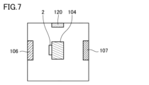
- FIG. 7 is a schematic top view of the cathode arc ion plating apparatus shown in FIG. 6.
- Patent Document 1 and Patent Document 2 Conventionally, as a coating tool material, a nitride or carbonitride film containing Ti and Al as main components has been coated on the surface of a base material (Patent Document 1 and Patent Document 2).
- a nitride or carbonitride film containing Ti and Al as main components has been coated on the surface of a base material (Patent Document 1 and Patent Document 2).
- cutting speeds are becoming faster due to dry machining that does not use cutting fluids and improving machining efficiency, and work materials are becoming more diverse.
- the cutting of heat-resistant alloys, titanium alloys, etc., which are difficult-to-cut materials is increasing, and for this reason, the temperature of the cutting tool tip during the cutting process tends to be high. That is, when the cutting edge temperature becomes high, the life of the cutting tool becomes extremely short. Therefore, there is a need for cutting tools that can exhibit excellent tool life even under such severe cutting conditions.
- a cutting tool includes a base material and a coating disposed on the base material,
- the coating includes a first layer;
- the first layer is composed of alternating layers in which first unit layers and second unit layers are alternately laminated,
- the first unit layer is made of Ti 1-ab Al a Ce b N,
- the a is 0.350 or more and 0.650 or less
- the b is 0.001 or more and 0.100 or less
- the second unit layer is made of Al c Cr 1-c N,
- the c is 0.40 or more and 0.75 or less, The above a and the above c satisfy the relationship c>a.
- the thickness ⁇ 2 of the second unit layer is relative to the thickness ⁇ 1 of the first unit layer.
- the ratio ⁇ 2/ ⁇ 1 is preferably 1 or more and 5 or less. This makes it possible to provide a cutting tool that has a longer tool life, especially in cutting operations performed under conditions where the cutting edge temperature is high.
- the average thickness of the first unit layer is 0.002 ⁇ m or more and 0.2 ⁇ m or less
- the average thickness of the second unit layer is preferably 0.002 ⁇ m or more and 0.2 ⁇ m or less. This makes it possible to provide a cutting tool that has a longer tool life, especially in cutting operations performed under conditions where the cutting edge temperature is high.
- the coating further includes a second layer disposed between the base material and the first layer,
- the composition of the second layer is preferably the same as the composition of the first unit layer or the composition of the second unit layer. This makes it possible to provide a cutting tool that has a longer tool life, especially in cutting operations performed under conditions where the cutting edge temperature is high.
- the composition of the second layer is the same as the composition of the first unit layer,
- the thickness of the second layer is preferably thicker than the thickness of the first unit layer. This makes it possible to provide a cutting tool that has a longer tool life, especially in cutting operations performed under conditions where the cutting edge temperature is high.
- the composition of the second layer is the same as the composition of the second unit layer,
- the thickness of the second layer is preferably thicker than the thickness of the second unit layer. This makes it possible to provide a cutting tool that has a longer tool life, especially in cutting operations performed under conditions where the cutting edge temperature is high.
- the coating further includes a third layer provided on the opposite side of the first layer to the base material,
- the third layer is made of TiAlCeCN. This makes it possible to provide a cutting tool that has a longer tool life, especially in cutting operations performed under conditions where the cutting edge temperature is high.
- a cutting tool includes a substrate and a coating disposed on the substrate,
- the coating comprises a first A layer,
- the first A layer is composed of alternating layers in which first unit layers and third unit layers are alternately laminated,
- the first unit layer is made of Ti 1-a-b Al a Ce b N,
- the a is 0.350 or more and 0.650 or less,
- the b is 0.001 or more and 0.100 or less
- the third unit layer is made of Al d Cr 1-de Me N, M is silicon or boron;
- the d is 0.40 or more and 0.75 or less,
- the e is greater than 0 and not greater than 0.05,
- the a and d satisfy the relationship d>a.
- This disclosure makes it possible to provide cutting tools that have a long tool life, especially in cutting processes that are performed under conditions of high cutting edge temperatures.
- the thickness ⁇ 3 of the third unit layer is relative to the thickness ⁇ 1 of the first unit layer.
- the ratio ⁇ 3/ ⁇ 1 is preferably 1 or more and 5 or less. This makes it possible to provide a cutting tool that has a longer tool life, especially in cutting operations performed under conditions where the cutting edge temperature is high.
- the M is preferably silicon. This makes it possible to provide a cutting tool that has a longer tool life, especially in cutting operations performed under conditions where the cutting edge temperature is high.
- the M is preferably boron. This makes it possible to provide a cutting tool that has a longer tool life, especially in cutting operations performed under conditions where the cutting edge temperature is high.
- the average thickness of the first unit layer is 0.002 ⁇ m or more and 0.2 ⁇ m or less
- the average thickness of the third unit layer is preferably 0.002 ⁇ m or more and 0.2 ⁇ m or less. This makes it possible to provide a cutting tool that has a longer tool life, especially in cutting operations performed under conditions where the cutting edge temperature is high.
- the coating further includes a second layer disposed between the base material and the first A layer,
- the composition of the second layer is preferably the same as the composition of the first unit layer or the composition of the third unit layer. This makes it possible to provide a cutting tool that has a longer tool life, especially in cutting operations performed under conditions where the cutting edge temperature is high.
- the composition of the second layer is the same as the composition of the first unit layer,
- the thickness of the second layer is preferably thicker than the thickness of the first unit layer. This makes it possible to provide a cutting tool that has a longer tool life, especially in cutting operations performed under conditions where the cutting edge temperature is high.
- the composition of the second layer is the same as the composition of the third unit layer,
- the thickness of the second layer is preferably greater than the thickness of the third unit layer. This makes it possible to provide a cutting tool that has a longer tool life, especially in cutting operations performed under conditions where the cutting edge temperature is high.
- the coating further includes a third layer provided on the side opposite to the base material of the first A layer, Preferably, the third layer is made of TiAlCeCN. This makes it possible to provide a cutting tool that has a longer tool life, especially in cutting operations performed under conditions where the cutting edge temperature is high.
- the notation in the format "A to B” means the upper and lower limits of the range (i.e., from A to B), and when there is no unit described in A and only in B, The units of and the units of B are the same.
- the atomic ratio when a compound or the like is expressed by a chemical formula, unless the atomic ratio is specifically limited, it includes all conventionally known atomic ratios, and should not necessarily be limited to only those in the stoichiometric range.
- TiAlCeN when "TiAlCeN" is written, the ratio of the number of atoms constituting TiAlCeN includes all conventionally known atomic ratios.
- FIGS. 1 to 5 A cutting tool according to an embodiment of the present disclosure will be described using FIGS. 1 to 5.
- An embodiment of the present disclosure (hereinafter also referred to as "Embodiment 1") includes: A cutting tool 1 comprising a base material 2 and a coating 3 disposed on the base material 2, The coating 3 includes a first layer 13, 13', The first layers 13, 13' are composed of alternating layers in which first unit layers 12 and second unit layers 15 are alternately laminated, The first unit layer 12 is made of Ti 1-ab Al a Ce b N, The a is 0.350 or more and 0.650 or less, The b is 0.001 or more and 0.100 or less, The second unit layer 15 is made of Al c Cr 1-c N, The c is 0.40 or more and 0.75 or less, The a and the c satisfy the relationship c>a.
- the coating 3 includes first layers 13, 13', and the first layers 13, 13' are formed by alternately laminating the first unit layer 12 and the second unit layer 15. It consists of alternating layers. This reduces the number of grain boundaries in the first layer, thereby improving the "crack resistance” and “oxidation resistance” of the first layers 13, 13'. "Propagation of cracks" at the interface between the unit layer 12 and the second unit layer 15 can be suppressed.
- the coating 3 includes the first layers 13, 13', and the first layers 13, 13' are composed of alternating layers in which the first unit layers 12 and the second unit layers 15 are alternately laminated. Consists of layers.
- the first unit layer 12 is made of Ti 1-ab Al a Ce b N
- the second unit layer 15 is made of Al c Cr 1-c N.
- Ti 1-ab Al a Ce b N is less susceptible to spinodal decomposition at high temperatures than Al c Cr 1-c N. Therefore, in the first unit layer 12, reduction in hardness is suppressed, compressive residual stress increases, and chipping resistance tends to be excellent.
- Al c Cr 1-c N has smaller compressive residual stress than Ti 1-ab Al a Ce b N and has excellent "thermal insulation” (in other words, "heat resistance”).
- the first layer 13, 13' is formed by laminating the first unit layer 12 and the second unit layer 15 alternately, so that the first unit layer 12 has high "hardness” and the second unit layer.
- the small compressive residual stress of the second unit layer 15 is complemented by the large compressive residual stress of the first unit layer 12. Therefore, the hardness, heat resistance, and compressive residual stress of the first layer 13, 13' as a whole can be improved in a well-balanced manner.
- the first unit layer 12 is made of Ti 1-ab Al a Ce b N, a is 0.350 or more and 0.650 or less, and b is It is 0.001 or more and 0.100 or less.
- Al is easily oxidized, a dense oxide layer made of Al 2 O 3 is easily formed on the surface side of the first unit layer 12 .
- Ce has a smaller standard energy of oxide formation than Al, it is more easily oxidized than Al, and a dense oxide layer made of CeO 2 is formed on the outermost surface of the first unit layer 12. easy. These oxide layers improve the "oxidation resistance" of the coating 3, suppress reactivity with the work material, and reduce the coefficient of friction with the work material.
- the lattice constant of CeN is 5.01 ⁇ , which is larger than the lattice constant of TiN, 4.23 ⁇ , and the lattice constant of AlN, 4.12 ⁇ , strain is introduced into the first unit layer 12. 12 tissues become finer. As a result, the first unit layer 12 has a high hardness, so that the "abrasion resistance" of the first unit layer 12 can be improved.
- the first unit layer 12 is made of Ti 1-ab Al a Ce b N
- the second unit layer 15 is made of Al c Cr 1-c N. ...
- the a and the c satisfy the relationship c>a. This is because the difference between the lattice constants of AlN and CrN in the second unit layer 15 is smaller than the difference between the lattice constants of TiN and AlN in the first unit layer 12. , the second unit layer 15 tends to have a higher Al content than the first unit layer 12. Therefore, by increasing the Al content in the second unit layer 15, the Al content contained in the entire first layer 13, 13' can be increased. As a result, the "heat resistance" and "oxidation resistance” of the first layers 13, 13' can be improved.
- the cutting tool 1 has excellent "crack resistance”, excellent “oxidation resistance”, excellent “crack growth suppressing effect”, high “hardness”, and excellent “wear resistance”. , and excellent “heat resistance”, it is possible to provide a cutting tool 1 that has a long tool life, especially in cutting operations performed under conditions where the temperature of the cutting edge is high.
- a cutting tool 1 includes a base material 2 and a coating 3 disposed on the base material 2. It is preferable that the coating 3 covers the entire surface of the base material 2, but even if a part of the substrate 2 is not covered with the coating 3 or the structure of the coating 3 is partially different, the present invention will not apply. It does not depart from the scope of the embodiments.
- the coating 3 is preferably disposed so as to cover at least the surface of the portion of the base material 2 that is involved in cutting.
- the part involved in cutting of the base material 2 refers to the ridgeline of the cutting edge of the base material 2, and the part from the ridgeline of the cutting edge to the base material 2 side, although it depends on the size and shape of the substrate 2. It means a region surrounded by an imaginary plane in which the distance along the perpendicular line to the tangent to the cutting edge ridgeline is, for example, 5 mm, 3 mm, 2 mm, 1 mm, or 0.5 mm.
- the cutting tool 1 of this embodiment can be suitably used as a cutting tool 1 such as a drill, an end mill, an indexable cutting tip for a drill, an indexable cutting tip for an end mill, an indexable cutting tip for milling, an indexable cutting tip for turning, a metal saw, a gear cutting tool, a reamer, and a tap.
- a cutting tool 1 such as a drill, an end mill, an indexable cutting tip for a drill, an indexable cutting tip for an end mill, an indexable cutting tip for milling, an indexable cutting tip for turning, a metal saw, a gear cutting tool, a reamer, and a tap.
- any conventionally known base material 2 of this type can be used.
- cemented carbide WC-based cemented carbide, cemented carbide containing WC and Co, cemented carbide containing carbonitrides such as Ti, Ta, Nb, etc.
- cermet TiC, TiN, TiCN, etc.
- the main component shall be high-speed steel, ceramics (titanium carbide, silicon carbide, silicon nitride, aluminum nitride, aluminum oxide, etc.), cubic boron nitride sintered body, or diamond sintered body. is preferred.
- WC-based cemented carbide and cermet particularly TiCN-based cermet.
- These base materials 2 have an excellent balance between hardness and strength, especially at high temperatures, so when used as the base material 2 of the cutting tool 1, they can contribute to extending the life of the cutting tool 1.
- the coating 3 of Embodiment 1 includes first layers 13, 13'. By covering the base material 2, the coating 3 has the effect of improving various properties of the cutting tool 1, such as wear resistance and chipping resistance, and extending the life of the cutting tool 1. Note that, in addition to the first layers 13 and 13', the coating 3 can include "other layers" described later.
- the coating 3 preferably has a total thickness of 0.5 ⁇ m or more and 15 ⁇ m or less. If the total thickness is less than 0.5 ⁇ m, the coating 3 is too thin, and the life of the cutting tool 1 tends to be shortened. On the other hand, if the total thickness is more than 15 ⁇ m, the coating 3 is prone to chipping in the early stages of cutting, and the life of the cutting tool 1 tends to be shortened.
- the total thickness of the coating 3 can be measured by observing the cross section of the coating 3 using a SEM (scanning electron microscope).
- the observation magnification of the cross-sectional sample is set to 5000 to 10000 times, the observation area is set to 100 to 500 ⁇ m 2 , the thickness width is measured at three points in one field of view, and the average value is taken as the "thickness". The same applies to the thickness of each layer described below unless otherwise specified.
- the compressive residual stress of the coating 3 preferably has an absolute value of 6 GPa or less.
- the compressive residual stress of the coating 3 is a type of internal stress (intrinsic strain) that exists throughout the coating 3, and is a stress expressed as a "-" (negative) numerical value (unit: "GPa” is used in this embodiment).
- GPa negative numerical value
- the concept of a large compressive residual stress refers to a large absolute numerical value
- the concept of a small compressive residual stress refers to a small absolute numerical value.
- an absolute value of the compressive residual stress of 6 GPa or less means that the preferred compressive residual stress for the coating 3 is -6 GPa or more and 0 GPa or less.
- the compressive residual stress of the coating 3 exceeds 0 GPa, it becomes tensile stress, so it tends to be difficult to suppress the propagation of cracks generated from the outermost surface of the coating 3.
- the absolute value of the compressive residual stress exceeds 6 GPa, the stress is too large, and the coating 3 may peel off, especially from the edge portion of the cutting tool 1, before cutting starts, which may shorten the life of the cutting tool 1. .
- the compressive residual stress of the coating 3 is measured by the sin2 ⁇ method (see pages 54 to 66 of "X-ray stress measurement method" (Japan Society of Materials Science, published by Yokendo Co., Ltd., 1981)) using an X-ray residual stress device. be able to.
- the crystal structure of the coating 3 is preferably cubic.
- the crystal structure of the coating 3 is cubic, the hardness of the coating 3 is improved. Therefore, it is preferable that each layer in the coating 3 has a cubic crystal structure. Note that the crystal structure of the coating 3 and each layer in the coating 3 can be analyzed using an X-ray diffraction apparatus known in the art.
- the hardness of the coating 3 is preferably 30 GPa or more and 55 GPa or less, and more preferably 35 GPa or more and 50 GPa or less. This means that the coating 3 has sufficient hardness.
- the hardness of the entire coating 3 can be measured by a nanoindenter method (Nano Indenter XP manufactured by MTS). Specifically, this is performed using a method conforming to ISO14577, with a measurement load of 10 mN (1 gf), and the hardness is measured at three points on the surface of the coating 3, and the average value is taken as the "hardness".
- the first layers 13, 13' of this embodiment are composed of alternating layers in which first unit layers 12 and second unit layers 15 are alternately laminated. As a result, it is possible to improve the "crack resistance” and “oxidation resistance” of the first layers 13, 13', and the “propagation of cracks” at the interface between the first unit layer 12 and the second unit layer 15 is improved. ”, the “crack resistance” and “oxidation resistance” of the coating 3 can be improved, and the “propagation of cracks” in the coating 3 can be suppressed.
- the first layers 13, 13' are composed of alternating layers in which the first unit layer 12 and the second unit layer 15 are alternately laminated
- the cross section of the coating 3 is examined using a TEM (transmission electron microscope). This can be confirmed by observing the difference in contrast.
- the thickness of the first layer 13, 13' is preferably 0.5 ⁇ m or more and 15 ⁇ m or less. If the thickness of the first layer 13, 13' is less than 0.5 ⁇ m, it tends not to exhibit sufficient wear resistance during continuous processing, and if it exceeds 15 ⁇ m, it tends not to have stable chipping resistance during intermittent cutting.
- the thickness of the first layer 13, 13' can be determined by observing and measuring the cross section of the coating 3 using a TEM (transmission electron microscope). Specifically, the thin sample is irradiated with an electron beam, the electrons that have passed through the sample and the scattered electrons are imaged, observed at high magnification, and the thickness of the first layers 13, 13' can be measured. can.
- TEM transmission electron microscope
- the first unit layer 12 is made of Ti 1-ab Al a Ce b N, where a is 0.350 or more and 0.650 or less, and b is 0.001 or more and 0.100 or less. . Thereby, the "oxidation resistance" and "wear resistance” of the coating 3 can be improved.
- the a is preferably 0.400 or more, more preferably 0.450 or more, and even more preferably 0.500 or more.
- the a is preferably 0.650 or less, more preferably 0.600 or less, and even more preferably 0.550 or less.
- the a is preferably 0.400 or more and 0.650 or less, more preferably 0.450 or more and 0.600 or less, and even more preferably 0.500 or more and 0.055 or less.
- the b is preferably 0.005 or more, more preferably 0.01 or more, and even more preferably 0.015 or more.
- the b is preferably 0.070 or less, more preferably 0.050 or less, and even more preferably 0.020 or less.
- the b is preferably 0.005 or more and 0.050 or less, more preferably 0.007 or more and 0.030 or less, and even more preferably 0.010 or more and 0.020 or less.
- Consisting of Ti 1-ab Al a Ce b N means that it can contain inevitable impurities in addition to Ti 1-ab Al a Ce b N as long as the effects of the present disclosure are exhibited. means.
- the unavoidable impurities include oxygen and carbon.
- the total content of unavoidable impurities in the first unit layer 12 is preferably greater than 0 atomic % and less than 1 atomic %.
- atomic % means the ratio (%) of the number of atoms to the total number of atoms constituting the layer. The ratio (%) of the number of atoms to the total number of atoms constituting the layer is determined by the same method as "method for measuring a and b" described later. It has been confirmed that as long as the same cutting tool 1 is used for measurement, there is no variation in the measurement results even if the measurement location is arbitrarily selected.
- the above a and b are determined by elemental analysis by transmission electron microscopy (TEM) observation of a cross section of the sample. Specifically, using the EDS (Energy Dispersive It can be determined by performing elemental analysis. It has been confirmed that as long as the same cutting tool 1 is used for measurement, there is no variation in the measurement results even if the measurement location is arbitrarily selected.
- EDS Electronicgy Dispersive It can be determined by performing elemental analysis. It has been confirmed that as long as the same cutting tool 1 is used for measurement, there is no variation in the measurement results even if the measurement location is arbitrarily selected.
- the second unit layer 15 is made of Al c Cr 1-c N.
- the coating 3 has excellent "heat resistance” and excellent balance due to the fact that AlCrN has an excellent balance of heat barrier properties (in other words, "heat resistance”), "oxidation resistance”, and “toughness”. It can have both "oxidation resistance” and excellent “toughness”.
- heat barrier properties in other words, "heat resistance”
- oxidation resistance oxidation resistance
- toughness heat barrier properties
- It can have both "oxidation resistance” and excellent “toughness”.
- Consisting of Al c Cr 1-c N means that inevitable impurities can be included in addition to Al c Cr 1-c N as long as the effects of the present disclosure are exhibited. Examples of the unavoidable impurities include oxygen and carbon.
- the total content of unavoidable impurities in the second unit layer 15 is preferably greater than 0 atomic % and less than 1 atomic %.
- atomic % means the ratio (%) of the number of atoms to the total number of atoms constituting the layer.
- the ratio (%) of the number of atoms to the total number of atoms constituting the layer is determined by the same method as the above-mentioned "method for measuring a and b". It has been confirmed that as long as the same cutting tool 1 is used for measurement, there is no variation in the measurement results even if the measurement location is arbitrarily selected.
- the c is 0.40 or more and 0.75 or less.
- the second unit layer 15 has a cubic crystal structure, which increases the hardness of the second unit layer 15, and as a result, the "wear resistance" of the second unit layer 15 improves.
- the c is preferably 0.50 or more, more preferably 0.55 or more, and even more preferably 0.60 or more.
- the c is preferably 0.75 or less, more preferably 0.70 or less, and even more preferably 0.65 or less.
- the c is preferably 0.50 or more and 0.75 or less, more preferably 0.55 or more and 0.70 or less, and even more preferably 0.60 or more and 0.65 or less.
- the above c is obtained by the same method as the measurement methods for the above a and b. It has been confirmed that there is no variation in the measurement results even if the measurement points are arbitrarily selected, so long as the measurement is performed using the same cutting tool 1.
- the average thickness of the first unit layer 12 is preferably 0.002 ⁇ m or more and 0.2 ⁇ m or less, and the average thickness of the second unit layer 15 is preferably 0.002 ⁇ m or more and 0.2 ⁇ m or less. According to this, the growth of cracks generated on the surface of the coating 3 can be further suppressed.
- the lower limit of the average thickness of the first unit layer 12 is preferably 0.002 ⁇ m or more, more preferably 0.005 ⁇ m or more, and even more preferably 0.01 ⁇ m or more.
- the upper limit of the average thickness of the first unit layer 12 is preferably 0.2 ⁇ m or less, more preferably 0.15 ⁇ m or less, and even more preferably 0.1 ⁇ m or less.
- the average thickness of the first unit layer 12 is more preferably 0.005 ⁇ m or more and 0.15 ⁇ m or less, and even more preferably 0.01 ⁇ m or more and 0.1 ⁇ m or less.
- the lower limit of the average thickness of the second unit layer 15 is preferably 0.002 ⁇ m or more, more preferably 0.005 ⁇ m or more, and even more preferably 0.01 ⁇ m or more.
- the upper limit of the average thickness of the second unit layer 15 is preferably 0.2 ⁇ m or less, more preferably 0.15 ⁇ m or less, and even more preferably 0.1 ⁇ m or less.
- the average thickness of the second unit layer 15 is more preferably 0.005 ⁇ m or more and 0.15 ⁇ m or less, and even more preferably 0.01 ⁇ m or more and 0.1 ⁇ m or less.
- the average thickness of the first unit layer 12 and the average thickness of the second unit layer 15 can be determined by the same method as the method for measuring the thickness of the first layers 13, 13'.
- the ratio ⁇ 2/ ⁇ 1 of the thickness ⁇ 2 of the second unit layer 15 to the thickness ⁇ 1 of the first unit layer 12 is ⁇ 2/ ⁇ 1.
- , is preferably 1 or more and 5 or less (FIG. 5). Since the "thermal conductivity" of the second unit layer 15 is low, the second unit layer 15 has a property that it is difficult to transfer heat generated during cutting to the base material 2.
- ⁇ 2/ ⁇ 1 is preferably 1 or more, more preferably 1.5 or more, and even more preferably 2 or more.
- ⁇ 2/ ⁇ 1 is preferably 5 or less, more preferably 4 or less, and even more preferably 3 or less.
- ⁇ 2/ ⁇ 1 is preferably 1 or more and 5 or less, more preferably 1.5 or more and 4 or less, and even more preferably 2 or more and 3 or less.
- the number of stacked layers of each of the first unit layer 12 and the second unit layer 15 is preferably 10 or more and 500 or less. According to this, there is a tendency to easily obtain "the effect of improving hardness and compressive residual stress in a well-balanced manner by laminating the first unit layer 12 and the second unit layer 15."
- the number of stacked layers of each of the first unit layer 12 and the second unit layer 15 is more preferably 100 or more and 400 or less, and even more preferably 200 or more and 350 or less.
- the number of stacked layers of the first unit layer 12 and the second unit layer 15 is determined by observing and measuring the cross section of the coating 3 using a TEM (transmission electron microscope). You can ask for it. Specifically, a thin sample is irradiated with an electron beam, the electrons that have passed through the sample and the scattered electrons are imaged, and observed at high magnification. The number of laminated layers can be measured.
- TEM transmission electron microscope
- the coating 3 further includes a second layer 16 disposed between the base material 2 and the first layers 13, 13', and the composition of the second layer 16 is different from that of the first unit layer 12 or the second layer 16.
- the composition is preferably the same as that of the unit layer 15 (FIGS. 3 and 4). Thereby, the adhesion between the base material 2 and the coating 3 can be improved.
- composition of the second layer 16 is the same as that of the first unit layer 12, even if the base material 2 is exposed at the initial stage of cutting, oxidation from the interface between the base material 2 and the coating 3 is prevented. Can be suppressed.
- the thickness of the second layer 16 is preferably thicker than that of the first unit layer 12. This can further increase the adhesion between the substrate 2 and the coating 3. Even if the substrate 2 is exposed at the beginning of cutting, oxidation from the interface between the substrate 2 and the coating 3 can be further suppressed.
- the thickness of the second layer 16 is thicker than that of the first unit layer 12
- the thickness of the second layer 16 is preferably 2.0 times or more the thickness of the first unit layer 12, more preferably 4.0 times or more, and even more preferably 10.0 times or more.
- the thickness of the second layer 16 is preferably 500 times or less the thickness of the first unit layer 12, more preferably 120 times or less, and even more preferably 50 times or less.
- the thickness of the second layer 16 is preferably 2.0 times or more and 500 times or less than the thickness of the first unit layer 12, more preferably 4.0 times or more and 120 times or less, and even more preferably 10.0 times or more and 50 times or less.
- the thickness of the second layer 16 is preferably 0.1 ⁇ m or more.
- the thickness of the second layer 16 is less than 0.1 ⁇ m, it tends to be difficult to obtain the effect of suppressing oxidation from the interface between the substrate 2 and the coating 3, which is achieved by making the second layer 16 the same composition as the first unit layer 12.
- the composition of the second layer 16 is the same as that of the first unit layer 12, it is more preferable that the thickness of the second layer 16 is 0.3 ⁇ m or more, and even more preferable that it is 0.4 ⁇ m or more.
- the thickness of the second layer 16 is preferably 2 ⁇ m or less.
- the composition of the second layer 16 is the same as that of the first unit layer 12, the first layer of the first layer 13, 13' is placed immediately above the second layer 16 having the same composition as the first unit layer 12.
- the unit layers 12 may be stacked (FIG. 4), or the second unit layers 15 may be stacked (FIG. 3).
- the composition of the second layer 16 is the same as that of the first unit layer 12, and the first unit layer 12 of the first layers 13, 13' is laminated directly above the second layer 16.
- the second layer 16 and the first unit layer 12 of the first layers 13, 13' have a continuous crystal structure.
- the stress in the second unit layer 15 tends to be small.
- the peeling resistance of the coating 3 can be improved in intermittent machining such as end milling or end milling.
- the thickness of the second layer 16 is preferably thicker than the thickness of the second unit layer 15. This makes it possible to further improve the peeling resistance of the coating 3, particularly in interrupted machining such as milling or end milling where a load is repeatedly applied to the cutting edge.
- the thickness of the second layer 16 is thicker than the thickness of the second unit layer 15
- the thickness of the second layer 16 is more than 1.0 times the thickness of the second unit layer 15. It can be rephrased as ⁇ .
- the thickness of the second layer 16 is preferably 2.0 times or more, more preferably 4.0 times or more, and 10.0 times or more the thickness of the second unit layer 15. More preferred.
- the thickness of the second layer 16 is preferably 500 times or less, more preferably 120 times or less, and even more preferably 50 times or less than the thickness of the second unit layer 15.
- the thickness of the second layer 16 is preferably 2.0 times or more and 500 times or less, more preferably 4.0 times or more and 120 times or less, and 10.0 times or less, the thickness of the second unit layer 15. It is more preferable that it is 50 times or more.
- the thickness of the second layer 16 is preferably 0.1 ⁇ m or more.
- the thickness of the second layer 16 is less than 0.1 ⁇ m, it tends to be difficult to obtain the effect of improving peel resistance by making the second layer 16 have the same composition as the second unit layer 15.
- the thickness of the second layer 16 is 0.3 ⁇ m or more, and even more preferable that it is 0.4 ⁇ m or more.
- the thickness of the second layer 16 is preferably 2 ⁇ m or less.
- the composition of the second layer 16 is the same as that of the second unit layer 15, the first layer of the first layer 13, 13'
- the unit layers 12 may be stacked (FIG. 4), or the second unit layers 15 may be stacked (FIG. 3).
- the composition of the second layer 16 is the same as that of the second unit layer 15, and the second unit layer 15 of the first layers 13, 13' is laminated directly above the second layer 16.
- the second layer 16 and the second unit layer 15 of the first layers 13, 13' have a continuous crystal structure.
- the coating 3 further includes a third layer 14 provided on the side opposite the base material 2 of the first layers 13, 13', and the third layer 14 is preferably made of TiAlCeCN (FIGS. 1 to 4). Thereby, the coefficient of friction of the coating 3 can be lowered, and the life of the cutting tool 1 can be extended.
- carbonitrides tend to have a lower coefficient of friction with the work material than nitrides. This reduction in the coefficient of friction is believed to be due to the contribution of carbon atoms.
- the coating 3 includes the third layer 14, the coefficient of friction of the coating 3 with the work material decreases, and the cutting tool 1 has a longer life.
- the third layer 14 it is possible to impart a predetermined color by adjusting the composition ratio of N and C. Thereby, design and distinctiveness can be imparted to the appearance of the cutting tool 1, making it commercially useful.
- the thickness of the third layer 14 is preferably 0.1 ⁇ m or more. If the thickness of the third layer 14 is less than 0.1 ⁇ m, the effect of imparting lubricity by the third layer 14 may be difficult to obtain. On the other hand, the upper limit of the thickness of the third layer 14 is not particularly limited, but if it exceeds 2 ⁇ m, the above-mentioned lubricity imparting effect tends to be unable to be further improved. Therefore, in consideration of cost, the thickness of the third layer 14 is preferably 2 ⁇ m or less.
- the intermediate layer is a layer disposed between the second layer 16 and the first layer 13, 13' or between the first layer 13, 13' and the third layer 14.
- Examples of the intermediate layer include TiAlCeN, AlCrN, AlCrBN, AlCrSiN, and the like.
- the thickness of the intermediate layer can be 0.1 ⁇ m or more and 2 ⁇ m or less, 0.3 ⁇ m or more and 1.5 ⁇ m or less, and 0.4 ⁇ m or more and 1.0 ⁇ m or less.
- FIGS. 1 to 5 A cutting tool according to another embodiment of the present disclosure will be described using FIGS. 1 to 5.
- Another embodiment of the present disclosure (hereinafter also referred to as “Embodiment 2”) includes: A cutting tool comprising a base material and a coating disposed on the base material, The coating includes a first A layer, The first A layer consists of alternating layers in which first unit layers and third unit layers are alternately laminated, The first unit layer is made of Ti 1-ab Al a Ce b N, The a is 0.350 or more and 0.650 or less, The b is 0.001 or more and 0.100 or less, The third unit layer is made of Al d Cr 1-de M e N, The M is silicon or boron, The d is 0.40 or more and 0.75 or less, The e is greater than 0 and less than or equal to 0.05, The a and the d satisfy the relationship d>a.
- the cutting tool 1 of Embodiment 2 is characterized in that ⁇ the coating 3 includes the ⁇ first A layers 13 and 13'''' and that ⁇ the composition of the second layer 16 is the same as the composition of the first unit layer 12 or the ⁇ third unit layer''.
- the coating 3 further includes a third layer 14 provided on the side opposite to the base material 2 of the first A layer 13, 13', and
- the third layer 14 has the same configuration as the first embodiment except that the third layer 14 is preferably made of TiAlCeCN. Below, the "first A layer 13, 13'" and the "second layer” will be explained.
- the first A layers 13, 13' in this embodiment are made of alternating layers in which the first unit layers 12 and the third unit layers 17 are alternately laminated. This improves the "crack resistance” and “oxidation resistance” of the first A layers 13, 13' and suppresses the "progression of cracks" at the interface between the first unit layers 12 and the third unit layers 17, thereby improving the "crack resistance” and “oxidation resistance” of the coating 3 and suppressing the "progression of cracks" of the coating 3.
- the fact that "the first A layers 13, 13' are made of alternating layers in which the first unit layers 12 and the third unit layers 17 are alternately laminated" can be confirmed by observing the cross section of the coating 3 with a TEM (transmission electron microscope) and observing the difference in contrast.
- the thickness of the first A layer 13, 13' is preferably 0.5 ⁇ m or more and 15 ⁇ m or less. If the thickness of the first A layer 13, 13' is less than 0.5 ⁇ m, it tends not to exhibit sufficient wear resistance in continuous processing, and if it exceeds 15 ⁇ m, it tends not to have stable chipping resistance in intermittent cutting.
- the thickness of the first A layer 13, 13' can be determined by observing and measuring the cross section of the coating 3 using a TEM (transmission electron microscope). Specifically, the thin sample is irradiated with an electron beam, the electrons that have passed through the sample and the scattered electrons are imaged, observed at high magnification, and the thickness of the first A layer 13, 13' can be measured. can.
- TEM transmission electron microscope
- the first unit layer 12 is made of Ti 1-ab Al a Ce b N, where a is 0.350 or more and 0.650 or less, and b is 0.001 or more and 0.100 or less. . Thereby, the "oxidation resistance" and "wear resistance” of the coating 3 can be improved.
- the a is preferably 0.400 or more, more preferably 0.450 or more, and even more preferably 0.500 or more.
- the a is preferably 0.640 or less, more preferably 0.600 or less, and even more preferably 0.550 or less.
- the a is preferably 0.400 or more and 0.650 or less, more preferably 0.450 or more and 0.600 or less, and even more preferably 0.500 or more and 0.550 or less.
- the b is preferably 0.005 or more, more preferably 0.007 or more, and even more preferably 0.010 or more.
- the b is preferably 0.070 or less, more preferably 0.050 or less, and even more preferably 0.020 or less.
- the b is preferably 0.005 or more and 0.050 or less, more preferably 0.007 or more and 0.030 or less, and even more preferably 0.010 or more and 0.020 or less.
- Consisting of Ti 1-ab Al a Ce b N means that it can contain inevitable impurities in addition to Ti 1-ab Al a Ce b N as long as the effects of the present disclosure are exhibited. means.
- the unavoidable impurities include oxygen and carbon.
- the total content of unavoidable impurities in the first unit layer 12 is preferably greater than 0 atomic % and less than 1 atomic %.
- atomic % means the ratio (%) of the number of atoms to the total number of atoms constituting the layer. The ratio (%) of the number of atoms to the total number of atoms constituting the layer is determined by the same method as "method for measuring a and b" described later. It has been confirmed that as long as the same cutting tool 1 is used for measurement, there is no variation in the measurement results even if the measurement location is arbitrarily selected.
- the above a and b are determined by elemental analysis by transmission electron microscopy (TEM) observation of a cross section of the sample. Specifically, we used EDS (Energy Dispersive X-ray Spectroscopy) attached to the TEM to calculate the energy and number of occurrences of characteristic It is determined by measurement and elemental analysis. It has been confirmed that as long as the same cutting tool 1 is used for measurement, there is no variation in the measurement results even if the measurement location is arbitrarily selected.
- EDS Electronic Dispersive X-ray Spectroscopy
- the third unit layer 17 is made of Al d Cr 1-de M e N, where M is silicon or boron. Thereby, the third unit layer 17 can have both excellent hardness and excellent oxidation resistance. Although the mechanism is not clear in detail, the following mechanism is inferred.
- boron increases the hardness of the third unit layer 17 and increases the hardness of the entire coating 3. Further, the boron oxide formed by oxidation of the surface of the cutting tool 1 during cutting densifies the Al oxide in the third unit layer 17, and as a result, the oxidation resistance of the third unit layer 17 decreases. improves. Furthermore, since boron oxide has a low melting point, it acts as a lubricant during cutting, and can suppress adhesion of the work material.
- the hardness and oxidation resistance of the third unit layer 17 are improved by making the structure of the third unit layer 17 finer, and as a result, the hardness and oxidation resistance of the entire coating 3 are improved. oxidation properties are improved.
- the ratio (%) of the number of atoms to the total number of atoms constituting the layer is determined by the same method as the above-mentioned "method for measuring a and b". It has been confirmed that as long as the same cutting tool 1 is used for measurement, there is no variation in the measurement results even if the measurement location is arbitrarily selected.
- the d is 0.40 or more and 0.75 or less.
- the crystal structure of the third unit layer 15 becomes cubic, and the third unit layer 15 becomes highly hard, and as a result, the "wear resistance" of the third unit layer 15 improves. .
- the d is preferably 0.50 or more, more preferably 0.55 or more, and even more preferably 0.60 or more.
- the c is preferably 0.75 or less, more preferably 0.70 or less, and even more preferably 0.65 or less.
- the c is preferably 0.50 or more and 0.75 or less, more preferably 0.55 or more and 0.70 or less, and even more preferably 0.60 or more and 0.65.
- the e is greater than 0 and less than or equal to 0.05. Thereby, the hardness of the first A layers 13, 13' and the oxidation resistance of the first A layers 13, 13' can be improved.
- the e is preferably 0.002 or more, more preferably 0.005 or more, and even more preferably 0.01 or more.
- the e is preferably 0.04 or less, more preferably 0.03 or less, and even more preferably 0.02 or less.
- the e is preferably 0.002 or more and 0.05 or less, more preferably 0.005 or more and 0.03 or less, and even more preferably 0.01 or more and 0.02 or less.
- the above d and the above e are determined by the same method as the above "method for measuring a and b". It has been confirmed that as long as the same cutting tool 1 is used for measurement, there is no variation in the measurement results even if the measurement location is arbitrarily selected.
- the average thickness of the first unit layer 12 is preferably 0.002 ⁇ m or more and 0.2 ⁇ m or less, and the average thickness of the third unit layer 17 is preferably 0.002 ⁇ m or more and 0.2 ⁇ m or less. According to this, the growth of cracks generated on the surface of the coating 3 can be further suppressed.
- the lower limit of the average thickness of the first unit layer 12 is preferably 0.002 ⁇ m or more, more preferably 0.005 ⁇ m or more, and even more preferably 0.01 ⁇ m or more.
- the upper limit of the average thickness of the first unit layer 12 is preferably 0.2 ⁇ m or less, more preferably 0.15 ⁇ m or less, and even more preferably 0.1 ⁇ m or less.
- the average thickness of the first unit layer 12 is more preferably 0.005 ⁇ m or more and 0.15 ⁇ m or less, and even more preferably 0.01 ⁇ m or more and 0.1 ⁇ m or less.
- the lower limit of the average thickness of the third unit layer 17 is preferably 0.002 ⁇ m or more, more preferably 0.005 ⁇ m or more, and even more preferably 0.01 ⁇ m or more.
- the upper limit of the average thickness of the third unit layer 17 is preferably 0.2 ⁇ m or less, more preferably 0.15 ⁇ m or less, and even more preferably 0.1 ⁇ m or less.
- the average thickness of the third unit layer 17 is more preferably 0.005 ⁇ m or more and 0.15 ⁇ m or less, and even more preferably 0.01 ⁇ m or more and 0.1 ⁇ m or less.
- the average thickness of the first unit layer 12 and the average thickness of the third unit layer 17 can be determined by the same method as the method for measuring the thickness of the first A layer 13, 13'.
- the ratio ⁇ 3/ ⁇ 1 of the thickness ⁇ 3 of the third unit layer 17 to the thickness ⁇ 1 of the first unit layer 12 is ⁇ 3/ ⁇ 1. , is preferably 1 or more and 5 or less (FIG. 5). Since the "thermal conductivity" of the third unit layer 17 is low, the third unit layer 17 has a property that it is difficult to transfer heat generated during cutting to the base material 2.
- ⁇ 3/ ⁇ 1 is preferably 1 or more, more preferably 1.5 or more, and even more preferably 2 or more.
- ⁇ 3/ ⁇ 1 is preferably 5 or less, more preferably 4 or less, and even more preferably 3 or less.
- ⁇ 3/ ⁇ 1 is preferably 1 or more and 5 or less, more preferably 1.5 or more and 4 or less, and even more preferably 2 or more and 3 or less.
- the number of stacked layers of each of the first unit layer 12 and the third unit layer 17 is preferably 10 or more and 500 or less. According to this, there is a tendency to easily obtain "the effect of improving hardness and compressive residual stress in a well-balanced manner by laminating the first unit layer 12 and the third unit layer 17."
- the number of stacked layers of each of the first unit layer 12 and the third unit layer 17 is more preferably 100 or more and 400 or less, and even more preferably 200 or more and 350 or less.
- the number of stacked layers of the first unit layer 12 and the third unit layer 17 is determined by the method for measuring "the number of stacked layers of each of the first unit layer 12 and second unit layer 15" described above. It can be determined by a similar method.
- the coating 3 further includes a second layer 16 disposed between the base material 2 and the first A layer 13, 13', and the composition of the second layer 16 is different from that of the first unit layer 12 or the third unit layer 12.
- the composition is preferably the same as that of the unit layer 17 (FIGS. 3 and 4).
- composition of the second layer 16 is the same as that of the first unit layer 12, even if the base material 2 is exposed at the initial stage of cutting, oxidation from the interface between the base material 2 and the coating 3 is prevented. Can be suppressed.
- the thickness of the second layer 16 is preferably thicker than the thickness of the first unit layer 12.
- the adhesion between the base material 2 and the coating 3 can be further improved.
- the base material 2 is exposed at the initial stage of cutting, oxidation from the interface between the base material 2 and the coating 3 can be further suppressed.
- the thickness of the second layer 16 is thicker than the thickness of the first unit layer 12
- the thickness of the second layer 16 is more than 1.0 times the thickness of the first unit layer 12". It can be rephrased as ⁇ .
- the thickness of the second layer 16 is preferably 2.0 times or more, more preferably 4.0 times or more, and 10.0 times or more the thickness of the first unit layer 12. More preferred.
- the thickness of the second layer 16 is preferably 500 times or less, more preferably 120 times or less, and even more preferably 50 times or less than the first unit layer 12.
- the thickness of the second layer 16 is preferably 2.0 times or more and 500 times or less, more preferably 4.0 times or more and 120 times or less, and 10.0 times or less, the thickness of the first unit layer 12. It is more preferable that it is 50 times or more.
- the thickness of the second layer 16 is preferably 0.1 ⁇ m or more.
- the thickness of the second layer 16 is less than 0.1 ⁇ m, it tends to be difficult to obtain the effect of suppressing oxidation from the interface between the substrate 2 and the coating 3, which is achieved by making the second layer 16 the same composition as the first unit layer 12.
- the composition of the second layer 16 is the same as that of the first unit layer 12, it is more preferable that the thickness of the second layer 16 is 0.3 ⁇ m or more, and even more preferable that the thickness is 0.4 ⁇ m or more.
- the thickness of the second layer 16 is preferably 2 ⁇ m or less.
- the composition of the second layer 16 is the same as that of the first unit layer 12, the first layer of the first A layer 13, 13' The unit layers 12 may be stacked (FIG. 4), or the second unit layers 15 may be stacked (FIG. 3).
- the composition of the second layer 16 is the same as that of the first unit layer 12, and the first unit layer 12 of the first A layer 13, 13' is laminated directly above the second layer 16. In this case, the second layer 16 and the first unit layer 12 of the first A layer 13, 13' have a continuous crystal structure.
- the stress in the third unit layer 17 tends to be small.
- the peeling resistance of the coating 3 can be improved in intermittent machining such as end milling or end milling.
- the thickness of the second layer 16 is preferably thicker than the thickness of the third unit layer 17. This makes it possible to further improve the peeling resistance of the coating 3, particularly in interrupted machining such as milling or end milling where a load is repeatedly applied to the cutting edge.
- the thickness of the second layer 16 is thicker than the thickness of the third unit layer 17
- the thickness of the second layer 16 is more than 1.0 times the thickness of the third unit layer 17. It can be rephrased as ⁇ .
- the thickness of the second layer 16 is preferably 2.0 times or more, more preferably 4.0 times or more, and 10.0 times or more the thickness of the third unit layer 17. More preferred.
- the thickness of the second layer 16 is preferably 500 times or less, more preferably 120 times or less, and even more preferably 50 times or less than the third unit layer 17.
- the thickness of the second layer 16 is preferably 2.0 times or more and 500 times or less, more preferably 4.0 times or more and 120 times or less, and 10.0 times the thickness of the third unit layer 17. It is more preferable that it is 50 times or more.
- the thickness of the second layer 16 is preferably 0.1 ⁇ m or more. If the thickness of the second layer 16 is less than 0.1 ⁇ m, it tends to be difficult to obtain the effect of improving peeling resistance by making the second layer 16 have the same composition as the third unit layer 17.
- the thickness of the second layer 16 is more preferably 0.3 ⁇ m or more, and even more preferably 0.4 ⁇ m or more.
- the upper limit of the thickness of the second layer 16 is not particularly limited, but if it exceeds 2 ⁇ m, the above-mentioned peel resistance tends not to be further improved. Therefore, in consideration of cost, the thickness of the second layer 16 is preferably 2 ⁇ m or less.
- the composition of the second layer 16 is the same as that of the third unit layer 17, the first layer of the first A layer 13, 13'
- the unit layers 12 may be stacked (FIG. 4), or the third unit layer 17 may be stacked (FIG. 3).
- the composition of the second layer 16 is the same as that of the third unit layer 17, and the third unit layer 17 of the first A layers 13, 13' is laminated directly above the second layer 16.
- the second layer 16 and the third unit layer 17 of the first A layer 13, 13' have a continuous crystal structure.
- Embodiment 3 Cutting tool manufacturing method
- the manufacturing method includes a first step of preparing a base material and a second step of forming a film on the base material.
- the second step includes a step of forming a first layer or a first A layer. Details of each step will be explained below.
- a base material is prepared.
- the base material the base material described in Embodiment 1 can be used.
- a commercially available base material may be used, or it may be manufactured using a general powder metallurgy method.
- a general powder metallurgy method for example, a mixed powder is obtained by mixing WC powder, Co powder, etc. using a ball mill or the like. After drying the mixed powder, it is molded into a predetermined shape to obtain a molded body. Further, the compact is sintered to obtain a WC-Co cemented carbide (sintered compact). Next, by subjecting the sintered body to a predetermined cutting edge processing such as honing, a base material made of WC-Co cemented carbide can be manufactured. Any base material other than those mentioned above can be prepared as long as it is conventionally known as this type of base material.
- the second step includes a step of forming a first layer or a first A layer.
- the first layer is formed by alternately stacking the first unit layer and the second unit layer using a physical vapor deposition (PVD) method. Further, in the “step of forming the first A layer”, the first A layer is formed by alternately stacking the first unit layer and the third unit layer using the PVD method.
- PVD physical vapor deposition
- the present inventors investigated various methods for forming the first layer and the first A layer, and found that it is preferable to use a physical vapor deposition method.
- the PVD method at least one selected from the group consisting of cathode arc ion plating method, balanced magnetron sputtering method, unbalanced magnetron sputtering method, and HiPIMS method can be used.
- the cathode arc ion plating method which has a high ionization rate of raw material elements.
- the cathode arc ion plating method it is possible to perform metal ion bombardment treatment on the surface of the base material before forming the first layer. Adhesion with the film is significantly improved.
- a base material is installed in the device and a target is installed as a cathode, and then a high voltage is applied to the target to cause an arc discharge to ionize the atoms that make up the target. This can be done by depositing the substance on the substrate by evaporation.
- a base material is placed in an apparatus, a target is placed on a magnetron electrode equipped with a magnet that forms a balanced magnetic field, and high-frequency power is applied between the magnetron electrode and the base material.
- This can be carried out by generating a gas plasma, colliding the ions of the gas generated by the generation of the gas plasma with the target, and depositing the atoms emitted from the target onto the base material.
- the unbalanced magnetron sputtering method can be performed, for example, by making the magnetic field generated by the magnetron electrode in the balanced magnetron sputtering method described above unbalanced.
- the HiPIMS method which can apply a high voltage and obtain a dense film, can also be used.
- the second step can include a surface treatment step such as surface grinding and shot blasting.
- the second step includes forming other layers (base layer (second layer), intermediate layer, surface layer (third layer), etc.). ).
- the coating includes other layers (base layer (second layer), intermediate layer, surface layer (third layer), etc.)
- these layers can be formed by conventionally known methods.
- These other layers can be formed by conventionally known chemical vapor deposition methods or physical vapor deposition methods. From the viewpoint that other layers can be formed continuously with the first unit layer, the second unit layer, or the third unit layer within one physical vapor deposition apparatus, other layers may be formed by a physical vapor deposition method. is preferred.
- FIG. 6 is a schematic cross-sectional view of the cathodic arc ion plating apparatus used in this example
- FIG. 7 is a schematic top view of the apparatus of FIG.
- a cathode 106 for the first unit layer, a cathode 107 for the second unit layer, and a cathode 120 for the third layer are provided in the chamber 101, which are alloy targets serving as metal raw materials for the coating. and a rotary base material holder 104 for installing the base material 2 are attached.
- An arc power source 108 is attached to the cathode 106, and an arc power source 109 is attached to the cathode 107.
- a bias power supply 110 is attached to the base material holder 104.
- a gas introduction port through which a gas 105 is introduced, and a gas exhaust port 103 is provided to adjust the pressure inside the chamber 101. It has a structure that allows the gas inside 101 to be sucked.
- the pressure inside the chamber 101 is reduced by a vacuum pump, and the temperature is heated to 500°C by a heater installed in the apparatus while rotating the base material 2, so that the pressure inside the chamber 101 is reduced to 1.0 ⁇ 10 -4 Vacuuming was performed until Pa.
- argon gas is introduced from the gas inlet to maintain the pressure inside the chamber 101 at 2.0 Pa, and the voltage of the bias power supply 110 is gradually increased to -1000 V to clean the surface of the base material 2 for 15 minutes. I did it.
- the base material was cleaned by exhausting argon gas from the chamber 101 (argon bombardment treatment).
- base materials for cutting tools according to samples 1-1 to 1-24, 1-27, 1-28, and 1-101 to 1-110 were prepared.
- Step of forming a film on the base material Step of forming a film on the base material
- the temperature of the base material 2 is set to 500°C
- the reaction gas pressure is set to 2.0 Pa
- the voltage of the bias power supply 110 is set to -50V to -50V.
- composition of the cathode 106 is adjusted so that the ratios of Ti, Al, and Ce are the same as the composition ratios of the first unit layer in Tables 1 and 2. Further, the composition of the cathode 107 is adjusted so that the ratio of Cr and Al is the same as the ratio of the composition of the second unit layer in Tables 1 and 2.
- the first layer was formed by alternately stacking the first unit layer and the second unit layer one by one on the second layer, with the number of layers shown in Tables 1 and 2, respectively.
- the first layer was formed by alternately stacking the first unit layer and the second unit layer one by one on the substrate, with the number of layers shown in Tables 1 and 2, respectively.
- the thickness of the second layer, and the thickness and number of layers of the first unit layer and the second unit layer in the first layer were adjusted by the rotation speed of the substrate. Then, the current supplied to the evaporation source was stopped when the thicknesses of the second layer and the first layer reached the thicknesses shown in Tables 1 and 2, respectively.
- the cathode is By supplying an arc current of 100 A to the cathode 120, metal ions were generated from the cathode 120 to form a third layer on the first layer.
- the current supplied to the evaporation source was stopped.
- the composition of the cathode 120 is adjusted so that the ratios of Ti, Al, and Ce are the same as the ratios of the composition of the third layer in Tables 1 and 2.
- the ratio of nitrogen to carbon in the composition of the third layer was adjusted by the ratio of the amount of nitrogen introduced to the amount of methane gas introduced.
- the composition of the first unit layer i.e., a and b
- the composition of the second unit layer i.e., c
- the composition of the second layer the composition of the third layer, the number of laminated layers
- the The average thickness of one unit layer, the average thickness of the second unit layer, the thickness of the first layer, the thickness of the second layer, the thickness of the third layer, and ⁇ 2/ ⁇ 1 were measured.
- composition of the second layer of each sample cutting tool was determined by the method described in embodiment 1. The results obtained are shown in the "composition” column of the “second layer” column in Tables 1 and 2, respectively.
- composition of the third layer of each sample cutting tool was determined by the method described in embodiment 1. The results obtained are shown in the "composition” column of the "third layer” column in Tables 1 and 2, respectively. Note that when “-" is written in the "composition” column of the "second layer” column in Tables 1 and 2, it means that the second layer does not exist, and when “-” is written in the "composition” column of the "third layer” column in Tables 1 and 2, it means that the third layer does not exist.
- the obtained results are shown in the "thickness [ ⁇ m]” column in the “first layer” column of Tables 1 and 2, respectively. Furthermore, the thickness of the second layer was determined for each sample cutting tool by the method described in Embodiment 1. The obtained results are shown in the “Thickness [ ⁇ m]” column in the “Second layer” column of Tables 1 and 2, respectively. Furthermore, the thickness of the third layer was determined for each sample cutting tool by the method described in Embodiment 1. The obtained results are shown in the "Thickness [ ⁇ m]” column in the "Third layer” column of Tables 1 and 2, respectively.
- Cutting tool life evaluation> (Cutting test 1: Continuous turning test) A dry continuous turning test was performed on the CNMG120408-shaped cutting tools of samples 1-1 to 1-24, 1-27, 1-28, and 1-101 to 1-110 under the following cutting conditions, and the flank surface of the cutting edge was The time until the amount of wear reached 0.2 mm was measured. The results are listed in the "Cutting time [minutes]" column of Tables 1 and 2. Note that in Tables 1 and 2, a longer cutting time indicates a longer tool life.
- the cutting tools according to Samples 1-1 to 1-24, 1-27, and 1-28 had a lower amount of flank wear on the cutting edge in the continuous turning test than the cutting tools according to Samples 1-101 to 1-110. It was confirmed that there was a significant reduction in In other words, the cutting tools according to Samples 1-1 to 1-24, 1-27, and 1-28 were cut under conditions where the cutting edge temperature was particularly high compared to the cutting tools according to Samples 1-101 to 1-110. It was confirmed that the tool has a long tool life even in cutting operations.
- the cutting tools according to samples 1-1 to 1-24, 1-27, and 1-28 have a significantly increased cutting length of the cutting edge compared to the cutting tools according to samples 1-101 to 1-110. This was confirmed. In other words, the cutting tools according to Samples 1-1 to 1-24, 1-27, and 1-28 were cut under conditions where the cutting edge temperature was particularly high compared to the cutting tools according to Samples 1-101 to 1-110. It was confirmed that the tool has a long tool life even in cutting operations.
- Example 2 ⁇ Preparation of cutting tools ⁇ ⁇ Production of cutting tools related to samples 2-1 to 2-19 and 2-101 to 2-110>
- a second layer and a first A layer having the compositions shown in Tables 3 and 4 were formed on the base material.
- composition of the cathode 106 is adjusted so that the ratios of Ti, Al, and Ce are the same as the composition ratios of the first unit layer in “Tables 3 and 4.” Further, the composition of the cathode 107 is adjusted so that the ratio of Cr, Al, and “Si, B" is the same as the ratio of the composition of the "third unit layer” in “Tables 3 and 4.” ” point and “If the second layer is formed, the “first A layer” is formed by alternating the first unit layer and the “third unit layer” one layer at a time on the second layer, and the “Table 3 It was formed by laminating the number of laminated layers shown in Table 4.
- the "first A layer” is formed by alternating the first unit layer and the "third unit layer” one by one on the base material as shown in “Table 3 and Table 4". It was formed by laminating the respective number of layers. The current supplied to the evaporation source was stopped when the thicknesses of the second layer and the first A layer reached the thicknesses shown in Tables 3 and 4, respectively. '' and when the thickness of the third layer reached the thickness shown in Tables 3 and 4, the current supplied to the evaporation source was stopped.
- composition of the cathode 120 is adjusted so that the ratio of Ti, Al, and Ce is the same as the ratio of the composition of the third layer in "Tables 3 and 4."
- Samples 2-1 to 2 were prepared in the same manner as the cutting tools for Samples 1-1 to 1-24, 1-27, 1-28, and 1-101 to 1-110, except for -19, cutting tools related to 2-101 to 2-110 were manufactured.
- the composition of the first unit layer i.e., a and b
- the composition of the third unit layer i.e., d and e
- the composition of the second layer the composition of the third layer
- the number of laminated layers the average thickness of the first unit layer, the average thickness of the third unit layer, the thickness of the first A layer, the thickness of the second layer, the thickness of the third layer, and ⁇ 3/ ⁇ 1.
- composition (a and b) of first unit layer Regarding the cutting tool of each sample, the above a was determined by the method described in Embodiment 1. The obtained results are shown in the "a” column of Tables 3 and 4, respectively. Further, the above b was determined for each sample cutting tool by the method described in Embodiment 1. The obtained results are shown in the "b” column of Tables 3 and 4, respectively.
- composition of the second layer was determined by the method described in Embodiment 1.
- composition of the third layer of each sample cutting tool was determined by the method described in Embodiment 1.
- the obtained results are shown in the "Composition” column in the "Third layer” column of Tables 3 and 4, respectively.
- the average thickness of the first unit layer was determined by the method described in embodiment 2. The results obtained are shown in the "Average thickness [ ⁇ m]” column in the "First unit layer” column of Tables 3 and 4, respectively.
- the average thickness of the third unit layer was determined by the method described in embodiment 2. The results obtained are shown in the "Average thickness [ ⁇ m]” column in the “Third unit layer” column of Tables 3 and 4, respectively.
- the thickness of the 1A layer was determined by the method described in embodiment 2.
- the results obtained are shown in the "Thickness [ ⁇ m]” column in the "1A layer” column of Tables 3 and 4, respectively.
- the thickness of the second layer was determined by the method described in embodiment 1.
- the results obtained are shown in the "Thickness [ ⁇ m]” column in the “Second layer” column of Tables 3 and 4, respectively.
- the thickness of the third layer was determined by the method described in embodiment 1.
- the results obtained are shown in the "Thickness [ ⁇ m]” column of the "Third Layer” column in Tables 3 and 4, respectively.
- Cutting test 4 milling test
- the cutting length of the cutting edge of the cutting tools according to Samples 2-1 to 2-19 was significantly increased compared to the cutting tools according to Samples 2-101 to 2-110.
- the cutting tools according to Samples 2-1 to 2-19 are longer tools than the cutting tools according to Samples 2-101 to 2-110, even in cutting operations performed under conditions where the cutting edge temperature is particularly high. It was confirmed that it has a long life.
- 1 Cutting tool 2 Base material, 3 Coating, 12 First unit layer, 13, 13' First layer, 1A layer, 14 Third layer, 15 Second unit layer, 16 Second layer, 17 Third unit layer , 101 Chamber, 103 Gas outlet, 104 Substrate holder, 105 Gas, 106, 107, 120 Cathode, 108, 109 Arc power supply, 110 Bias power supply.
Landscapes
- Chemical & Material Sciences (AREA)
- Engineering & Computer Science (AREA)
- Mechanical Engineering (AREA)
- Chemical Kinetics & Catalysis (AREA)
- Materials Engineering (AREA)
- Metallurgy (AREA)
- Organic Chemistry (AREA)
- Inorganic Chemistry (AREA)
- Ceramic Engineering (AREA)
- Cutting Tools, Boring Holders, And Turrets (AREA)
- Physical Vapour Deposition (AREA)
- Drilling Tools (AREA)
Priority Applications (5)
| Application Number | Priority Date | Filing Date | Title |
|---|---|---|---|
| CN202280098539.8A CN119604376A (zh) | 2022-09-22 | 2022-09-22 | 切削工具 |
| US18/033,361 US12173411B2 (en) | 2022-09-22 | 2022-09-22 | Cutting tool |
| JP2023506520A JP7409553B1 (ja) | 2022-09-22 | 2022-09-22 | 切削工具 |
| EP22959575.6A EP4527526A4 (en) | 2022-09-22 | 2022-09-22 | CUTTING TOOL |
| PCT/JP2022/035450 WO2024062611A1 (ja) | 2022-09-22 | 2022-09-22 | 切削工具 |
Applications Claiming Priority (1)
| Application Number | Priority Date | Filing Date | Title |
|---|---|---|---|
| PCT/JP2022/035450 WO2024062611A1 (ja) | 2022-09-22 | 2022-09-22 | 切削工具 |
Publications (1)
| Publication Number | Publication Date |
|---|---|
| WO2024062611A1 true WO2024062611A1 (ja) | 2024-03-28 |
Family
ID=89451908
Family Applications (1)
| Application Number | Title | Priority Date | Filing Date |
|---|---|---|---|
| PCT/JP2022/035450 Ceased WO2024062611A1 (ja) | 2022-09-22 | 2022-09-22 | 切削工具 |
Country Status (5)
| Country | Link |
|---|---|
| US (1) | US12173411B2 (https=) |
| EP (1) | EP4527526A4 (https=) |
| JP (1) | JP7409553B1 (https=) |
| CN (1) | CN119604376A (https=) |
| WO (1) | WO2024062611A1 (https=) |
Citations (5)
| Publication number | Priority date | Publication date | Assignee | Title |
|---|---|---|---|---|
| JPH09300105A (ja) | 1996-05-21 | 1997-11-25 | Hitachi Tool Eng Ltd | 表面被覆超硬合金製スローアウェイインサート |
| JPH09323205A (ja) * | 1996-06-05 | 1997-12-16 | Hitachi Tool Eng Ltd | 多層被覆硬質工具 |
| JP2005022023A (ja) * | 2003-07-01 | 2005-01-27 | Mitsubishi Materials Corp | 重切削加工で硬質被覆層がすぐれた耐チッピング性を発揮する表面被覆立方晶窒化硼素基焼結材料製切削工具 |
| JP2014162977A (ja) * | 2013-02-27 | 2014-09-08 | Kobe Steel Ltd | 硬質皮膜およびその製造方法ならびに硬質皮膜被覆部材 |
| JP2021126738A (ja) * | 2020-02-14 | 2021-09-02 | 三菱マテリアル株式会社 | 強断続切削加工においてすぐれた耐チッピング性、耐摩耗性を発揮する表面被覆切削工具 |
Family Cites Families (6)
| Publication number | Priority date | Publication date | Assignee | Title |
|---|---|---|---|---|
| JP6519795B2 (ja) | 2015-09-30 | 2019-05-29 | 三菱マテリアル株式会社 | 耐チッピング性、耐摩耗性にすぐれた表面被覆切削工具 |
| JP6222675B2 (ja) * | 2016-03-28 | 2017-11-01 | 住友電工ハードメタル株式会社 | 表面被覆切削工具、およびその製造方法 |
| JP7055961B2 (ja) * | 2018-10-03 | 2022-04-19 | 住友電工ハードメタル株式会社 | 表面被覆切削工具及びその製造方法 |
| CN113453828A (zh) * | 2019-02-12 | 2021-09-28 | 三菱综合材料株式会社 | 硬质皮膜切削工具 |
| KR20230145358A (ko) * | 2021-02-19 | 2023-10-17 | 미쓰비시 마테리알 가부시키가이샤 | 표면 피복 절삭 공구 |
| CN113981398A (zh) * | 2021-10-28 | 2022-01-28 | 河南科技大学 | 一种TiAlN复合薄膜的制备方法以及稀土掺杂TiAlN复合膜层 |
-
2022
- 2022-09-22 WO PCT/JP2022/035450 patent/WO2024062611A1/ja not_active Ceased
- 2022-09-22 CN CN202280098539.8A patent/CN119604376A/zh active Pending
- 2022-09-22 US US18/033,361 patent/US12173411B2/en active Active
- 2022-09-22 JP JP2023506520A patent/JP7409553B1/ja active Active
- 2022-09-22 EP EP22959575.6A patent/EP4527526A4/en active Pending
Patent Citations (5)
| Publication number | Priority date | Publication date | Assignee | Title |
|---|---|---|---|---|
| JPH09300105A (ja) | 1996-05-21 | 1997-11-25 | Hitachi Tool Eng Ltd | 表面被覆超硬合金製スローアウェイインサート |
| JPH09323205A (ja) * | 1996-06-05 | 1997-12-16 | Hitachi Tool Eng Ltd | 多層被覆硬質工具 |
| JP2005022023A (ja) * | 2003-07-01 | 2005-01-27 | Mitsubishi Materials Corp | 重切削加工で硬質被覆層がすぐれた耐チッピング性を発揮する表面被覆立方晶窒化硼素基焼結材料製切削工具 |
| JP2014162977A (ja) * | 2013-02-27 | 2014-09-08 | Kobe Steel Ltd | 硬質皮膜およびその製造方法ならびに硬質皮膜被覆部材 |
| JP2021126738A (ja) * | 2020-02-14 | 2021-09-02 | 三菱マテリアル株式会社 | 強断続切削加工においてすぐれた耐チッピング性、耐摩耗性を発揮する表面被覆切削工具 |
Non-Patent Citations (2)
| Title |
|---|
| "The Society of Materials Science", 1981, YOKENDO CO., LTD. |
| See also references of EP4527526A4 |
Also Published As
| Publication number | Publication date |
|---|---|
| US20240102173A1 (en) | 2024-03-28 |
| JP7409553B1 (ja) | 2024-01-09 |
| CN119604376A (zh) | 2025-03-11 |
| EP4527526A4 (en) | 2025-07-30 |
| EP4527526A1 (en) | 2025-03-26 |
| JPWO2024062611A1 (https=) | 2024-03-28 |
| US12173411B2 (en) | 2024-12-24 |
Similar Documents
| Publication | Publication Date | Title |
|---|---|---|
| JP7067689B2 (ja) | 表面被覆切削工具及びその製造方法 | |
| JP7420317B1 (ja) | 切削工具 | |
| JP7055961B2 (ja) | 表面被覆切削工具及びその製造方法 | |
| JP7537630B1 (ja) | 切削工具 | |
| JP7537631B1 (ja) | 切削工具 | |
| JP7409553B1 (ja) | 切削工具 | |
| JP7409554B1 (ja) | 切削工具 | |
| JP7409555B1 (ja) | 切削工具 | |
| JP7409561B1 (ja) | 切削工具 | |
| JP7420318B1 (ja) | 切削工具 | |
| JP7537627B1 (ja) | 切削工具 | |
| JP7537628B1 (ja) | 切削工具 | |
| JP7652342B1 (ja) | 切削工具 | |
| JP7816639B1 (ja) | 切削工具 | |
| JP7816641B1 (ja) | 切削工具 | |
| JP7816642B1 (ja) | 切削工具 | |
| JP7652343B1 (ja) | 切削工具 |
Legal Events
| Date | Code | Title | Description |
|---|---|---|---|
| ENP | Entry into the national phase |
Ref document number: 2023506520 Country of ref document: JP Kind code of ref document: A |
|
| 121 | Ep: the epo has been informed by wipo that ep was designated in this application |
Ref document number: 22959575 Country of ref document: EP Kind code of ref document: A1 |
|
| WWE | Wipo information: entry into national phase |
Ref document number: 2022959575 Country of ref document: EP |
|
| ENP | Entry into the national phase |
Ref document number: 2022959575 Country of ref document: EP Effective date: 20241216 |
|
| WWE | Wipo information: entry into national phase |
Ref document number: 202280098539.8 Country of ref document: CN |
|
| WWP | Wipo information: published in national office |
Ref document number: 202280098539.8 Country of ref document: CN |
|
| NENP | Non-entry into the national phase |
Ref country code: DE |