WO2024058048A1 - 二酸化炭素分離回収システム及び二酸化炭素分離回収方法 - Google Patents
二酸化炭素分離回収システム及び二酸化炭素分離回収方法 Download PDFInfo
- Publication number
- WO2024058048A1 WO2024058048A1 PCT/JP2023/032700 JP2023032700W WO2024058048A1 WO 2024058048 A1 WO2024058048 A1 WO 2024058048A1 JP 2023032700 W JP2023032700 W JP 2023032700W WO 2024058048 A1 WO2024058048 A1 WO 2024058048A1
- Authority
- WO
- WIPO (PCT)
- Prior art keywords
- carbon dioxide
- liquid
- phase region
- gas
- hollow fiber
- Prior art date
- Legal status (The legal status is an assumption and is not a legal conclusion. Google has not performed a legal analysis and makes no representation as to the accuracy of the status listed.)
- Ceased
Links
Images


Classifications
-
- B—PERFORMING OPERATIONS; TRANSPORTING
- B01—PHYSICAL OR CHEMICAL PROCESSES OR APPARATUS IN GENERAL
- B01D—SEPARATION
- B01D19/00—Degasification of liquids
-
- B—PERFORMING OPERATIONS; TRANSPORTING
- B01—PHYSICAL OR CHEMICAL PROCESSES OR APPARATUS IN GENERAL
- B01D—SEPARATION
- B01D53/00—Separation of gases or vapours; Recovering vapours of volatile solvents from gases; Chemical or biological purification of waste gases, e.g. engine exhaust gases, smoke, fumes, flue gases, aerosols
- B01D53/14—Separation of gases or vapours; Recovering vapours of volatile solvents from gases; Chemical or biological purification of waste gases, e.g. engine exhaust gases, smoke, fumes, flue gases, aerosols by absorption
-
- B—PERFORMING OPERATIONS; TRANSPORTING
- B01—PHYSICAL OR CHEMICAL PROCESSES OR APPARATUS IN GENERAL
- B01D—SEPARATION
- B01D61/00—Processes of separation using semi-permeable membranes, e.g. dialysis, osmosis or ultrafiltration; Apparatus, accessories or auxiliary operations specially adapted therefor
-
- B—PERFORMING OPERATIONS; TRANSPORTING
- B01—PHYSICAL OR CHEMICAL PROCESSES OR APPARATUS IN GENERAL
- B01D—SEPARATION
- B01D63/00—Apparatus in general for separation processes using semi-permeable membranes
- B01D63/02—Hollow fibre modules
-
- B—PERFORMING OPERATIONS; TRANSPORTING
- B01—PHYSICAL OR CHEMICAL PROCESSES OR APPARATUS IN GENERAL
- B01D—SEPARATION
- B01D69/00—Semi-permeable membranes for separation processes or apparatus characterised by their form, structure or properties; Manufacturing processes specially adapted therefor
-
- B—PERFORMING OPERATIONS; TRANSPORTING
- B01—PHYSICAL OR CHEMICAL PROCESSES OR APPARATUS IN GENERAL
- B01D—SEPARATION
- B01D69/00—Semi-permeable membranes for separation processes or apparatus characterised by their form, structure or properties; Manufacturing processes specially adapted therefor
- B01D69/08—Hollow fibre membranes
-
- B—PERFORMING OPERATIONS; TRANSPORTING
- B01—PHYSICAL OR CHEMICAL PROCESSES OR APPARATUS IN GENERAL
- B01D—SEPARATION
- B01D69/00—Semi-permeable membranes for separation processes or apparatus characterised by their form, structure or properties; Manufacturing processes specially adapted therefor
- B01D69/12—Composite membranes; Ultra-thin membranes
-
- B—PERFORMING OPERATIONS; TRANSPORTING
- B01—PHYSICAL OR CHEMICAL PROCESSES OR APPARATUS IN GENERAL
- B01D—SEPARATION
- B01D71/00—Semi-permeable membranes for separation processes or apparatus characterised by the material; Manufacturing processes specially adapted therefor
- B01D71/06—Organic material
- B01D71/26—Polyalkenes
-
- Y—GENERAL TAGGING OF NEW TECHNOLOGICAL DEVELOPMENTS; GENERAL TAGGING OF CROSS-SECTIONAL TECHNOLOGIES SPANNING OVER SEVERAL SECTIONS OF THE IPC; TECHNICAL SUBJECTS COVERED BY FORMER USPC CROSS-REFERENCE ART COLLECTIONS [XRACs] AND DIGESTS
- Y02—TECHNOLOGIES OR APPLICATIONS FOR MITIGATION OR ADAPTATION AGAINST CLIMATE CHANGE
- Y02C—CAPTURE, STORAGE, SEQUESTRATION OR DISPOSAL OF GREENHOUSE GASES [GHG]
- Y02C20/00—Capture or disposal of greenhouse gases
- Y02C20/40—Capture or disposal of greenhouse gases of CO2
Definitions
- One aspect of the present invention relates to a carbon dioxide separation and recovery system and a carbon dioxide separation and recovery method that separate and recover carbon dioxide.
- WO 2005/000001 describes an apparatus and method for carbon dioxide conversion aimed at establishing an environment for humans on Mars.
- This device includes a first gas-liquid contactor-separator (scrubber), an electrochemical conversion cell (cell stack), and a second gas-liquid contactor-separator (stripper).
- the scrubber includes a bundle of hollow fibers that separates carbon dioxide from the feed gas and adsorbs the separated carbon dioxide onto an ionic liquid.
- the cell stack includes an anode, a cathode, and an ionic membrane, and electrolyzes an ionic liquid that has adsorbed carbon dioxide to generate oxygen (O 2 ), carbon monoxide (CO), and hydrogen (H 2 ). .
- the cell stack releases generated oxygen (O 2 ) and reacts generated carbon monoxide (CO) with hydrogen (H 2 ) to produce methane (CH 4 ) and water (H 2 O).
- An ionic liquid containing methane (CH 4 ) and water (H 2 O) is produced and discharged.
- the stripper includes a hollow fiber bundle, separates methane (CH 4 ) from the ionic liquid discharged from the cell stack, and stores the separated methane (CH 4 ).
- Non-Patent Document 1 describes a carbon dioxide attachment and desorption test using a membrane vacuum regeneration (MVR) process using a polypropylene hollow fiber membrane contactor (PP-HFMC).
- MVR membrane vacuum regeneration
- PP-HFMC polypropylene hollow fiber membrane contactor
- This attachment/desorption test includes adsorbed PP-HFMC and desorbed PP-HFMC.
- the adsorption PP-HFMC comprises a PP-HFMC that adsorbs carbon dioxide of the feed gas mixture onto an ionic liquid.
- the desorption PP-HFMC is equipped with a PP-HFMC and desorbs carbon dioxide from an ionic liquid that has adsorbed carbon dioxide.
- one aspect of the present invention is to provide a carbon dioxide separation and recovery system and a carbon dioxide separation and recovery method that can suppress early deterioration of gas exchange performance and enable long-term use.
- a carbon dioxide separation and recovery system includes a carbon dioxide separation and recovery system using a plurality of first hollow fiber membranes to adsorb carbon dioxide contained in a target gas into a carbon dioxide adsorbable liquid capable of adsorbing carbon dioxide.
- An adsorption module in which a liquid phase region and a first gas phase region are separated, and a second liquid phase region and a second gas phase region are separated by a plurality of second hollow fiber membranes for desorbing carbon dioxide from a liquid capable of adsorbing carbon dioxide.
- a desorption module separated from the above; a liquid supply device connected to the first liquid phase region for supplying a liquid capable of adsorbing carbon dioxide to the first liquid phase region; and a liquid supply device for supplying a target gas to the first gas phase region.
- a target gas supply device that communicates with the first gas phase region, a liquid communication path that connects the adsorption module and the desorption module and communicates the first liquid phase region with the second liquid phase region, and a second gas phase region that communicates with the first gas phase region; a gas recovery path communicating with the phase region, each of the plurality of first hollow fiber membranes and each of the plurality of second hollow fiber membranes includes a dense layer having no porosity and a dense layer located inside the dense layer. and a porous layer having porosity.
- the target gas is Carbon dioxide contained in the gas permeates each of the plurality of first hollow fiber membranes and is adsorbed by the carbon dioxide adsorbable liquid.
- carbon dioxide can be separated from the target gas and adsorbed onto the carbon dioxide adsorbable liquid.
- the carbon dioxide adsorbable liquid in which carbon dioxide has been adsorbed in the adsorption module is supplied to the second liquid phase region of the desorption module through the liquid communication path.
- carbon dioxide is desorbed from the carbon dioxide adsorbable liquid supplied to the second liquid phase region, and the carbon dioxide passes through each of the plurality of second hollow fiber membranes. Then, the carbon dioxide that has permeated through each of the plurality of second hollow fiber membranes is recovered through a gas recovery path that communicates with the second gas phase region. Thereby, carbon dioxide can be recovered from the liquid capable of adsorbing carbon dioxide.
- each of the plurality of first hollow fiber membranes of the adsorption module and each of the plurality of second hollow fiber membranes of the desorption module are in an environment where they are easily wetted because they come into contact with the carbon dioxide adsorbable liquid.
- each of the plurality of first hollow fiber membranes and each of the plurality of second hollow fiber membranes includes a dense layer without porosity and a porous layer located inside the dense layer and having porosity. have In other words, since the dense layer does not have porosity, it has a structure in which a liquid capable of adsorbing carbon dioxide is difficult to enter and wet. Therefore, early deterioration of gas exchange ability can be suppressed.
- the gas is generated in the first liquid phase region and the second liquid phase region by passing through each of the plurality of first hollow fiber membranes and the plurality of second hollow fiber membranes. Generation of bubbles can be suppressed.
- the range of choices for liquids capable of adsorbing carbon dioxide is widened, so it is possible to select the optimum liquid capable of adsorbing carbon dioxide according to the operating conditions, required performance, etc. of the carbon dioxide separation and recovery system.
- the strength of the dense layer decreases.
- the dense layer can be supported from the inside by the porous layer, the strength of each of the plurality of first hollow fiber membranes and the plurality of second hollow fiber membranes decreases as the dense layer becomes thinner. can be suppressed. Thereby, it is possible to reduce the thickness of the dense layer and increase the gas exchange ability while suppressing the strength of each of the plurality of first hollow fiber membranes and the plurality of second hollow fiber membranes from decreasing.
- the liquid capable of adsorbing carbon dioxide may be an ionic liquid.
- the liquid capable of adsorbing carbon dioxide is an ionic liquid, the carbon dioxide that has permeated through each of the plurality of first hollow fiber membranes is appropriately adsorbed into the liquid capable of adsorbing carbon dioxide in the adsorption module.
- carbon dioxide can be appropriately desorbed from the carbon dioxide adsorbable liquid and permeated through each of the plurality of second hollow fiber membranes.
- the liquid capable of adsorbing carbon dioxide may be a deep eutectic solvent.
- the liquid capable of adsorbing carbon dioxide is a deep eutectic solvent, the carbon dioxide that has permeated through each of the plurality of first hollow fiber membranes is appropriately adsorbed into the liquid capable of adsorbing carbon dioxide in the adsorption module.
- carbon dioxide can be appropriately desorbed from the carbon dioxide adsorbable liquid and permeated through each of the plurality of second hollow fiber membranes.
- the dense layer does not need to have holes through which a liquid capable of adsorbing carbon dioxide can pass.
- the dense layer does not have holes through which a liquid capable of adsorbing carbon dioxide can pass, it is possible to prevent each of the plurality of first hollow fiber membranes and each of the plurality of second hollow fiber membranes from getting wet. It can be further suppressed.
- the dense layer does not need to have pores with a pore diameter of 0.01 ⁇ m or more.
- the liquid capable of adsorbing carbon dioxide is absorbed into each of the plurality of first hollow fiber membranes and the plurality of second hollow fiber membranes. can be prevented from passing through. Thereby, it is possible to further suppress each of the plurality of first hollow fiber membranes and each of the plurality of second hollow fiber membranes from getting wet.
- the dense layer includes each of the plurality of first hollow fiber membranes and each of the plurality of second hollow fiber membranes. It may be formed on the outer surface.
- the dense layer is easily formed.
- the adsorption module and the desorption module are external perfusion type modules, each of the plurality of first hollow fiber membranes and each of the plurality of second hollow fiber membranes becomes difficult to wet with the liquid capable of adsorbing carbon dioxide. Exchange ability can be maintained for a longer period of time.
- the porosity of the porous layer may be 5% or more and 60% or less.
- the membrane area can be secured and the gas exchange ability can be increased.
- the porosity of the porous layer is 60% or less, the supporting force of the dense layer by the porous layer can be sufficiently ensured.
- the liquid capable of adsorbing carbon dioxide is less likely to enter the porous layer and the porous layer is less likely to get wet, it is possible to suppress an early decrease in gas exchange ability.
- each of the plurality of first hollow fiber membranes and each of the plurality of second hollow fiber membranes performs nitrogen dioxide
- the carbon separation coefficient may be 2 or more and 20 or less.
- each of the plurality of first hollow fiber membranes and each of the plurality of second hollow fiber membranes has a dense layer, so each of the plurality of first hollow fiber membranes and the plurality of second hollow fiber membranes have a dense layer.
- the separation coefficient of carbon dioxide with respect to nitrogen of each membrane can be set to 2 or more.
- the separation coefficient of carbon dioxide with respect to nitrogen of each of the plurality of first hollow fiber membranes and the plurality of second hollow fiber membranes is 2 or more, nitrogen accompanies carbon dioxide and enters the first gas phase region. It is possible to suppress permeation from the second gas phase region to the first liquid phase region and the second liquid phase region. This increases carbon dioxide separation and recovery performance.
- the separation coefficient of carbon dioxide with respect to nitrogen of each of the plurality of first hollow fiber membranes and the plurality of second hollow fiber membranes is 20 or less, each of the plurality of first hollow fiber membranes and the plurality of second hollow fiber membranes have a separation coefficient of 20 or less. Each of the hollow fiber membranes can be easily manufactured.
- the first liquid phase region is a region located outside each of the plurality of first hollow fiber membranes.
- the second liquid phase region may be a region located outside each of the plurality of second hollow fiber membranes.
- the first liquid phase region is located outside each of the plurality of first hollow fiber membranes, and the second liquid phase region is located outside each of the plurality of second hollow fiber membranes. Since the adsorption module and the desorption module are located in this area, the adsorption module and the desorption module are external perfusion type modules.
- the carbon dioxide separation and recovery system may further include a suction device provided in the gas recovery path to reduce pressure in the second gas phase region. good.
- the second gas phase region can be depressurized by the suction device installed in the gas recovery path. It becomes easier to permeate each of the two hollow fiber membranes. This makes it easier to desorb carbon dioxide from the liquid capable of adsorbing carbon dioxide, making it easier to recover carbon dioxide from the gas recovery path.
- the target gas supply device includes a compressor for compressing the target gas and supplying it to the first gas phase region. It may have.
- the target gas supply device has a compressor for compressing the target gas and supplying it to the first gas phase region. Therefore, in the adsorption module, the carbon dioxide contained in the target gas is It becomes easier to permeate through each of the first hollow fiber membranes. This makes it easier to separate carbon dioxide from the target gas and adsorb it onto the carbon dioxide adsorbable liquid.
- the adsorption module accommodates a plurality of first hollow fiber membranes and has a first liquid phase region and a first gas phase region.
- a first housing defining a phase region, the first housing having a first housing configured to open the first liquid phase region to supply the first liquid phase region with a carbon dioxide adsorbable liquid supplied from a liquid supply device; a liquid supply port; a first liquid discharge port that opens the first liquid phase region to discharge the carbon dioxide adsorbable liquid supplied to the first liquid phase region from the first liquid phase region to the liquid communication path;
- a first gas supply port opens the first gas phase region to supply the target gas supplied from the gas supply device to the first gas phase region; and a first gas outlet opening the first gas phase region for exhaust from the phase region.
- the adsorption module has a first housing that accommodates a plurality of first hollow fiber membranes to form a first liquid phase region and a first gas phase region. A liquid phase region and a first gas phase region are formed. Since the first housing has the first liquid supply port and the first liquid discharge port, the carbon dioxide adsorbable liquid supplied from the liquid supply device can be supplied to the first liquid phase region, and the first liquid The carbon dioxide adsorbable liquid supplied to the phase region can be discharged from the first liquid phase region to the liquid communication path.
- the target gas supplied from the target gas supply device can be supplied to the first gas phase region, and the first gas phase region
- the target gas supplied to the target gas can be discharged from the first gas phase region.
- the desorption module accommodates a plurality of second hollow fiber membranes and separates the second liquid phase region and the second gaseous phase region.
- a second housing forming a phase region, the second housing having a second liquid supply port opening the second liquid phase region to supply the carbon dioxide adsorbable liquid to the second liquid phase region from the liquid communication path; and a second liquid outlet for opening the second liquid phase region to discharge the carbon dioxide adsorbable liquid supplied to the second liquid phase region from the second liquid phase region; and a second gas outlet opening the second gas phase region to discharge the gas.
- the desorption module has the second housing that accommodates the plurality of second hollow fiber membranes to form the second liquid phase region and the second gas phase region. Two liquid phase regions and a second gas phase region are formed. Since the second housing has the second liquid supply port and the second liquid discharge port, the carbon dioxide adsorbable liquid supplied from the adsorption module can be supplied to the second liquid phase region through the liquid communication path, and The carbon dioxide adsorbable liquid supplied to the second liquid phase region can be discharged from the second liquid phase region. Furthermore, since the second housing has the second gas exhaust port, carbon dioxide can be discharged and recovered from the second gas phase region.
- each of the plurality of first hollow fiber membranes and each of the plurality of second hollow fiber membranes is made of an olefin resin. May contain.
- each of the plurality of first hollow fiber membranes and each of the plurality of second hollow fiber membranes contain an olefin resin
- each of the plurality of first hollow fiber membranes and the plurality of second hollow fiber membranes contain an olefin resin. High hydrophobicity can be imparted to each hollow fiber membrane.
- the dense layer does not have porosity, it has a structure that makes it difficult for a liquid capable of adsorbing carbon dioxide to enter and is difficult to wet, but there is a possibility that the above-mentioned structure of the dense layer collapses due to deterioration over time.
- the liquid capable of adsorbing carbon dioxide will remain in the dense layer due to the high hydrophobicity of each of the plurality of first hollow fiber membranes and the plurality of second hollow fiber membranes. It becomes difficult to penetrate and the dense layer becomes difficult to wet.
- a carbon dioxide separation and recovery method is a carbon dioxide separation and recovery method using the carbon dioxide separation and recovery system described in any one of the above, in which a first liquid is supplied from a liquid supply device. Supplying a liquid capable of adsorbing carbon dioxide to the phase region, supplying the target gas from the target gas supply device to the first gas phase region, and recovering carbon dioxide from the second gas phase region by reducing the pressure in the second gas phase region. .
- a liquid capable of adsorbing carbon dioxide is supplied from the liquid supply device to the first liquid phase region, and a target gas is supplied from the target gas supply device to the first gas phase region. Since carbon dioxide is recovered from the second gas phase region by supplying the carbon dioxide and reducing the pressure in the second gas phase region, it is possible to suppress an early decrease in gas exchange ability.
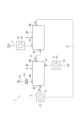
- FIG. 1 is a schematic diagram of a carbon dioxide separation and recovery system according to an embodiment.
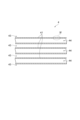
- FIG. 3 is a schematic cross-sectional view showing an enlarged part of the inside of the suction module.
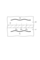
- FIG. 3 is a schematic cross-sectional view enlarging a part of the inside of the first housing.
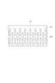
- FIG. 3 is an enlarged schematic cross-sectional view of a portion IV shown in FIG. 2.
- FIG. 3 is a schematic cross-sectional view showing an enlarged part of the inside of the detachable module. It is a schematic sectional view which enlarged a part of inside of a 2nd housing.
- FIG. 6 is an enlarged schematic cross-sectional view of the VII portion shown in FIG. 5.
- FIG. 5 is a schematic cross-sectional view showing an enlarged part of the inside of the suction module.
- FIG. 3 is a schematic cross-sectional view enlarging a part of the inside of the first housing.
- FIG. 3 is an enlarged schematic cross-sectional
- FIG. 1 is a schematic diagram of a carbon dioxide separation and recovery system according to an embodiment.
- a carbon dioxide separation and recovery system 1 shown in FIG. 1 separates and recovers carbon dioxide from a target gas TG by adsorbing and desorbing carbon dioxide (CO 2 ) to a liquid CL capable of adsorbing carbon dioxide. It is a system for The carbon dioxide separation and recovery system 1 includes a liquid supply device 2, a target gas supply device 3, an adsorption module 4, a desorption module 5, a liquid communication path 6, a gas recovery path 7, a suction device 8, and a liquid circulation system. 9.
- the liquid supply device 2 is a device for supplying the adsorption module 4 with a carbon dioxide adsorbable liquid CL that can adsorb carbon dioxide.
- the carbon dioxide adsorbable liquid CL is a salt whose molecule is designed to become a liquid at room temperature.
- any liquid may be used as long as it can adsorb and desorb carbon dioxide.
- an ionic liquid can be used as the carbon dioxide adsorbable liquid CL.
- Ionic liquids are salts whose molecules are designed to be liquid at room temperature.
- Examples of the ionic liquid used as the carbon dioxide adsorbable liquid CL include cations selected from ammonium cations, imidazolium cations, and phosphonium cations, fluorine-containing anions, cyano group-containing anions, and amino acid-derived cations.
- Examples include ionic liquids containing anions selected from anions.
- ionic liquids that combine ammonium cations and fluorine-containing anions (e.g., [N 1114 ] [TFSA], [choline] [TFSA], etc.); imidazolium cations and fluorine-containing anions.
- ammonium cations and fluorine-containing anions e.g., [N 1114 ] [TFSA], [choline] [TFSA], etc.
- imidazolium cations and fluorine-containing anions e.g., [N 1114 ] [TFSA], [choline] [TFSA], etc.
- ionic liquids that combine imidazolium cations and cyano group-containing anions (e.g., [emim][DCA], [emim][C(CN) 3 ], [emim][B(CN) ) 4 ], [bmim] [DCA], [bmim] [C(CN) 3 ], [bmim] [B(CN) 4 ], etc.); Ionic liquid that combines a phosphonium cation and an ani
- ionic liquids may be used alone or in combination of two or more. Further, solvents and additives other than the ionic liquid may be added as long as the functionality is not impaired.
- a deep eutectic solvent which is a compound that exhibits properties similar to those of an ionic liquid
- a deep eutectic solvent is a compound formed by mixing a hydrogen bond donor compound and a hydrogen bond acceptor compound, and is a compound that becomes liquid at room temperature like an ionic liquid.
- the deep eutectic solvent used as the liquid CL capable of adsorbing carbon dioxide can be selected from amide, carboxylic acid, and alcohol compounds as hydrogen bond donors, and ammonium salts and phosphonium salts as hydrogen bond acceptors. You can choose from.
- a deep eutectic solvent that is a mixture of choline chloride and urea, or a mixture of choline chloride and ethylene glycol may be used.
- the liquid supply device 2 includes, for example, a pump 21 that sends out a liquid CL capable of adsorbing carbon dioxide, and the operation of this pump 21 makes it possible to supply the liquid CL capable of adsorbing carbon dioxide to the adsorption module 4. .
- the liquid supply device 2 is connected to the adsorption module 4 via a liquid supply path 11.
- the liquid supply path 11 is formed of, for example, a tubular member such as a pipe.
- the liquid supply device 2 is connected to the liquid supply path 11 to communicate with the liquid supply path 11, and the liquid supply path 11 is connected to the adsorption module 4 to communicate with the adsorption module 4. Therefore, the carbon dioxide adsorbable liquid CL sent out from the liquid supply device 2 is supplied to the adsorption module 4 through the liquid supply path 11.
- the target gas supply device 3 is a device for supplying the target gas TG containing carbon dioxide to the adsorption module 4. Any target gas TG may be used as long as it contains carbon dioxide.
- Target gas TGs include, for example, exhaust gas from power plants such as thermal power plants and biomass power plants, exhaust gas from cement factories, exhaust gas from steel plants, exhaust gas from factories such as oil refineries and chemical factories, and hydrogen production. Exhaust gas from facilities related to ammonia production, natural gas, etc. can be used.
- the target gas supply device 3 has, for example, a compressor 31 that compresses and sends out the target gas TG, and the operation of this compressor 31 makes it possible to compress the target gas TG and supply it to the adsorption module 4. It has become.
- the target gas supply device 3 is connected to the adsorption module 4 via a gas supply path 12.
- the gas supply path 12 is formed of, for example, a tubular member such as a pipe.
- the target gas supply device 3 is connected to the gas supply path 12 to communicate with the gas supply path 12, and the gas supply path 12 is connected to the adsorption module 4 to communicate with the adsorption module 4. . Therefore, the target gas TG sent out from the target gas supply device 3 is supplied to the adsorption module 4 through the gas supply path 12.
- the adsorption module 4 is a module for separating carbon dioxide contained in the target gas TG from the target gas TG and adsorbing it into the carbon dioxide adsorbable liquid CL.
- FIG. 2 is an enlarged schematic cross-sectional view of a part of the interior of the suction module. As shown in FIGS. 1 and 2, the adsorption module 4 includes a plurality of first hollow fiber membranes 41 and a first housing 42.
- Each of the plurality of first hollow fiber membranes 41 is a hollow fiber membrane that allows gases such as carbon dioxide to pass therethrough, but not liquids such as carbon dioxide adsorbable liquid CL.
- the materials for each of the plurality of first hollow fiber membranes 41 include, for example, polypropylene, polyethylene, polymethylpentene (PMP, also known as 4-methylpentene-1 and poly(4-methylpentene-1)). Examples include polyolefin resins, silicone resins such as polydimethylsiloxane and its copolymers, and fluorine resins such as PTFE and vinylidene fluoride.
- the outer diameter of each of the plurality of first hollow fiber membranes 41 is not particularly limited, but can be, for example, 100 ⁇ m or more and 3000 ⁇ m or less, 100 ⁇ m or more and 500 ⁇ m or less, or 100 ⁇ m or more and 300 ⁇ m or less.
- the inner diameter of each of the plurality of first hollow fiber membranes 41 is not particularly limited, but can be, for example, 10 ⁇ m or more and 500 ⁇ m or less, 50 ⁇ m or more and 300 ⁇ m or less, or 80 ⁇ m or more and 200 ⁇ m or less.
- each of the plurality of first hollow fiber membranes 41 is not particularly limited, but may be, for example, 5 ⁇ m or more and 200 ⁇ m or less, 10 ⁇ m or more and 100 ⁇ m or less, or 20 ⁇ m or more and 50 ⁇ m or less.
- FIG. 3 is an enlarged schematic cross-sectional view of a part of the inside of the first housing.
- the first housing 42 houses a plurality of first hollow fiber membranes 41.
- the area within the first housing 42 is divided by a plurality of first hollow fiber membranes 41 into a first liquid phase area L1 and a first gas phase area G1. That is, the first housing 42 forms a first liquid phase region L1 and a first gas phase region G1 that are separated by the plurality of first hollow fiber membranes 41.
- the first liquid phase region L1 is a region through which the carbon dioxide adsorbable liquid CL flows
- the first gas phase region G1 is a region through which the target gas TG flows.
- the adsorption module 4 can be used as either an internal perfusion type module or an external perfusion type module.
- the outer region 43 located on the outside (outer surface side) of each of the plurality of first hollow fiber membranes 41 becomes the first liquid phase region L1, and the plurality of first hollow fiber membranes 41
- the inner region 44 located inside each of the thread membranes 41 (on the inner surface side) becomes the first gas phase region G1.
- the region between each of the plurality of first hollow fiber membranes 41 and the first housing 42 becomes the first liquid phase region L1.
- the adsorption module 4 is used as an internal perfusion type module
- the inner region 44 located inside (on the inner surface side) of each of the plurality of first hollow fiber membranes 41 becomes the first liquid phase region L1
- the plurality of first hollow fiber membranes 41 become the first liquid phase region L1.
- the outer region 43 located on the outer side (outer surface side) of each hollow fiber membrane 41 becomes the first gas phase region G1. That is, the area between each of the plurality of first hollow fiber membranes 41 and the first housing 42 becomes the first gas phase area G1.
- the first housing 42 has a first liquid supply port 45 , a first liquid discharge port 46 , a first gas supply port 47 , and a first gas discharge port 48 .
- the first liquid supply port 45 is an opening that opens the first liquid phase region L1 in order to supply the carbon dioxide adsorbable liquid CL supplied from the liquid supply device 2 to the first liquid phase region L1. That is, the first liquid supply port 45 is an opening formed in the first housing 42 at a position adjacent to the first liquid phase region L1.
- the liquid supply device 2 is communicated with the first liquid phase region L1 through the first liquid supply port 45, and can supply the carbon dioxide adsorbable liquid CL to the first liquid phase region L1 through the first liquid supply port 45. It is possible.
- the first liquid discharge port 46 opens the first liquid phase region L1 in order to discharge the carbon dioxide adsorbable liquid CL supplied to the first liquid phase region L1 from the first liquid phase region L1 to the liquid communication path 6. It is an opening. That is, the first liquid discharge port 46 is an opening different from the first liquid supply port 45, which is formed in the first housing 42 at a position adjacent to the first liquid phase region L1. The first liquid phase region L1 is communicated with the liquid communication path 6 through the first liquid discharge port 46.
- the first gas supply port 47 is an opening that opens the first gas phase region G1 in order to supply the target gas TG supplied from the target gas supply device 3 to the first gas phase region G1. That is, the first gas supply port 47 is an opening formed in the first housing at a position adjacent to the first gas phase region G1.
- the target gas supply device 3 is communicated with the first gas phase region G1 through the first gas supply port 47, and is capable of supplying the target gas TG to the first gas phase region G1 through the first gas supply port 47. It has become.
- the first gas discharge port 48 is an opening that opens the first gas phase region G1 in order to discharge the target gas TG supplied to the first gas phase region G1 from the first gas phase region G1. That is, the first gas discharge port 48 is an opening different from the first gas supply port 47, which is formed in the first housing at a position adjacent to the first gas phase region G1.
- the first gas phase region G1 is open to the outside of the adsorption module 4 through the first gas outlet 48.
- the gas exhaust path 13 is connected to the first gas exhaust port 48 .
- the gas exhaust path 13 is formed of, for example, a tubular member such as a pipe.
- the gas exhaust path 13 is connected to the first gas exhaust port 48, thereby communicating with the first gas phase region G1. Therefore, the target gas discharged from the first gas phase region G1 is discharged to the outside of the carbon dioxide separation and recovery system 1 through the gas discharge path 13.
- a flow rate regulating valve 14 that adjusts (restricts) the flow rate of the target gas TG is attached to the gas discharge path 13 so that the target gas TG is maintained at a high pressure state in the first gas phase region G1.
- FIG. 4 is an enlarged schematic cross-sectional view of the IV portion shown in FIG. 2.
- each of the plurality of first hollow fiber membranes 41 includes a dense layer 411 and a porous layer 412.
- the dense layer 411 is a layer without porosity, that is, a non-porous layer.
- the layer without porosity is, for example, a layer without pores through which the carbon dioxide adsorbable liquid CL can pass. That is, the dense layer 411 does not need to have holes through which the carbon dioxide adsorbable liquid CL can pass.
- the pores through which the carbon dioxide adsorbable liquid CL can pass are, for example, pores whose minimum pore diameter is larger than the molecules constituting the carbon dioxide adsorbable liquid CL. In this case, the dense layer 411 may have holes through which the carbon dioxide adsorbable liquid CL cannot pass.
- a layer without porosity is, for example, a layer without pores having a pore diameter of 0.01 ⁇ m or more, 0.005 ⁇ m or more, or 0.001 ⁇ m or more. That is, the dense layer 411 does not need to have pores with a pore diameter of 0.01 ⁇ m or more, 0.005 ⁇ m or more, or 0.001 ⁇ m or more. Note that if the hole is not perfectly spherical, this hole diameter is, for example, the maximum hole diameter of the hole. In this case, the dense layer 411 may have pores having a diameter of less than 0.01 ⁇ m, less than 0.005 ⁇ m, or less than 0.001 ⁇ m.
- the dense layer 411 may be located at any position of each of the plurality of first hollow fiber membranes 41 as long as it is located outside (on the outer surface side) of the porous layer 412. From the viewpoint that the dense layer 411 can be easily formed and that each of the plurality of first hollow fiber membranes 41 is difficult to wet when the adsorption module 4 is an external perfusion type module, the dense layer 411 is formed by, for example, a plurality of first hollow fiber membranes 41. It may be formed on each outer surface of one hollow fiber membrane 41.
- the dense layer 411 is not formed on the outer surface of each of the plurality of first hollow fiber membranes 41, a layer similar to the porous layer 412, for example, may be formed on the outside (outer surface side) of the dense layer 411. may have been done.
- the porous layer 412 is a porous layer located inside the dense layer 411.
- the porous layer 412 also functions as a layer that supports the dense layer 411.
- the porous layer is, for example, a layer that has pores through which the carbon dioxide adsorbable liquid CL can pass.
- the porous layer is, for example, a layer having pores with a pore diameter of 0.01 ⁇ m or more, 0.05 ⁇ m or more, or 0.1 ⁇ m or more. Note that if the hole is not perfectly spherical, this hole diameter is, for example, the maximum hole diameter of the hole.
- the porous layer 412 is formed, for example, into a sponge shape.
- the porosity of the porous layer 412 is not particularly limited.
- the porosity is the ratio of pores in a target layer such as the porous layer 412.
- the porosity can be determined, for example, by measuring the weight and volume of a certain amount of the hollow fiber membrane and converting it from the apparent density and true density. From the viewpoint of securing membrane area and increasing gas exchange ability, the porosity of the porous layer 412 may be, for example, 5% or more, 10% or more, or 20% or more.
- the supporting force of the dense layer 411 by the porous layer 412 can be ensured sufficiently, and the liquid CL capable of adsorbing carbon dioxide becomes difficult to enter the porous layer 412, and the porous layer 412 becomes difficult to get wet.
- the porosity of the porous layer 412 may be, for example, 60% or less, 50% or less, or 40% or less. From these viewpoints, the porosity of the porous layer 412 may be, for example, 5% or more and 60% or less, 10% or more and 50% or less, or 20% or more and 40% or less.
- one of the indicators for separating carbon dioxide from the carbon dioxide adsorbable liquid CL is the separation coefficient ⁇ of carbon dioxide with respect to nitrogen.
- the separation coefficient ⁇ is determined by measuring the carbon dioxide and nitrogen permeation rates based on ASTM D-1434, and then calculating the ratio of the carbon dioxide permeation rate to the nitrogen permeation rate (carbon dioxide permeation rate/nitrogen permeation rate). speed). Since the separation coefficient ⁇ of carbon dioxide with respect to nitrogen in each of the plurality of first hollow fiber membranes 41 is larger than 1, carbon dioxide can be separated from the liquid CL capable of adsorbing carbon dioxide.
- the separation coefficient ⁇ of carbon dioxide with respect to nitrogen in each of the plurality of first hollow fiber membranes 41 is not particularly limited as long as it is larger than 1.
- the separation coefficient ⁇ of carbon dioxide with respect to nitrogen in each of the plurality of first hollow fiber membranes 41 is, for example, 2 or more. , 8 or more, or 10 or more.
- the separation coefficient ⁇ of carbon dioxide with respect to nitrogen in each of the plurality of first hollow fiber membranes 41 is, for example, 20 or less, 17 or less, or 15 or less. From these viewpoints, the separation coefficient ⁇ of carbon dioxide with respect to nitrogen in each of the plurality of first hollow fiber membranes 41 may be, for example, 2 or more and 20 or less, 8 or more and 17 or less, or 10 or more and 15 or less.
- the desorption module 5 is a module for desorbing and recovering carbon dioxide from the carbon dioxide adsorbable liquid CL on which carbon dioxide has been adsorbed in the adsorption module 4.
- FIG. 5 is an enlarged schematic cross-sectional view of a part of the inside of the detachable module.
- the desorption module 5 includes a plurality of second hollow fiber membranes 51 and a second housing 52.
- Each of the plurality of second hollow fiber membranes 51 is a hollow fiber-like membrane that permeates gases such as carbon dioxide but does not permeate liquids such as carbon dioxide adsorbable liquid CL. It is a membrane.
- the materials for each of the plurality of second hollow fiber membranes 51 include, for example, polyolefin resins such as polypropylene, polyethylene, and polymethylpentene, silicone resins such as polydimethylsiloxane and its copolymers, PTFE, and vinylidene fluoride. Examples include fluororesins.
- the outer diameter of each of the plurality of second hollow fiber membranes 51 is not particularly limited, but can be, for example, 100 ⁇ m or more and 3000 ⁇ m or less, 100 ⁇ m or more and 500 ⁇ m or less, or 100 ⁇ m or more and 300 ⁇ m or less.
- the inner diameter of each of the plurality of second hollow fiber membranes 51 is not particularly limited, but can be, for example, 10 ⁇ m or more and 500 ⁇ m or less, 50 ⁇ m or more and 300 ⁇ m or less, or 80 ⁇ m or more and 200 ⁇ m or less.
- each of the plurality of second hollow fiber membranes 51 is not particularly limited, but may be, for example, 5 ⁇ m or more and 200 ⁇ m or less, 10 ⁇ m or more and 100 ⁇ m or less, or 20 ⁇ m or more and 50 ⁇ m or less.
- FIG. 6 is an enlarged schematic cross-sectional view of a part of the inside of the second housing.
- the second housing 52 accommodates a plurality of second hollow fiber membranes 51.
- the area within the second housing 52 is divided by a plurality of second hollow fiber membranes 51 into a second liquid phase area L2 and a second gas phase area G2. That is, the second housing 52 forms a second liquid phase region L2 and a second gas phase region G2 that are separated by the plurality of second hollow fiber membranes 51.
- the second liquid phase region L2 is a region in which the carbon dioxide adsorbable liquid CL flows
- the second gas phase region G2 is a region in which carbon dioxide desorbed from the carbon dioxide adsorbable liquid CL flows.
- the detachable module 5 can be used as either an internal perfusion type module or an external perfusion type module.
- the desorption module 5 is used as an external perfusion type module
- the outer region 53 located on the outside (outer surface side) of each of the plurality of second hollow fiber membranes 51 becomes the second liquid phase region L2, and the plurality of second hollow fiber membranes 51 serve as the second liquid phase region L2.
- the inner region 54 located inside each of the thread membranes 51 (on the inner surface side) becomes the second gas phase region G2.
- the region between each of the plurality of second hollow fiber membranes 51 and the second housing 52 becomes the second liquid phase region L2.
- the desorption module 5 is used as an internal perfusion type module
- the inner region 54 located inside each of the plurality of second hollow fiber membranes 51 (inner surface side) becomes the second liquid phase region L2
- the plurality of second hollow fiber membranes 51 become the second liquid phase region L2.
- the outer region 53 located on the outer side (outer surface side) of each of the two hollow fiber membranes 51 becomes the second gas phase region G2. That is, the region between each of the plurality of second hollow fiber membranes 51 and the second housing 52 becomes the second gas phase region G2.
- the second housing 52 has a second liquid supply port 55, a second liquid discharge port 56, and a second gas discharge port 57.
- the second liquid supply port 55 is an opening that opens the second liquid phase region L2 in order to supply the carbon dioxide adsorbable liquid CL from the liquid communication path 6 to the second liquid phase region L2. That is, the second liquid supply port 55 is an opening formed in the second housing 52 at a position adjacent to the second liquid phase region L2.
- the liquid communication path 6 communicates with the second liquid phase region L2 through the second liquid supply port 55.
- the second liquid outlet 56 is an opening that opens the second liquid phase region L2 in order to discharge the carbon dioxide adsorbable liquid CL supplied to the second liquid phase region L2 from the second liquid phase region L2 to the liquid circulation path 9.
- the second liquid outlet 56 is an opening formed in the second housing 52 at a position adjacent to the second liquid phase region L2, and is different from the second liquid supply port 55.
- the second liquid phase region L2 is connected to the liquid circulation path 9 through the second liquid outlet 56.
- the second gas outlet 57 is an opening that opens the second gas phase region G2 in order to discharge carbon dioxide desorbed from the carbon dioxide adsorbable liquid CL from the second liquid phase region L2. That is, the second gas discharge port 57 is an opening formed in the second housing 52 at a position adjacent to the second gas phase region G2. The second gas phase region G2 is communicated with the gas recovery path 7 through the second gas discharge port 57.
- FIG. 7 is an enlarged schematic cross-sectional view of the VII portion shown in FIG. 5.
- each of the plurality of second hollow fiber membranes 51 includes a dense layer 511 and a porous layer 512.
- the dense layer 511 is a layer without porosity, that is, a non-porous layer. Like the dense layer 411, the dense layer 511 does not need to have holes through which the carbon dioxide adsorbable liquid CL can pass. Further, like the dense layer 411, the dense layer 511 does not need to have pores with a pore diameter of 0.01 ⁇ m or more, 0.005 ⁇ m or more, or 0.001 ⁇ m or more. Note that if the hole is not perfectly spherical, this hole diameter is, for example, the maximum hole diameter of the hole. In this case, the dense layer 511 may have pores having a diameter of less than 0.01 ⁇ m, less than 0.005 ⁇ m, or less than 0.001 ⁇ m.
- the dense layer 511 may be located at any position in each of the plurality of second hollow fiber membranes 51 as long as it is located outside (on the outer surface side) of the porous layer 512. Further, like the dense layer 411, the dense layer 511 may be formed, for example, on the outer surface of each of the plurality of second hollow fiber membranes 51. Note that if the dense layer 511 is not formed on the outer surface of each of the plurality of second hollow fiber membranes 51, a layer similar to the porous layer 512, for example, may be formed on the outside (outer surface side) of the dense layer 511. may have been done.
- the porous layer 512 is a layer located inside the dense layer 511 and has porosity.
- the porous layer 512 also functions as a layer that supports the dense layer 5411.
- the porous layer 512 is formed, for example, into a sponge shape.
- the porosity of the porous layer 512 is not particularly limited. From the same viewpoint as the porous layer 412, the porosity of the porous layer 512 may be, for example, 5% or more, 10% or more, or 20% or more. On the other hand, from the same viewpoint as the porous layer 412, the porosity of the porous layer 512 may be, for example, 60% or less, 50% or less, or 40% or less. From these viewpoints, the porosity of the porous layer 512 may be, for example, 5% or more and 60% or less, 10% or more and 50% or less, or 20% or more and 40% or less.
- the separation coefficient ⁇ of carbon dioxide with respect to nitrogen in each of the plurality of second hollow fiber membranes 51 is not particularly limited as long as it is larger than 1. From the same viewpoint as each of the plurality of first hollow fiber membranes 41, the separation coefficient ⁇ of carbon dioxide with respect to nitrogen in each of the plurality of second hollow fiber membranes 51 is, for example, 2 or more, 8 or more, or 10 or more. You can. On the other hand, from the same viewpoint as each of the plurality of first hollow fiber membranes 41, the separation coefficient ⁇ of carbon dioxide with respect to nitrogen in each of the plurality of second hollow fiber membranes 51 is, for example, 20 or less, 17 or less, or 15 or less. It may be. From these viewpoints, the separation coefficient ⁇ of carbon dioxide with respect to nitrogen in each of the plurality of second hollow fiber membranes 51 may be, for example, 2 or more and 20 or less, 8 or more and 17 or less, or 10 or more and 15 or less.
- the liquid communication path 6 is connected to the adsorption module 4 and the desorption module 5, and communicates the first liquid phase region L1 of the adsorption module 4 with the second liquid phase region L2 of the desorption module 5.
- the liquid communication path 6 is formed of, for example, a tubular member such as a pipe.
- the liquid communication path 6 is connected to the first liquid discharge port 46 of the first housing 42 at one end thereof, thereby communicating with the first liquid phase region L1. Further, the other end of the liquid communication path 6 is connected to the second liquid supply port 55 of the second housing 52, thereby communicating with the second liquid phase region L2. Therefore, the carbon dioxide adsorbable liquid CL discharged from the first liquid phase region L1 of the adsorption module 4 is supplied to the second liquid phase region L2 of the desorption module 5 through the liquid communication path 6.
- the gas recovery path 7 is connected to the desorption module 5 and communicates with the second gas phase region G2 of the desorption module 5.
- the gas recovery path 7 is formed of, for example, a tubular member such as a pipe.
- the gas recovery path 7 is connected to the second gas exhaust port 57 of the second housing 52, thereby communicating with the second gas phase region G2. Therefore, the carbon dioxide that has been desorbed from the carbon dioxide adsorbable liquid CL in the desorption module 5 and permeated through each of the plurality of second hollow fiber membranes 51 is recovered through the gas recovery path 7 .
- the suction device 8 is a device provided in the gas recovery path 7 to reduce the pressure in the second gas phase region G2 of the desorption module 5 and recover carbon dioxide.
- the suction device 8 has, for example, a vacuum pump 81 that sends out gas, and the operation of the vacuum pump 81 causes gas such as carbon dioxide to be transferred from the desorption module 5 side to the opposite side of the desorption module 5 in the gas recovery path 7. It is possible to send it out, reduce the pressure in the second gas phase region G2, and recover carbon dioxide from the second gas phase region G2.
- the liquid circulation path 9 communicates with the desorption module 5 and the liquid supply device 2 in order to supply the carbon dioxide adsorbable liquid CL discharged from the desorption module 5 to the adsorption module 4.
- the liquid circulation path 9 is formed of, for example, a tubular member such as a pipe.
- One tip of the liquid circulation path 9 is connected to the second liquid discharge port 56 of the second housing 52, so that the liquid circulation path 9 communicates with the second liquid phase region L2.
- the other end of the liquid circulation path 9 is connected to the liquid supply device 2, so that the liquid circulation path 9 communicates with the liquid supply device 2. Therefore, the carbon dioxide adsorbable liquid CL discharged from the second liquid phase region L2 of the desorption module 5 is supplied to the liquid supply device 2 through the liquid circulation path 9.
- a liquid CL capable of adsorbing carbon dioxide is supplied from the liquid supply device 2 to the first liquid phase region L1 of the adsorption module 4. That is, by operating the pump 21 of the liquid supply device 2, the carbon dioxide adsorbable liquid CL is supplied to the first liquid phase region L1. Further, the target gas TG is supplied from the target gas supply device 3 to the first gas phase region G1 of the adsorption module 4. That is, by operating the compressor 31 of the target gas supply device 3, the target gas TG is compressed and supplied to the adsorption module 4.
- the flow rate of the target gas TG at the first gas outlet 48 is adjusted by the flow rate regulating valve 14 so that the target gas TG is maintained at a high pressure state in the first gas phase region G1.
- the second gas phase region G2 of the desorption module 5 is depressurized by the suction device 8. That is, by operating the vacuum pump 81, gas is sent from the desorption module 5 side to the opposite side of the desorption module 5 in the gas recovery path 7, thereby reducing the pressure in the second gas phase region G2.
- carbon dioxide contained in the target gas TG supplied to the first gas phase region G1 passes through each of the plurality of first hollow fiber membranes 41 and is supplied to the first liquid phase region L1. It is adsorbed by the carbon dioxide adsorbable liquid CL. Thereby, carbon dioxide is separated from the target gas TG. Then, the carbon dioxide adsorbable liquid CL that has adsorbed carbon dioxide is discharged from the first liquid phase region L1 to the liquid communication path 6.
- the target gas TG from which carbon dioxide has been separated is discharged from the first gas phase region G1 to the outside of the carbon dioxide separation and recovery system 1 through the gas discharge path 13.
- the carbon dioxide adsorbable liquid CL discharged from the first liquid phase region L1 to the liquid communication path 6 is supplied from the liquid communication path 6 to the second liquid phase region L2 of the desorption module 5.
- the carbon dioxide adsorbed in the carbon dioxide adsorbable liquid CL supplied from the liquid communication path 6 to the second liquid phase region L2 is removed. permeates through each of the plurality of second hollow fiber membranes 51.
- the carbon dioxide adsorbable liquid CL from which carbon dioxide has been desorbed is discharged from the second liquid phase region L2 to the liquid circulation path 9.
- carbon dioxide that has passed through each of the plurality of second hollow fiber membranes 51 is discharged from the second gas phase region G2 to the gas recovery path 7. Then, carbon dioxide is recovered from the second gas phase region G2 through the gas recovery path 7.
- the liquid CL capable of adsorbing carbon dioxide is supplied from the liquid supply device 2 to the first liquid phase region L1
- the liquid CL capable of adsorbing carbon dioxide is supplied from the target gas supply device 3 to the first gas phase region L1.
- the target gas TG is supplied to the region G1
- the adsorption module 4 carbon dioxide contained in the target gas TG permeates each of the plurality of first hollow fiber membranes 41 and is adsorbed by the carbon dioxide adsorbable liquid CL.
- carbon dioxide can be separated from the target gas TG and adsorbed into the carbon dioxide adsorbable liquid CL.
- the carbon dioxide adsorbable liquid CL on which carbon dioxide has been adsorbed in the adsorption module 4, is supplied to the second liquid phase region L2 of the desorption module 5 through the liquid communication path 6.
- carbon dioxide is desorbed from the carbon dioxide adsorbable liquid CL supplied to the second liquid phase region L2, and the carbon dioxide passes through each of the plurality of second hollow fiber membranes 51.
- the carbon dioxide that has permeated through each of the plurality of second hollow fiber membranes 51 is recovered through the gas recovery path 7 that communicates with the second gas phase region G2. Thereby, carbon dioxide can be recovered from the carbon dioxide adsorbable liquid CL.
- each of the plurality of first hollow fiber membranes 41 of the adsorption module 4 and each of the plurality of second hollow fiber membranes 51 of the desorption module 5 are in an environment where they are easily wetted because they come into contact with the carbon dioxide adsorbable liquid CL.
- each of the plurality of first hollow fiber membranes 41 has a dense layer 411 that does not have porosity, and a porous layer 412 that is located inside the dense layer 411 and has porosity.
- each of the plurality of second hollow fiber membranes 51 has a dense layer 511 that does not have porosity, and a porous layer 512 that is located inside the dense layer 511 and has porosity.
- the dense layer 411 and the dense layer 511 do not have porosity, they have a structure in which the carbon dioxide adsorbable liquid CL is difficult to enter and wet. Therefore, early deterioration of gas exchange ability can be suppressed.
- the dense layer 411 and the dense layer 511 do not have porosity, the first liquid phase region is caused by gas passing through each of the plurality of first hollow fiber membranes 41 and each of the plurality of second hollow fiber membranes 51. Generation of bubbles in L1 and second liquid phase region L2 can be suppressed.
- the range of choices for the carbon dioxide adsorbable liquid CL is expanded, so that the optimal carbon dioxide adsorbable liquid CL can be selected according to the operating conditions, required performance, etc. of the carbon dioxide separation and recovery system 1.
- the dense layer 411 and the dense layer 511 which do not have porosity, thin. Strength decreases.
- the dense layer 411 and the dense layer 511 can be supported from the inside by the porous layer 412 and the porous layer 512, as the dense layer 411 and the dense layer 511 become thinner, the plurality of first hollow fiber membranes 41 It is possible to suppress the strength of each of the second hollow fiber membranes 51 from decreasing. As a result, the dense layer 411 and the dense layer 511 are made thinner and the gas exchange ability is enhanced, while the strength of each of the plurality of first hollow fiber membranes 41 and the plurality of second hollow fiber membranes 51 is suppressed from decreasing. can do.
- the carbon dioxide adsorbable liquid CL is an ionic liquid
- the carbon dioxide that has permeated through each of the plurality of first hollow fiber membranes 41 can be appropriately converted into carbon dioxide.
- Carbon dioxide can be adsorbed to the adsorbable liquid CL, and in the desorption module 5, carbon dioxide can be appropriately desorbed from the carbon dioxide adsorbable liquid CL and permeated through each of the plurality of second hollow fiber membranes 51.
- the dense layer 411 and the dense layer 511 do not have holes through which the carbon dioxide adsorbable liquid CL can pass. Wetting of each of the two hollow fiber membranes 51 can be further suppressed.
- the carbon dioxide adsorbable liquid CL can be suppressed from passing through each of the plurality of first hollow fiber membranes 41 and each of the plurality of second hollow fiber membranes 51. Thereby, it is possible to further suppress each of the plurality of first hollow fiber membranes 41 and each of the plurality of second hollow fiber membranes 51 from getting wet.
- the dense layer 411 and the dense layer 511 are formed on the outer surface of each of the plurality of first hollow fiber membranes 41 and each of the plurality of second hollow fiber membranes 51. , it is easy to form the dense layer 411 and the dense layer 511. Moreover, when the adsorption module 4 and the desorption module 5 are external perfusion type modules, each of the plurality of first hollow fiber membranes 41 and each of the plurality of second hollow fiber membranes 51 are wetted with the carbon dioxide adsorbable liquid CL. This makes it possible to maintain gas exchange ability for a longer period of time.
- the membrane area can be secured to allow gas exchange. ability can be improved.
- the porosity of the porous layer 412 and the porous layer 512 is 60% or less, 50% or less, or 40% or less, the dense layer 411 and the dense layer 511 due to the porous layer 412 and the porous layer 512 Sufficient supporting capacity can be ensured.
- liquid CL capable of adsorbing carbon dioxide becomes difficult to enter the porous layer 412 and the porous layer 512, and the porous layer 412 and the porous layer 512 become difficult to wet, it is possible to suppress the early deterioration of gas exchange performance. can.
- each of the plurality of first hollow fiber membranes 41 and the plurality of second hollow fiber membranes 51 each have the dense layer 411 and the dense layer 511, so that the plurality of first hollow fiber membranes
- the separation coefficient ⁇ of carbon dioxide with respect to nitrogen of each of the membranes 41 and the plurality of second hollow fiber membranes 51 can be set to 2 or more. Since the separation coefficient ⁇ of carbon dioxide with respect to nitrogen of each of the plurality of first hollow fiber membranes 41 and the plurality of second hollow fiber membranes 51 is 2 or more, 8 or more, or 10 or more, the carbon dioxide is accompanied by carbon dioxide.
- the first liquid phase region L1 is a region located outside each of the plurality of first hollow fiber membranes 41
- the second liquid phase region L2 is a region located outside each of the plurality of first hollow fiber membranes 41.
- the adsorption module 4 and the desorption module 5 become external perfusion type modules.
- the porous layer 412 and the porous layer 512 are less likely to get wet with the liquid CL capable of adsorbing carbon dioxide, so that the gas exchange ability can be maintained for a longer period of time.
- the pressure loss of the carbon dioxide adsorbable liquid CL flowing through the adsorption module 4 and the desorption module 5 can be reduced.
- the target gas supply device 3 includes a compressor 31 for compressing the target gas TG and supplying the compressed target gas TG to the first gas phase region G1.
- Carbon dioxide contained in TG can easily permeate each of the plurality of first hollow fiber membranes 41. Thereby, carbon dioxide is easily separated from the target gas TG and adsorbed into the carbon dioxide adsorbable liquid CL.
- the adsorption module 4 includes a first housing 42 that accommodates a plurality of first hollow fiber membranes 41 and forms a first liquid phase region L1 and a first gas phase region G1. Therefore, a first liquid phase region L1 and a first gas phase region G1 are formed within the first housing 42. Since the first housing 42 has the first liquid supply port 45 and the first liquid discharge port 46, it is possible to supply the carbon dioxide adsorbable liquid CL supplied from the liquid supply device 2 to the first liquid phase region L1. At the same time, the carbon dioxide adsorbable liquid CL supplied to the first liquid phase region L1 can be discharged from the first liquid phase region L1 to the liquid communication path 6.
- the target gas TG supplied from the target gas supply device 3 can be supplied to the first gas phase region G1.
- the target gas TG supplied to the first gas phase region G1 can be discharged from the first gas phase region G1.
- the desorption module 5 has a second housing 52 that accommodates the plurality of second hollow fiber membranes 51 and forms a second liquid phase region L2 and a second gas phase region G2. Therefore, a second liquid phase region L2 and a second gas phase region G2 are formed within the second housing 52. Since the second housing 52 has the second liquid supply port 55 and the second liquid discharge port 56, the carbon dioxide adsorbable liquid CL supplied from the adsorption module 4 through the liquid communication path 6 is transferred to the second liquid phase region L2. At the same time, the carbon dioxide adsorbable liquid CL supplied to the second liquid phase region L2 can be discharged from the second liquid phase region L2.
- the second housing 52 since the second housing 52 has the second gas exhaust port 57, carbon dioxide can be discharged and recovered from the second gas phase region G2. As a result, it is possible to continue supplying the liquid CL capable of adsorbing carbon dioxide to the second liquid phase region L2 and continue recovering carbon dioxide from the second gas phase region G2, so that carbon dioxide can be recovered from the liquid CL capable of adsorbing carbon dioxide over a long period of time. can be detached and recovered.
- each of the plurality of first hollow fiber membranes 41 and each of the plurality of second hollow fiber membranes 51 contains an olefin resin, the plurality of first hollow fiber membranes 41 High hydrophobicity can be imparted to each and each of the plurality of second hollow fiber membranes 51.
- the liquid CL capable of adsorbing carbon dioxide it becomes difficult for the liquid CL capable of adsorbing carbon dioxide to enter the porous layer 412 and the porous layer 512, and the porous Layer 412 and porous layer 512 become less wettable.
- the dense layer 411 and the dense layer 511 have a structure in which the carbon dioxide adsorbable liquid CL does not easily enter and get wet because they do not have porosity, but due to aging deterioration, the above structure of the dense layer 411 and the dense layer 511 has deteriorated There is a possibility that it will collapse. However, even if the structures of the dense layer 411 and the dense layer 511 collapse due to aged deterioration, the dense layer The liquid CL capable of adsorbing carbon dioxide becomes difficult to enter into the dense layer 411 and the dense layer 511, and the dense layer 411 and the dense layer 511 become difficult to wet.
- the carbon dioxide adsorbable liquid CL discharged from the desorption module 5 can be supplied to the adsorption module 4 through the liquid circulation path 9, so that the usage amount of the carbon dioxide adsorbable liquid CL is can be reduced.
- the liquid CL capable of adsorbing carbon dioxide is supplied from the liquid supply device 2 to the first liquid phase region L1
- the liquid CL capable of adsorbing carbon dioxide is supplied from the target gas supply device 3 to the first liquid phase region L1. Since carbon dioxide is recovered from the second gas phase region G2 by supplying the target gas to the gas phase region G1 and reducing the pressure in the second gas phase region G2, it is possible to suppress an early decrease in gas exchange performance.
- each of the plurality of first hollow fiber membranes and each of the plurality of second hollow fiber membranes may be the same or different.
- the dense layer and porous layer of each of the plurality of first hollow fiber membranes and the dense layer and porous layer of each of the plurality of second hollow fiber membranes may be the same, or each They may be different.
- One aspect of the present invention can be used as a carbon dioxide separation and recovery system and a carbon dioxide separation and recovery method.
- Second liquid supply port 56...Second liquid discharge port, 57...Second gas discharge port, 6...Liquid communication path, 7...Gas recovery path, 8...Suction device, 81...Vacuum pump, 9...Liquid circulation path, 11...Liquid supply path, 12... Gas supply path, 13... Gas discharge path, 14... Flow rate adjustment valve, G1... First gas phase region, G2... Second gas phase region, L1... First liquid phase region, L2... Second liquid phase region, CL...Liquid capable of adsorbing carbon dioxide, TG...Target gas.
Landscapes
- Chemical & Material Sciences (AREA)
- Chemical Kinetics & Catalysis (AREA)
- Engineering & Computer Science (AREA)
- Water Supply & Treatment (AREA)
- Analytical Chemistry (AREA)
- General Chemical & Material Sciences (AREA)
- Oil, Petroleum & Natural Gas (AREA)
- Separation Using Semi-Permeable Membranes (AREA)
Priority Applications (1)
| Application Number | Priority Date | Filing Date | Title |
|---|---|---|---|
| JP2024501187A JP7658505B2 (ja) | 2022-09-15 | 2023-09-07 | 二酸化炭素分離回収システム及び二酸化炭素分離回収方法 |
Applications Claiming Priority (2)
| Application Number | Priority Date | Filing Date | Title |
|---|---|---|---|
| JP2022-146960 | 2022-09-15 | ||
| JP2022146960 | 2022-09-15 |
Publications (1)
| Publication Number | Publication Date |
|---|---|
| WO2024058048A1 true WO2024058048A1 (ja) | 2024-03-21 |
Family
ID=90274875
Family Applications (1)
| Application Number | Title | Priority Date | Filing Date |
|---|---|---|---|
| PCT/JP2023/032700 Ceased WO2024058048A1 (ja) | 2022-09-15 | 2023-09-07 | 二酸化炭素分離回収システム及び二酸化炭素分離回収方法 |
Country Status (2)
| Country | Link |
|---|---|
| JP (1) | JP7658505B2 (https=) |
| WO (1) | WO2024058048A1 (https=) |
Cited By (3)
| Publication number | Priority date | Publication date | Assignee | Title |
|---|---|---|---|---|
| WO2025244133A1 (ja) * | 2024-05-24 | 2025-11-27 | 国立大学法人東北大学 | 脱水蒸気ガスの製造方法、co2の回収方法、co2とco2吸収剤との化学反応物の製造方法、co2ガス回収システム、及びイオン液体膜 |
| JP7826580B1 (ja) * | 2025-07-24 | 2026-03-09 | Anaホールディングス株式会社 | 二酸化炭素量制御装置および二酸化炭素量制御システム |
| JP7844764B1 (ja) * | 2025-07-24 | 2026-04-13 | Anaホールディングス株式会社 | 二酸化炭素量制御装置および二酸化炭素量制御システム |
Citations (4)
| Publication number | Priority date | Publication date | Assignee | Title |
|---|---|---|---|---|
| JP2002363581A (ja) * | 2001-06-06 | 2002-12-18 | Tsukishima Kikai Co Ltd | メタン濃縮装置 |
| US20140096682A1 (en) * | 2012-10-04 | 2014-04-10 | Phillips 66 Company | Fluorinated surfactants and stabilization of polytetrafluoroethylene (ptfe) particles in hollow fiber spin solutions |
| JP2017145219A (ja) * | 2016-02-18 | 2017-08-24 | 国立大学法人佐賀大学 | 共融混合物及びその用途 |
| CN113289456A (zh) * | 2021-05-21 | 2021-08-24 | 浙江工业大学 | 一种用于气体硫碳协同脱除提质的深共晶溶剂及其制备与应用方法 |
Family Cites Families (1)
| Publication number | Priority date | Publication date | Assignee | Title |
|---|---|---|---|---|
| CN112337322A (zh) * | 2020-11-11 | 2021-02-09 | 天津工业大学 | 一种聚4-甲基-1-戊烯中空纤维膜及其制备方法 |
-
2023
- 2023-09-07 JP JP2024501187A patent/JP7658505B2/ja active Active
- 2023-09-07 WO PCT/JP2023/032700 patent/WO2024058048A1/ja not_active Ceased
Patent Citations (4)
| Publication number | Priority date | Publication date | Assignee | Title |
|---|---|---|---|---|
| JP2002363581A (ja) * | 2001-06-06 | 2002-12-18 | Tsukishima Kikai Co Ltd | メタン濃縮装置 |
| US20140096682A1 (en) * | 2012-10-04 | 2014-04-10 | Phillips 66 Company | Fluorinated surfactants and stabilization of polytetrafluoroethylene (ptfe) particles in hollow fiber spin solutions |
| JP2017145219A (ja) * | 2016-02-18 | 2017-08-24 | 国立大学法人佐賀大学 | 共融混合物及びその用途 |
| CN113289456A (zh) * | 2021-05-21 | 2021-08-24 | 浙江工业大学 | 一种用于气体硫碳协同脱除提质的深共晶溶剂及其制备与应用方法 |
Cited By (3)
| Publication number | Priority date | Publication date | Assignee | Title |
|---|---|---|---|---|
| WO2025244133A1 (ja) * | 2024-05-24 | 2025-11-27 | 国立大学法人東北大学 | 脱水蒸気ガスの製造方法、co2の回収方法、co2とco2吸収剤との化学反応物の製造方法、co2ガス回収システム、及びイオン液体膜 |
| JP7826580B1 (ja) * | 2025-07-24 | 2026-03-09 | Anaホールディングス株式会社 | 二酸化炭素量制御装置および二酸化炭素量制御システム |
| JP7844764B1 (ja) * | 2025-07-24 | 2026-04-13 | Anaホールディングス株式会社 | 二酸化炭素量制御装置および二酸化炭素量制御システム |
Also Published As
| Publication number | Publication date |
|---|---|
| JPWO2024058048A1 (https=) | 2024-03-21 |
| JP7658505B2 (ja) | 2025-04-08 |
Similar Documents
| Publication | Publication Date | Title |
|---|---|---|
| WO2024058048A1 (ja) | 二酸化炭素分離回収システム及び二酸化炭素分離回収方法 | |
| EP0751815B1 (en) | Method for gas absorption across a membrane | |
| US11519079B2 (en) | Electrochemical carbon dioxide converter and liquid regenerator | |
| US20160206993A1 (en) | Closed cycle continuous membrane ionic liquids absorption/desorption process for co2 capture | |
| Lin et al. | Absorption of carbon dioxide by mixed piperazine–alkanolamine absorbent in a plasma-modified polypropylene hollow fiber contactor | |
| US9072987B2 (en) | Method and apparatus for desorption using a microporous membrane operated in wetted mode | |
| US10828599B2 (en) | Method of extracting components of gas mixtures by pertraction on nanoporous membranes | |
| EP3572140A2 (en) | Electrochemical carbon dioxide converter and liquid regenerator | |
| JP6715575B2 (ja) | 二酸化炭素分離方法及び二酸化炭素分離装置 | |
| JP2004261757A (ja) | 環境浄化循環型水電解装置 | |
| JP3999423B2 (ja) | 液体膜による炭酸ガス分離・除湿方法およびその装置 | |
| US20210268445A1 (en) | Method for humidifying facilitated-transport membranes | |
| EP2942099A1 (en) | Adsorptive permeable hollow fiber membrane, manufacturing method therefor and gas adsorbing and desorbing separation system using same | |
| CN104797326A (zh) | 用于通过气体解吸进行热整合液体吸收剂再生的工艺和设备 | |
| Simons | Membrane technologies for CO2 capture | |
| WO2022014469A1 (ja) | 分離システム | |
| Kartohardjono et al. | Effects of absorbent flow rate on CO2 absorption through a super hydrophobic hollow fiber membrane contactor | |
| US8357228B2 (en) | Gas purification method | |
| WO2021186974A1 (ja) | ガス分離方法およびゼオライト膜 | |
| KR101763144B1 (ko) | 분리막 접촉기용 물리적 흡수제 및 이를 이용한 이산화탄소의 분리방법 | |
| RU2672452C1 (ru) | Мембранный контактор для очистки природных и технологических газов от кислых компонентов | |
| JP4357882B2 (ja) | ガス分離方法およびその装置 | |
| KR100470959B1 (ko) | 중공사막 접촉기용 이산화탄소 흡수제 | |
| Api | Biohydrogen purification from palm oil mill effluent fermentation for fuel cell application | |
| JP2009297655A (ja) | 炭酸ガス分離方法及びシステム |
Legal Events
| Date | Code | Title | Description |
|---|---|---|---|
| ENP | Entry into the national phase |
Ref document number: 2024501187 Country of ref document: JP Kind code of ref document: A |
|
| 121 | Ep: the epo has been informed by wipo that ep was designated in this application |
Ref document number: 23865403 Country of ref document: EP Kind code of ref document: A1 |
|
| NENP | Non-entry into the national phase |
Ref country code: DE |
|
| 122 | Ep: pct application non-entry in european phase |
Ref document number: 23865403 Country of ref document: EP Kind code of ref document: A1 |