WO2024057658A1 - 紙葉処理装置、及び紙葉処理方法 - Google Patents
紙葉処理装置、及び紙葉処理方法 Download PDFInfo
- Publication number
- WO2024057658A1 WO2024057658A1 PCT/JP2023/023434 JP2023023434W WO2024057658A1 WO 2024057658 A1 WO2024057658 A1 WO 2024057658A1 JP 2023023434 W JP2023023434 W JP 2023023434W WO 2024057658 A1 WO2024057658 A1 WO 2024057658A1
- Authority
- WO
- WIPO (PCT)
- Prior art keywords
- banknotes
- storage
- stored
- collection
- denomination
- Prior art date
- Legal status (The legal status is an assumption and is not a legal conclusion. Google has not performed a legal analysis and makes no representation as to the accuracy of the status listed.)
- Ceased
Links
Images


Classifications
-
- G—PHYSICS
- G07—CHECKING-DEVICES
- G07G—REGISTERING THE RECEIPT OF CASH, VALUABLES, OR TOKENS
- G07G1/00—Cash registers
-
- G—PHYSICS
- G07—CHECKING-DEVICES
- G07D—HANDLING OF COINS OR VALUABLE PAPERS, e.g. TESTING, SORTING BY DENOMINATIONS, COUNTING, DISPENSING, CHANGING OR DEPOSITING
- G07D11/00—Devices accepting coins; Devices accepting, dispensing, sorting or counting valuable papers
- G07D11/10—Mechanical details
- G07D11/12—Containers for valuable papers
-
- G—PHYSICS
- G07—CHECKING-DEVICES
- G07D—HANDLING OF COINS OR VALUABLE PAPERS, e.g. TESTING, SORTING BY DENOMINATIONS, COUNTING, DISPENSING, CHANGING OR DEPOSITING
- G07D11/00—Devices accepting coins; Devices accepting, dispensing, sorting or counting valuable papers
- G07D11/20—Controlling or monitoring the operation of devices; Data handling
- G07D11/24—Managing the inventory of valuable papers
- G07D11/245—Replenishment
-
- G—PHYSICS
- G07—CHECKING-DEVICES
- G07D—HANDLING OF COINS OR VALUABLE PAPERS, e.g. TESTING, SORTING BY DENOMINATIONS, COUNTING, DISPENSING, CHANGING OR DEPOSITING
- G07D11/00—Devices accepting coins; Devices accepting, dispensing, sorting or counting valuable papers
- G07D11/20—Controlling or monitoring the operation of devices; Data handling
- G07D11/26—Servicing, repairing or coping with irregularities, e.g. power failure or vandalism
-
- G—PHYSICS
- G07—CHECKING-DEVICES
- G07D—HANDLING OF COINS OR VALUABLE PAPERS, e.g. TESTING, SORTING BY DENOMINATIONS, COUNTING, DISPENSING, CHANGING OR DEPOSITING
- G07D11/00—Devices accepting coins; Devices accepting, dispensing, sorting or counting valuable papers
- G07D11/20—Controlling or monitoring the operation of devices; Data handling
- G07D11/32—Record keeping
- G07D11/34—Monitoring the contents of devices, e.g. the number of stored valuable papers
-
- G—PHYSICS
- G07—CHECKING-DEVICES
- G07D—HANDLING OF COINS OR VALUABLE PAPERS, e.g. TESTING, SORTING BY DENOMINATIONS, COUNTING, DISPENSING, CHANGING OR DEPOSITING
- G07D9/00—Counting coins; Handling of coins not provided for in the other groups of this subclass
-
- G—PHYSICS
- G07—CHECKING-DEVICES
- G07G—REGISTERING THE RECEIPT OF CASH, VALUABLES, OR TOKENS
- G07G1/00—Cash registers
- G07G1/0018—Constructional details, e.g. of drawer, printing means, input means
-
- G—PHYSICS
- G07—CHECKING-DEVICES
- G07G—REGISTERING THE RECEIPT OF CASH, VALUABLES, OR TOKENS
- G07G1/00—Cash registers
- G07G1/0018—Constructional details, e.g. of drawer, printing means, input means
- G07G1/0027—Details of drawer or money-box
-
- G—PHYSICS
- G07—CHECKING-DEVICES
- G07G—REGISTERING THE RECEIPT OF CASH, VALUABLES, OR TOKENS
- G07G1/00—Cash registers
- G07G1/12—Cash registers electronically operated
Definitions
- the present invention relates to a paper processing device and a paper processing method.
- Patent Document 1 discloses a change machine (an example of a paper processing device) that cooperates with a POS (Point Of Sales) control device installed in a store.
- POS Point Of Sales
- an object of the present invention is to suppress the inconvenience of attaching a storage section removed from a paper sheet processing apparatus to another paper sheet processing apparatus.
- the paper sheet processing device of the present invention is a paper sheet processing device that can receive paper sheets, and is capable of storing the received paper sheets and discharging the stored paper sheets.
- the main body includes a storage section and a main body that is removably equipped with the storage section, and the main body has identification information that can identify the storage section corresponding to the main body, and paper sheets stored in the storage section.
- the storage unit includes a storage unit that stores storage information that can specify the number of sheets.
- the storage section in the configuration in which the storage section is detachably attached to the paper sheet processing device, it is inconvenient to transfer the collection bag, etc., and the storage section removed from the paper sheet processing device may be attached to another paper sheet processing device.
- the purpose is to suppress inconvenience.
- FIG. 3 is a diagram for explaining a specific example of a banknote processing method.
- FIG. 2 is a hardware configuration diagram of a banknote processing device.
- FIG. 3 is a diagram for explaining a specific example of each piece of information stored in a storage unit.
- It is a functional block diagram of a banknote processing device.
- FIG. 7 is a diagram for explaining another specific example of the banknote processing method.
- FIG. 4 is a mock diagram of a specific example of each image displayed by the display unit.
- FIG. 7 is a mock diagram of another specific example of each image displayed by the display unit. It is a flowchart of each process in a banknote processing apparatus.
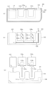
- FIG. 1 is an external perspective view of a change machine 1, which is an example of a paper sheet processing device.
- the change machine 1 is configured to be able to communicate with a POS control device 2 installed in a store. Specifically, the products purchased by the customer are registered in the POS control device 2. When all the products are registered, the total price of the products (hereinafter referred to as "purchase amount") is output from the POS control device 2 to the change machine 1.
- purchase amount is input, the change machine 1 accepts the customer's banknotes and coins.
- the total amount received from the customer hereinafter referred to as the "accepted amount" reaches the purchase amount, the change machine 1 transmits a notification to that effect to the POS control device 2.
- the change machine 1 includes a banknote processing unit 100 and a coin processing unit 200.
- the coin processing unit 200 is provided with a coin input port 201 and a coin discharge port 202.
- a customer's coin is inserted into the coin slot 201.
- the coin ejection port 202 can eject coins as change.
- the banknote processing unit 100 is provided with a banknote inlet/outlet 101.
- the banknote inlet/outlet 101 can take in customer's banknotes and can discharge banknotes as change.
- the banknote processing unit 100 is configured to include a housing 102.
- a storage unit 104 which will be described later, is housed inside the casing 102 (see FIG. 2(a)).
- Banknotes taken in from the banknote inlet/outlet 101 of the banknote processing unit 100 are stored in the storage unit 104 via the conveyance path 108 (see FIG. 2(b)) inside the casing 102. Moreover, the banknote processing unit 100 can discharge the banknotes stored in the storage unit 104 from the banknote inlet/outlet 101 as change. Although described in detail later, the storage unit 104 described above is configured to be removable from the banknote processing unit 100 (main unit 103) (see FIG. 2(c)).
- the change machine 1 is provided with a touch panel P and a mode changeover switch S.
- the touch panel P for example, the number of banknotes stored in the change machine 1 is displayed for each denomination.
- the mode changeover switch S is operated when changing the mode of the change machine 1.
- the change machine 1 shifts to operation mode, management mode, and maintenance mode.
- the operating mode is a mode in which bills and coins can be accepted from customers and change can be dispensed.
- the management mode is a mode in which banknotes stored in the change machine 1 can be managed.
- the maintenance mode is a mode in which the storage unit 104 can be removed from the change machine 1.
- the mode changeover switch S described above is composed of a cylinder lock having a keyhole into which a key can be inserted. For example, when the key inserted into the mode changeover switch S is rotated to the first position, the change machine 1 shifts to the operating mode. Similarly, when the key is rotated to the second position, the change machine 1 shifts to the management mode, and when the key is rotated to the third position, the change machine 1 shifts to the maintenance mode.
- the configuration for switching the mode of the change machine 1 is not limited to the above example. For example, a configuration may be adopted in which the mode of the change machine 1 can be changed when a preset password is input.
- FIG. 2(a) is a diagram for explaining the inside of the banknote processing unit 100 (casing 102) of the change machine 1.
- FIG. 2(a) is a cross section taken along the line AA of the banknote processing unit 100 in FIG.
- the housing 102 is equipped with a main unit 103, a storage unit 104 (x, y) that is detachably attached to the main unit, and a collection cassette 107.
- the storage unit 104 stores banknotes discharged as change.
- the storage unit 104 includes a storage unit 104x and a storage unit 104y.
- the denominations (A, B, C, D) of banknotes stored in the storage unit 104x and the storage unit 104y are different.
- the collection cassette 107 stores banknotes of denominations (E, F) that are not used as change among the banknotes taken in from the banknote inlet/outlet 101. That is, the collection cassette 107 stores banknotes of denominations that are not stored in the storage unit 104. Examples of banknotes of denominations that cannot be used as change include high-value banknotes.
- an upper limit number is set for the number of banknotes to be stored in the storage unit 104 for each denomination of the banknote. Assume that a banknote of a denomination that would originally be stored in the storage unit 104 is accepted, and the number of banknotes of the denomination in the storage unit 104 has reached the upper limit. In the above case, the banknotes are stored in the collection cassette 1077 instead of in the storage unit 104 (overflow).
- the storage unit 104 and collection cassette 107 are provided in the main unit 103.
- the storage unit 104 is removably disposed within the main unit 103.
- the storage unit 104 is configured to be portable when removed from the main unit 103.
- the collection cassette 107 is removably arranged within the main unit 103.
- the collection cassette 107 is configured to be portable when removed from the main unit 103.
- a removable lid portion 102a is provided at the upper opening of the housing 102.
- the main unit 103 is provided with a locking portion L1.
- the storage unit 104 can be removed from the main unit 103 by opening the lid 102a of the housing 102 and inserting a key into the lock L1 to unlock it.
- the collection cassette 107 is provided with a locking portion L2.
- the collection cassette 107 can be removed from the main unit 103 by opening the lid 102a of the housing 102 and inserting a key into the lock L2 to unlock it.
- the main unit 103 is provided with a banknote inlet/outlet 101 . Bills taken in from the bill inlet/outlet 101 are stored in the storage unit 104 or the collection cassette 107.
- FIG. 2(b) is a diagram for explaining a banknote transport path inside the banknote processing unit 100. Note that the casing 102 is omitted in FIG. 2(b).
- the storage unit 104 of this embodiment includes each drum 106.
- the banknote taken into the banknote inlet/outlet 101 is conveyed to a drum 106 (storage unit 104) according to the denomination of the banknote, and is wound up (stored) in the drum 106.
- the storage unit 104 is not limited to the above specific example and may be modified as appropriate.
- the banknote processing unit 100 of this embodiment can accept banknotes of various denominations including denomination A, denomination B, denomination C, denomination D, denomination E, and denomination F.
- the storage unit 104x of the storage units 104 includes a drum 106a and a drum 106b. Further, the storage unit 104y includes a drum 106c and a drum 106d.
- banknotes of denominations (A to D) used as change are stored in drums (a to d) according to the denomination of the banknotes.
- banknotes of denomination A are stored in the drum 106a
- banknotes of denomination B are stored in the drum 106b. That is, banknotes of denomination A and banknotes of denomination B are stored in the storage unit 104x.
- banknotes of denomination C are stored in the drum 106c
- banknotes of denomination D are stored in the drum 106d. That is, banknotes of denomination C and banknotes of denomination D are stored in the storage unit 104y.
- banknotes of denomination E and banknotes of denomination F which are not used as change, are stored in the collection cassette 107.
- the upper limit number of sheets is set for each drum 106 (denomination). When the number of banknotes stored in the drum 106 has reached the upper limit, even the banknotes of the denomination that would originally be stored in the drum 106 are stored in the collection cassette 107.
- the main unit 103 is provided with a conveyance path 108 through which banknotes are conveyed.
- the main unit 103 includes an identification unit for identifying the denomination of the banknote taken in from the banknote inlet/outlet 101, and changes the route along which the banknote is conveyed according to the identified denomination.
- the technology described in Japanese Patent No. 6505298, for example may be adopted as the technology for identifying the denomination of the banknote and the technology for changing the route along which the banknote is conveyed.
- a path is formed for conveying the banknote from the banknote inlet/outlet 101 to the drum 106a of the storage unit 104x. be done.
- a path is formed in which the banknote is conveyed from the banknote inlet/outlet 101 to the collection cassette 107.
- a banknote of denomination B, a banknote of denomination C, or a banknote of denomination D is taken in.
- the path is changed to a path in which the banknote is conveyed from the banknote inlet/outlet 101 to the collection cassette 107.
- the denomination F is taken in from the banknote inlet/outlet 101.
- a path is formed in which the banknotes are conveyed from the drum 106a to the banknote inlet/outlet 101.
- a banknote of denomination B, a banknote of denomination C, or a banknote of denomination D is discharged.
- the banknotes once stored in the collection cassette 107 cannot be ejected from the banknote inlet/outlet 101, but may be configured to be ejectable.
- FIG. 2(c) is a diagram for explaining the storage unit 104 (x, y) and the collection cassette 107 that have been removed from the main unit 103.
- the storage unit 104x is provided with a connector 105x
- the storage unit 104y is provided with a connector 105y.
- the main body unit 103 is provided with connectors 111x and 111y.
- the storage unit 104 (x, y) is provided with an individual memory 110 (x, y).
- the individual memory 110 described above stores identification information ID for identifying the storage unit 104 in which the individual memory 110 is provided.
- the main unit 103 includes a control unit 109. When the connector 105 of the storage unit 104 and the connector 111 of the main unit 103 are connected, the identification information ID stored in the individual memory 110 of the storage unit 104 becomes readable by the control unit 109 of the main unit 103.
- the control unit 109 determines whether an appropriate storage unit 104 has been attached based on the identification information ID.
- the change machine 1 monitors whether the connector 111 of the main unit 103 is connected to the connector 105 of the storage unit 104 and determines whether the storage unit 104 is attached to the main unit 103. In this embodiment, the time when the collection cassette 107 was attached and the time when it was removed are stored in the change machine 1 (main memory 115) as history information. Further, whether or not the collection cassette 107 is attached is detected by a sensor, and the time when the collection cassette 107 is attached and the time when it is removed are stored in the change machine 1 as history information.
- FIG. 3(a) and 3(b) are specific examples of the banknote processing method.
- the change machine 1 shifts to the operating mode, management mode, and operation mode.
- FIG. 3(a) is a specific example of a banknote processing method in the operating mode. For example, during the business period of the store, the change machine 1 is moved to the operating mode. In the operating mode, as described above, banknotes from customers are accepted and banknotes are discharged as change.
- banknotes (denominations A to D) to be used as change are accepted, the banknotes are stored in the storage unit 104 (drum 106) (Sa1 in FIG. 3(a)). Further, the banknotes in the storage unit 104 (drum 106) are discharged as change (Sa2 in FIG. 3(a)).
- the banknotes are stored in the collection cassette 107 (Sa3 in FIG. 3(a)). Even if the denomination to be used as change is accepted, if the upper limit number of banknotes of the denomination is stored in the storage unit 104, the banknote is stored in the collection cassette 107 (Sa4 in FIG. 3(a)). ). As described above, the banknotes stored in the collection cassette 107 are not discharged (recirculated).
- FIG. 3(b) is a diagram for explaining a specific example of a banknote processing method in maintenance mode.
- the collection cassette 107 can be removed as described above.
- the control unit 109 of the change machine 1 monitors whether the collection cassette 107 has been removed.
- the change machine 1 shifts to an error state when the collection cassette 107 is removed in a mode other than the maintenance mode.
- the time of transition to the above error state is stored in the main memory 115 as history information.
- the storage unit 104 is removed in a mode other than the maintenance mode, it shifts to an error state, and the time at which it shifts to the error state is stored in the main memory 115 as history information.
- the change machine 1 does not shift to an error state.
- the banknotes in the collection cassette 107 can be collected.
- an employee of a store shifts change machine 1 to maintenance mode after closing.
- the banknotes in the collection cassette 107 can be taken out and stored in the safe S (Sb1 in FIG. 3(b)).
- the safe S described above is installed, for example, in the backyard of a store.
- the banknotes in the collection cassette 107 may be stolen even during the store's business hours. Therefore, it may be appropriate to remove the banknotes from the collection cassette 107 and store them in the safe S during the store's business period.
- the store employee shifts the change machine 1 to maintenance mode in the middle of the business period and collects the banknotes in the collection cassette 107 (collects them midway).
- the change machine 1 stores the number of banknotes in the collection cassette 107 for each denomination as collection information N (see FIG. 5). Before collecting the banknotes in the collection cassette 107, it is necessary to shift the change machine 1 to the management mode and initialize the collection information N.
- the storage unit 104 can be carried while storing banknotes.
- the storage unit 104 removed from the main unit 103 can be stored in the safe S as it is without taking out the banknotes from the storage unit 104 (leaving them behind). Therefore, compared to, for example, a configuration in which all banknotes need to be taken out from the storage unit 104 at the time of closing, there is an advantage that the amount of work for employees at the store can be reduced. Furthermore, compared to, for example, a configuration in which banknotes are left in the change machine 1 when the store is closed, there is an advantage that the risk of banknotes used as change being stolen is suppressed.
- a store for example, a large store
- the plurality of storage units 104 removed from the plurality of change machines 1 are stored in the safe S.
- the number of bills stored in the storage unit 104 is usually different for each change machine 1. Further, the number of bills stored in the storage unit 104 is stored as storage information n on the main unit 103 side of the change machine 1 (see FIG. 5).
- the storage information n stored in the change machine 1 and the storage information n that the storage unit 104 actually stores An inconvenience may occur where the number of banknotes does not match. In this embodiment, the above-mentioned inconvenience is suppressed by storing the identification information ID in the storage unit 104.
- the above configuration will be described in detail later.
- FIG. 4 is a hardware configuration diagram of the change machine 1.
- the change machine 1 includes the storage unit 104 (x, y) and collection cassette 107 described above.
- the change machine 1 also includes a connector 111 (x, y) and a control unit 109.
- the connector 111 and control unit 109 described above are provided on the main unit 103 side of the change machine 1.
- the control unit 109 is configured to include a CPU (Central Processing Unit) 112, a ROM (Read Only Memory) 113, a RAM (Random Access Memory) 114, and a main memory 115.
- the ROM 113 stores various types of information in a non-volatile manner. For example, the ROM 113 stores various information including programs.
- CPU 112 executes a program stored in ROM 113.
- the RAM 114 can temporarily store various information. For example, the RAM 114 stores various information generated when the CPU 112 executes a program.
- the operation of taking in banknotes from the banknote inlet/outlet 101 is realized.
- Bills taken in from the bill inlet/outlet 101 are detected by various sensors, and detection signals are input to the control unit 109 .
- the control unit 109 determines the authenticity and denomination of the banknote based on the detection signal.
- the control unit 109 generates a drive signal for driving a motor and a solenoid according to the banknote determination result.
- banknotes are transported and stored in either the storage unit 104 (drums 106a to 106d) or the collection cassette 107 of the change machine 1. Note that if an appropriate determination result is not obtained, a reject operation is performed and the banknote is ejected from the banknote inlet/outlet 101.
- a flash memory is preferably employed as the main memory 304.
- a flash memory is illustrated as the main memory 304, other storage means may be employed as the main memory 304.
- an EEPROM may be used as the main memory 304.
- the main memory 115 described above stores various types of information.
- the main memory 115 stores storage information n(a to d) indicating the number of coins of each denomination stored in the storage unit 104 (see FIG. 5 described later).
- the main memory 115 also stores identification information ID for identifying the storage unit 104. The above identification information ID is given to each storage unit 104.
- each storage unit 104x removed from a different change machine 1 has different identification information ID (IDx).
- the storage units 104y removed from different change machines 1 have different identification information ID (IDy).
- IDx and IDy have different identification information IDs.
- the identification information ID is used when determining whether the storage unit 104 attached to the change machine 1 is appropriate.
- storage unit 104 includes drum 106 (a, b, c, d), connector 105 (x, y), and individual memory 110 (x, y).
- the storage unit 104x of the storage units 104 is provided with the drum 106a in which the denomination A is stored and the drum 106b in which the denomination B is stored, as described above.
- the storage unit 104y is provided with the drum 106c in which the denomination C is stored and the drum 106d in which the denomination D is stored, as described above.
- the connector 105 includes a connector 105x provided in the storage unit 104x of the storage unit 104 and a connector 105y provided in the storage unit 104y. As described above, when the storage unit 104x is attached to the change machine 1 (main unit 103), the connector 105x of the storage unit 104x is connected to the connector 111x of the main unit 103. Similarly, when the storage unit 104y is attached to the change machine 1, the connector 105y of the storage unit 104y is connected to the connector 111y of the main unit 103.
- the individual memory 110 includes an individual memory 110x provided in the storage unit 104x of the storage unit 104 and an individual memory 110y provided in the storage unit 104y.
- Information including identification information ID for identifying the storage unit 104 in which the individual memory 110 is provided is stored in each of the individual memories 110 (x, y) in a non-volatile manner. The above information of the individual memory 110 can be read by the control unit 109 while the connector 105 of the storage unit 104 in which the individual memory 110 is provided is connected to the connector 111 of the main unit 103.
- FIG. 5 is a diagram for explaining specific examples of each piece of information stored in the main memory 115 and the individual memories 110 (x, y).
- the main memory 115 main unit 103 side
- Each information in the main memory 115 is updated by the control unit 109.
- the first unit information Dx is various information regarding the storage unit 104x among the storage units 104(x, y). Specifically, the first unit information Dx includes identification information IDx of the storage unit 104x, storage information na indicating the number of banknotes (denomination A) stored in the drum 106a, and banknotes (denomination A) stored in the drum 106b. B) includes storage information nb indicating the number of banknotes, an upper limit number La of banknotes to be stored in the drum 106a, and an upper limit number Lb of banknotes to be stored in the drum 106b. In the specific example of FIG. 5, it is assumed that 19 banknotes of denomination A are stored in the drum 106a and 30 banknotes of denomination B are stored in the drum 106b.
- the second unit information Dy is various information regarding the storage unit 104y among the storage units 104(x, y).
- the second unit information Dy includes identification information IDy of the storage unit 104y, storage information nc indicating the number of banknotes (denomination C) stored in the drum 106c, and banknotes (denomination C) stored in the drum 106d.
- D) includes storage information nd indicating the number of banknotes, the upper limit number Lc of banknotes to be stored in the drum 106c, and the upper limit number Ld of banknotes to be stored in the drum 106d.
- FIG. 5 it is assumed that one banknote of denomination C is stored in the drum 106c and 17 banknotes of denomination D are stored in the drum 106d.
- storage information n corresponding to the drums 106 are added. For example, when one banknote (denomination A) is stored in the drum 106a, the storage information na of each storage information n is incremented by a numerical value "1". Further, when a banknote is discharged as change from the drum 106 of the change machine 1, the storage information n corresponding to the drum 106 is subtracted. For example, when one banknote (denomination A) is discharged from the drum 106a, the storage information na of each storage information n is subtracted by a numerical value "1".
- the upper limit number L(a-d) of banknotes to be stored in each drum 106(a-d) can be changed in the management mode. That is, in this embodiment, the upper limit number of banknotes to be left in the change machine 1 as change on the next day can be changed for each denomination. For example, the number of banknotes required as change may vary depending on the size of the store. Furthermore, in order to reduce the risk of theft, it is better not to leave more change than necessary in the change machine 1. By appropriately adjusting the upper limit number L of each drum 106, there is an advantage that the risk of theft can be reduced while keeping the necessary change.
- collection information N indicates the number of banknotes stored in the collection cassette 107.
- the collection information N includes collection information Na indicating the number of banknotes of denomination A stored in the collection cassette 107, collection information Nb indicating the number of banknotes of denomination B, and collection information Nb indicating the number of banknotes of denomination C stored in the collection cassette 107.
- collection information Nc indicating the number of banknotes of denomination D
- collection information Nd indicating the number of banknotes of denomination E
- collection information Ne representing the number of banknotes of denomination F
- collection information Nf indicating the number of banknotes of denomination F.
- the banknote is stored in the collection cassette 107, and a numerical value "1" is added to the collection information Ne of the collection information N.
- the banknotes are stored in the collection cassette 107.
- collection information N (a to d) indicating the number of banknotes of denominations (A to D) used as change is added. Note that, as described above, the banknotes in the collection cassette 107 are not discharged as change. Therefore, in principle, the collection information N is not subtracted. However, as will be described later, when the banknotes in the collection cassette 107 are collected, the collection information N (a to f) is initialized to a numerical value "0".
- the individual memory 110x of the storage unit 104x stores identification information IDx for identifying the storage unit 104x.
- the control unit 109 determines whether the identification information ID stored in the individual memory 110 of the storage unit 104 is appropriate. do.
- the identification information ID stored in the individual memory 110 of the storage unit 104 matches the identification information IDx stored in the main memory 115 of the control unit 109. It is automatically determined whether or not to do so. If the storage unit 104x removed from a device other than the original change machine 1 is attached to the connector 111x, the above-mentioned determination result will be inconsistent. Furthermore, if the storage unit 104y is connected to the connector 111x (rather than the connector 111y), the above-mentioned determination result will be inconsistent.
- the individual memory 110y of the storage unit 104y stores identification information IDy for identifying the storage unit 104y.
- the control unit 109 determines whether the identification information ID stored in the individual memory 110 of the storage unit 104 is appropriate. do.
- the identification information ID stored in the individual memory 110 of the storage unit 104 matches the identification information IDy stored in the main memory 115 of the control unit 109. It is automatically determined whether or not to do so. If the storage unit 104y removed from a change machine other than the original change machine is attached to the connector 111y, the above-mentioned determination result will be inconsistent. Furthermore, if the storage unit 104x is connected to the connector 111y (rather than the connector 111x), the above-mentioned determination result will be inconsistent.
- FIG. 6 is a functional block diagram of the banknote processing device 10.
- the change machine 1 functions as the banknote processing device 10 when the CPU 112 described above executes a program.
- the banknote processing apparatus 10 includes a main body 11, a storage section 12x, a storage section 12y, and a collection section 13.
- the storage unit 12 (x, y) is capable of storing banknotes accepted by the banknote processing device 10, and is also capable of discharging the stored banknotes.
- the storage section 12 of this embodiment includes a storage section 12x and a storage section 12y.
- the storage unit 104x described above functions as the storage section 12x
- the storage unit 104y functions as the storage section 12y.
- each storage unit 12 stores identification information ID for identifying the storage unit 12.
- the storage unit 12x stores banknotes of denomination A and banknotes of denomination B among banknotes accepted by the banknote processing device 10. Further, the storage section 12y stores banknotes of denomination C and banknotes of denomination D among the banknotes accepted by the banknote processing apparatus 10.
- the banknote processing apparatus 10 of this embodiment comprises two storage parts 12, the number of objects of the storage parts 12 can be changed suitably. For example, one storage section 12 may be provided, or three or more storage sections 12 may be provided.
- the collection unit 13 stores accepted banknotes during a period when the banknotes in the storage unit 12 reach the upper limit number L.
- the collection cassette 107 described above functions as the collection section 13. Further, when a banknote of denomination E or a banknote of denomination F that is not used as change is received by the banknote processing device 10, the banknote of the denomination is stored in the collection unit 13.
- the main body section 11 includes a storage section 12 (x, y) and a collection section 13 that are detachable.
- the main body unit 103 described above functions as the main body section 11.
- the main body section 11 is configured to include a storage section 14 and a control section 15, as shown in FIG.
- the main memory 115 described above functions as the storage unit 14.
- the above-mentioned CPU 112 functions as the control unit 15.
- the storage section 14 of the main body section 11 stores identification information ID that can identify the storage section 12 corresponding to the main body section 11 and storage information n (a ⁇ d).
- the storage unit 14 also stores collection information N indicating the number of banknotes stored in the collection unit 13 for each denomination (A to D), and banknotes of each denomination (A to D) stored in the storage unit 12.
- Each upper limit number of sheets L (a to d) is stored. In this embodiment, even if the power to the banknote processing device 10 is cut off during the period from when the store closes to when the store opens, each piece of information in the storage unit 14 is retained.
- the control section 15 of the main body section 11 includes a changing section 16, an initializing section 17, and a transition section 18.
- the changing unit 16 can change the upper limit number L of sheets stored in the storage unit 14. Specifically, the changing unit 16 can change the upper limit number L for each denomination.
- the upper limit number of sheets L is set to any value in the range "0 to 100".
- the numerical range that can be set as the upper limit number L can be changed as appropriate, for example, depending on the storage capacity of the storage section 12 (drum).
- the transition unit 18 transitions to a predetermined management mode. Specifically, the transition unit 18 transitions to one of the management mode, operation mode, and maintenance mode when the mode changeover switch S described above is operated appropriately.
- the initialization unit 17 can initialize collection information N (a to f) indicating the number of banknotes stored in the collection unit 13.
- the banknote processing device 10 includes a display section 19.
- the touch panel P described above functions as the display section 19.
- the display unit 19 displays various information.
- the display unit 19 displays the current value of the storage information n (see Go in FIG. 8, which will be described later).
- the display unit 19 also displays the current value of collection information N (see Gc in FIG. 8, which will be described later).
- the display unit 19 described above is configured to be able to accept touch operations. Each image displayed by the display unit 19 will be described later using FIG. 8.
- FIG. 7 is a diagram for explaining a specific example of leaving banknotes in the storage section 12x.
- banknotes of denomination A and banknotes of denomination B are stored in the storage section 12x.
- FIG. 7 a case will be described in which banknotes of denomination A and banknotes of denomination B are left in the storage section 12x.
- the storage section 12x is removed from the banknote processing device 10 and stored in the safe S at the time of closing.
- the storage part 12y is omitted.
- the banknotes in the storage section 12y can be processed in the same way as the banknotes in the storage section 12x.
- FIG. 7 it is assumed that the storage sections 12x are removed from the plurality of banknote processing devices 10 and stored in the safe S when the store is closed.
- a banknote processing apparatus 10v one of the plurality of banknote processing apparatuses 10
- a banknote processing apparatus 10w the other one will be referred to as a "banknote processing apparatus 10w”.
- the storage section 12x of the banknote processing device 10v is described as a “storage section 12xv”
- the storage section 12x of the banknote processing device 10w is described as a "storage section 12xw”.
- FIG. 7 shows a part of each information (na, nb, IDx) stored in the storage section 14v (main body section side) of each banknote processing apparatus 10v. Similarly, a portion of each information (na, nb, IDx) stored in the storage unit 14w of each banknote processing device 10w is shown.
- FIG. 7 shows the number of banknotes of denomination A and the number of banknotes of denomination B stored in the storage section 12x (v, w).
- n1 banknotes of denomination A and n2 banknotes of denomination B are stored in the storage section 12xv. That is, assume that n1 bills of denomination A and n2 bills of denomination B are stored in the bill processing device 10v at the time of store closing.
- the storage unit 12 of this embodiment stores identification information ID unique to the storage unit 12.
- the identification information ID of the storage section 12 to be attached to the banknote processing apparatus 10 is stored in the storage unit 14 (on the main body 11 side) of the banknote processing apparatus 10 .
- identification information IDxv is stored in the storage section 12xv that is removed from the banknote processing device 10v.
- identification information IDxv is stored in the storage unit 14v of the banknote processing device 10v.
- identification information IDxw is stored in the storage section 12xw removed from the banknote processing device 10w (IDxv ⁇ IDxw).
- identification information IDxw is stored in the storage unit 14w of the banknote processing device 10w.
- the banknote processing apparatus 10 of this embodiment automatically reads the identification information ID from the storage section 12 when the storage section 12 is attached. Further, the banknote processing device 10 determines whether the identification information ID stored in the storage section 14 and the identification information ID of the storage section 12 match. If the identification information ID of the storage section 12 and the identification information ID of the storage section 14 (main body section 11 side) match (for example, Sc1 in FIG. 7), the banknote processing apparatus 10 does not transition to the attachment error state.
- the banknote processing apparatus 10 shifts to an attachment error state.
- the installation error state for example, it is reported that an inappropriate storage section 12 is installed.
- a message indicating that an inappropriate storage section 12 is attached is displayed on the display section 19.
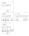
- FIG. 8 is a diagram for explaining each image (G Meeting, Gm, Gc, Gh) displayed on the display unit 19. As described above, the banknote processing device 10 shifts to the operation mode, management mode, and maintenance mode.
- FIG. 8 shows a simulation diagram of the operation mode image Go displayed in the operation mode, the management mode image Gm displayed in the management mode, the collection information image Gc, and the replenishing image Gh.
- the operation mode image Go displays the number of banknotes stored in the storage section 12 of the banknote processing device 10 for each denomination. That is, the operation mode image Go displays the number of remaining banknotes that can be discharged as change for each denomination.
- 19 banknotes of denomination A, 30 banknotes of denomination B, 1 banknote of denomination C, and 17 banknotes of denomination D are stored in the storage section 12.
- notification according to the remaining number of banknotes stored in the storage section 12 is executed in the operation mode image Go. For example, when the number of bills remaining in the storage section 12 is small, this fact is notified.
- the banknote processing device 10 stores storage information n(a to d) indicating the remaining number of banknotes of each denomination (A to D) in the storage unit 12.
- the banknote processing device 10 displays the remaining number of banknotes of the denomination corresponding to the storage information n in a special manner (orange color) during the period when the storage information n is in the range "0 to 5".
- the remaining number of banknotes of denomination C is 5 or less (1 sheet). That is, it is assumed that the storage information nc is the numerical value "5" or less.
- the remaining number of banknotes of denomination C is displayed in orange in the operation mode image Go.
- the storage section 12 is replenished with banknotes through a replenishment operation.
- the maximum number of banknotes that can be stored in the storage section 12 is predetermined for each denomination (for each drum 106), and when the number of banknotes stored in the storage section 12 approaches the maximum number, the operation mode image G0 is displayed as near full. Notification is executed. Specifically, when the storage information n indicating the number of banknotes stored in the storage unit 12 approaches the maximum number (for example, when "maximum number - n ⁇ 5"), the denomination corresponding to the storage information n is The number of banknotes is displayed in a special manner in the operation mode image Go. However, if an arbitrary upper limit number L is set, the above near-full notification will not be executed.
- the management mode image Gm is displayed instead of the operating mode image Go.
- the management mode image Gm displays the number of banknotes stored in the storage section 12, similarly to the operation mode image Go.
- the management mode image Gm also displays a replenishment button B1, a collection button B2, a payment button B3, and a cassette display button B4.
- the payment button B3 is operated when paying bills to a customer. Specifically, when the payment button B3 is touched, the number of bills to be discharged from the storage section 12 can be set for each denomination. Further, a set number of banknotes is discharged from the banknote processing device 10 (banknote inlet/outlet 101), and storage information n is subtracted according to the number of discharged banknotes.
- the collection information image Gc displays the number of banknotes stored in the collection unit 13 for each denomination.
- the banknote processing device 10 displays the number of banknotes of each denomination (A to F) stored in the collection unit 13 based on the collection information N (a to f) stored in the storage unit 14. .
- the total amount of money to be stored in the collection unit 13 is displayed in the collection information image Gc.
- the total amount to be stored in the collection unit 13 is calculated based on the collection information N.
- the collection unit 13 stores 3 banknotes of denomination A, 23 banknotes of denomination E, 30 banknotes of denomination F, and other denominations (B to D). Assume that banknotes are not stored. Note that, as described above, banknotes of denominations (A to D) used as change are stored in the storage section 12 in principle. However, if a new banknote of the denomination is received while the maximum number L of banknotes of the denominations (A to D) used as change is stored in the storage unit 12, the banknote will not be stored in the collection unit 13. (overflow). In the specific example of FIG. 8, it is assumed that three banknotes of denomination A overflow.
- the above collection information image Gc is displayed at an appropriate time. For example, when the store opens or closes, the collection information image Gc is displayed to confirm the number of banknotes stored in the collection section 13. If there are banknotes remaining in the collection unit 13 when the store opens or closes, the store employee collects the banknotes from the collection unit 13 and stores them in the safe. Further, during the business period of the store, the collection information image Gc is displayed to confirm the number of banknotes stored in the collection section 13. If a large amount of banknotes is stored in the collection unit 13 during the business period of the store, an employee of the store collects the banknotes in the collection unit 13 and stores them in a safe (recovers them in the middle).
- the replenishment button B1 of the management mode image Gm when touched, the replenishment image Gh is displayed.
- the storage unit 12 can be replenished with banknotes used as change. For example, when the store opens, if there are few banknotes in the storage section 12, the banknotes are replenished via the replenishment screen Gh.
- the operation mode image Go there are cases where a notification is made of the few remaining bills of each denomination in the storage section 12. In the above case, the storage unit 12 is replenished with banknotes during the store's business period.
- An end button B5, a start button B6, and a stop button B7 are displayed on the supplementary image Gh.
- the start button B6 is touched, the taking in of banknotes from the banknote inlet/outlet 101 is started. Specifically, the banknote inlet/outlet 101 is formed such that the leading end of a banknote bundle can be inserted thereinto.
- the start button B6 is touched with the tip of the banknote bundle inserted into the banknote inlet/outlet 101, the banknotes of the banknote bundle are taken into the banknote processing device 10 one by one.
- the stop button B7 is touched, the capture operation is stopped.
- the number of bills replenished for each denomination is displayed in the replenishment image Gh.
- the replenishment image Gh displays the total amount of replenishment.
- the management mode image Gm is displayed instead of the supplementary image Gh.
- the upper limit number L of banknotes to be stored in the storage section 12 is set for each denomination. If a banknote is taken in by a touch operation on the replenishment image Gh (B6), and the storage information n of the denomination of the banknote reaches the upper limit number L, the banknote is ejected from the banknote inlet/outlet 101. be done.
- FIG. 9 is a diagram for explaining each image displayed when banknotes are collected from the banknote processing apparatus 10.
- FIG. 9 shows a simulation diagram of the selected image Gs, a simulation diagram of the collection image Ga, and a simulation diagram of the denomination designation image Gd.
- the selection image Gs in FIG. 9 is displayed when the collection button B2 of the management mode image Gm is touched.
- the selection image Gs is an image for enabling selection of banknotes to be collected from the banknote processing device 10 (storage section 12, collection section 13).
- the selection image Gs displays an end button B5, a cassette collection button B8, a denomination designation button B9, a number designation button B10, and an all collection button B11.
- the cassette collection button B8 is touch-operated when collecting banknotes currently stored in the collection unit 13.
- the collection image Ga in FIG. 9 is displayed when the cassette collection button B8 of the selected image Gs is touched.
- the collected image Ga displays an end button B5 and an initialize button B12.
- the collection information N is initialized.
- the collection information N includes collection information Na indicating the number of banknotes of denomination A stored in the collection unit 13, collection information Nb indicating the number of banknotes of denomination B, and number of banknotes of denomination C.
- collection information Nc indicating the number of banknotes of denomination D
- collection information Nd representing the number of banknotes of denomination D
- collection information Ne representing the number of banknotes of denomination E
- collection information Nf representing the number of banknotes of denomination F.
- the collection information N When the collection information N is initialized, it is necessary to take out the banknotes from the collection unit 13 before shifting to the operation mode. If the banknotes in the collection unit 13 are not taken out after initializing the collection information N, the number of banknotes indicated by the collection information N and the number of banknotes actually stored in the collection unit 13 will no longer match. For example, after initializing the collection information N, a store employee shifts to maintenance mode, removes the collection unit 13, and takes out banknotes.
- the denomination designation button B9 when the denomination designation button B9 is touched, a denomination designation image Gd is displayed.
- the denomination designation button B9 of the selection image Gs is touch-operated when collecting some (or all) of the banknotes in the storage unit 12 in addition to the banknotes currently stored in the collection unit 13.
- the denomination designation image Gd includes a denomination button B13 corresponding to denomination A, a denomination button B14 corresponding to denomination B, a denomination button B15 corresponding to denomination C, and a denomination button B15 corresponding to denomination C.
- a corresponding denomination button B16 and start button B17 are displayed.
- the banknote processing device 10 initializes storage information n(a to d) indicating the number of banknotes conveyed from the storage unit 12 to the collection unit 13 to a numerical value “0”. Further, the collection information N is updated according to the banknotes stored in the collection unit 13. After transporting the banknotes in the storage unit 12 to the collection unit 13 using the denomination designation button B9 (start button 17), the store employee initializes the storage information N using the collection image Ga described above, and then Collect banknotes. In this embodiment, if the start button B17 is touched after selecting a plurality of denomination buttons B, banknotes of a plurality of denominations can be collected into the collection unit 13 at once.
- the number of bills designation button B10 is operated when collecting a designated number of bills from the storage section 12. Specifically, when the number of coins designation button B10 is operated, a number of coins designation image that allows the number of coins to be designated for each denomination is displayed.
- the number-of-bills designation image is a screen on which the number of bills to be collected can be entered for each denomination.
- the designated number of banknotes is discharged from the banknote inlet/outlet 101.
- storage information n in the storage unit 14 is updated according to the discharged banknotes. According to the above number-of-bills designation image, the banknotes in the storage section 12 can be collected without removing the collection section 13. However, a configuration may be adopted in which the number of banknotes specified by the number-of-sheets designation image is conveyed to the collection unit 13.
- the all collection button B11 is operated when collecting all banknotes from the banknote processing device 10. Specifically, when the all collection button B11 is operated, all banknotes stored in the storage section 12 are transported to the collection section 13. After transporting all banknotes to the collection unit 13, the store employee initializes the storage information N using the collection image Ga described above, and then collects the banknotes in the collection unit 13.
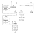
- FIG. 10(a) is a flowchart of the banknote storage process of the banknote processing device 10.
- the banknote processing device 10 executes a banknote storage process when storing banknotes in the storage section 12 or the collection section 13 . Specifically, when a banknote is inserted into the banknote inlet/outlet 101, the banknote storage process is executed.
- the technique described in Japanese Patent No. 6505298 for example, may be adopted as the technique for conveying the banknotes from the banknote inlet/outlet 101 to the storage section 12 or the collection section 13.
- the banknote processing device 10 When a banknote is taken in from the banknote inlet/outlet 101, the banknote processing device 10 identifies the denomination of the banknote (S100). Specifically, the denomination of the banknote is identified based on the detection signal from the sensor provided on the above-mentioned conveyance path 108 (see FIG. 2(b)). Thereafter, the banknote processing device 10 determines whether the denomination of the accepted banknote is one of denominations A to D (S101). That is, the banknote processing device 10 determines whether or not the received banknote is a banknote to be used as change.
- the banknote processing device 10 When determining that the banknote is not a banknote to be used as change (it is a banknote of denomination E or F) (S101: No), the banknote processing device 10 conveys the banknote to the collection unit 13 and stores it (S102). Moreover, the banknote processing device 10 updates (adds) the collection information N according to the denomination of the banknotes stored in the collection unit 13 (S103). For example, when a banknote of denomination E is stored in the collection unit 13, a numerical value "1" is added to the collection information Ne of the collection information N. In this embodiment, the collection information N is updated after the operation of storing banknotes in the collection unit 13 is completed.
- the banknote processing device 10 stores the storage information n (a to d) corresponding to the denomination in the upper limit number L. It is determined whether or not it is greater than or equal to (a to d) (S104). That is, it is determined whether or not the maximum number L of newly taken banknotes of the denomination is already stored in the storage unit 12 . For example, when a banknote of denomination A is taken in, the banknote processing device 10 determines whether storage information na indicating the number of banknotes of denomination A stored in the storage section 12 has reached the upper limit number La. judge.
- the banknote processing device 10 stores the banknote in the storage unit 12 (S105). Specifically, banknotes of denomination A and banknotes of denomination B are stored in the storage section 12x, and banknotes of denomination C and banknotes of denomination D are stored in the storage section 12y.
- the banknote processing device 10 updates the storage information n corresponding to the denomination of the banknote (adds a numerical value of "1") (S106), and ends the banknote storage process.
- the banknote processing device 10 stores the banknote in the collection unit 13. Moreover, the collection information N is updated according to the denomination of the banknote. After updating the collection information N, the banknote processing device 10 ends the banknote storage process. For example, when banknotes of denomination A are stored in the collection unit 13 (when banknotes of denomination A overflow), a value of "1" is added to the collection information Na.
- FIG. 10(b) is a flowchart of the installation process executed by the banknote processing device 10.
- the attachment process is executed to determine whether or not an appropriate storage section 12 has been attached to the banknote processing device 10 (main body section 11).
- the banknote processing apparatus 10 determines whether or not the power has just been turned on (S110). Specifically, the banknote processing device 10 executes the attachment process at predetermined intervals during the period when power is supplied. In step S110, it is determined whether this is the first installation process after the power is turned on.
- the banknote processing device 10 executes the processes from step S112 onwards, and determines whether the appropriate storage section 12 has been attached. According to the above configuration, even if the storage section 12 is attached to the banknote processing apparatus 10 during a period when the power supply is cut off, there is an advantage that the suitability of the storage section 12 can be determined.
- the banknote processing device 10 determines whether the storage section 12 has been newly attached to the main body section 11 (S111). Specifically, when the storage section 12 is attached to the main body 11 of the banknote processing device 10, the connector (110) of the storage section 12 is connected to the connector (111) of the main body 11. The banknote processing device 10 monitors whether each connector is connected. When each connector changes from an unconnected state to a connected state, it is determined that the storage section 12 is newly attached.
- step S111 If it is determined that the storage section 12 is not newly attached (S111: No), the bill processing device 10 ends the attachment process. If the determination in step S111 is "No", the storage section 12 is removed from the main body 11, or the storage section 12 continues to be attached to the main body 11. It is assumed that the
- the banknote processing device 10 reads the identification information ID (x, y) from the storage section 12. Moreover, the banknote processing device 10 compares the identification information ID read from the storage section 12 and the identification information ID stored in the storage section 14 (S113).
- attachment position x the position in the banknote processing apparatus 10 at which the storage section 12x that stores banknotes of denomination A and banknotes of denomination B is attached.
- attachment position y the position in the banknote processing apparatus 10 at which the storage section 12y that stores banknotes of denomination C and banknotes of denomination D is attached.
- the banknote processing device 10 After comparing the identification information ID read from the storage unit 12 and the identification information ID in the storage unit 14, the banknote processing device 10 determines whether the respective identification information IDs match (S114). If it is determined that the respective identification information IDs match (S114: Yes), the banknote processing device 10 ends the attachment process. On the other hand, if it is determined that the respective identification information IDs do not match (S114: No), the banknote processing device 10 shifts to an attachment error state (S115). In the attachment error state, for example, it is reported that the appropriate storage section 12 is not attached.
- the upper limit number L can be set for each denomination, but the above structure can be changed as appropriate.
- a configuration may be adopted in which a common upper limit number L is set for each denomination.
- a configuration may be adopted in which the range of numerical values that can be set as the upper limit number L changes for each denomination. For example, among the banknotes of each denomination stored as change, the higher the denomination, the smaller the numerical value that can be set as the upper limit number L.
- Control in each type of error state can be set as appropriate.
- the identification information ID of the incorrectly installed storage section 12 may be stored in the storage section 14 as history information. Further, in the installation error state, the identification information ID of the incorrectly installed storage section 12 may be displayed on the display section 19.
- it may be configured to be able to shift to the operating mode in the installation error state.
- it may be configured such that it is possible to take in customer's banknotes and also to be able to discharge change.
- a notification is given that the number of banknotes in the storage section 12 and the collection section 13 is unknown.
- a configuration may be adopted in which it is impossible to take in and eject banknotes in the attachment error state.
- the trigger for canceling the installation error state can be changed as appropriate.
- a configuration may be adopted in which the attachment error state is canceled when an appropriate storage section 12 is attached to the banknote processing device 10.
- the above-described installation process (see FIG. 10(b)) is executed even in the installation error state. If it is determined that the identification information ID of the newly attached storage unit 12 and the identification information ID stored in the banknote processing device 10 (storage unit 14) match, the installation error state may be canceled.
- the error state may be canceled.
- the above reset process can be executed, for example, when a predetermined reset switch is operated.
- a configuration may be adopted in which the reset process is executed when power supply is started.
- the attachment error state can be canceled by turning off the power once and then turning on the power.
- the banknotes in the storage unit 12 are collected into the collection unit 13.
- the start button B17 of the denomination designation image Gd is operated and when the all collection button B11 (see FIG. 9) is operated, the banknotes in the storage section 12 are collected into the collection section 13.
- the banknotes stored in the storage section 12 cannot be taken out except for the above collection operation.
- a configuration may also be adopted in which a locking device is provided in the storage section 12 and banknotes can be taken out from inside the storage section 12 when the locking device is unlocked.
- the history of the removal of the storage section 12 from the main body 11 time, mode
- the history of the removal of the collection section 13 the history of the storage of banknotes in the storage section 12
- history of bills being discharged from the storage section 12 denoted from the collection section 13
- history of bills being stored in the collection section 13 history of bills being discharged from the collection section 13, and storage section
- a preferred configuration is such that the history (denomination, time, mode) of the conveyance of banknotes from 12 to collection section 13 is recorded in storage section 14 and can be displayed on display section 19 .
- bills can be ejected when the payment button B3 is operated and when the start button B17 is operated.
- the history may be stored so as to be able to distinguish whether the bill was discharged by operating the payment button B3 or by operating the start button B17.
- the configuration for changing the upper limit number L may be changed as appropriate.
- the upper limit number L may be configured to be changeable while the banknotes are stored in the storage unit 12.
- the changed upper limit number L desired by the user may be smaller than the number of banknotes stored in the storage section 12.
- a configuration may be adopted in which the upper limit number L cannot be changed while the banknotes are stored in the storage section 12.
- a configuration can be considered in which the upper limit number L can be changed after all banknotes in the storage section 12 are transferred to the collection section 13 using the above-mentioned all collection button B11 (see FIG. 9).
- the upper limit number L may be changed to a value smaller than the number of banknotes stored in the storage section 12.
- a configuration may be adopted in which the upper limit number L of sheets can be set smaller than the current value of the storage information n.
- a configuration is preferable in which notification that more banknotes than the upper limit number L are stored in the storage unit 12 (hereinafter referred to as "over notification") is executed during a period when the upper limit number L is smaller than the storage information n. It is.
- over-notification may be performed on a dedicated lamp or may be performed on the display unit 19.
- a configuration may be adopted in which the transition to the operation mode is not possible during the period in which over-notification is performed.
- the control mode is shifted to the management mode, and the banknotes in the storage unit 12 are discharged from the banknote inlet/outlet 101 or conveyed to the storage unit 12.
- the management mode when the number of banknotes in the storage section 12 is adjusted and the storage information n decreases below the updated upper limit number L, the over-notification is stopped and it becomes possible to shift to the operation mode.
- a change machine (banknote processing device) is illustrated as an example of a paper sheet processing device.
- the present invention may be adopted in applications other than change machines.
- the paper sheet processing device is not limited to banknotes, and may be a device that handles various paper sheets such as securities, tickets, voting papers, envelopes, and others.
- the present invention is, for example, the following paper sheet processing apparatus, paper sheet processing method, and program.
- a paper sheet processing device is a paper sheet processing device (10) capable of receiving paper sheets, which is capable of storing received paper sheets and capable of discharging the stored paper sheets. (12x, 12y), and a main body (11) that is removably equipped with a storage section, and the main body has identification information (IDx, IDy) that can identify the storage section corresponding to the main body. It also includes a storage unit (14) that stores storage information (na to nd) that can specify the number of sheets stored in the storage unit.
- the storage section (14) stores the upper limit number of paper sheets (La to Ld) to be stored in the storage section, and the storage section (14) stores the upper limit number of paper sheets (La to Ld) to be stored in the storage section, and stores the number of sheets that are accepted during the period when the number of paper sheets in the storage section reaches the upper limit number. It is also possible to adopt an embodiment including a collecting section (13) that stores leaves and a changing section (16) that can change the upper limit number of leaves.
- the main body section is detachably equipped with a collection section, and the storage section stores collection information (Na to Nd) that can specify the number of paper sheets stored in the collection section, and stores collection information (Na to Nd) that can specify the number of paper sheets stored in the collection section.
- collection information Na to Nd
- collection information Na to Nd
- an embodiment including a transition section (18) that shifts to the management mode by operation, and an initialization section (17) that can initialize collection information among storage information and collection information in the management mode.
- a preferred aspect of the present invention includes a storage section that can receive paper sheets, store the received paper sheets, and eject the stored paper sheets; and a main body section that is detachably equipped with the storage section.
- a paper sheet processing method using a paper sheet processing device comprising: a step of storing storage information (S106) that can specify the amount of money stored in the storage section; This paper sheet processing method includes a step (S114) of determining the suitability of the stored storage section.
- a preferred embodiment of the present invention is a program that causes a computer to execute each step of the above embodiments.
Landscapes
- Physics & Mathematics (AREA)
- General Physics & Mathematics (AREA)
- Pile Receivers (AREA)
- Cash Registers Or Receiving Machines (AREA)
- Financial Or Insurance-Related Operations Such As Payment And Settlement (AREA)
Priority Applications (3)
| Application Number | Priority Date | Filing Date | Title |
|---|---|---|---|
| EP23865021.2A EP4589558A1 (en) | 2022-09-14 | 2023-06-23 | Paper sheet processing device, and paper sheet processing method |
| AU2023340956A AU2023340956B2 (en) | 2022-09-14 | 2023-06-23 | Paper sheet processing device, and paper sheet processing method |
| MX2025002645A MX2025002645A (es) | 2022-09-14 | 2025-03-05 | Dispositivo de procesamiento de una hoja de papel y metodo de procesamiento de una hoja de papel |
Applications Claiming Priority (2)
| Application Number | Priority Date | Filing Date | Title |
|---|---|---|---|
| JP2022146062A JP7680405B2 (ja) | 2022-09-14 | 2022-09-14 | 紙葉処理装置、及び紙葉処理方法 |
| JP2022-146062 | 2022-09-14 |
Publications (1)
| Publication Number | Publication Date |
|---|---|
| WO2024057658A1 true WO2024057658A1 (ja) | 2024-03-21 |
Family
ID=90274525
Family Applications (1)
| Application Number | Title | Priority Date | Filing Date |
|---|---|---|---|
| PCT/JP2023/023434 Ceased WO2024057658A1 (ja) | 2022-09-14 | 2023-06-23 | 紙葉処理装置、及び紙葉処理方法 |
Country Status (5)
| Country | Link |
|---|---|
| EP (1) | EP4589558A1 (https=) |
| JP (1) | JP7680405B2 (https=) |
| AU (1) | AU2023340956B2 (https=) |
| MX (1) | MX2025002645A (https=) |
| WO (1) | WO2024057658A1 (https=) |
Families Citing this family (1)
| Publication number | Priority date | Publication date | Assignee | Title |
|---|---|---|---|---|
| JP2025141406A (ja) | 2024-03-15 | 2025-09-29 | セイコーエプソン株式会社 | プリントヘッド、及び液体吐出装置 |
Citations (3)
| Publication number | Priority date | Publication date | Assignee | Title |
|---|---|---|---|---|
| JP2008210104A (ja) | 2007-02-26 | 2008-09-11 | Toshiba Tec Corp | Posシステム |
| WO2012114449A1 (ja) * | 2011-02-22 | 2012-08-30 | グローリー株式会社 | 現金処理システム、現金精算装置、現金出納装置、および、現金処理方法 |
| JP6505298B1 (ja) | 2018-06-28 | 2019-04-24 | 日本金銭機械株式会社 | 紙葉処理装置 |
-
2022
- 2022-09-14 JP JP2022146062A patent/JP7680405B2/ja active Active
-
2023
- 2023-06-23 AU AU2023340956A patent/AU2023340956B2/en active Active
- 2023-06-23 EP EP23865021.2A patent/EP4589558A1/en active Pending
- 2023-06-23 WO PCT/JP2023/023434 patent/WO2024057658A1/ja not_active Ceased
-
2025
- 2025-03-05 MX MX2025002645A patent/MX2025002645A/es unknown
Patent Citations (3)
| Publication number | Priority date | Publication date | Assignee | Title |
|---|---|---|---|---|
| JP2008210104A (ja) | 2007-02-26 | 2008-09-11 | Toshiba Tec Corp | Posシステム |
| WO2012114449A1 (ja) * | 2011-02-22 | 2012-08-30 | グローリー株式会社 | 現金処理システム、現金精算装置、現金出納装置、および、現金処理方法 |
| JP6505298B1 (ja) | 2018-06-28 | 2019-04-24 | 日本金銭機械株式会社 | 紙葉処理装置 |
Also Published As
| Publication number | Publication date |
|---|---|
| AU2023340956A1 (en) | 2025-02-27 |
| JP7680405B2 (ja) | 2025-05-20 |
| EP4589558A1 (en) | 2025-07-23 |
| MX2025002645A (es) | 2025-04-02 |
| AU2023340956B2 (en) | 2026-04-23 |
| JP2024041319A (ja) | 2024-03-27 |
Similar Documents
| Publication | Publication Date | Title |
|---|---|---|
| JP3902402B2 (ja) | 現金自動取引装置 | |
| KR101216564B1 (ko) | 현금처리기 | |
| JP2015156141A (ja) | 金銭処理装置および金銭処理装置の在高管理方法 | |
| JP3443676B2 (ja) | 貨幣入出金装置 | |
| JP4626273B2 (ja) | 現金処理装置 | |
| WO2024057658A1 (ja) | 紙葉処理装置、及び紙葉処理方法 | |
| JP6291905B2 (ja) | 金銭処理装置 | |
| CN105378807B (zh) | 纸币处理装置和纸币处理方法 | |
| JP4894322B2 (ja) | 現金処理装置 | |
| JP5219470B2 (ja) | 取引処理装置 | |
| JPH10334315A (ja) | 自動取引装置 | |
| JP4475884B2 (ja) | 自動取引装置 | |
| JP5194413B2 (ja) | 現金入出金機 | |
| JP2000276632A (ja) | 貨幣入金機 | |
| JP6761326B2 (ja) | 貨幣処理機および貨幣処理方法 | |
| JP6417789B2 (ja) | 紙葉類入出金装置及び紙葉類入出金方法 | |
| JP5293277B2 (ja) | 現金処理装置 | |
| JP7495314B2 (ja) | 紙幣入出金装置およびプログラム | |
| JP2018084948A (ja) | 現金処理装置 | |
| JP6587312B2 (ja) | 有価媒体処理装置、有価媒体処理システムおよび有価媒体処理方法 | |
| JP2017151928A (ja) | 自動取引装置 | |
| WO2014141388A1 (ja) | 貨幣入出金装置及び貨幣処理方法 | |
| JPH07168967A (ja) | 現金入出金装置 | |
| JP2010211252A (ja) | 現金管理装置 | |
| JP2008077195A (ja) | 現金処理装置 |
Legal Events
| Date | Code | Title | Description |
|---|---|---|---|
| 121 | Ep: the epo has been informed by wipo that ep was designated in this application |
Ref document number: 23865021 Country of ref document: EP Kind code of ref document: A1 |
|
| WWE | Wipo information: entry into national phase |
Ref document number: AU2023340956 Country of ref document: AU |
|
| ENP | Entry into the national phase |
Ref document number: 2023340956 Country of ref document: AU Date of ref document: 20230623 Kind code of ref document: A |
|
| WWE | Wipo information: entry into national phase |
Ref document number: 2501001552 Country of ref document: TH |
|
| REG | Reference to national code |
Ref country code: BR Ref legal event code: B01A Ref document number: 112025004580 Country of ref document: BR |
|
| WWE | Wipo information: entry into national phase |
Ref document number: 2023865021 Country of ref document: EP |
|
| NENP | Non-entry into the national phase |
Ref country code: DE |
|
| ENP | Entry into the national phase |
Ref document number: 2023865021 Country of ref document: EP Effective date: 20250414 |
|
| WWP | Wipo information: published in national office |
Ref document number: 2023865021 Country of ref document: EP |
|
| ENP | Entry into the national phase |
Ref document number: 112025004580 Country of ref document: BR Kind code of ref document: A2 Effective date: 20250311 |