WO2024057513A1 - 物理量検出装置 - Google Patents
物理量検出装置 Download PDFInfo
- Publication number
- WO2024057513A1 WO2024057513A1 PCT/JP2022/034691 JP2022034691W WO2024057513A1 WO 2024057513 A1 WO2024057513 A1 WO 2024057513A1 JP 2022034691 W JP2022034691 W JP 2022034691W WO 2024057513 A1 WO2024057513 A1 WO 2024057513A1
- Authority
- WO
- WIPO (PCT)
- Prior art keywords
- peak value
- strain
- tire
- time
- physical quantity
- Prior art date
- Legal status (The legal status is an assumption and is not a legal conclusion. Google has not performed a legal analysis and makes no representation as to the accuracy of the status listed.)
- Ceased
Links
Images





Classifications
-
- B—PERFORMING OPERATIONS; TRANSPORTING
- B60—VEHICLES IN GENERAL
- B60C—VEHICLE TYRES; TYRE INFLATION; TYRE CHANGING; CONNECTING VALVES TO INFLATABLE ELASTIC BODIES IN GENERAL; DEVICES OR ARRANGEMENTS RELATED TO TYRES
- B60C23/00—Devices for measuring, signalling, controlling, or distributing tyre pressure or temperature, specially adapted for mounting on vehicles; Arrangement of tyre inflating devices on vehicles, e.g. of pumps or of tanks; Tyre cooling arrangements
- B60C23/06—Signalling devices actuated by deformation of the tyre, e.g. tyre mounted deformation sensors or indirect determination of tyre deformation based on wheel speed, wheel-centre to ground distance or inclination of wheel axle
- B60C23/064—Signalling devices actuated by deformation of the tyre, e.g. tyre mounted deformation sensors or indirect determination of tyre deformation based on wheel speed, wheel-centre to ground distance or inclination of wheel axle comprising tyre mounted deformation sensors, e.g. to determine road contact area
-
- B—PERFORMING OPERATIONS; TRANSPORTING
- B60—VEHICLES IN GENERAL
- B60W—CONJOINT CONTROL OF VEHICLE SUB-UNITS OF DIFFERENT TYPE OR DIFFERENT FUNCTION; CONTROL SYSTEMS SPECIALLY ADAPTED FOR HYBRID VEHICLES; ROAD VEHICLE DRIVE CONTROL SYSTEMS FOR PURPOSES NOT RELATED TO THE CONTROL OF A PARTICULAR SUB-UNIT
- B60W40/00—Estimation or calculation of non-directly measurable driving parameters for road vehicle drive control systems not related to the control of a particular sub unit, e.g. by using mathematical models
- B60W40/12—Estimation or calculation of non-directly measurable driving parameters for road vehicle drive control systems not related to the control of a particular sub unit, e.g. by using mathematical models related to parameters of the vehicle itself, e.g. tyre models
-
- G—PHYSICS
- G01—MEASURING; TESTING
- G01L—MEASURING FORCE, STRESS, TORQUE, WORK, MECHANICAL POWER, MECHANICAL EFFICIENCY, OR FLUID PRESSURE
- G01L1/00—Measuring force or stress, in general
- G01L1/20—Measuring force or stress, in general by measuring variations in ohmic resistance of solid materials or of electrically-conductive fluids; by making use of electrokinetic cells, i.e. liquid-containing cells wherein an electrical potential is produced or varied upon the application of stress
- G01L1/22—Measuring force or stress, in general by measuring variations in ohmic resistance of solid materials or of electrically-conductive fluids; by making use of electrokinetic cells, i.e. liquid-containing cells wherein an electrical potential is produced or varied upon the application of stress using resistance strain gauges
- G01L1/2287—Measuring force or stress, in general by measuring variations in ohmic resistance of solid materials or of electrically-conductive fluids; by making use of electrokinetic cells, i.e. liquid-containing cells wherein an electrical potential is produced or varied upon the application of stress using resistance strain gauges constructional details of the strain gauges
- G01L1/2293—Measuring force or stress, in general by measuring variations in ohmic resistance of solid materials or of electrically-conductive fluids; by making use of electrokinetic cells, i.e. liquid-containing cells wherein an electrical potential is produced or varied upon the application of stress using resistance strain gauges constructional details of the strain gauges of the semi-conductor type
-
- G—PHYSICS
- G01—MEASURING; TESTING
- G01M—TESTING STATIC OR DYNAMIC BALANCE OF MACHINES OR STRUCTURES; TESTING OF STRUCTURES OR APPARATUS, NOT OTHERWISE PROVIDED FOR
- G01M17/00—Testing of vehicles
- G01M17/007—Wheeled or endless-tracked vehicles
- G01M17/02—Tyres
Definitions
- the present invention relates to a physical quantity detection device that detects a physical quantity of a tire condition.
- a device that detects a physical quantity related to the condition of the tire (physical quantity detection device) is attached to the tire, data is exchanged with a vehicle control device installed in the vehicle by wireless communication. Since the tires are rotatably supported by the vehicle, it is difficult to supply power from the vehicle to the physical quantity detection device. Therefore, it is necessary to provide a power source within the physical quantity detection device, and for example, a coin battery or the like may be used as the power source within the physical quantity detection device. In other words, it was necessary to drive the physical quantity detection device based on a limited power source such as a coin battery.
- Patent Document 1 discloses a technology that transmits only information on the grounding side region or only information on the non-grounding side region to the vehicle side, and transmits necessary tire information to the vehicle side with low current consumption. There is.
- Patent Document 1 two peak positions of the sensor measurement values that are the stepping point and the kicking point are calculated, the interval between these two peak positions is defined as the contact side area of the tire, and this contact side area is used as the transmission section by the sensor.
- the acquired tire information is sent to the vehicle. Therefore, the sensor must be supplied with current from the power source at least during the time from when the sensor-arranged portion of the tire touches the road surface until it separates from the road surface, which increases current consumption. In other words, since current consumption increases even in locations where information is not needed, there is a risk that the effect of reducing current consumption may not be fully demonstrated.
- An object of the present invention is to eliminate the need for the sensor mounted on the tire to separate from the road surface and the ground, and to control the energization method even during the ground contact period when the sensor placement part of the tire is in contact with the road surface.
- An object of the present invention is to provide a physical quantity detection device that reduces current consumption.
- the physical quantity detection device of the present invention includes: A physical quantity detection device installed in a tire to detect a physical quantity of the state of the tire, the device comprising: a strain detection section that detects strain in the tire; a signal processing unit that processes the detection signal detected by the strain detection unit,
- the signal processing section includes: A peak value of strain occurring on either compression or tension side when the tire is rotated so that the strain detection area of the tire contacts the road surface, and a strain detection area of the tire that is lower than the road surface from the time of depression Extracting the intermediate point peak value of strain occurring on either the compression or tension side at an intermediate point up to the time of kicking off, From the time difference from the depression peak value to the intermediate point peak value or the slope of the change in strain, calculate the period in which the depression peak value and the intermediate point peak value occur from the next time onward, and calculate the period in which the depression peak value and the intermediate point peak value occur from next time
- the feature is that the strain detection section is energized.
- the present invention it is possible to make the time for energizing the strain sensor shorter than the time required from the time when the tire's strain detection area contacts the road surface due to rotation of the tire until the time when the tire is kicked off from the road surface. It is possible to provide a physical quantity detection device that can reduce current consumption during the grounding period until the power is removed.
- FIG. 1 is a block diagram showing a schematic configuration of a vehicle equipped with a strain sensor according to the present embodiment.
- FIG. 2 is a schematic diagram showing a state in which a tire having a strain sensor rolls on a road surface as the vehicle moves.
- FIG. 3 is an explanatory diagram showing a sensor signal waveform of a strain sensor according to a rotational state of a tire.
- FIG. 1 is a diagram illustrating the hardware configuration of a physical quantity detection device according to the present embodiment.
- FIG. 2 is a functional block diagram showing the configuration of a signal processing section of the physical quantity detection device according to the present embodiment. An example of a flowchart showing the processing of the signal processing unit according to the present embodiment.
- FIG. 4 is a graph showing an example of waveform data measured by the physical quantity detection device according to the present embodiment and whether or not electricity is applied at that time.
- FIG. 3 is a schematic diagram illustrating an example of correcting means for correcting the energization time width at the peak of depression, which is processed by the physical quantity detection device according to the present embodiment.
- FIG. 3 is a diagram showing a measured waveform of a strain value including irregular values of the physical quantity detection device according to the present embodiment.
- 5 is a timing chart showing whether or not each block of the physical quantity detection device according to the present embodiment is energized.
- a top view of the strain detection module. 12 is a sectional view taken along line AA in FIG. 11.
- FIG. 1 is a block diagram showing a schematic configuration of a vehicle equipped with a strain sensor of this embodiment.
- the strain sensor 1 of this embodiment is applied to a vehicle 100 having, for example, ADAS (Advanced Driver-Assistance Systems) or AD (Autonomous Driving) functions.
- the vehicle 100 includes four tires 10, a control unit 101, and a receiver 102, as shown in FIG. Each tire 10 is equipped with a strain sensor 1, respectively.
- the vehicle 100 is not limited to a four-wheeled vehicle, but may be a two-wheeled vehicle, or a vehicle equipped with a plurality of tires such as a six-wheeled or eight-wheeled vehicle such as a truck or a bus.
- a configuration is shown in which one strain sensor 1 is attached to each of all the tires 10, but a configuration in which one strain sensor 1 is attached to only one tire 10 is possible. There may be.
- the control unit 101 is configured by an ECU (Electronic Control Unit), and has hardware including a CPU (Central Processing Unit), memory such as ROM and RAM, and an input/output interface.
- the memory stores executable software programs for performing various calculation processes.
- the receiver 102 receives signals detected by the plurality of strain sensors 1 via wireless communication, and supplies them to the control unit 101 as output signals of each strain sensor 1.
- the control unit 101 performs various vehicle controls using the output signals of each strain sensor 1.
- FIG. 2 is a schematic diagram showing a state in which a tire having a strain sensor rolls on a road surface as the vehicle advances.
- FIG. 2(1) is a side view of the tire
- FIG. 2(2) is a cross-sectional view taken along the line II-II in FIG. 2(1).
- the strain sensor 1 is mounted, for example, on the inside of the tire 10 of a vehicle, and detects the strain of the tire 10.
- the strain sensor 1 is fixed to the inner circumferential surface of the tread portion of the tire 10 (hereinafter referred to as the tire inner circumferential surface), and detects deformation in the compression direction and the tensile direction that occurs on the tire inner circumferential surface as strain.
- the tire 10 is a tubeless tire that is assembled to a wheel (not shown), and a sealed space formed between the wheel and the tire 10 is filled with high-pressure gas. It may also be a tire with a tube placed in it.
- one strain sensor 1 is disposed in one tire, the present invention is not limited to this, and a plurality of strain sensors 1 may be disposed at predetermined intervals in the circumferential direction of the inner peripheral surface of the tire.
- the road surface 30 is a flat road surface, and the portion of the tire 10 where the strain sensor 1 is arranged (strain detection area 10a: see FIG. 3) is in contact with the road surface 30. There is. In this situation, the strain sensor 1 detects the amount of strain corresponding to the deformation of the tire 10.
- FIG. 3(1) to (4) are diagrams showing the rotational state of the tire
- FIG. 3(5) is an explanatory diagram showing the sensor signal waveform of the strain sensor according to the rotational state of the tire.
- FIG. 3(1) shows a non-contact state in which the strain detection area of the tire is away from the road surface.
- Figures 3 (2) to 3 (4) show the grounding state in which the strain detection area of the tire is in contact with the road surface, and Figure 3 (2) shows the tire's strain detection area starting to make contact with the road surface.
- FIG. 3 (4) shows the state when the pedal is stepped in
- FIG. 3(4) shows the state when the strain detection area is separated from the road surface.
- FIG. 3(3) shows the state at an intermediate point between the time of stepping in and the time of kicking off.
- the strain sensor 1 detects the state of the rotating tire 10 relative to the road surface 30, as shown in FIG. 3(5).
- a sensor signal waveform 40 that changes depending on the sensor signal is output.
- the strain sensor 1 outputs a sensor signal waveform 40 having a reference level 41, a positive level that changes to a more positive value (tension) than the reference level 41, and a negative level that changes to a more negative value (compression) than the reference level 41. do.
- the strain detection area 10a of the tire 10 is in the ground contact period 51 when the tire 10 is in contact with the road surface 30, and furthermore, as shown in FIG. At times, an intermediate point peak value 42, which is the peak value (maximum value) of the positive level of the sensor signal waveform 40, is output. Further, when the strain detection area 10a of the tire 10 touches the road surface 30 when stepping in, and when it is separated from the road surface 30 when kicking off, a pushing peak value 43 and a kicking peak value 44, which are the peak values of the negative level of the sensor signal waveform 40, are output. do.
- the sensor signal waveform 40 has two sensor displacement points (the peak value 43 of the pedal, and the peak value 43 of the tire 10 at the moment when the strain detection area 10a of the tire 10 touches or separates from the road surface 30). 44), and one sensor displacement point (intermediate peak value 42) during the contact period 51 during which the strain detection region 10a of the tire 10 is in contact with the road surface 30.
- the time 53 from the time of depression to the intermediate point is approximately half the length of the ground contact period 51.
- the sensor signal waveform 40 detected in this manner changes depending on various physical quantities (load amount, air pressure, speed, temperature, etc.).
- the moment when the strain detection area 10a of the tire 10 touches or separates from the road surface 30 is minus (compression), and the state at an intermediate point when the strain detection area 10a of the tire 10 is in contact with the road surface 30 is plus. (Tension), however, the same consideration can be given even when plus and minus are reversed depending on the mounting direction of the strain sensor 1 with respect to the inner peripheral surface of the tire. In this way, the strain sensor 1 is mounted on the inner peripheral surface of the tire 10 and measures the amount of strain according to the deformation of the tire 10.
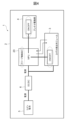
- FIG. 4 is a block diagram showing the hardware configuration of the physical quantity detection device according to this embodiment.
- the strain sensor 1 includes a physical quantity detection device 2 that detects a physical quantity of the tire using a sensor signal representing the amount of strain.
- the physical quantity detection device 2 includes a coin battery 5, a DC/DC converter 6, an MPU (Micro Processor Unit) 20, an antenna drive section 4, and a strain detection module (strain detection section) 3.
- the MPU 20 receives a boosted constant voltage from the coin battery 5 via the DC/DC converter 6, and supplies it to the strain detection module 3 and the antenna drive section.
- the voltage value of the coin battery 5 changes depending on temperature conditions and the like.
- the DC/DC converter 6 is provided to stabilize the voltage value supplied from the coin battery 5 to the MPU 20 and the strain detection module 3.
- the MPU 20 and the strain detection module 3 and the MPU 20 and the antenna drive unit 4 are electrically connected.
- the MPU 20 realizes power ON/OFF operations for the strain detection module 3 and the antenna drive section 4 using a semiconductor switch or the like, thereby reducing current consumption.
- the MPU 20 has a sleep function, and by shifting to sleep mode at times other than startup, it is possible to stop unnecessary clock circuit operations and the like, thereby reducing current consumption.
- FIG. 5 is a block diagram showing the configuration of the signal processing section of the physical quantity detection device according to the present embodiment.
- the MPU 20 of the physical quantity detection device 2 embodies a signal processing unit as an internal function by executing a program in the memory by a processor in the MPU 20.
- the MPU 20 may be referred to as the signal processing section 20.
- the signal processing unit 20 performs serial communication with the strain detection module 3 or reads analog voltage within a specified time preset in the energization timer setting unit 206 according to a regularly generated activation command. By this, the strain value is measured. The measured strain value is transmitted from the measurement unit 201 to the energization timing calculation unit 21 along with information on the time at the measured point.
- the energization timing calculation unit 21 includes a peak calculation unit 202 and a time calculation unit 203.
- the peak calculation unit 202 calculates the peak value of the strain that occurs on either compression or tension when the tire 10 rotates and the strain detection area 10a of the tire 10 comes into contact with the road surface 30, and the strain that occurs on either the compression or tension side when the tire 10 rotates and the strain detection area 10a of the tire 10 contacts the road surface 30.
- An intermediate point peak value of strain occurring on either the compression or tension side is calculated at an intermediate point in time up to the beginning of kicking when the strain detection region 10a separates from the road surface 30.
- the peak calculation unit 202 calculates a positive level (compression side) midpoint peak value 42 and a negative level (tension side) depression peak value 43 and kick-out peak value 44 of the sensor signal waveform 40. Then, the time tPa at the point where the depression peak value 43 was measured and the time tPb at the point where the intermediate point peak value 42 was measured are extracted.
- the time calculation unit 203 calculates a time difference t between the initial depression peak value 43 calculated by the peak calculation unit 202 and the intermediate point peak value 42, and calculates the time difference t between the initial depression peak value 43 calculated by the peak calculation unit 202 and the depression peak value that occurs next after the tire 10 rotates once. 43 and the time t Pb -1 until the intermediate point peak 42 are calculated.
- the relationship between the time difference between the depression peak value 43 and the intermediate point peak value 42 and the time required for the tire 10 to rotate once is proportional. In a relationship. Therefore, by using the time difference t between the first depression peak value 43 and the intermediate peak value 42, the timing at which the next depression peak 43 and the intermediate peak value 42 occur can be calculated.
- the energization timing calculation unit 21 calculates the energization timing values (t Pa-1 , t Pb-1 ) is calculated.
- the energization control section 22 is responsible for controlling the energization of the strain detection module 3 and the antenna drive section 4.
- the energization control section 22 includes a correction parameter setting section 207 and a count setting section 208.
- the correction parameter setting section 207 sets a correction parameter for correcting the width of the energization time during which energization is performed at the depression peak value 43 and the intermediate point peak value 42 that occur after the tire rotates once, which are calculated by the time calculation section 203. .
- the count setting unit 208 sets the number of times the peak value is measured.
- the feature point extraction unit 205 selects a peak value from among the plurality of measured values that is within a preset threshold value. A feature point having a peak value of is extracted, data of the peak value of the feature point is provided to the antenna driving section 4, and outputted from the antenna driving section 4 to the outside.
- the antenna driving unit 4 transmits the feature point data supplied from the feature point extraction unit 205 to the receiver 102 of the vehicle 100 by wireless communication, and provides the data to the control unit 101. By doing so, the communication time in the antenna driving section 4 can be shortened, and the current consumption can be further reduced. Note that the feature point data may be transmitted each time the measurement unit 201 measures the peak value of the strain value.
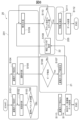
- FIG. 6 is an example of a flowchart showing the processing of the signal processing unit according to the present embodiment.
- the processing performed by the signal processing unit 20 is performed by strain detection mounted in a direction in which the sensor signal waveform 40 of the strain sensor 1 moves according to the rotational state of the tire 10, as shown in FIGS. 3(1) to (5).
- module 3 the moment when the strain detection area 10a of the tire 10 touches or separates from the road surface 30 (when stepping on or kicking off) is minus (compression), and the strain detection area 10a of the tire 10 is An example will be explained in which the state of being in contact with the road surface 30 (intermediate point) is defined as plus (tension).
- the energization timer setting unit 206 sets energization timer setting 1, which is a predetermined data acquisition period (S101). Then, the measurement unit 201 measures the strain value detected by the strain detection module 3 and sets it as the first measurement value (S102). Next, the first measured value and the reference level 41 are compared (S103), and if the measured value is less than the reference level 41 (No in S103), the energization timer setting section 206 sets the energization timer setting 2 (S104). ), performs normal measurement (S105), and performs peak extraction processing (S106).
- step S103 if the measured value is equal to or higher than the reference level 41 (Yes in S103), it is excluded from normal measurement, and it is determined whether or not the predetermined time set in energization timer setting 1 has elapsed. Comparison processing in step S103 is performed. If the time is longer than the predetermined time, it is determined that the vehicle is not running stably, and the process proceeds to the next step.
- the strain detection area 10a of the tire 10 contacts the road surface 30 due to the rotation of the tire 10, and the peak value of the strain that occurs on either the compression or tension side when the tire 10 is rotated, and the strain of the tire 10 from the time of depression.
- An intermediate point peak value of strain occurring on either the compression or tension side is extracted at an intermediate point in time until the beginning of kicking when the strain detection region 10a separates from the road surface 30.
- the peak extraction process S106 it is determined whether the plus level peak value 42 and the minus level peak value 43 are both aligned.
- the peak value 42 of the positive level for example, a measured value at the time when the measured value changes from increasing to decreasing, or a measured value at the point when the time differential at the time of measurement detects a change from positive to negative may be used.
- the negative level peak value 43 for example, the measured value at the time when the measured value changes from decreasing to increasing, or the measured value at the point where the time differential at the time of measurement detects a change from negative to positive can be used.
- the energization timing value is set (S107). Then, the process moves to the energization control section 22, and the correction parameter setting section 207 sets the correction parameters (S108). Then, intermittent energization of the strain detection module 3 is performed based on the corrected energization timing value, and intermittent measurement of the strain value (S109), that is, measurement of the strain value is performed only during energization.
- step S106 if it is determined that both the positive level peak value 42 and the negative level peak value 43 are not equal (No in S106), it is determined that the vehicle is not running stably, and the process moves to the next process. By doing this, we can eliminate cases where the car is stopped, stopped or started during measurement, and calculate cases where stable driving does not start within a certain period of time, or the peak value 42 of a positive level and the peak value 43 of a negative level. If both of these conditions are not met, it is determined that stable running is not possible, and unnecessary energization time can be shortened to achieve lower current consumption.
- Peak values are pinpoint measured by the intermittent measurement in step S109, and when the number of measured peak values becomes equal to or exceeds the count number (number of measurements) set in the count setting unit 208 (Yes in S110), the feature point extraction unit 205 extracts a feature point from the multiple measurement values (peak values) (S111), and data on the feature point is transmitted from the antenna driving unit 4 to the receiver 102 (S112).
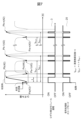
- FIG. 7 is a graph showing an example of waveform data measured by the physical quantity detection device according to the present embodiment and whether or not electricity is applied at that time.
- the waveform shows time on the horizontal axis and strain amount on the vertical axis, where the solid line portion indicates the state in which the strain detection module 3 is energized, and the dotted line portion indicates the state in which the strain detection module 3 is not energized. It shows.
- the measurement unit 201 FIG. 5
- the measurement unit 201 measures the strain value and time.
- the first measured value is compared with the reference level 41 (see FIG. 3 (5)) (S103 in FIG. 6), and since the first measured value is less than the reference level 41, Until the time point peak value 42, normal measurement is performed in which changes in strain values are continuously measured (S105 in FIG. 6).
- the energization timing calculation unit 21 calculates the energization timing that is the time between the pedal pressure Pb-1) and the negative level depression peak value 43 (Pa-1 in FIG. 7). Thereafter, the energization timing is set so that the energization is performed at the repetition for the n counts set in the count setting section 208 (FIG. 5), which sets the repetition for the required n number of rotations, at the intermediate point peak value 42, and at the depression peak value 43. Then, the current is applied in accordance with the current application timing, and the strain value is measured intermittently.
- the relationship between the time difference t between the depression peak value 43 and the intermediate point peak value 42 and the time it takes for the tire 10 to rotate once is a proportional relationship. Therefore, the next peak time is calculated using the following formula using a period conversion coefficient (proportionality constant).
- the period conversion coefficient is a unique value determined from the outer diameter of the tire.
- the values of the peak times t Pa-1 and t Pb-1 described above are determined by the energization timing calculation section 21 (FIG. 5), and set in the energization control section 22 (FIG. 5) to control the energization of the strain detection module 3.
- This enables intermittent measurement. Note that when the strain detection module 3 is not energized, the signal processing section 20 is in a sleep mode, but when returning from sleep mode, the return time is set so that the energization control to the strain detection module 3 is in time. need to be considered. That is, FIG. 7 shows a waveform in which energization starts before the peak appears.
- the energization control unit 22 de-energizes the peak value 42 of the positive level, for example, when the measured value changes from increasing to decreasing, or when the time differential at the time of measurement changes to negative.
- the negative level peak value 43 is also de-energized, for example, when the measured value changes from decreasing to increasing, or when the time differential at the time of measurement changes to positive.
- the strain detection module 3 is energized from the first depression peak value 43 (Pa in FIG. 7) to the first intermediate peak value 42 (Pb in FIG. 7), and between the next and subsequent depression peak values 43. This is performed at the timing when the point-in-time peak value 42 occurs. Then, during the time when the strain detection module 3 is not energized, the signal processing section 20 is in sleep mode. Therefore, it is possible to reduce the current consumption of the physical quantity detection device 2.
- the energization timing calculation unit 21 may calculate the cycle in which the subsequent depression peak value 43 and the intermediate point peak value 42 occur using at least two depression peak values.
- FIG. 8 is a schematic diagram showing an example of a means for correcting the energization time width at time t Pa-1 processed by the physical quantity detection device according to the present embodiment.
- the horizontal axis represents the time difference t between the positive level peak value 42 (peak value Pb in FIG. 7) and the negative level peak value 43 (peak value Pa in FIG. 7), and the vertical axis represents the next peak value.
- It is a graph showing time t Pa- 1 of Pa-1. In this graph, as the vehicle speed increases, the time difference t between peak value 42 and peak value 43 becomes smaller, indicating that the time t Pa-1 of the next peak value Pa-1 on the vertical axis becomes shorter.
- the thick line typ in the center of the upward-sloping graph in FIG. 8 is a reference graph of the time difference t and the set time t Pa-1 .
- the line max shown on the + side with respect to the standard graph type represents the relationship when the tire outer diameter becomes larger than the standard due to an increase in air pressure, etc. It shows.
- the time difference until the next peak value occurs when the tire outer diameter increases is longer than tPa -1 calculated from the time difference t between peak value 43 and peak value 42, so the next time The time t Pa-1 of the peak value 43 that occurs is corrected by + ⁇ .
- the line min shown on the negative side with respect to the reference graph typ shows the relationship when the tire outer diameter becomes smaller than the reference due to a decrease in air pressure or the like.
- the time difference until the next peak value occurs when the tire outer diameter becomes smaller is shorter than tPa -1 calculated from the time difference t between peak value 43 and peak value 42, so the next time The time t Pa-1 of the peak value 43 that occurs is corrected by - ⁇ .
- factors that vary the tire outer diameter include parameters such as the load on the tire and the amount of wear on the tire. If the parameters of the fluctuation factor are known in advance through estimation or wireless communication from the host system, the values can be used to directly correct the reference graph type to shorten the energization time width. Also good.
- FIG. 9 shows a measured waveform when the peak value of the strain value is measured multiple times.
- the count setting section 208 (FIG. 4) sets the number of times, and the measured value is extracted by the feature point extraction section 205.
- the measured values have variations within a certain range, and values that deviate from the certain range due to, for example, the tire 10 stepping on gravel, can be determined to be irregular values and excluded from the feature points. can.
- only feature points with peak values within a preset threshold are extracted from multiple peak values measured a set number of times, and measured values with irregular values are excluded from the feature points. be done.
- an abnormal value is a road surface type such as gravel based on the range of determination threshold values, and that information is transmitted, which can be used depending on the purpose while achieving low current consumption. Can be done.
- FIG. 10 is a timing chart showing whether or not each block of the physical quantity detection device according to the present embodiment is energized.
- the signal processing section 20 except when the strain detection module 3 is measuring and when the antenna driving section 4 is transmitting data, the signal processing section 20 is put into a sleep mode to realize low current consumption.
- the strain detection module 3 calculates the occurrence time t Pa-1 of the peak value 43 and the occurrence of the peak value 42, which is determined from the time difference t between the first peak value 43 and the peak value 42, as described above. Intermittent energization using time tPb-1 achieves low current consumption.
- the transmission time will be longer and the current consumption will increase during that time, and if the data is transmitted in parallel with the measurement, There is also a concern that the current used per hour increases and the power supply voltage supplied from the coin battery 5 (FIG. 4) becomes temporarily unstable.
- the strain measurement by the strain detection module 3 and the data transmission of the measured value by the antenna drive unit 4 are divided into two parts and performed at different timings. ing. This reduces the current used per hour and stabilizes the power supply voltage.
- the physical quantity detection device 2 of this embodiment can achieve a longer product life due to lower current consumption.
- the strain sensor 1 in this embodiment is composed of a strain detection module 3.
- FIG. 11 is a plan view of the strain detection module 3, and FIG. 12 is a cross-sectional view taken along line AA in FIG.
- the strain detection module 3 includes a strain detection element 3a, a base member 3b, a sealing part 3c, and an electric wire part 3d.
- the strain detection element 3a is a semiconductor that outputs a strain amount according to a change in electrical resistance, and is, for example, a strain sensor chip that is integrated into a single chip with a control circuit that performs strain detection processing.
- the strain sensor chip is an IC chip manufactured by a semiconductor process, and is, for example, a rectangular MOSFET type sensor chip with a size of about 5 mm x 5 mm. Further, the strain sensor chip is configured by, for example, a semiconductor formed by a CMOS process and a microelectromechanical system (MEMS). Note that if the strain sensor chip is large, there is a risk of damage when the tire 10 rides on a foreign object, so it is preferably smaller than 5 mm x 5 mm. Note that the strain detection element 3a is not limited to a strain sensor chip, and for example, a strain gauge may be used.
- the base member 3b is a member that fixes the strain detection element 3a to the inner peripheral surface of the tire, and is, for example, a thin metal plate having a coefficient of linear expansion close to that of the semiconductor material (Si, etc.) forming the strain detection element 3a.
- a metal with a linear expansion coefficient close to that of a semiconductor material (Si, etc.) is 42 Alloy, which has a linear expansion coefficient of about 5 ppm/°C, which is about 1 ppm/°C, which is about 1 ppm/°C different from the linear expansion coefficient of silicon (Si), which is about 4 ppm/°C.
- An alloy containing iron and nickel) can be used.
- the strain detection accuracy of the strain detection element 3a can be improved.
- the base member 3b is not limited to the above metals.
- metals that are resistant to corrosion against sulfur gas generated from tires may be used. .
- the base member 3b is a rectangular thin plate in order to accurately transmit tire strain to the strain detection element 3a. Further, the base member 3b has an arcuate end in the +Z direction (front side) as shown in FIG. Note that the shape of the base member 3b is not limited to the above, and may be a circle, an ellipse, or another polygon.
- the strain detection element 3a is fixed to the surface (+Z side surface) of the base member 3b with an adhesive, for example, a hard epoxy adhesive.
- the sealing part 3c includes a bonding wire (not shown) that electrically connects the strain detection element 3a and the electric wire part 3d, and a resin, such as epoxy, applied to the surface of the base member 3b from above the strain detection element 3a. It is resin.
- the strain sensing element 3a and the bonding wire are sealed and protected from the external environment by the sealing portion 3c.
- the sealing portion 3c is not limited to epoxy resin, and other resins such as urethane resin or silicone resin may be used.
- the electric wire portion 3d is an electric wire that electrically connects the strain detection element 3a to a circuit, and is, for example, a flexible printed circuit (FPC).
- the strain detection element 3a is a semiconductor, for example, a semiconductor strain sensor, which outputs a strain amount according to a change in resistance. This enables measurement with low power consumption (for example, about 1/1,000) and high sensitivity (for example, about 25,000 times) compared to strain gauges.
- the present invention is not limited to the above-described embodiments, and can be modified in various ways without departing from the spirit or gist of the present invention as described in the claims.
- the design can be changed.
- the embodiments described above have been described in detail to explain the present invention in an easy-to-understand manner, and the present invention is not necessarily limited to having all the configurations described.
- it is possible to replace a part of the configuration of one embodiment with the configuration of another embodiment and it is also possible to add the configuration of another embodiment to the configuration of one embodiment.
- SYMBOLS 1 Strain sensor, 2... Physical quantity detection device, 3... Strain detection module (strain detection part), 3a... Strain detection element, 3b... Base member, 3c... Sealing part , 3d... Electric wire section, 4... Antenna drive section, 5... Coin battery, 6... DC/DC converter, 10... Tire, 20... Signal processing section, 21... Energization timing calculation unit, 22... Energization control unit, 30... Road surface, 40... Sensor signal waveform, 41... Reference level, 42... Peak value of positive level, 43...
Landscapes
- Physics & Mathematics (AREA)
- General Physics & Mathematics (AREA)
- Engineering & Computer Science (AREA)
- Mechanical Engineering (AREA)
- Automation & Control Theory (AREA)
- Mathematical Physics (AREA)
- Transportation (AREA)
- Arrangements For Transmission Of Measured Signals (AREA)
- Tires In General (AREA)
Priority Applications (5)
| Application Number | Priority Date | Filing Date | Title |
|---|---|---|---|
| US19/111,666 US20260104301A1 (en) | 2022-09-16 | 2022-09-16 | Physical quantity detection device |
| EP22958833.0A EP4589273A4 (en) | 2022-09-16 | 2022-09-16 | DEVICE FOR DETECTING A PHYSICAL QUANTITY |
| PCT/JP2022/034691 WO2024057513A1 (ja) | 2022-09-16 | 2022-09-16 | 物理量検出装置 |
| CN202280099820.3A CN119836565A (zh) | 2022-09-16 | 2022-09-16 | 物理量检测装置 |
| JP2024546649A JP7797673B2 (ja) | 2022-09-16 | 2022-09-16 | 物理量検出装置 |
Applications Claiming Priority (1)
| Application Number | Priority Date | Filing Date | Title |
|---|---|---|---|
| PCT/JP2022/034691 WO2024057513A1 (ja) | 2022-09-16 | 2022-09-16 | 物理量検出装置 |
Publications (1)
| Publication Number | Publication Date |
|---|---|
| WO2024057513A1 true WO2024057513A1 (ja) | 2024-03-21 |
Family
ID=90274780
Family Applications (1)
| Application Number | Title | Priority Date | Filing Date |
|---|---|---|---|
| PCT/JP2022/034691 Ceased WO2024057513A1 (ja) | 2022-09-16 | 2022-09-16 | 物理量検出装置 |
Country Status (5)
| Country | Link |
|---|---|
| US (1) | US20260104301A1 (https=) |
| EP (1) | EP4589273A4 (https=) |
| JP (1) | JP7797673B2 (https=) |
| CN (1) | CN119836565A (https=) |
| WO (1) | WO2024057513A1 (https=) |
Citations (6)
| Publication number | Priority date | Publication date | Assignee | Title |
|---|---|---|---|---|
| JP2005088662A (ja) * | 2003-09-16 | 2005-04-07 | Toyota Motor Corp | タイヤ状態量検出装置 |
| JP2009248783A (ja) * | 2008-04-08 | 2009-10-29 | Panasonic Corp | タイヤ空気圧モニタ装置、その制御方法、およびプログラム |
| JP2015217713A (ja) * | 2014-05-14 | 2015-12-07 | 株式会社ブリヂストン | タイヤ情報送信装置 |
| US20160303928A1 (en) * | 2013-12-05 | 2016-10-20 | Continental Automotive France | Method for determining a wheel tire ground print |
| WO2019142869A1 (ja) * | 2018-01-19 | 2019-07-25 | 株式会社デンソー | タイヤシステム |
| JP2022520499A (ja) * | 2019-03-29 | 2022-03-30 | ノキアン レンカート オーイーユィ | タイヤ |
Family Cites Families (6)
| Publication number | Priority date | Publication date | Assignee | Title |
|---|---|---|---|---|
| DE102007039242A1 (de) * | 2007-08-20 | 2009-02-26 | Robert Bosch Gmbh | Verfahren zum Betrieb eines Sensors an oder in einem Fahrzeugreifen und Sensoranordnung |
| JP7009098B2 (ja) * | 2017-07-19 | 2022-01-25 | 株式会社ブリヂストン | 路面状態推定方法 |
| JP6930355B2 (ja) * | 2017-10-11 | 2021-09-01 | 株式会社Soken | 路面状態判別装置およびそれを備えたタイヤシステム |
| US20190118592A1 (en) * | 2017-10-19 | 2019-04-25 | Infineon Technologies Ag | Method, Tire-Mounted TPMS Component, and Machine Readable Storage or Computer Program for Determining a Duration of at Least one Contact Patch Event of a Rolling Tire |
| WO2020126646A1 (en) * | 2018-12-18 | 2020-06-25 | Pirelli Tyre S.P.A. | Method and system for monitoring a tire during the running of a vehicle |
| EP3741588B1 (en) * | 2019-05-23 | 2023-03-01 | Melexis Technologies SA | Contact patch data acquisition |
-
2022
- 2022-09-16 EP EP22958833.0A patent/EP4589273A4/en active Pending
- 2022-09-16 CN CN202280099820.3A patent/CN119836565A/zh active Pending
- 2022-09-16 WO PCT/JP2022/034691 patent/WO2024057513A1/ja not_active Ceased
- 2022-09-16 JP JP2024546649A patent/JP7797673B2/ja active Active
- 2022-09-16 US US19/111,666 patent/US20260104301A1/en active Pending
Patent Citations (7)
| Publication number | Priority date | Publication date | Assignee | Title |
|---|---|---|---|---|
| JP2005088662A (ja) * | 2003-09-16 | 2005-04-07 | Toyota Motor Corp | タイヤ状態量検出装置 |
| JP2009248783A (ja) * | 2008-04-08 | 2009-10-29 | Panasonic Corp | タイヤ空気圧モニタ装置、その制御方法、およびプログラム |
| US20160303928A1 (en) * | 2013-12-05 | 2016-10-20 | Continental Automotive France | Method for determining a wheel tire ground print |
| JP2015217713A (ja) * | 2014-05-14 | 2015-12-07 | 株式会社ブリヂストン | タイヤ情報送信装置 |
| JP6317999B2 (ja) | 2014-05-14 | 2018-04-25 | 株式会社ブリヂストン | タイヤ情報送信装置 |
| WO2019142869A1 (ja) * | 2018-01-19 | 2019-07-25 | 株式会社デンソー | タイヤシステム |
| JP2022520499A (ja) * | 2019-03-29 | 2022-03-30 | ノキアン レンカート オーイーユィ | タイヤ |
Non-Patent Citations (1)
| Title |
|---|
| See also references of EP4589273A4 |
Also Published As
| Publication number | Publication date |
|---|---|
| JP7797673B2 (ja) | 2026-01-13 |
| US20260104301A1 (en) | 2026-04-16 |
| EP4589273A1 (en) | 2025-07-23 |
| JPWO2024057513A1 (https=) | 2024-03-21 |
| EP4589273A4 (en) | 2025-10-15 |
| CN119836565A (zh) | 2025-04-15 |
Similar Documents
| Publication | Publication Date | Title |
|---|---|---|
| JP4503078B2 (ja) | タイヤ回転検出装置、タイヤ回転検出方法及びタイヤ監視装置 | |
| EP1862425B1 (en) | Method for estimating tire slip angle and tire with sensor | |
| US8063756B2 (en) | Tire pressure monitor having capability of accurately detecting state of motion of vehicle | |
| US7504763B2 (en) | Power generator | |
| US7243534B2 (en) | Tire state quantity detecting apparatus and method | |
| CN114585523B (zh) | 轮胎磨损量估计系统、轮胎磨损量估计程序以及轮胎磨损量估计方法 | |
| CN106427419A (zh) | 车辆轮胎内的电能产生 | |
| WO2024057513A1 (ja) | 物理量検出装置 | |
| JP4426146B2 (ja) | 空気タイヤに取り付けられるパッチ | |
| JP4296917B2 (ja) | タイヤ状態推定装置およびタイヤ | |
| JP3872367B2 (ja) | タイヤ状態量推定装置 | |
| JP4165393B2 (ja) | 車輪状態判定装置 | |
| US20250153520A1 (en) | Step detection device | |
| KR20090012784A (ko) | 타이어 정보 모니터링 시스템 | |
| CN117871084B (zh) | 空气弹簧衰减检测方法及相关装置 | |
| KR100581104B1 (ko) | 타이어 공기압 감지 장치 | |
| JP2008044600A (ja) | タイヤ空気圧異常警報方法、装置およびプログラム | |
| JP2005212552A (ja) | タイヤ空気圧低下検出方法および装置、ならびにタイヤ減圧判定のプログラム | |
| JPH07253436A (ja) | 回転速度センサ |
Legal Events
| Date | Code | Title | Description |
|---|---|---|---|
| 121 | Ep: the epo has been informed by wipo that ep was designated in this application |
Ref document number: 22958833 Country of ref document: EP Kind code of ref document: A1 |
|
| WWE | Wipo information: entry into national phase |
Ref document number: 2024546649 Country of ref document: JP |
|
| WWE | Wipo information: entry into national phase |
Ref document number: 202280099820.3 Country of ref document: CN |
|
| WWP | Wipo information: published in national office |
Ref document number: 202280099820.3 Country of ref document: CN |
|
| WWE | Wipo information: entry into national phase |
Ref document number: 2022958833 Country of ref document: EP |
|
| NENP | Non-entry into the national phase |
Ref country code: DE |
|
| ENP | Entry into the national phase |
Ref document number: 2022958833 Country of ref document: EP Effective date: 20250416 |
|
| WWP | Wipo information: published in national office |
Ref document number: 2022958833 Country of ref document: EP |