WO2024057370A1 - カバー、エアロゾル生成装置 - Google Patents
カバー、エアロゾル生成装置 Download PDFInfo
- Publication number
- WO2024057370A1 WO2024057370A1 PCT/JP2022/034118 JP2022034118W WO2024057370A1 WO 2024057370 A1 WO2024057370 A1 WO 2024057370A1 JP 2022034118 W JP2022034118 W JP 2022034118W WO 2024057370 A1 WO2024057370 A1 WO 2024057370A1
- Authority
- WO
- WIPO (PCT)
- Prior art keywords
- sensor
- cover
- main body
- unit
- heating
- Prior art date
- Legal status (The legal status is an assumption and is not a legal conclusion. Google has not performed a legal analysis and makes no representation as to the accuracy of the status listed.)
- Ceased
Links
Images


Classifications
-
- A—HUMAN NECESSITIES
- A24—TOBACCO; CIGARS; CIGARETTES; SIMULATED SMOKING DEVICES; SMOKERS' REQUISITES
- A24F—SMOKERS' REQUISITES; MATCH BOXES; SIMULATED SMOKING DEVICES
- A24F40/00—Electrically operated smoking devices; Component parts thereof; Manufacture thereof; Maintenance or testing thereof; Charging means specially adapted therefor
- A24F40/50—Control or monitoring
- A24F40/51—Arrangement of sensors
-
- A—HUMAN NECESSITIES
- A24—TOBACCO; CIGARS; CIGARETTES; SIMULATED SMOKING DEVICES; SMOKERS' REQUISITES
- A24F—SMOKERS' REQUISITES; MATCH BOXES; SIMULATED SMOKING DEVICES
- A24F40/00—Electrically operated smoking devices; Component parts thereof; Manufacture thereof; Maintenance or testing thereof; Charging means specially adapted therefor
- A24F40/20—Devices using solid inhalable precursors
-
- A—HUMAN NECESSITIES
- A24—TOBACCO; CIGARS; CIGARETTES; SIMULATED SMOKING DEVICES; SMOKERS' REQUISITES
- A24F—SMOKERS' REQUISITES; MATCH BOXES; SIMULATED SMOKING DEVICES
- A24F40/00—Electrically operated smoking devices; Component parts thereof; Manufacture thereof; Maintenance or testing thereof; Charging means specially adapted therefor
- A24F40/40—Constructional details, e.g. connection of cartridges and battery parts
- A24F40/46—Shape or structure of electric heating means
-
- A—HUMAN NECESSITIES
- A24—TOBACCO; CIGARS; CIGARETTES; SIMULATED SMOKING DEVICES; SMOKERS' REQUISITES
- A24F—SMOKERS' REQUISITES; MATCH BOXES; SIMULATED SMOKING DEVICES
- A24F40/00—Electrically operated smoking devices; Component parts thereof; Manufacture thereof; Maintenance or testing thereof; Charging means specially adapted therefor
- A24F40/50—Control or monitoring
- A24F40/53—Monitoring, e.g. fault detection
-
- A—HUMAN NECESSITIES
- A24—TOBACCO; CIGARS; CIGARETTES; SIMULATED SMOKING DEVICES; SMOKERS' REQUISITES
- A24F—SMOKERS' REQUISITES; MATCH BOXES; SIMULATED SMOKING DEVICES
- A24F40/00—Electrically operated smoking devices; Component parts thereof; Manufacture thereof; Maintenance or testing thereof; Charging means specially adapted therefor
- A24F40/60—Devices with integrated user interfaces
-
- A—HUMAN NECESSITIES
- A24—TOBACCO; CIGARS; CIGARETTES; SIMULATED SMOKING DEVICES; SMOKERS' REQUISITES
- A24F—SMOKERS' REQUISITES; MATCH BOXES; SIMULATED SMOKING DEVICES
- A24F40/00—Electrically operated smoking devices; Component parts thereof; Manufacture thereof; Maintenance or testing thereof; Charging means specially adapted therefor
- A24F40/65—Devices with integrated communication means, e.g. wireless communication means
Definitions
- the present disclosure relates to a cover and an aerosol generation device.
- the suction device described in Patent Document 1 includes an operation section that accepts an operation by a user, and a biological information detection section that detects biological information of the user, and the biological information detection section is configured to It is placed near the operation section.
- the purpose of this disclosure is to provide a cover etc. that allows confirmation of external information.
- the present disclosure completed with such an objective is a cover attached to a main body having a heating part that heats a base material including an aerosol source, the cover including internal information related to the state of the main body and the state of the cover.
- a communication unit that communicates with a sensor that detects external information other than related internal information; and an output unit that outputs the external information detected by the sensor to an external device other than the cover via the communication unit.
- the sensor may be provided at either end in the centerline direction of a columnar holding part formed in the main body so as to accommodate a part of the base material.
- the sensor further includes a plurality of connecting portions connected to the main body, and the sensor includes a plurality of connecting portions connected to the main body in a center line direction of a columnar holding portion formed on the main body so as to accommodate a part of the base material. It may be provided closer to the opening of the holding portion than the connecting portion. Further, the sensor detects temperature or humidity, and the output unit outputs to the external device that the temperature or humidity is appropriate for storing the base material, based on the temperature or humidity detected by the sensor. You may do so. Furthermore, when the sensor fails, the output unit may output to the external device that the sensor has failed.
- the communication unit is capable of communicating through a plurality of wireless communications having different communication distances, and one antenna among the plurality of antennas used for each of the plurality of wireless communications is configured to communicate with an aerosol source.
- the other antenna is provided at one end of both ends in the center line direction of a columnar holding part formed on the main body to accommodate a part of the base material holding the main body, and the other antenna is provided at the other end. It may be provided in Furthermore, from another perspective, the present disclosure is an aerosol generation device including a main body having a heating section that heats a base material including an aerosol source, and the cover of the above disclosure attached to the main body.
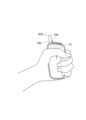
- FIG. 3 is a diagram showing an example of a state in which the generating device is held with the right hand.
- FIG. 3 is a diagram showing an example of a state in which the generating device is held in the left hand.
- FIG. 3 is a diagram showing an example of information stored in a storage unit. It is a figure which shows an example of the information which the output part output to the portable terminal. It is a figure which shows an example of the information which the output part output to the portable terminal. It is a flowchart which shows an example of the heating control process performed by a control part. It is a flowchart which shows an example of the on-off control process performed by a control part. It is a figure which shows an example of the information which the output part output to the portable terminal. 11 is a diagram illustrating an example of a correspondence relationship between sensors and whether or not output to a portable terminal is required. FIG.
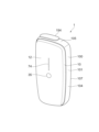
- FIG. 1 is an example of a view of the aerosol generation device 1 viewed diagonally from above.
- FIG. 2 is an example of a view of the aerosol generation device 1 viewed diagonally from below.
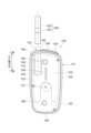
- FIG. 3 is an example of a front view of the main body 100 with the cover 10 removed.
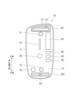
- FIG. 4 is an example of a view of the cover 10 viewed from the rear side.
- FIG. 5 is an example of a diagram schematically showing a configuration example of the main body 100.
- FIG. 6 is an example of a diagram schematically showing the configuration of the cover 10. As shown in FIG.
- the aerosol generation device 1 (hereinafter sometimes simply referred to as the "generation device 1") includes a heating section that heats a base material 500 (hereinafter sometimes simply referred to as the "base material 500") including an aerosol source. 170, and a cover 10 that is removable from the main body 100.
- the main body 100 has a substantially rectangular parallelepiped-shaped housing 101 that accommodates a heating section 170 and the like.
- the cover 10 covers one side of the housing 101.
- the side to which the cover 10 is attached is the front side 102, the left side when viewed from the front 102 side is the left side 103, the right side is the right side 104, and the upper side is the top side. 105, the lower surface is referred to as a bottom surface 106.
- a surface connected to the left side 103, right side 104, top surface 105, and bottom surface 106, and which is different from the front surface 102 is referred to as a back surface 107.
- the cover 10 covers the front surface 102 of the housing 101, and the left side surface 103, right side surface 104, top surface 105, bottom surface 106, and back surface 107 are exposed to the outside with the cover 10 attached.
- the main body 100 includes a power supply section 110, a sensor section 120, a notification section 130, a storage section 140, a communication section 150, a control section 160, a heating section 170, and a heat insulation section 180. , and a holding section 190.
- the power supply section 110 , the sensor section 120 , the notification section 130 , the storage section 140 , the communication section 150 , the control section 160 , the heating section 170 , and the heat insulation section 180 are housed in the housing 101 .
- the main body 100 also includes a shutter 194 (see FIG. 1) that is disposed on the top surface 105 and can be slid along the top surface 105. Each component will be explained in order below.
- the power supply unit 110 includes a battery 111 that stores power and a power supply unit 112 that supplies power.
- An example of the battery 111 is a rechargeable battery such as a lithium ion secondary battery.
- the battery 111 may be charged by being connected to an external power source via a cable or the like connected to a USB (Universal Serial Bus) terminal 113. Further, the battery 111 may be charged without being connected to a power transmitting device using wireless power transmission technology. Alternatively, only the battery 111 may be removed from the main body 100, or may be replaced with a new battery 111.
- the power supply unit 112 supplies power to each component of the main body 100 based on control by the control unit 160. Further, the power supply unit 112 supplies power to the cover 10 .
- the power supply unit 112 supplies power to the cover 10 by, for example, non-contact power transmission.
- An example of contactless power transmission is power transmission using short-range wireless communication. This makes it possible to supply power to the cover 10 with a simple configuration.
- the sensor unit 120 detects various information regarding the main body 100. The sensor section 120 then outputs the detected information to the control section 160.
- the sensor section 120 is configured with a pressure sensor, a flow rate sensor, or a temperature sensor such as a microphone capacitor. When the sensor unit 120 detects a numerical value associated with suction by the user, it outputs information indicating that suction has been performed by the user to the control unit 160.
- the sensor unit 120 is configured with an input device such as a button or a switch that receives information input from the user.
- the sensor unit 120 may include a button for instructing start/stop of aerosol generation.
- the sensor unit 120 then outputs the information input by the user to the control unit 160.
- the sensor unit 120 has an operation button 121 that instructs to start generating aerosol. As shown in FIG. 3, the operation button 121 is provided so as to be exposed from the front surface 102 of the housing 101.
- the notification unit 130 notifies the user of information.
- the notification unit 130 is configured with a light emitting device such as an LED (Light Emitting Diode).
- the notification unit 130 emits light in different light emission patterns when the battery 111 of the power supply unit 110 requires charging, when the battery 111 is being charged, when an abnormality occurs in the main body 100, etc. do.
- the light emission pattern here is a concept that includes color, timing of turning on/off, and the like.
- the notification unit 130 may be configured with a display device that displays an image, a sound output device that outputs sound, a vibration device that vibrates, etc. together with or in place of the light emitting device.
- a display window 108 is formed on the front surface 102 of the housing 101 and transmits light emitted by a light emitting device such as an LED as an example of the notification section 130.
- the light emitting device is provided at the rear of the display window 108. There is.
- the storage unit 140 stores various information for the operation of the generation device 1.
- the storage unit 140 is configured by, for example, a nonvolatile storage medium such as a flash memory.
- An example of the information stored in the storage unit 140 is information regarding the OS (Operating System) of the generation device 1, such as control details of various components by the control unit 160.
- Another example of information stored in the storage unit 140 is information related to suction by the user, such as the number of suctions, the time of suction, and the cumulative suction time.
- the communication unit 150 is a communication interface for transmitting and receiving information between the generation device 1 and other devices.
- the communication unit 150 performs communication based on any wired or wireless communication standard.
- a communication standard for example, wireless LAN (Local Area Network), wired LAN, Wi-Fi (registered trademark), Bluetooth (registered trademark), etc. may be adopted.
- the communication unit 150 transmits information regarding suction by the user to another device (for example, a portable terminal 600 described below) to display the information regarding suction by the user.
- the communication unit 150 receives new OS information from a server in order to update the OS information stored in the storage unit 140.
- the control unit 160 functions as an arithmetic processing device and a control device, and controls overall operations within the generation device 1 according to various programs.
- the control unit 160 is realized by, for example, an electronic circuit such as a CPU (Central Processing Unit) and a microprocessor.
- the control unit 160 may include a ROM (Read Only Memory) that stores programs to be used, calculation parameters, etc., and a RAM (Random Access Memory) that temporarily stores parameters that change as appropriate.
- the generation device 1 executes various processes based on control by the control unit 160.
- the heating unit 170 atomizes the aerosol source to generate aerosol by heating the aerosol source.
- the heating section 170 is made of any material such as metal or polyimide.
- the heating unit 170 is configured in a film shape and is arranged to cover the outer periphery of the holding unit 190. Then, when the heating section 170 generates heat, the aerosol source included in the base material 500 is heated from the outer periphery of the base material 500 and atomized, thereby generating an aerosol.
- the heating unit 170 generates heat when supplied with power from the power supply unit 110, and heats the base material 500. When the temperature of the base material 500 heated by the heating unit 170 reaches a predetermined temperature, suction by the user becomes possible. Thereafter, when the sensor unit 120 detects that a predetermined user input has been performed, the power supply may be stopped.
- the heat insulating section 180 prevents heat transfer from the heating section 170 to other components of the generation device 1 .
- the heat insulating section 180 is arranged to cover at least the outer periphery of the heating section 170.
- the heat insulating section 180 is made of a vacuum heat insulating material, an airgel heat insulating material, or the like.
- Vacuum insulation material is an insulation material that reduces heat conduction by gas to as close to zero as possible by wrapping glass wool, silica (silicon powder), etc. in a resin film and creating a high vacuum state. be.
- the holding part 190 has a columnar internal space 191 provided inside the housing 101 and an opening 192 formed in the upper surface 105 of the housing 101 to communicate the internal space 191 to the outside.
- the internal space 191 is a cylindrical body having a bottom portion 193 as a bottom surface.
- the holding part 190 is configured such that its inner diameter is smaller than the outer diameter of the base material 500 in at least a portion of the height direction of the cylindrical body, and holds the base material 500 inserted into the internal space 191 from the opening 192 around the outer periphery.
- the base material 500 can be held by being compressed.
- the holding portion 190 also has the function of defining an air flow path through the base material 500.
- An air inlet hole which is an entrance for air into the flow path, is arranged, for example, at the bottom portion 193.
- the air outlet hole which is the outlet of the air from the flow path, is the opening 192.
- the opening 192 is exposed by sliding the shutter 194 to the open position and hidden by sliding the shutter 194 to the closed position.
- the shutter 194 has a magnet on its back surface.
- a magnetic sensor included in the sensor section 120 is attached to the upper surface 105 of the housing 101 within the movable range of the shutter 194.
- the magnetic sensor is a Hall IC composed of a Hall element, an operational amplifier, etc., and outputs a voltage according to the strength of the magnetic field that crosses the Hall element.
- control unit 160 detects opening and closing of shutter 194 from changes in voltage output from the magnetic sensor as shutter 194 slides.
- the base material 500 is a stick-shaped member.
- the base material 500 includes a base material part 501 and a mouthpiece part 502.
- Base portion 501 includes an aerosol source.
- the aerosol source is heated and atomized to produce an aerosol.
- the aerosol source may be derived from tobacco, such as a processed product formed from shredded tobacco or tobacco raw material into granules, sheets, or powder. Aerosol sources may also include non-tobacco sources made from plants other than tobacco, such as mint and herbs. As an example, the aerosol source may include a fragrance ingredient such as menthol. If the generating device 1 is a medical inhaler, the aerosol source may contain a medicament for inhalation by the patient.
- the aerosol source is not limited to solids, and may be, for example, polyhydric alcohols such as glycerin and propylene glycol, and liquids such as water. At least a portion of the base material part 501 is accommodated in the internal space 191 of the holding part 190 while the base material 500 is held by the holding part 190.
- the suction part 502 is a member that is held in the user's mouth during suction. At least a portion of the mouthpiece 502 protrudes from the opening 192 when the base material 500 is held by the holding part 190. Then, when the user holds the suction port 502 protruding from the opening 192 and sucks it, air flows into the holding part 190 from an air inflow hole (not shown). The inflowing air passes through the internal space 191 of the holding part 190, that is, passes through the base material part 501, and reaches the user's mouth together with the aerosol generated from the base material part 501.
- the main body 100 is provided so as to be exposed from the front surface 102 of the housing 101, and has two magnets used for connection with the cover 10, an upper magnet 195 and a lower magnet 196.
- the upper magnet 195 and the lower magnet 196 have a circular cylindrical shape when viewed from the front.
- the centers of the circles of the upper magnet 195 and the lower magnet 196 are arranged in the direction of the center line of the base material 500 by the holding part 190 (hereinafter sometimes simply referred to as the "center line direction"), and the upper magnet 195 and the lower magnet 196 are A magnet 195 is provided at the top of the main body 100, and a lower magnet 196 is provided at the bottom of the main body 100.
- the main body 100 has an operation button 121 provided at the center in the center line direction so as to be exposed from the front surface 102 of the housing 101.
- the operation button 121 is arranged between the upper magnet 195 and the lower magnet 196.
- the main body 100 has a display window 108 above the operation button 121 and between the upper magnet 195 and the operation button 121 that allows light from a light emitting device such as an LED to pass through to a display window 74 (described later) of the cover 10.
- the display window 108 is a window provided at a position corresponding to the position of the light emitting device arranged in the housing 101 of the main body 100, and allows light from the light emitting device to pass through to the display window 74 of the cover 10. This allows the user to visually recognize the light from the outer surface of the cover 10.
- the main body 100 has a magnetic sensor 122.
- the magnetic sensor 122 detects magnetic force based on a magnetic field applied from a magnet 75 of the cover 10, which will be described later.
- the magnetic sensor 122 is preferably a Hall sensor configured using a Hall element. Thereby, attachment of the cover 10 to the main body 100 can be detected.
- the cover 10 includes a cover body 11, a power supply section 20, a sensor section 30, a storage section 40, a communication section 50, and a control section 60.
- the cover main body 11 is formed into a plate shape from a light-transmitting member, covers the front surface 102 of the housing 101 of the main body 100, and has steps formed on the left side 103, right side 104, top surface 105, and bottom surface 106 of the housing 101. It is molded so that it does not occur. Thereby, the cover 10 forms an appearance that is integrated with the left side 103, right side 104, top surface 105, and bottom surface 106 of the housing 101, and has a decorative function. Further, the cover 10 has a function of suppressing the propagation of heat emitted from the main body 100.
- the power supply section 20, the sensor section 30, the storage section 40, the communication section 50, and the control section 60 are attached to the cover body 11.
- the power supply section 20 includes a battery 21 that stores power, a power supply section 22 that supplies power to each component of the cover 10, and a power reception section 23 that receives power from the power supply section 112 of the power supply section 110 of the main body 100.
- the battery 21 can be exemplified as a rechargeable battery such as a lithium ion secondary battery formed in a film shape, for example.
- the battery 21 is charged by the power supplied to the cover 10 from the power supply section 112 of the power supply section 110 of the main body 100.
- the power supply unit 22 supplies power from the battery 21 to each component of the cover 10. Further, the power feeding unit 22 supplies the power received by the power receiving unit 23 to each component of the cover 10 . As a result, each component of the cover 10 including the sensor section 30 can be operated by the power supplied from the main body 100 to the cover 10.
- the power receiving unit 23 includes an NFC (Near Field Communication) reader/writer module, an NFC antenna, etc. It consists of:
- the sensor unit 30 includes an ambient air sensor that detects information about the air surrounding the generation device 1 .
- Air information can be exemplified by temperature and humidity. That is, the sensor unit 30 includes, as an example of an ambient air sensor, a temperature sensor that can detect the temperature (for example, room temperature) around the generation device 1 and a humidity sensor that can detect the surrounding humidity.
- the air information may be atmospheric pressure, and the sensor unit 30 may have an atmospheric pressure sensor capable of detecting the atmospheric pressure around the generation device 1 as an example of an ambient air sensor.
- the sensor unit 30 may include a vital sensor that detects the user's biological information.
- the vital sensor can be exemplified as a sensor capable of detecting any one of the user's body temperature, heart rate, pulse rate, blood oxygen saturation, blood flow, and COHb (carbohemoglobin).
- An example of a sensor that detects the user's body temperature is a sensor that converts infrared rays emitted from the forehead or the like into body temperature.
- a sensor that detects at least one of heart rate, pulse rate, blood oxygen saturation, blood flow, and COHb includes a light-emitting element that emits light onto the human body, and a sensor that transmits the light emitted by the light-emitting element through the user's body.
- An example of an optical sensor includes a light-receiving element that receives light, and outputs information regarding the light received by the light-receiving element.
- the light emitting element is a light source, and is realized by, for example, an LED or the like.
- the light receiving element is realized by, for example, a photodiode or the like.
- the light received by the light receiving element is, for example, reflected light from a human body. This reflected light includes light scattered and reflected within the human body (ie, scattered light).
- the vital sensor may be a sensor that can detect the alcohol concentration in the user's breath.
- the sensor unit 30 may include a distance sensor capable of detecting the distance between the generation device 1 and the target object, or a color sensor capable of detecting the color of the target object.
- the sensor unit 30 includes a touch sensor 35 that detects that the user is touching the cover 10. Since suction can be started by the user touching the touch sensor 35, FIG. 1 and the like show an example in which the touch sensor 35 is disposed at the center of the generating device 1 in the center line direction. However, the position of the touch sensor 35 is not limited to the position shown in FIG. 1 and the like.
- a sensor that detects external information may be referred to as an "external sensor 31.”
- the external sensor 31 is a general term for sensors that detect external environment information of the generation device 1, such as a temperature sensor, humidity sensor, and atmospheric pressure sensor, a vital sensor that detects biometric information of the user, a distance sensor, and a color sensor.
- the external information includes biological information such as body temperature, heart rate, pulse rate, blood oxygen saturation, blood flow, COHb, and alcohol concentration, and external environmental information such as temperature and humidity.
- the storage unit 40 stores various information for the operation of the cover 10.
- the storage unit 40 is composed of, for example, a nonvolatile storage medium such as a flash memory.
- An example of the information stored in the storage unit 40 is information related to the OS (Operating System) of the cover 10, such as control details of various components by the control unit 60.
- the storage unit 40 stores information acquired from the sensor unit 30.
- the storage unit 40 also stores a predetermined temperature range and a predetermined humidity range, which will be described later.
- the communication unit 50 is a communication interface for transmitting and receiving information between the cover 10 and an external device other than the cover 10.
- the communication unit 50 performs communication based on any wired or wireless communication standard.
- a communication standard for example, wireless LAN (Local Area Network), wired LAN, Wi-Fi (registered trademark), Bluetooth (registered trademark), etc. may be adopted.
- the external device is a device other than the main body 100 or the generation device 1, and the device other than the generation device 1 is a multifunction mobile phone (so-called “smartphone") owned by the user.Hereinafter, may be referred to as a "mobile phone”. ), etc., or a server (not shown).
- the portable terminal 600 may be a tablet terminal, a tablet PC, a personal digital assistant (PDA), or a notebook PC.
- the communication unit 50 transmits information detected by the sensor unit 30 to a mobile phone. Furthermore, the communication unit 50 receives new OS information from the server in order to update the OS information stored in the storage unit 40.
- the communication unit 50 may communicate with the main body 100 by, for example, short-range wireless communication.
- short-range wireless communication As described above, power is supplied from the main body 100 to the cover 10 by short-range wireless communication, and the communication unit 50 communicates with the main body 100 by short-range wireless communication, so that the main body 100 and Communication and power transmission with the cover 10 can be efficiently realized, and the configurations of the main body 100 and the cover 10 can be simplified.
- the communication unit 50 is connected to the power receiving unit. This can be realized using the same NFC reader/writer module, NFC antenna, etc. as in No. 23.
- the communication unit 50 may communicate with the main body 100 via this power supply interface.
- the control unit 60 functions as an arithmetic processing device and a control device, and controls overall operations within the cover 10 according to various programs.
- the control unit 60 is realized by, for example, an electronic circuit such as a CPU and a microprocessor.
- the control unit 60 may include a ROM that stores programs to be used, calculation parameters, etc., and a RAM that temporarily stores parameters that change as appropriate.
- the cover 10 executes various processes based on control by the control unit 60.
- the control unit 60 controls power supply from the power supply unit 20 to other components, charging of the power supply unit 20, detection by the sensor unit 30, storage and reading of information by the storage unit 40, and transmission and reception of information by the communication unit 50. This is an example of the processing performed.
- Other processes executed by the cover 10, such as inputting information to each component and processing based on information output from each component, are also controlled by the control unit 60.
- control unit 60 transmits and receives data to and from the control unit 160 of the main body 100 via the communication unit 50.
- the control unit 60 transmits the detected value of the sensor unit 30 to the control unit 160 of the main body 100.
- the control unit 60 receives from the control unit 160 of the main body 100, for example, information that heating of the heating unit 170 has started or that heating has stopped.
- the cover 10 has an upper magnet 71 and a lower magnet 72 on the back surface 13 of the cover main body 11, which is the surface on the main body 100 side.
- the upper magnet 71 and the lower magnet 72 have a circular cylindrical shape when viewed from the rear side, and are provided at positions corresponding to the upper magnet 195 and the lower magnet 196 provided on the main body 100, respectively.
- the upper magnet 71 and the lower magnet 72 are arranged in the direction of the center line, and the upper magnet 71 is provided on the upper part of the cover 10 and the lower magnet 72 is provided on the lower part of the cover 10.
- the cover 10 is attached to the main body 100 by the attraction between the magnets.
- the cover 10 is not limited to being attached to the main body 100 by the attraction force between magnets.
- the cover 10 and the main body 100 may have a structure in which they physically fit together.
- the physical fitting structure is a structure in which a fitting claw provided on one member of the cover 10 or the main body 100 (for example, the cover 10) is fitted into a hole or a recess formed in the other member (for example, the main body 100). It can be exemplified that
- the touch sensor 35 described above is provided between the upper magnet 71 and the lower magnet 72, in other words, at the center of the cover 10 in the center line direction.
- the position of the touch sensor 35 is not limited.
- the touch sensors 35 may be provided at multiple locations.
- a display window 74 is formed in the cover body 11 between the upper magnet 71 and the lower magnet 72 and above the touch sensor 35.
- the display window 74 is provided at a position corresponding to the display window 108 provided in the main body 100.
- the cover body 11 is made of a material that transmits light. Thereby, the cover 10 transmits light emitted from the light emitting element provided in the main body 100 to the front surface 12 of the cover main body 11.
- the cover 10 has a magnet 75 on the left side in FIG. 4 of the line connecting the upper magnet 71 and the lower magnet 72.
- the magnet 75 is provided at a position corresponding to the magnetic sensor 122 provided on the main body 100, and attachment of the cover 10 to the main body 100 is detected by the magnetic sensor 122 provided on the main body 100.
- the external sensor 31 of the sensor unit 30 is located at both ends of the cover 10 in the center line direction, in other words, the first region R1 is located above the upper magnet 71 and below the lower magnet 72, as shown in FIG. Preferably, it is provided in either of the second regions R2.
- the external sensor 31 is a light sensor
- a light emitting element emits light to a finger or the like placed in front of the front surface 12 of the cover body 11, and the light emitted by the light emitting element is received via the finger or the like. Therefore, if dirt adheres to the area through which the light passes, it will be difficult to detect with high accuracy.
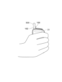
- FIG. 7 is a diagram showing an example of a state in which the generation device 1 is held with the right hand.
- FIG. 8 is a diagram showing an example of a state in which the generating device 1 is held in the left hand.
- FIG. 4 shows an example in which the external sensor 31 is provided in the first region R1.
- the external sensor 31 is provided in the first region R1.
- the hand is on the side (upper side) of the opening 192 of the holding part 190 than the upper magnet 71. Since the area where the external sensor 31 is arranged is difficult to be touched by hand.
- the external sensor 31 is arranged in an area that is difficult to touch by the user, dirt is difficult to adhere to the front surface 12 of the cover 10, so that highly accurate detection is possible.
- the external sensor 31 may be provided in the second region R2 below the lower magnet 72. This is because even in the second region R2, even if the generating device 1 is held with the right hand or the left hand when suctioning with the generating device 1, the position corresponds to the little finger, and it is difficult for the user to apply a load to the second region R2.
- the external sensor 31 is a sensor other than an optical sensor (for example, a temperature sensor or a humidity sensor), by arranging it in the first region R1 or the second region R2, it is possible to make it difficult for the user to apply a load. Therefore, the external sensor 31 can be made less likely to fail.
- an optical sensor for example, a temperature sensor or a humidity sensor
- the control unit 60 includes an output unit 61 (see FIG. 6) that outputs information detected by the external sensor 31 of the sensor unit 30 to an external device via the communication unit 50.
- the output unit 61 outputs, for example, the temperature and humidity detected by the temperature sensor and humidity sensor, which are examples of the external sensor 31, to the portable terminal 600. This allows the user to check information about the surrounding air using the portable terminal 600.
- FIG. 9 is a diagram showing an example of information stored in the storage unit 40.
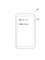
- 10 and 11 are diagrams showing examples of information outputted by the output unit 61 to the portable terminal 600.
- the output unit 61 outputs to the portable terminal 600 that the temperature or humidity is appropriate for storing the base material 500 based on the temperature or humidity detected by the temperature sensor or the humidity sensor.
- the storage unit 40 stores a predetermined temperature range (hereinafter sometimes referred to as a "predetermined temperature range”) as a temperature range suitable for storing the base material 500. put. Then, when the temperature detected by the temperature sensor is within the predetermined temperature range, the output unit 61 outputs to the portable terminal 600 the temperature detected by the temperature sensor as well as the fact that the temperature is appropriate for storage. As a result, as shown in FIG. 10, the display unit 601 of the portable terminal 600 displays that the temperature is appropriate for storage.
- An example of the predetermined temperature range is 10°C to 28°C, preferably 17°C to 21°C.
- the storage unit 40 stores a predetermined humidity range (hereinafter sometimes referred to as a "predetermined humidity range”) as a humidity range suitable for storing the base material 500. put. Then, when the humidity detected by the humidity sensor is within the predetermined humidity range, the output unit 61 outputs to the portable terminal 600 the humidity detected by the humidity sensor and a message that the humidity is appropriate for storage. As a result, as shown in FIG. 10, the display unit 601 of the portable terminal 600 displays that the humidity is appropriate for storage.
- An example of the predetermined humidity range is 66% to 74%, preferably 68% to 72%.
- the storage unit 40 stores a predetermined temperature range as a temperature range suitable for storing the base material 500, and also stores a predetermined humidity range as a humidity range suitable for storage. Then, when the temperature detected by the temperature sensor is within a predetermined temperature range and the humidity detected by the humidity sensor is within a predetermined humidity range, the output unit 61 outputs the temperature and humidity detected by the temperature sensor. It is preferable to output to the portable terminal 600, along with the detected humidity, information that the temperature and humidity are appropriate for storage.
- the output unit 61 outputs information detected by the vital sensor included in the sensor unit 30 to the portable terminal 600.
- the vital sensor detects at least one of the user's body temperature, heart rate, pulse rate, blood oxygen saturation, blood flow, COHb, and alcohol concentration
- the output unit 61 detects the user's body temperature, heart rate, pulse rate, blood oxygen saturation, blood flow, COHb, and alcohol concentration.
- the body temperature, heart rate, pulse rate, blood oxygen saturation, blood flow, COHb, and/or alcohol concentration are output to the portable terminal 600.
- the sensor unit 30 has a vital sensor that detects the user's body temperature and heart rate, and the output unit 61 outputs the body temperature and heart rate detected by the vital sensor to a portable terminal 600, and the output unit 61 outputs the body temperature and heart rate detected by the vital sensor to a portable terminal 600.
- a mode is shown in which body temperature and heart rate are displayed on the display unit 601 of the terminal 600. By displaying in this manner, the user can check information regarding his or her own body on the portable terminal 600.
- the control unit 160 of the main body 100 allows generation of aerosol when the cover 10 is attached. That is, the control unit 160 allows the heating unit 170 to heat when the cover 10 is attached to the main body 100. In other words, the cover 10 allows the heating unit 170 to be heated by the main body 100 by being attached to the main body 100. As described above, the control unit 160 is able to determine whether the cover 10 is attached to the main body 100 using the output value of the Hall sensor.
- control section 160 of the main body 100 may control the heating of the heating section 170 based on the output of the sensor section 30 of the cover 10. Thereby, it becomes possible to operate the generation device 1 appropriately according to the user's condition.
- the quality of the suction experience (for example, smoking experience) that the user can experience by using the generating device 1 may depend on the user's own physical condition. Therefore, even if the aerosol source and flavor source match the user's preferences, if the user is not feeling well, the user may not be able to obtain a high-quality suction experience. In this way, it is preferable to generate aerosol in the generation device 1 even though the user cannot obtain a high-quality suction experience, as this will lead to waste of the aerosol source and the flavor source. do not have.
- the generating device 1 it may also be possible to disallow heating of the
- the predetermined range of the detection value of the vital sensor that permits heating of the heating unit 170 may be referred to as a "predetermined permission range.”
- the predetermined permitted range can be 38° C. or lower.
- the predetermined permitted range can be exemplified as 65 to 85 bpm (beats/min).
- the vital sensor is a sensor capable of detecting the user's pulse rate
- the predetermined permission range can be exemplified as 65 to 100 bpm (times/min).
- the vital sensor is a sensor capable of detecting blood oxygen saturation
- the predetermined permission range can be exemplified as 96% or more.
- the predetermined permitted range can be exemplified as 20 to 60 ml/min/100 g. Further, when the vital sensor is a sensor capable of detecting COHb, the predetermined permission range can be exemplified as less than 2%. Further, when the vital sensor is an alcohol sensor capable of detecting the alcohol concentration in exhaled breath, the predetermined permitted range can be exemplified as 0.20 mg or less.
- the storage unit 140 stores a predetermined permission range for each biometric information.
- the control unit 160 of the main body 100 may acquire the detection value of the vital sensor from the cover 10 and may not permit heating of the heating unit 170 if the detection value is outside a predetermined permitted range.
- FIG. 12 is a flowchart illustrating an example of the heating control process performed by the control unit 160.
- the control unit 160 repeatedly executes this process at preset fixed time intervals (for example, 1 millisecond).
- the control unit 160 determines whether there is a heating instruction (S1201).
- An example of the heating instruction can be that the touch sensor 35 is continuously touched for a predetermined period of time (for example, 3 seconds). If there is a heating instruction (YES in S1201), the control unit 160 determines whether the cover 10 is attached (S1202). This process is a process for determining whether the magnetic sensor 122 has detected magnetic force.
- the control unit 160 determines whether the value detected by the vital sensor is within a predetermined permissible range (S1203). Then, if it is within the predetermined permission range (YES in S1203), the control unit 160 starts heating the heating unit 170 (S1204). Further, the control unit 160 transmits to the control unit 60 of the cover 10 that the heating unit 170 has started heating. Then, the control unit 160 heats the heating unit 170 according to a control sequence that is stored in the storage unit 140 of the main body 100 and defines a temporal change in the target temperature of the heating unit 170 when heating the heating unit 170, and then heats the heating unit 170. stop. After stopping the heating of the heating unit 170, the control unit 160 transmits to the control unit 60 of the cover 10 that the heating of the heating unit 170 has been stopped.
- control unit 160 does not start heating the heating unit 170 (S1205).
- control unit 160 of the main body 100 allows the heating unit 170 to heat when the detection value of the vital sensor is within the predetermined permission range, thereby allowing the user to have a high-quality suction experience and reducing the aerosol source, etc. You can prevent this from leading to waste.
- control unit 160 may permit heating of the heating unit 170 without being based on the detected value of the vital sensor.
- control unit 160 may perform heating without making the determination in S1203 of FIG. 12 when the cover 10 is attached (YES in S1202). It is only necessary to start heating the section 170.
- control unit 160 may allow the heating unit 170 to heat even if the cover 10 is not attached.
- control unit 160 may control the detection value of the vital sensor within the predetermined permission range without making the determination in S1202 of FIG. If so (YES in S1203), heating of the heating unit 170 may be started.
- the switch of the touch sensor 35 may be off when the heating section 170 of the main body 100 is heating. Then, when the heating section 170 of the main body 100 is heating, the touch sensor 35 is turned off, and the touch sensor 35 no longer outputs the on signal, so that the external sensor 31 may be turned off. In this way, it is possible to save energy by turning off the touch sensor 35 and the external sensor 31 while the heating section 170 of the main body 100 is heating.
- FIG. 13 is a flowchart illustrating an example of the on/off control process performed by the control unit 60.
- the control unit 60 is activated, for example, when the touch sensor 35 detects that the user is touching the cover 10, and executes the process illustrated in FIG. 13 at preset intervals (for example, 1 millisecond). Execute repeatedly.
- control unit 60 transmits to the control unit 160 of the main body 100 that the control unit 60 has been activated (S1301). Then, the control unit 60 turns on the switch of the external sensor 31 (S1302), and transmits the detected value of the external sensor 31 to the control unit 160 of the main body 100 (S1303). After that, the control unit 60 determines whether the heating unit 170 of the main body 100 has started heating (S1304). This is a process in which the control unit 60 determines whether or not it has received a notification from the control unit 160 of the main body 100 that heating of the heating unit 170 has started.
- the control unit 60 When heating is started (YES in S1304), the control unit 60 turns off the switch of the touch sensor 35 (S1305). When the touch sensor 35 is off, the touch sensor 35 no longer outputs an on signal, so the control unit 60 turns off the external sensor 31 (S1306). After that, the control unit 60 determines whether the heating unit 170 of the main body 100 has stopped heating (S1307). If the heating has not been stopped (NO in S1307), the control unit 60 waits until the heating is stopped.
- the control unit 60 When heating is stopped (YES in S1307), the control unit 60 turns on the switch of the touch sensor 35 (S1308). After that, the control unit 60 determines whether the touch sensor 35 detects that the user is touching the cover 10 (S1309). If the touch sensor 35 detects the touch (YES in S1309), the control unit 60 performs the processes from S1302 onwards. On the other hand, if the touch sensor 35 does not detect it (NO in S1309), the control unit 60 transmits to the control unit 160 of the main body 100 that the control unit 60 will turn off the power (S1310), and turns off the power. (S1311). On the other hand, if heating has not started (NO in S1304), the control unit 60 performs the processes from S1309 onwards.
- FIG. 14 is a diagram showing an example of information outputted by the output unit 61 to the portable terminal 600.
- the output unit 61 of the control unit 60 outputs to the portable terminal 600 that the external sensor 31 has failed.
- the display unit 601 of the portable terminal 600 displays that the humidity sensor has failed. Examples of failures in the external sensor 31 include disconnections and short circuits.
- the output unit 61 may output to the portable terminal 600 depending on the type of the external sensor 31. For example, the output unit 61 outputs to the portable terminal 600 when the vital sensor, temperature sensor, and humidity sensor are out of order, and does not output to the portable terminal 600 when the atmospheric pressure sensor, distance sensor, and color sensor are out of order. You can do it like this.
- the reason why the vital sensor is output to the portable terminal 600 when the vital sensor fails is because heating of the heating unit 170 is not permitted unless the detected value of the vital sensor is within a predetermined permitted range. This is because it may become impossible to inhale aerosols. Furthermore, the reason why the temperature sensor and the humidity sensor are output to the portable terminal 600 when they fail is because it is not possible to notify the user that the temperature and humidity are within the predetermined range.
- the types of external sensors 31 that output to the portable terminal 600 in the event of failure and the types of external sensors 31 that do not output to the portable terminal 600 even if they fail are not particularly limited. You can set it arbitrarily.
- FIG. 15 is a diagram illustrating an example of the correspondence between sensors and whether output to the portable terminal 600 is necessary.
- the storage unit 40 stores, for each external sensor 31 included in the sensor unit 30, whether or not to output to the portable terminal 600 that the external sensor 31 has failed. In the example shown in FIG. 15, the storage unit 40 needs to output to the portable terminal 600 when the vital sensor, temperature sensor, and humidity sensor are out of order, and when the air pressure sensor, distance sensor, and color sensor are out of order. It is stored that there is no need to output to the portable terminal 600.
- the output unit 61 outputs the portable terminal 600 if it is stored in the storage unit 40 that it is necessary to notify when the sensor fails. If the storage unit 40 stores that it is unnecessary to output to the sensor and notify when the sensor fails, it is preferable not to output to the portable terminal 600.
- the output unit 61 when a vital sensor malfunctions, if it is stored that it is necessary to notify that the vital sensor has failed, the output unit 61 outputs a message indicating that the vital sensor has failed. is output to the portable terminal 600. On the other hand, as shown in FIG. 15, for example, if it is stored that there is no need to notify that the atmospheric pressure sensor has failed, the output unit 61 notifies the portable terminal 600 that the atmospheric pressure sensor has failed. Prevent it from being output.
- the cover 10 is a cover 10 that is attached to the main body 100 that has the heating section 170 that heats the base material 500 containing the aerosol source.
- the cover 10 includes an external sensor 31 as an example of a sensor that detects internal information related to the state of the main body 100 (for example, the temperature of the heating section 170) and external information other than the internal information related to the state of the cover 10. It includes a communication unit 50 that performs communication, and an output unit 61 that outputs external information detected by the external sensor 31 to an external device other than the cover 10 (for example, a portable terminal 600) via the communication unit 50.
- the user can read biological information such as body temperature, heart rate, pulse rate, blood oxygen saturation, blood flow, COHb, alcohol concentration, etc., and external environmental information such as temperature and humidity. can be confirmed using, for example, the portable terminal 600, thereby increasing user convenience.
- biological information such as body temperature, heart rate, pulse rate, blood oxygen saturation, blood flow, COHb, alcohol concentration, etc.
- external environmental information such as temperature and humidity.
- the external sensor 31 is preferably provided at either end in the centerline direction of the columnar holding portion 190 formed on the main body 100 so as to accommodate a part of the base material 500. This makes it difficult for the user to apply a load to the external sensor 31, making it difficult for the external sensor 31 to fail.
- the cover 10 further includes an upper magnet 71 and a lower magnet 72 as an example of a plurality of connecting parts connected to the main body 100, and the external sensor 31 is attached to the main body 100 so as to accommodate a part of the base material 500. It is preferable that the opening 192 of the holding part 190 be provided closer to the opening 192 of the holding part 190 than the upper magnet 71 and the lower magnet 72 in the direction of the center line of the formed columnar holding part 190 .
- the area closer to the opening 192 (upper side) than the upper magnet 71 is an area that is difficult to touch by the user even if the generating device 1 is held with the right or left hand during suction, so dirt is unlikely to adhere to the front surface 12 of the cover 10. Therefore, highly accurate detection is possible.
- the external sensor 31 detects temperature or humidity, and the output unit 61 outputs an external device (for example, it is output to a portable terminal 600).
- the cover 10 configured in this way, the user can confirm the appropriate place to store the base material 500 using, for example, the portable terminal 600, thereby increasing the user's convenience. Moreover, it becomes possible to store the base material 500 in an appropriate place.
- the output unit 61 outputs the fact that the external sensor 31 has failed to an external device (for example, the portable terminal 600). This makes it possible to notify the user that the external sensor 31 has failed.
- the cover 10 has a plurality of sensors (for example, a temperature sensor, a vital sensor, etc.), and further includes a storage unit 40 that stores, for each sensor, whether or not it is necessary to notify when the sensor breaks down. .
- the output unit 61 outputs an external device (e.g. If it is stored in the storage unit 40 that it is unnecessary to output to the portable terminal 600) and notify when the sensor has failed, it is not output to the external device.
- an external device e.g. If it is stored in the storage unit 40 that it is unnecessary to output to the portable terminal 600
- notify when the sensor has failed it is not output to the external device.
- compared to a configuration in which failures of all sensors are output to an external device it is possible to achieve energy savings.
- Wi-Fi (registered trademark) and Bluetooth (registered trademark) use overlapping frequency bands, so if Wi-Fi (registered trademark) and Bluetooth (registered trademark) are used at the same time, their radio waves may interfere with each other. This is to prevent the communication speed from slowing down or being disconnected.
- one of the two antennas is provided at one end of both ends in the center line direction, and the other antenna is provided at the other end of both ends in the center line direction.
- the first antenna 51 for Wi-Fi (registered trademark) is provided in the first region R1 above the upper magnet 71
- the second antenna 52 for Bluetooth registered trademark
- it is provided in the second region R2 below the lower magnet 72.
- the communication unit 50 of the cover 10 can communicate using multiple wireless communications (Wi-Fi (registered trademark), Bluetooth (registered trademark)) that have different communication distances.
- a first antenna 51 (an example of one antenna) among the plurality of antennas used for each of the plurality of wireless communications is formed in the main body 100 so as to accommodate a part of the base material 500 holding the aerosol source.
- the second antenna 52 (an example of another antenna) is provided at the other end of the columnar holding portion 190 in the center line direction. Thereby, it is possible to prevent the communication speed from slowing down or the connection from being disconnected due to interference between radio waves caused by using a plurality of wireless communications at the same time.
- the cover 10 configured as described above has the battery 21, so even if the cover 10 is not attached to the main body 100, the external sensor 31 can detect temperature, humidity, biological information, etc. It can be detected and output to the portable terminal 600. Therefore, there is no need for the user to carry the main body 100 when searching for an appropriate place to store the base material 500.
- the amount of power per unit time that can be supplied from the power supply unit 112 of the main body 100 to the cover 10 by contactless power transmission such as short-range wireless communication is small, components that can be mounted on the cover 10 only by contactless power transmission (For example, the external sensor 31) is limited, but by providing the battery 21, the degree of freedom of components that can be mounted on the cover 10 can be improved.
- the battery 21 is not provided on the cover 10, and when the cover 10 is attached to the main body 100 or the cover 10 is present in the vicinity of the main body 100, the battery 21 is not provided with the battery 21, and when the cover 10 is attached to the main body 100 or the cover 10 is present in the vicinity of the main body 100, the battery 21 is The cover 10 may be operated only by electric power.
- the types of sensors included in the external sensor 31 may be different for each type of cover 10.
- one cover 10 may have only a temperature sensor, a humidity sensor, and an atmospheric pressure sensor, and the other cover 10 may have only a vital sensor.
- This allows the user to change the functions provided by the generating device 1 by replacing the cover 10.
- the appearance of the generating device 1 can be changed by replacing the cover 10. Therefore, the user can, for example, customize the appearance and functions of the generation device 1 according to his or her own preferences. As a result, the marketability of the generation device 1 can be improved.
- the cover 10 by configuring the cover 10 to be detachable from the main body 100, for example, if the main body 100 breaks down, it is possible to replace only the main body 100 and use the cover 10 as is. Since the cover 10 has the storage section 40, when only the main body 100 is replaced, the information stored in the storage section 140 of the main body 100 can be transferred to the storage section 40 of the cover 10.
- the information stored in the storage unit 140 of the main body 100 includes the heating control process described using FIG. It can be exemplified that it is a program.
- the information may be transferred by contactless power transmission such as short-range wireless communication, or by providing a USB terminal on the cover 10 and connecting a cable between the USB terminal and the USB terminal 113 of the main body 100. Transmission may also be performed by connecting.
- the cover 10 it is determined whether or not there is an instruction to heat the heating unit 170 by touching the touch sensor 35 provided in the center, but the present invention is not limited to this embodiment.
- a protrusion protruding from the back surface 13 toward the main body 100 is provided at a position between the upper magnet 71 and the lower magnet 72 corresponding to the operation button 121 of the main body 100, and the cover 10 is elastically deformed so that the protrusion is attached to the protrusion.
- the operation button 121 is operated in a predetermined manner (for example, in a manner in which it is pressed continuously for 3 seconds), it is possible to determine whether or not there is a heating instruction. You can judge. Even in such a configuration, it is preferable to provide the touch sensor 35 on the cover 10 to detect that the user is touching the cover 10, and to turn on the external sensor 31 when the user is touching the cover 10.
- a cover comprising: a sensor for detection; a communication section for communicating; and an output section for outputting the external information detected by the sensor to an external device other than the cover via the communication section.
- the sensor further includes a plurality of connecting portions connected to the main body, and the sensor is arranged in a direction along a center line of a columnar holding portion formed on the main body so as to accommodate a part of the base material.
- the cover according to (1) which is provided closer to the opening of the holding portion than the connecting portion.
- the sensor detects temperature or humidity, and the output unit indicates to the external device that the temperature or humidity is appropriate for storing the base material, based on the temperature or humidity detected by the sensor.
- the cover according to any one of (1) to (4) wherein, when the sensor fails, the output unit outputs to the external device that the sensor has failed.
- a plurality of the sensors are provided, and each of the sensors includes a storage unit that stores whether or not it is necessary to notify when the sensor fails, and the output unit includes a plurality of the sensors. If any of the above sensors malfunctions, if the storage unit stores that it is necessary to notify when the sensor malfunctions, output to the external device, and when the sensor malfunctions, The cover according to (5), which does not output to the external device if the storage unit stores that the notification is unnecessary.
- the communication unit is capable of communicating through a plurality of wireless communications having different communication distances, and one of the plurality of antennas used for each of the plurality of wireless communications is configured to transmit an aerosol.
- the antenna is provided at one end of both ends in the center line direction of a columnar holding part formed on the main body so as to accommodate a part of the base material holding the source, and the other antenna is provided at the other end.
- the cover according to any one of (1) to (6), which is provided in the section.
- An aerosol generation device comprising: a main body having a heating section that heats a base material including an aerosol source; and a cover according to any one of (1) to (7) attached to the main body.
- SYMBOLS 1...Aerosol generation device 10...Cover, 30...Sensor part, 31...External sensor (an example of a sensor), 35...Touch sensor, 40...Storage part, 50...Communication part, 51...First antenna (one antenna) example), 52... second antenna (an example of another antenna), 60... control section, 61... output section, 71... upper magnet (an example of a connecting section), 72... lower magnet (an example of a connecting section), 100... Main body (an example of an external device), 170... heating section, 190... holding section, 192... opening, 500... base material, 600... portable terminal (an example of an external device)
Landscapes
- Engineering & Computer Science (AREA)
- Computer Networks & Wireless Communication (AREA)
- Human Computer Interaction (AREA)
- Measuring And Recording Apparatus For Diagnosis (AREA)
- Investigating Or Analyzing Materials By The Use Of Fluid Adsorption Or Reactions (AREA)
- Arrangements For Transmission Of Measured Signals (AREA)
- Infusion, Injection, And Reservoir Apparatuses (AREA)
Priority Applications (6)
| Application Number | Priority Date | Filing Date | Title |
|---|---|---|---|
| JP2024546530A JP7846948B2 (ja) | 2022-09-12 | 2022-09-12 | カバー、エアロゾル生成装置 |
| CN202280099903.2A CN119855513A (zh) | 2022-09-12 | 2022-09-12 | 罩、气溶胶生成装置 |
| EP22958705.0A EP4588380A1 (en) | 2022-09-12 | 2022-09-12 | Cover, and aerosol generation device |
| PCT/JP2022/034118 WO2024057370A1 (ja) | 2022-09-12 | 2022-09-12 | カバー、エアロゾル生成装置 |
| KR1020257011433A KR20250059526A (ko) | 2022-09-12 | 2022-09-12 | 커버, 에어로졸 생성 장치 |
| US19/073,070 US20250194674A1 (en) | 2022-09-12 | 2025-03-07 | Cover, and aerosol generation device |
Applications Claiming Priority (1)
| Application Number | Priority Date | Filing Date | Title |
|---|---|---|---|
| PCT/JP2022/034118 WO2024057370A1 (ja) | 2022-09-12 | 2022-09-12 | カバー、エアロゾル生成装置 |
Related Child Applications (1)
| Application Number | Title | Priority Date | Filing Date |
|---|---|---|---|
| US19/073,070 Continuation US20250194674A1 (en) | 2022-09-12 | 2025-03-07 | Cover, and aerosol generation device |
Publications (1)
| Publication Number | Publication Date |
|---|---|
| WO2024057370A1 true WO2024057370A1 (ja) | 2024-03-21 |
Family
ID=90274411
Family Applications (1)
| Application Number | Title | Priority Date | Filing Date |
|---|---|---|---|
| PCT/JP2022/034118 Ceased WO2024057370A1 (ja) | 2022-09-12 | 2022-09-12 | カバー、エアロゾル生成装置 |
Country Status (6)
| Country | Link |
|---|---|
| US (1) | US20250194674A1 (https=) |
| EP (1) | EP4588380A1 (https=) |
| JP (1) | JP7846948B2 (https=) |
| KR (1) | KR20250059526A (https=) |
| CN (1) | CN119855513A (https=) |
| WO (1) | WO2024057370A1 (https=) |
Citations (6)
| Publication number | Priority date | Publication date | Assignee | Title |
|---|---|---|---|---|
| JP2017538449A (ja) * | 2014-12-16 | 2017-12-28 | シン,ジョンス | 電子タバコ |
| JP2020068739A (ja) * | 2018-11-02 | 2020-05-07 | 日本たばこ産業株式会社 | エアロゾル供給デバイス及び個人用健康状態評価システム |
| JP2020068689A (ja) * | 2018-10-30 | 2020-05-07 | 日本たばこ産業株式会社 | エアロゾル生成装置の電源ユニット、エアロゾル生成装置の電源ユニットの制御方法、およびエアロゾル生成装置の電源ユニット用プログラム |
| JP2021516540A (ja) * | 2018-03-14 | 2021-07-08 | フィリップ・モーリス・プロダクツ・ソシエテ・アノニム | バイオセンサーを備えたエアロゾル発生システム |
| JP2021530969A (ja) * | 2018-07-10 | 2021-11-18 | フィリップ・モーリス・プロダクツ・ソシエテ・アノニム | 空気質センサーを備えたエアロゾル生成システム |
| WO2021240617A1 (ja) | 2020-05-25 | 2021-12-02 | 日本たばこ産業株式会社 | 吸引装置、制御方法、及びプログラム |
Family Cites Families (3)
| Publication number | Priority date | Publication date | Assignee | Title |
|---|---|---|---|---|
| WO2021059377A1 (ja) | 2019-09-25 | 2021-04-01 | 日本たばこ産業株式会社 | バッテリユニット、情報処理方法、及びプログラム |
| KR102427856B1 (ko) | 2020-04-13 | 2022-08-01 | 주식회사 케이티앤지 | 에어로졸 생성 장치 및 이를 제어하는 방법 |
| WO2022130602A1 (ja) | 2020-12-18 | 2022-06-23 | 日本たばこ産業株式会社 | 吸引装置、端末装置、及びプログラム |
-
2022
- 2022-09-12 KR KR1020257011433A patent/KR20250059526A/ko active Pending
- 2022-09-12 CN CN202280099903.2A patent/CN119855513A/zh active Pending
- 2022-09-12 WO PCT/JP2022/034118 patent/WO2024057370A1/ja not_active Ceased
- 2022-09-12 JP JP2024546530A patent/JP7846948B2/ja active Active
- 2022-09-12 EP EP22958705.0A patent/EP4588380A1/en active Pending
-
2025
- 2025-03-07 US US19/073,070 patent/US20250194674A1/en active Pending
Patent Citations (6)
| Publication number | Priority date | Publication date | Assignee | Title |
|---|---|---|---|---|
| JP2017538449A (ja) * | 2014-12-16 | 2017-12-28 | シン,ジョンス | 電子タバコ |
| JP2021516540A (ja) * | 2018-03-14 | 2021-07-08 | フィリップ・モーリス・プロダクツ・ソシエテ・アノニム | バイオセンサーを備えたエアロゾル発生システム |
| JP2021530969A (ja) * | 2018-07-10 | 2021-11-18 | フィリップ・モーリス・プロダクツ・ソシエテ・アノニム | 空気質センサーを備えたエアロゾル生成システム |
| JP2020068689A (ja) * | 2018-10-30 | 2020-05-07 | 日本たばこ産業株式会社 | エアロゾル生成装置の電源ユニット、エアロゾル生成装置の電源ユニットの制御方法、およびエアロゾル生成装置の電源ユニット用プログラム |
| JP2020068739A (ja) * | 2018-11-02 | 2020-05-07 | 日本たばこ産業株式会社 | エアロゾル供給デバイス及び個人用健康状態評価システム |
| WO2021240617A1 (ja) | 2020-05-25 | 2021-12-02 | 日本たばこ産業株式会社 | 吸引装置、制御方法、及びプログラム |
Also Published As
| Publication number | Publication date |
|---|---|
| KR20250059526A (ko) | 2025-05-02 |
| JPWO2024057370A1 (https=) | 2024-03-21 |
| US20250194674A1 (en) | 2025-06-19 |
| JP7846948B2 (ja) | 2026-04-16 |
| EP4588380A1 (en) | 2025-07-23 |
| CN119855513A (zh) | 2025-04-18 |
Similar Documents
| Publication | Publication Date | Title |
|---|---|---|
| CN119325348A (zh) | 气溶胶生成装置的内部灭菌 | |
| US20250204584A1 (en) | Cover and aerosol generation device | |
| JP7846948B2 (ja) | カバー、エアロゾル生成装置 | |
| JP7769138B2 (ja) | エアロゾル生成装置 | |
| US20240324667A1 (en) | Inhalation device | |
| US20250176640A1 (en) | Inhalation device, control method, and storage medium | |
| JP7802186B2 (ja) | カバー部材 | |
| US20240324691A1 (en) | Inhalation device | |
| EP4608063A1 (en) | Cover member | |
| KR20250090313A (ko) | 전자 장치 및 프로그램 | |
| WO2024084608A1 (ja) | エアロゾル生成装置 | |
| US20230105963A1 (en) | Inhaler device, display device, display method, and program | |
| WO2025126331A1 (ja) | エアロゾル生成装置 | |
| WO2025126332A1 (ja) | エアロゾル生成装置 | |
| TW202500034A (zh) | 吸嚐裝置、控制方法及程式 | |
| CN120282724A (zh) | 电子装置和气溶胶产生装置 | |
| KR20250088803A (ko) | 전자 장치 및 프로그램 | |
| WO2024057373A1 (ja) | エアロゾル生成装置に着脱が可能な追加部材 |
Legal Events
| Date | Code | Title | Description |
|---|---|---|---|
| 121 | Ep: the epo has been informed by wipo that ep was designated in this application |
Ref document number: 22958705 Country of ref document: EP Kind code of ref document: A1 |
|
| WWE | Wipo information: entry into national phase |
Ref document number: 2024546530 Country of ref document: JP Ref document number: 202280099903.2 Country of ref document: CN |
|
| ENP | Entry into the national phase |
Ref document number: 20257011433 Country of ref document: KR Kind code of ref document: A |
|
| WWE | Wipo information: entry into national phase |
Ref document number: 1020257011433 Country of ref document: KR |
|
| WWE | Wipo information: entry into national phase |
Ref document number: 2022958705 Country of ref document: EP |
|
| NENP | Non-entry into the national phase |
Ref country code: DE |
|
| WWP | Wipo information: published in national office |
Ref document number: 202280099903.2 Country of ref document: CN |
|
| ENP | Entry into the national phase |
Ref document number: 2022958705 Country of ref document: EP Effective date: 20250414 |
|
| WWP | Wipo information: published in national office |
Ref document number: 2022958705 Country of ref document: EP |