WO2024057370A1 - カバー、エアロゾル生成装置 - Google Patents
カバー、エアロゾル生成装置 Download PDFInfo
- Publication number
- WO2024057370A1 WO2024057370A1 PCT/JP2022/034118 JP2022034118W WO2024057370A1 WO 2024057370 A1 WO2024057370 A1 WO 2024057370A1 JP 2022034118 W JP2022034118 W JP 2022034118W WO 2024057370 A1 WO2024057370 A1 WO 2024057370A1
- Authority
- WO
- WIPO (PCT)
- Prior art keywords
- sensor
- cover
- main body
- unit
- heating
- Prior art date
Links
- 239000000443 aerosol Substances 0.000 title claims abstract description 47
- 238000010438 heat treatment Methods 0.000 claims abstract description 95
- 238000004891 communication Methods 0.000 claims abstract description 77
- 239000000463 material Substances 0.000 claims abstract description 52
- 239000000758 substrate Substances 0.000 claims 1
- 238000000034 method Methods 0.000 description 20
- 239000003570 air Substances 0.000 description 13
- 230000005540 biological transmission Effects 0.000 description 13
- 230000036760 body temperature Effects 0.000 description 13
- 238000001514 detection method Methods 0.000 description 13
- 238000010586 diagram Methods 0.000 description 13
- QVGXLLKOCUKJST-UHFFFAOYSA-N atomic oxygen Chemical compound [O] QVGXLLKOCUKJST-UHFFFAOYSA-N 0.000 description 8
- 239000008280 blood Substances 0.000 description 8
- 210000004369 blood Anatomy 0.000 description 8
- 230000017531 blood circulation Effects 0.000 description 8
- 239000001301 oxygen Substances 0.000 description 8
- 229910052760 oxygen Inorganic materials 0.000 description 8
- 238000012545 processing Methods 0.000 description 8
- LFQSCWFLJHTTHZ-UHFFFAOYSA-N Ethanol Chemical compound CCO LFQSCWFLJHTTHZ-UHFFFAOYSA-N 0.000 description 7
- 230000006870 function Effects 0.000 description 7
- 230000007257 malfunction Effects 0.000 description 7
- 241000208125 Nicotiana Species 0.000 description 5
- 235000002637 Nicotiana tabacum Nutrition 0.000 description 5
- DNIAPMSPPWPWGF-UHFFFAOYSA-N Propylene glycol Chemical compound CC(O)CO DNIAPMSPPWPWGF-UHFFFAOYSA-N 0.000 description 3
- 239000012080 ambient air Substances 0.000 description 3
- 238000009413 insulation Methods 0.000 description 3
- PEDCQBHIVMGVHV-UHFFFAOYSA-N Glycerine Chemical compound OCC(O)CO PEDCQBHIVMGVHV-UHFFFAOYSA-N 0.000 description 2
- XEEYBQQBJWHFJM-UHFFFAOYSA-N Iron Chemical compound [Fe] XEEYBQQBJWHFJM-UHFFFAOYSA-N 0.000 description 2
- HBBGRARXTFLTSG-UHFFFAOYSA-N Lithium ion Chemical compound [Li+] HBBGRARXTFLTSG-UHFFFAOYSA-N 0.000 description 2
- VYPSYNLAJGMNEJ-UHFFFAOYSA-N Silicium dioxide Chemical compound O=[Si]=O VYPSYNLAJGMNEJ-UHFFFAOYSA-N 0.000 description 2
- 230000007613 environmental effect Effects 0.000 description 2
- 210000003811 finger Anatomy 0.000 description 2
- 239000000796 flavoring agent Substances 0.000 description 2
- 235000019634 flavors Nutrition 0.000 description 2
- 239000011810 insulating material Substances 0.000 description 2
- 239000012774 insulation material Substances 0.000 description 2
- 229910001416 lithium ion Inorganic materials 0.000 description 2
- 229910052751 metal Inorganic materials 0.000 description 2
- 239000002184 metal Substances 0.000 description 2
- 230000003287 optical effect Effects 0.000 description 2
- 239000002699 waste material Substances 0.000 description 2
- NOOLISFMXDJSKH-UTLUCORTSA-N (+)-Neomenthol Chemical compound CC(C)[C@@H]1CC[C@@H](C)C[C@@H]1O NOOLISFMXDJSKH-UTLUCORTSA-N 0.000 description 1
- NOOLISFMXDJSKH-UHFFFAOYSA-N DL-menthol Natural products CC(C)C1CCC(C)CC1O NOOLISFMXDJSKH-UHFFFAOYSA-N 0.000 description 1
- 241000196324 Embryophyta Species 0.000 description 1
- 235000006679 Mentha X verticillata Nutrition 0.000 description 1
- 235000002899 Mentha suaveolens Nutrition 0.000 description 1
- 235000001636 Mentha x rotundifolia Nutrition 0.000 description 1
- 239000004642 Polyimide Substances 0.000 description 1
- XUIMIQQOPSSXEZ-UHFFFAOYSA-N Silicon Chemical compound [Si] XUIMIQQOPSSXEZ-UHFFFAOYSA-N 0.000 description 1
- 230000005856 abnormality Effects 0.000 description 1
- 125000003158 alcohol group Chemical group 0.000 description 1
- 239000003990 capacitor Substances 0.000 description 1
- 210000000078 claw Anatomy 0.000 description 1
- 238000012790 confirmation Methods 0.000 description 1
- 230000001186 cumulative effect Effects 0.000 description 1
- 239000003814 drug Substances 0.000 description 1
- 238000005516 engineering process Methods 0.000 description 1
- 210000001061 forehead Anatomy 0.000 description 1
- 239000003205 fragrance Substances 0.000 description 1
- 239000007789 gas Substances 0.000 description 1
- 239000011491 glass wool Substances 0.000 description 1
- 235000011187 glycerol Nutrition 0.000 description 1
- 239000008187 granular material Substances 0.000 description 1
- 235000008216 herbs Nutrition 0.000 description 1
- 239000004615 ingredient Substances 0.000 description 1
- 229910052742 iron Inorganic materials 0.000 description 1
- 239000007788 liquid Substances 0.000 description 1
- 210000004932 little finger Anatomy 0.000 description 1
- 230000005389 magnetism Effects 0.000 description 1
- 229940041616 menthol Drugs 0.000 description 1
- 229920001721 polyimide Polymers 0.000 description 1
- 239000000843 powder Substances 0.000 description 1
- 239000002994 raw material Substances 0.000 description 1
- 239000011347 resin Substances 0.000 description 1
- 229920005989 resin Polymers 0.000 description 1
- -1 sheets Substances 0.000 description 1
- 239000000377 silicon dioxide Substances 0.000 description 1
- 239000011863 silicon-based powder Substances 0.000 description 1
- 230000000391 smoking effect Effects 0.000 description 1
- 239000007787 solid Substances 0.000 description 1
- 150000005846 sugar alcohols Polymers 0.000 description 1
- 230000002123 temporal effect Effects 0.000 description 1
- 238000012546 transfer Methods 0.000 description 1
- XLYOFNOQVPJJNP-UHFFFAOYSA-N water Substances O XLYOFNOQVPJJNP-UHFFFAOYSA-N 0.000 description 1
Images


Classifications
-
- A—HUMAN NECESSITIES
- A24—TOBACCO; CIGARS; CIGARETTES; SIMULATED SMOKING DEVICES; SMOKERS' REQUISITES
- A24F—SMOKERS' REQUISITES; MATCH BOXES; SIMULATED SMOKING DEVICES
- A24F40/00—Electrically operated smoking devices; Component parts thereof; Manufacture thereof; Maintenance or testing thereof; Charging means specially adapted therefor
- A24F40/50—Control or monitoring
- A24F40/51—Arrangement of sensors
-
- A—HUMAN NECESSITIES
- A24—TOBACCO; CIGARS; CIGARETTES; SIMULATED SMOKING DEVICES; SMOKERS' REQUISITES
- A24F—SMOKERS' REQUISITES; MATCH BOXES; SIMULATED SMOKING DEVICES
- A24F40/00—Electrically operated smoking devices; Component parts thereof; Manufacture thereof; Maintenance or testing thereof; Charging means specially adapted therefor
- A24F40/65—Devices with integrated communication means, e.g. Wi-Fi
Definitions
- the present disclosure relates to a cover and an aerosol generation device.
- the suction device described in Patent Document 1 includes an operation section that accepts an operation by a user, and a biological information detection section that detects biological information of the user, and the biological information detection section is configured to It is placed near the operation section.
- the purpose of this disclosure is to provide a cover etc. that allows confirmation of external information.
- the present disclosure completed with such an objective is a cover attached to a main body having a heating part that heats a base material including an aerosol source, the cover including internal information related to the state of the main body and the state of the cover.
- a communication unit that communicates with a sensor that detects external information other than related internal information; and an output unit that outputs the external information detected by the sensor to an external device other than the cover via the communication unit.
- the sensor may be provided at either end in the centerline direction of a columnar holding part formed in the main body so as to accommodate a part of the base material.
- the sensor further includes a plurality of connecting portions connected to the main body, and the sensor includes a plurality of connecting portions connected to the main body in a center line direction of a columnar holding portion formed on the main body so as to accommodate a part of the base material. It may be provided closer to the opening of the holding portion than the connecting portion. Further, the sensor detects temperature or humidity, and the output unit outputs to the external device that the temperature or humidity is appropriate for storing the base material, based on the temperature or humidity detected by the sensor. You may do so. Furthermore, when the sensor fails, the output unit may output to the external device that the sensor has failed.
- the communication unit is capable of communicating through a plurality of wireless communications having different communication distances, and one antenna among the plurality of antennas used for each of the plurality of wireless communications is configured to communicate with an aerosol source.
- the other antenna is provided at one end of both ends in the center line direction of a columnar holding part formed on the main body to accommodate a part of the base material holding the main body, and the other antenna is provided at the other end. It may be provided in Furthermore, from another perspective, the present disclosure is an aerosol generation device including a main body having a heating section that heats a base material including an aerosol source, and the cover of the above disclosure attached to the main body.
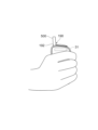
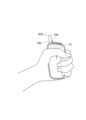
- FIG. 3 is a diagram showing an example of a state in which the generating device is held with the right hand.
- FIG. 3 is a diagram showing an example of a state in which the generating device is held in the left hand.
- FIG. 3 is a diagram showing an example of information stored in a storage unit. It is a figure which shows an example of the information which the output part output to the portable terminal. It is a figure which shows an example of the information which the output part output to the portable terminal. It is a flowchart which shows an example of the heating control process performed by a control part. It is a flowchart which shows an example of the on-off control process performed by a control part. It is a figure which shows an example of the information which the output part output to the portable terminal. 11 is a diagram illustrating an example of a correspondence relationship between sensors and whether or not output to a portable terminal is required. FIG.
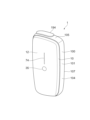
- FIG. 1 is an example of a view of the aerosol generation device 1 viewed diagonally from above.
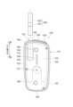
- FIG. 2 is an example of a view of the aerosol generation device 1 viewed diagonally from below.
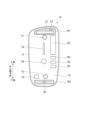
- FIG. 3 is an example of a front view of the main body 100 with the cover 10 removed.
- FIG. 4 is an example of a view of the cover 10 viewed from the rear side.
- FIG. 5 is an example of a diagram schematically showing a configuration example of the main body 100.
- FIG. 6 is an example of a diagram schematically showing the configuration of the cover 10. As shown in FIG.
- the aerosol generation device 1 (hereinafter sometimes simply referred to as the "generation device 1") includes a heating section that heats a base material 500 (hereinafter sometimes simply referred to as the "base material 500") including an aerosol source. 170, and a cover 10 that is removable from the main body 100.
- the main body 100 has a substantially rectangular parallelepiped-shaped housing 101 that accommodates a heating section 170 and the like.
- the cover 10 covers one side of the housing 101.
- the side to which the cover 10 is attached is the front side 102, the left side when viewed from the front 102 side is the left side 103, the right side is the right side 104, and the upper side is the top side. 105, the lower surface is referred to as a bottom surface 106.
- a surface connected to the left side 103, right side 104, top surface 105, and bottom surface 106, and which is different from the front surface 102 is referred to as a back surface 107.
- the cover 10 covers the front surface 102 of the housing 101, and the left side surface 103, right side surface 104, top surface 105, bottom surface 106, and back surface 107 are exposed to the outside with the cover 10 attached.
- the main body 100 includes a power supply section 110, a sensor section 120, a notification section 130, a storage section 140, a communication section 150, a control section 160, a heating section 170, and a heat insulation section 180. , and a holding section 190.
- the power supply section 110 , the sensor section 120 , the notification section 130 , the storage section 140 , the communication section 150 , the control section 160 , the heating section 170 , and the heat insulation section 180 are housed in the housing 101 .
- the main body 100 also includes a shutter 194 (see FIG. 1) that is disposed on the top surface 105 and can be slid along the top surface 105. Each component will be explained in order below.
- the power supply unit 110 includes a battery 111 that stores power and a power supply unit 112 that supplies power.
- An example of the battery 111 is a rechargeable battery such as a lithium ion secondary battery.
- the battery 111 may be charged by being connected to an external power source via a cable or the like connected to a USB (Universal Serial Bus) terminal 113. Further, the battery 111 may be charged without being connected to a power transmitting device using wireless power transmission technology. Alternatively, only the battery 111 may be removed from the main body 100, or may be replaced with a new battery 111.
- the power supply unit 112 supplies power to each component of the main body 100 based on control by the control unit 160. Further, the power supply unit 112 supplies power to the cover 10 .
- the power supply unit 112 supplies power to the cover 10 by, for example, non-contact power transmission.
- An example of contactless power transmission is power transmission using short-range wireless communication. This makes it possible to supply power to the cover 10 with a simple configuration.
- the sensor unit 120 detects various information regarding the main body 100. The sensor section 120 then outputs the detected information to the control section 160.
- the sensor section 120 is configured with a pressure sensor, a flow rate sensor, or a temperature sensor such as a microphone capacitor. When the sensor unit 120 detects a numerical value associated with suction by the user, it outputs information indicating that suction has been performed by the user to the control unit 160.
- the sensor unit 120 is configured with an input device such as a button or a switch that receives information input from the user.
- the sensor unit 120 may include a button for instructing start/stop of aerosol generation.
- the sensor unit 120 then outputs the information input by the user to the control unit 160.
- the sensor unit 120 has an operation button 121 that instructs to start generating aerosol. As shown in FIG. 3, the operation button 121 is provided so as to be exposed from the front surface 102 of the housing 101.
- the notification unit 130 notifies the user of information.
- the notification unit 130 is configured with a light emitting device such as an LED (Light Emitting Diode).
- the notification unit 130 emits light in different light emission patterns when the battery 111 of the power supply unit 110 requires charging, when the battery 111 is being charged, when an abnormality occurs in the main body 100, etc. do.
- the light emission pattern here is a concept that includes color, timing of turning on/off, and the like.
- the notification unit 130 may be configured with a display device that displays an image, a sound output device that outputs sound, a vibration device that vibrates, etc. together with or in place of the light emitting device.
- a display window 108 is formed on the front surface 102 of the housing 101 and transmits light emitted by a light emitting device such as an LED as an example of the notification section 130.
- the light emitting device is provided at the rear of the display window 108. There is.
- the storage unit 140 stores various information for the operation of the generation device 1.
- the storage unit 140 is configured by, for example, a nonvolatile storage medium such as a flash memory.
- An example of the information stored in the storage unit 140 is information regarding the OS (Operating System) of the generation device 1, such as control details of various components by the control unit 160.
- Another example of information stored in the storage unit 140 is information related to suction by the user, such as the number of suctions, the time of suction, and the cumulative suction time.
- the communication unit 150 is a communication interface for transmitting and receiving information between the generation device 1 and other devices.
- the communication unit 150 performs communication based on any wired or wireless communication standard.
- a communication standard for example, wireless LAN (Local Area Network), wired LAN, Wi-Fi (registered trademark), Bluetooth (registered trademark), etc. may be adopted.
- the communication unit 150 transmits information regarding suction by the user to another device (for example, a portable terminal 600 described below) to display the information regarding suction by the user.
- the communication unit 150 receives new OS information from a server in order to update the OS information stored in the storage unit 140.
- the control unit 160 functions as an arithmetic processing device and a control device, and controls overall operations within the generation device 1 according to various programs.
- the control unit 160 is realized by, for example, an electronic circuit such as a CPU (Central Processing Unit) and a microprocessor.
- the control unit 160 may include a ROM (Read Only Memory) that stores programs to be used, calculation parameters, etc., and a RAM (Random Access Memory) that temporarily stores parameters that change as appropriate.
- the generation device 1 executes various processes based on control by the control unit 160.
- the heating unit 170 atomizes the aerosol source to generate aerosol by heating the aerosol source.
- the heating section 170 is made of any material such as metal or polyimide.
- the heating unit 170 is configured in a film shape and is arranged to cover the outer periphery of the holding unit 190. Then, when the heating section 170 generates heat, the aerosol source included in the base material 500 is heated from the outer periphery of the base material 500 and atomized, thereby generating an aerosol.
- the heating unit 170 generates heat when supplied with power from the power supply unit 110, and heats the base material 500. When the temperature of the base material 500 heated by the heating unit 170 reaches a predetermined temperature, suction by the user becomes possible. Thereafter, when the sensor unit 120 detects that a predetermined user input has been performed, the power supply may be stopped.
- the heat insulating section 180 prevents heat transfer from the heating section 170 to other components of the generation device 1 .
- the heat insulating section 180 is arranged to cover at least the outer periphery of the heating section 170.
- the heat insulating section 180 is made of a vacuum heat insulating material, an airgel heat insulating material, or the like.
- Vacuum insulation material is an insulation material that reduces heat conduction by gas to as close to zero as possible by wrapping glass wool, silica (silicon powder), etc. in a resin film and creating a high vacuum state. be.
- the holding part 190 has a columnar internal space 191 provided inside the housing 101 and an opening 192 formed in the upper surface 105 of the housing 101 to communicate the internal space 191 to the outside.
- the internal space 191 is a cylindrical body having a bottom portion 193 as a bottom surface.
- the holding part 190 is configured such that its inner diameter is smaller than the outer diameter of the base material 500 in at least a portion of the height direction of the cylindrical body, and holds the base material 500 inserted into the internal space 191 from the opening 192 around the outer periphery.
- the base material 500 can be held by being compressed.
- the holding portion 190 also has the function of defining an air flow path through the base material 500.
- An air inlet hole which is an entrance for air into the flow path, is arranged, for example, at the bottom portion 193.
- the air outlet hole which is the outlet of the air from the flow path, is the opening 192.
- the opening 192 is exposed by sliding the shutter 194 to the open position and hidden by sliding the shutter 194 to the closed position.
- the shutter 194 has a magnet on its back surface.
- a magnetic sensor included in the sensor section 120 is attached to the upper surface 105 of the housing 101 within the movable range of the shutter 194.
- the magnetic sensor is a Hall IC composed of a Hall element, an operational amplifier, etc., and outputs a voltage according to the strength of the magnetic field that crosses the Hall element.
- control unit 160 detects opening and closing of shutter 194 from changes in voltage output from the magnetic sensor as shutter 194 slides.
- the base material 500 is a stick-shaped member.
- the base material 500 includes a base material part 501 and a mouthpiece part 502.
- Base portion 501 includes an aerosol source.
- the aerosol source is heated and atomized to produce an aerosol.
- the aerosol source may be derived from tobacco, such as a processed product formed from shredded tobacco or tobacco raw material into granules, sheets, or powder. Aerosol sources may also include non-tobacco sources made from plants other than tobacco, such as mint and herbs. As an example, the aerosol source may include a fragrance ingredient such as menthol. If the generating device 1 is a medical inhaler, the aerosol source may contain a medicament for inhalation by the patient.
- the aerosol source is not limited to solids, and may be, for example, polyhydric alcohols such as glycerin and propylene glycol, and liquids such as water. At least a portion of the base material part 501 is accommodated in the internal space 191 of the holding part 190 while the base material 500 is held by the holding part 190.
- the suction part 502 is a member that is held in the user's mouth during suction. At least a portion of the mouthpiece 502 protrudes from the opening 192 when the base material 500 is held by the holding part 190. Then, when the user holds the suction port 502 protruding from the opening 192 and sucks it, air flows into the holding part 190 from an air inflow hole (not shown). The inflowing air passes through the internal space 191 of the holding part 190, that is, passes through the base material part 501, and reaches the user's mouth together with the aerosol generated from the base material part 501.
- the main body 100 is provided so as to be exposed from the front surface 102 of the housing 101, and has two magnets used for connection with the cover 10, an upper magnet 195 and a lower magnet 196.
- the upper magnet 195 and the lower magnet 196 have a circular cylindrical shape when viewed from the front.
- the centers of the circles of the upper magnet 195 and the lower magnet 196 are arranged in the direction of the center line of the base material 500 by the holding part 190 (hereinafter sometimes simply referred to as the "center line direction"), and the upper magnet 195 and the lower magnet 196 are A magnet 195 is provided at the top of the main body 100, and a lower magnet 196 is provided at the bottom of the main body 100.
- the main body 100 has an operation button 121 provided at the center in the center line direction so as to be exposed from the front surface 102 of the housing 101.
- the operation button 121 is arranged between the upper magnet 195 and the lower magnet 196.
- the main body 100 has a display window 108 above the operation button 121 and between the upper magnet 195 and the operation button 121 that allows light from a light emitting device such as an LED to pass through to a display window 74 (described later) of the cover 10.
- the display window 108 is a window provided at a position corresponding to the position of the light emitting device arranged in the housing 101 of the main body 100, and allows light from the light emitting device to pass through to the display window 74 of the cover 10. This allows the user to visually recognize the light from the outer surface of the cover 10.
- the main body 100 has a magnetic sensor 122.
- the magnetic sensor 122 detects magnetic force based on a magnetic field applied from a magnet 75 of the cover 10, which will be described later.
- the magnetic sensor 122 is preferably a Hall sensor configured using a Hall element. Thereby, attachment of the cover 10 to the main body 100 can be detected.
- the cover 10 includes a cover body 11, a power supply section 20, a sensor section 30, a storage section 40, a communication section 50, and a control section 60.
- the cover main body 11 is formed into a plate shape from a light-transmitting member, covers the front surface 102 of the housing 101 of the main body 100, and has steps formed on the left side 103, right side 104, top surface 105, and bottom surface 106 of the housing 101. It is molded so that it does not occur. Thereby, the cover 10 forms an appearance that is integrated with the left side 103, right side 104, top surface 105, and bottom surface 106 of the housing 101, and has a decorative function. Further, the cover 10 has a function of suppressing the propagation of heat emitted from the main body 100.
- the power supply section 20, the sensor section 30, the storage section 40, the communication section 50, and the control section 60 are attached to the cover body 11.
- the power supply section 20 includes a battery 21 that stores power, a power supply section 22 that supplies power to each component of the cover 10, and a power reception section 23 that receives power from the power supply section 112 of the power supply section 110 of the main body 100.
- the battery 21 can be exemplified as a rechargeable battery such as a lithium ion secondary battery formed in a film shape, for example.
- the battery 21 is charged by the power supplied to the cover 10 from the power supply section 112 of the power supply section 110 of the main body 100.
- the power supply unit 22 supplies power from the battery 21 to each component of the cover 10. Further, the power feeding unit 22 supplies the power received by the power receiving unit 23 to each component of the cover 10 . As a result, each component of the cover 10 including the sensor section 30 can be operated by the power supplied from the main body 100 to the cover 10.
- the power receiving unit 23 includes an NFC (Near Field Communication) reader/writer module, an NFC antenna, etc. It consists of:
- the sensor unit 30 includes an ambient air sensor that detects information about the air surrounding the generation device 1 .
- Air information can be exemplified by temperature and humidity. That is, the sensor unit 30 includes, as an example of an ambient air sensor, a temperature sensor that can detect the temperature (for example, room temperature) around the generation device 1 and a humidity sensor that can detect the surrounding humidity.
- the air information may be atmospheric pressure, and the sensor unit 30 may have an atmospheric pressure sensor capable of detecting the atmospheric pressure around the generation device 1 as an example of an ambient air sensor.
- the sensor unit 30 may include a vital sensor that detects the user's biological information.
- the vital sensor can be exemplified as a sensor capable of detecting any one of the user's body temperature, heart rate, pulse rate, blood oxygen saturation, blood flow, and COHb (carbohemoglobin).
- An example of a sensor that detects the user's body temperature is a sensor that converts infrared rays emitted from the forehead or the like into body temperature.
- a sensor that detects at least one of heart rate, pulse rate, blood oxygen saturation, blood flow, and COHb includes a light-emitting element that emits light onto the human body, and a sensor that transmits the light emitted by the light-emitting element through the user's body.
- An example of an optical sensor includes a light-receiving element that receives light, and outputs information regarding the light received by the light-receiving element.
- the light emitting element is a light source, and is realized by, for example, an LED or the like.
- the light receiving element is realized by, for example, a photodiode or the like.
- the light received by the light receiving element is, for example, reflected light from a human body. This reflected light includes light scattered and reflected within the human body (ie, scattered light).
- the vital sensor may be a sensor that can detect the alcohol concentration in the user's breath.
- the sensor unit 30 may include a distance sensor capable of detecting the distance between the generation device 1 and the target object, or a color sensor capable of detecting the color of the target object.
- the sensor unit 30 includes a touch sensor 35 that detects that the user is touching the cover 10. Since suction can be started by the user touching the touch sensor 35, FIG. 1 and the like show an example in which the touch sensor 35 is disposed at the center of the generating device 1 in the center line direction. However, the position of the touch sensor 35 is not limited to the position shown in FIG. 1 and the like.
- a sensor that detects external information may be referred to as an "external sensor 31.”
- the external sensor 31 is a general term for sensors that detect external environment information of the generation device 1, such as a temperature sensor, humidity sensor, and atmospheric pressure sensor, a vital sensor that detects biometric information of the user, a distance sensor, and a color sensor.
- the external information includes biological information such as body temperature, heart rate, pulse rate, blood oxygen saturation, blood flow, COHb, and alcohol concentration, and external environmental information such as temperature and humidity.
- the storage unit 40 stores various information for the operation of the cover 10.
- the storage unit 40 is composed of, for example, a nonvolatile storage medium such as a flash memory.
- An example of the information stored in the storage unit 40 is information related to the OS (Operating System) of the cover 10, such as control details of various components by the control unit 60.
- the storage unit 40 stores information acquired from the sensor unit 30.
- the storage unit 40 also stores a predetermined temperature range and a predetermined humidity range, which will be described later.
- the communication unit 50 is a communication interface for transmitting and receiving information between the cover 10 and an external device other than the cover 10.
- the communication unit 50 performs communication based on any wired or wireless communication standard.
- a communication standard for example, wireless LAN (Local Area Network), wired LAN, Wi-Fi (registered trademark), Bluetooth (registered trademark), etc. may be adopted.
- the external device is a device other than the main body 100 or the generation device 1, and the device other than the generation device 1 is a multifunction mobile phone (so-called “smartphone") owned by the user.Hereinafter, may be referred to as a "mobile phone”. ), etc., or a server (not shown).
- the portable terminal 600 may be a tablet terminal, a tablet PC, a personal digital assistant (PDA), or a notebook PC.
- the communication unit 50 transmits information detected by the sensor unit 30 to a mobile phone. Furthermore, the communication unit 50 receives new OS information from the server in order to update the OS information stored in the storage unit 40.
- the communication unit 50 may communicate with the main body 100 by, for example, short-range wireless communication.
- short-range wireless communication As described above, power is supplied from the main body 100 to the cover 10 by short-range wireless communication, and the communication unit 50 communicates with the main body 100 by short-range wireless communication, so that the main body 100 and Communication and power transmission with the cover 10 can be efficiently realized, and the configurations of the main body 100 and the cover 10 can be simplified.
- the communication unit 50 is connected to the power receiving unit. This can be realized using the same NFC reader/writer module, NFC antenna, etc. as in No. 23.
- the communication unit 50 may communicate with the main body 100 via this power supply interface.
- the control unit 60 functions as an arithmetic processing device and a control device, and controls overall operations within the cover 10 according to various programs.
- the control unit 60 is realized by, for example, an electronic circuit such as a CPU and a microprocessor.
- the control unit 60 may include a ROM that stores programs to be used, calculation parameters, etc., and a RAM that temporarily stores parameters that change as appropriate.
- the cover 10 executes various processes based on control by the control unit 60.
- the control unit 60 controls power supply from the power supply unit 20 to other components, charging of the power supply unit 20, detection by the sensor unit 30, storage and reading of information by the storage unit 40, and transmission and reception of information by the communication unit 50. This is an example of the processing performed.
- Other processes executed by the cover 10, such as inputting information to each component and processing based on information output from each component, are also controlled by the control unit 60.
- control unit 60 transmits and receives data to and from the control unit 160 of the main body 100 via the communication unit 50.
- the control unit 60 transmits the detected value of the sensor unit 30 to the control unit 160 of the main body 100.
- the control unit 60 receives from the control unit 160 of the main body 100, for example, information that heating of the heating unit 170 has started or that heating has stopped.
- the cover 10 has an upper magnet 71 and a lower magnet 72 on the back surface 13 of the cover main body 11, which is the surface on the main body 100 side.
- the upper magnet 71 and the lower magnet 72 have a circular cylindrical shape when viewed from the rear side, and are provided at positions corresponding to the upper magnet 195 and the lower magnet 196 provided on the main body 100, respectively.
- the upper magnet 71 and the lower magnet 72 are arranged in the direction of the center line, and the upper magnet 71 is provided on the upper part of the cover 10 and the lower magnet 72 is provided on the lower part of the cover 10.
- the cover 10 is attached to the main body 100 by the attraction between the magnets.
- the cover 10 is not limited to being attached to the main body 100 by the attraction force between magnets.
- the cover 10 and the main body 100 may have a structure in which they physically fit together.
- the physical fitting structure is a structure in which a fitting claw provided on one member of the cover 10 or the main body 100 (for example, the cover 10) is fitted into a hole or a recess formed in the other member (for example, the main body 100). It can be exemplified that
- the touch sensor 35 described above is provided between the upper magnet 71 and the lower magnet 72, in other words, at the center of the cover 10 in the center line direction.
- the position of the touch sensor 35 is not limited.
- the touch sensors 35 may be provided at multiple locations.
- a display window 74 is formed in the cover body 11 between the upper magnet 71 and the lower magnet 72 and above the touch sensor 35.
- the display window 74 is provided at a position corresponding to the display window 108 provided in the main body 100.
- the cover body 11 is made of a material that transmits light. Thereby, the cover 10 transmits light emitted from the light emitting element provided in the main body 100 to the front surface 12 of the cover main body 11.
- the cover 10 has a magnet 75 on the left side in FIG. 4 of the line connecting the upper magnet 71 and the lower magnet 72.
- the magnet 75 is provided at a position corresponding to the magnetic sensor 122 provided on the main body 100, and attachment of the cover 10 to the main body 100 is detected by the magnetic sensor 122 provided on the main body 100.
- the external sensor 31 of the sensor unit 30 is located at both ends of the cover 10 in the center line direction, in other words, the first region R1 is located above the upper magnet 71 and below the lower magnet 72, as shown in FIG. Preferably, it is provided in either of the second regions R2.
- the external sensor 31 is a light sensor
- a light emitting element emits light to a finger or the like placed in front of the front surface 12 of the cover body 11, and the light emitted by the light emitting element is received via the finger or the like. Therefore, if dirt adheres to the area through which the light passes, it will be difficult to detect with high accuracy.
- FIG. 7 is a diagram showing an example of a state in which the generation device 1 is held with the right hand.
- FIG. 8 is a diagram showing an example of a state in which the generating device 1 is held in the left hand.
- FIG. 4 shows an example in which the external sensor 31 is provided in the first region R1.
- the external sensor 31 is provided in the first region R1.
- the hand is on the side (upper side) of the opening 192 of the holding part 190 than the upper magnet 71. Since the area where the external sensor 31 is arranged is difficult to be touched by hand.
- the external sensor 31 is arranged in an area that is difficult to touch by the user, dirt is difficult to adhere to the front surface 12 of the cover 10, so that highly accurate detection is possible.
- the external sensor 31 may be provided in the second region R2 below the lower magnet 72. This is because even in the second region R2, even if the generating device 1 is held with the right hand or the left hand when suctioning with the generating device 1, the position corresponds to the little finger, and it is difficult for the user to apply a load to the second region R2.
- the external sensor 31 is a sensor other than an optical sensor (for example, a temperature sensor or a humidity sensor), by arranging it in the first region R1 or the second region R2, it is possible to make it difficult for the user to apply a load. Therefore, the external sensor 31 can be made less likely to fail.
- an optical sensor for example, a temperature sensor or a humidity sensor
- the control unit 60 includes an output unit 61 (see FIG. 6) that outputs information detected by the external sensor 31 of the sensor unit 30 to an external device via the communication unit 50.
- the output unit 61 outputs, for example, the temperature and humidity detected by the temperature sensor and humidity sensor, which are examples of the external sensor 31, to the portable terminal 600. This allows the user to check information about the surrounding air using the portable terminal 600.
- FIG. 9 is a diagram showing an example of information stored in the storage unit 40.
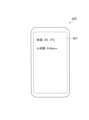
- 10 and 11 are diagrams showing examples of information outputted by the output unit 61 to the portable terminal 600.
- the output unit 61 outputs to the portable terminal 600 that the temperature or humidity is appropriate for storing the base material 500 based on the temperature or humidity detected by the temperature sensor or the humidity sensor.
- the storage unit 40 stores a predetermined temperature range (hereinafter sometimes referred to as a "predetermined temperature range”) as a temperature range suitable for storing the base material 500. put. Then, when the temperature detected by the temperature sensor is within the predetermined temperature range, the output unit 61 outputs to the portable terminal 600 the temperature detected by the temperature sensor as well as the fact that the temperature is appropriate for storage. As a result, as shown in FIG. 10, the display unit 601 of the portable terminal 600 displays that the temperature is appropriate for storage.
- An example of the predetermined temperature range is 10°C to 28°C, preferably 17°C to 21°C.
- the storage unit 40 stores a predetermined humidity range (hereinafter sometimes referred to as a "predetermined humidity range”) as a humidity range suitable for storing the base material 500. put. Then, when the humidity detected by the humidity sensor is within the predetermined humidity range, the output unit 61 outputs to the portable terminal 600 the humidity detected by the humidity sensor and a message that the humidity is appropriate for storage. As a result, as shown in FIG. 10, the display unit 601 of the portable terminal 600 displays that the humidity is appropriate for storage.
- An example of the predetermined humidity range is 66% to 74%, preferably 68% to 72%.
- the storage unit 40 stores a predetermined temperature range as a temperature range suitable for storing the base material 500, and also stores a predetermined humidity range as a humidity range suitable for storage. Then, when the temperature detected by the temperature sensor is within a predetermined temperature range and the humidity detected by the humidity sensor is within a predetermined humidity range, the output unit 61 outputs the temperature and humidity detected by the temperature sensor. It is preferable to output to the portable terminal 600, along with the detected humidity, information that the temperature and humidity are appropriate for storage.
- the output unit 61 outputs information detected by the vital sensor included in the sensor unit 30 to the portable terminal 600.
- the vital sensor detects at least one of the user's body temperature, heart rate, pulse rate, blood oxygen saturation, blood flow, COHb, and alcohol concentration
- the output unit 61 detects the user's body temperature, heart rate, pulse rate, blood oxygen saturation, blood flow, COHb, and alcohol concentration.
- the body temperature, heart rate, pulse rate, blood oxygen saturation, blood flow, COHb, and/or alcohol concentration are output to the portable terminal 600.
- the sensor unit 30 has a vital sensor that detects the user's body temperature and heart rate, and the output unit 61 outputs the body temperature and heart rate detected by the vital sensor to a portable terminal 600, and the output unit 61 outputs the body temperature and heart rate detected by the vital sensor to a portable terminal 600.
- a mode is shown in which body temperature and heart rate are displayed on the display unit 601 of the terminal 600. By displaying in this manner, the user can check information regarding his or her own body on the portable terminal 600.
- the control unit 160 of the main body 100 allows generation of aerosol when the cover 10 is attached. That is, the control unit 160 allows the heating unit 170 to heat when the cover 10 is attached to the main body 100. In other words, the cover 10 allows the heating unit 170 to be heated by the main body 100 by being attached to the main body 100. As described above, the control unit 160 is able to determine whether the cover 10 is attached to the main body 100 using the output value of the Hall sensor.
- control section 160 of the main body 100 may control the heating of the heating section 170 based on the output of the sensor section 30 of the cover 10. Thereby, it becomes possible to operate the generation device 1 appropriately according to the user's condition.
- the quality of the suction experience (for example, smoking experience) that the user can experience by using the generating device 1 may depend on the user's own physical condition. Therefore, even if the aerosol source and flavor source match the user's preferences, if the user is not feeling well, the user may not be able to obtain a high-quality suction experience. In this way, it is preferable to generate aerosol in the generation device 1 even though the user cannot obtain a high-quality suction experience, as this will lead to waste of the aerosol source and the flavor source. do not have.
- the generating device 1 it may also be possible to disallow heating of the
- the predetermined range of the detection value of the vital sensor that permits heating of the heating unit 170 may be referred to as a "predetermined permission range.”
- the predetermined permitted range can be 38° C. or lower.
- the predetermined permitted range can be exemplified as 65 to 85 bpm (beats/min).
- the vital sensor is a sensor capable of detecting the user's pulse rate
- the predetermined permission range can be exemplified as 65 to 100 bpm (times/min).
- the vital sensor is a sensor capable of detecting blood oxygen saturation
- the predetermined permission range can be exemplified as 96% or more.
- the predetermined permitted range can be exemplified as 20 to 60 ml/min/100 g. Further, when the vital sensor is a sensor capable of detecting COHb, the predetermined permission range can be exemplified as less than 2%. Further, when the vital sensor is an alcohol sensor capable of detecting the alcohol concentration in exhaled breath, the predetermined permitted range can be exemplified as 0.20 mg or less.
- the storage unit 140 stores a predetermined permission range for each biometric information.
- the control unit 160 of the main body 100 may acquire the detection value of the vital sensor from the cover 10 and may not permit heating of the heating unit 170 if the detection value is outside a predetermined permitted range.
- FIG. 12 is a flowchart illustrating an example of the heating control process performed by the control unit 160.
- the control unit 160 repeatedly executes this process at preset fixed time intervals (for example, 1 millisecond).
- the control unit 160 determines whether there is a heating instruction (S1201).
- An example of the heating instruction can be that the touch sensor 35 is continuously touched for a predetermined period of time (for example, 3 seconds). If there is a heating instruction (YES in S1201), the control unit 160 determines whether the cover 10 is attached (S1202). This process is a process for determining whether the magnetic sensor 122 has detected magnetic force.
- the control unit 160 determines whether the value detected by the vital sensor is within a predetermined permissible range (S1203). Then, if it is within the predetermined permission range (YES in S1203), the control unit 160 starts heating the heating unit 170 (S1204). Further, the control unit 160 transmits to the control unit 60 of the cover 10 that the heating unit 170 has started heating. Then, the control unit 160 heats the heating unit 170 according to a control sequence that is stored in the storage unit 140 of the main body 100 and defines a temporal change in the target temperature of the heating unit 170 when heating the heating unit 170, and then heats the heating unit 170. stop. After stopping the heating of the heating unit 170, the control unit 160 transmits to the control unit 60 of the cover 10 that the heating of the heating unit 170 has been stopped.
- control unit 160 does not start heating the heating unit 170 (S1205).
- control unit 160 of the main body 100 allows the heating unit 170 to heat when the detection value of the vital sensor is within the predetermined permission range, thereby allowing the user to have a high-quality suction experience and reducing the aerosol source, etc. You can prevent this from leading to waste.
- control unit 160 may permit heating of the heating unit 170 without being based on the detected value of the vital sensor.
- control unit 160 may perform heating without making the determination in S1203 of FIG. 12 when the cover 10 is attached (YES in S1202). It is only necessary to start heating the section 170.
- control unit 160 may allow the heating unit 170 to heat even if the cover 10 is not attached.
- control unit 160 may control the detection value of the vital sensor within the predetermined permission range without making the determination in S1202 of FIG. If so (YES in S1203), heating of the heating unit 170 may be started.
- the switch of the touch sensor 35 may be off when the heating section 170 of the main body 100 is heating. Then, when the heating section 170 of the main body 100 is heating, the touch sensor 35 is turned off, and the touch sensor 35 no longer outputs the on signal, so that the external sensor 31 may be turned off. In this way, it is possible to save energy by turning off the touch sensor 35 and the external sensor 31 while the heating section 170 of the main body 100 is heating.
- FIG. 13 is a flowchart illustrating an example of the on/off control process performed by the control unit 60.
- the control unit 60 is activated, for example, when the touch sensor 35 detects that the user is touching the cover 10, and executes the process illustrated in FIG. 13 at preset intervals (for example, 1 millisecond). Execute repeatedly.
- control unit 60 transmits to the control unit 160 of the main body 100 that the control unit 60 has been activated (S1301). Then, the control unit 60 turns on the switch of the external sensor 31 (S1302), and transmits the detected value of the external sensor 31 to the control unit 160 of the main body 100 (S1303). After that, the control unit 60 determines whether the heating unit 170 of the main body 100 has started heating (S1304). This is a process in which the control unit 60 determines whether or not it has received a notification from the control unit 160 of the main body 100 that heating of the heating unit 170 has started.
- the control unit 60 When heating is started (YES in S1304), the control unit 60 turns off the switch of the touch sensor 35 (S1305). When the touch sensor 35 is off, the touch sensor 35 no longer outputs an on signal, so the control unit 60 turns off the external sensor 31 (S1306). After that, the control unit 60 determines whether the heating unit 170 of the main body 100 has stopped heating (S1307). If the heating has not been stopped (NO in S1307), the control unit 60 waits until the heating is stopped.
- the control unit 60 When heating is stopped (YES in S1307), the control unit 60 turns on the switch of the touch sensor 35 (S1308). After that, the control unit 60 determines whether the touch sensor 35 detects that the user is touching the cover 10 (S1309). If the touch sensor 35 detects the touch (YES in S1309), the control unit 60 performs the processes from S1302 onwards. On the other hand, if the touch sensor 35 does not detect it (NO in S1309), the control unit 60 transmits to the control unit 160 of the main body 100 that the control unit 60 will turn off the power (S1310), and turns off the power. (S1311). On the other hand, if heating has not started (NO in S1304), the control unit 60 performs the processes from S1309 onwards.
- FIG. 14 is a diagram showing an example of information outputted by the output unit 61 to the portable terminal 600.
- the output unit 61 of the control unit 60 outputs to the portable terminal 600 that the external sensor 31 has failed.
- the display unit 601 of the portable terminal 600 displays that the humidity sensor has failed. Examples of failures in the external sensor 31 include disconnections and short circuits.
- the output unit 61 may output to the portable terminal 600 depending on the type of the external sensor 31. For example, the output unit 61 outputs to the portable terminal 600 when the vital sensor, temperature sensor, and humidity sensor are out of order, and does not output to the portable terminal 600 when the atmospheric pressure sensor, distance sensor, and color sensor are out of order. You can do it like this.
- the reason why the vital sensor is output to the portable terminal 600 when the vital sensor fails is because heating of the heating unit 170 is not permitted unless the detected value of the vital sensor is within a predetermined permitted range. This is because it may become impossible to inhale aerosols. Furthermore, the reason why the temperature sensor and the humidity sensor are output to the portable terminal 600 when they fail is because it is not possible to notify the user that the temperature and humidity are within the predetermined range.
- the types of external sensors 31 that output to the portable terminal 600 in the event of failure and the types of external sensors 31 that do not output to the portable terminal 600 even if they fail are not particularly limited. You can set it arbitrarily.
- FIG. 15 is a diagram illustrating an example of the correspondence between sensors and whether output to the portable terminal 600 is necessary.
- the storage unit 40 stores, for each external sensor 31 included in the sensor unit 30, whether or not to output to the portable terminal 600 that the external sensor 31 has failed. In the example shown in FIG. 15, the storage unit 40 needs to output to the portable terminal 600 when the vital sensor, temperature sensor, and humidity sensor are out of order, and when the air pressure sensor, distance sensor, and color sensor are out of order. It is stored that there is no need to output to the portable terminal 600.
- the output unit 61 outputs the portable terminal 600 if it is stored in the storage unit 40 that it is necessary to notify when the sensor fails. If the storage unit 40 stores that it is unnecessary to output to the sensor and notify when the sensor fails, it is preferable not to output to the portable terminal 600.
- the output unit 61 when a vital sensor malfunctions, if it is stored that it is necessary to notify that the vital sensor has failed, the output unit 61 outputs a message indicating that the vital sensor has failed. is output to the portable terminal 600. On the other hand, as shown in FIG. 15, for example, if it is stored that there is no need to notify that the atmospheric pressure sensor has failed, the output unit 61 notifies the portable terminal 600 that the atmospheric pressure sensor has failed. Prevent it from being output.
- the cover 10 is a cover 10 that is attached to the main body 100 that has the heating section 170 that heats the base material 500 containing the aerosol source.
- the cover 10 includes an external sensor 31 as an example of a sensor that detects internal information related to the state of the main body 100 (for example, the temperature of the heating section 170) and external information other than the internal information related to the state of the cover 10. It includes a communication unit 50 that performs communication, and an output unit 61 that outputs external information detected by the external sensor 31 to an external device other than the cover 10 (for example, a portable terminal 600) via the communication unit 50.
- the user can read biological information such as body temperature, heart rate, pulse rate, blood oxygen saturation, blood flow, COHb, alcohol concentration, etc., and external environmental information such as temperature and humidity. can be confirmed using, for example, the portable terminal 600, thereby increasing user convenience.
- biological information such as body temperature, heart rate, pulse rate, blood oxygen saturation, blood flow, COHb, alcohol concentration, etc.
- external environmental information such as temperature and humidity.
- the external sensor 31 is preferably provided at either end in the centerline direction of the columnar holding portion 190 formed on the main body 100 so as to accommodate a part of the base material 500. This makes it difficult for the user to apply a load to the external sensor 31, making it difficult for the external sensor 31 to fail.
- the cover 10 further includes an upper magnet 71 and a lower magnet 72 as an example of a plurality of connecting parts connected to the main body 100, and the external sensor 31 is attached to the main body 100 so as to accommodate a part of the base material 500. It is preferable that the opening 192 of the holding part 190 be provided closer to the opening 192 of the holding part 190 than the upper magnet 71 and the lower magnet 72 in the direction of the center line of the formed columnar holding part 190 .
- the area closer to the opening 192 (upper side) than the upper magnet 71 is an area that is difficult to touch by the user even if the generating device 1 is held with the right or left hand during suction, so dirt is unlikely to adhere to the front surface 12 of the cover 10. Therefore, highly accurate detection is possible.
- the external sensor 31 detects temperature or humidity, and the output unit 61 outputs an external device (for example, it is output to a portable terminal 600).
- the cover 10 configured in this way, the user can confirm the appropriate place to store the base material 500 using, for example, the portable terminal 600, thereby increasing the user's convenience. Moreover, it becomes possible to store the base material 500 in an appropriate place.
- the output unit 61 outputs the fact that the external sensor 31 has failed to an external device (for example, the portable terminal 600). This makes it possible to notify the user that the external sensor 31 has failed.
- the cover 10 has a plurality of sensors (for example, a temperature sensor, a vital sensor, etc.), and further includes a storage unit 40 that stores, for each sensor, whether or not it is necessary to notify when the sensor breaks down. .
- the output unit 61 outputs an external device (e.g. If it is stored in the storage unit 40 that it is unnecessary to output to the portable terminal 600) and notify when the sensor has failed, it is not output to the external device.
- an external device e.g. If it is stored in the storage unit 40 that it is unnecessary to output to the portable terminal 600
- notify when the sensor has failed it is not output to the external device.
- compared to a configuration in which failures of all sensors are output to an external device it is possible to achieve energy savings.
- Wi-Fi (registered trademark) and Bluetooth (registered trademark) use overlapping frequency bands, so if Wi-Fi (registered trademark) and Bluetooth (registered trademark) are used at the same time, their radio waves may interfere with each other. This is to prevent the communication speed from slowing down or being disconnected.
- one of the two antennas is provided at one end of both ends in the center line direction, and the other antenna is provided at the other end of both ends in the center line direction.
- the first antenna 51 for Wi-Fi (registered trademark) is provided in the first region R1 above the upper magnet 71
- the second antenna 52 for Bluetooth registered trademark
- it is provided in the second region R2 below the lower magnet 72.
- the communication unit 50 of the cover 10 can communicate using multiple wireless communications (Wi-Fi (registered trademark), Bluetooth (registered trademark)) that have different communication distances.
- a first antenna 51 (an example of one antenna) among the plurality of antennas used for each of the plurality of wireless communications is formed in the main body 100 so as to accommodate a part of the base material 500 holding the aerosol source.
- the second antenna 52 (an example of another antenna) is provided at the other end of the columnar holding portion 190 in the center line direction. Thereby, it is possible to prevent the communication speed from slowing down or the connection from being disconnected due to interference between radio waves caused by using a plurality of wireless communications at the same time.
- the cover 10 configured as described above has the battery 21, so even if the cover 10 is not attached to the main body 100, the external sensor 31 can detect temperature, humidity, biological information, etc. It can be detected and output to the portable terminal 600. Therefore, there is no need for the user to carry the main body 100 when searching for an appropriate place to store the base material 500.
- the amount of power per unit time that can be supplied from the power supply unit 112 of the main body 100 to the cover 10 by contactless power transmission such as short-range wireless communication is small, components that can be mounted on the cover 10 only by contactless power transmission (For example, the external sensor 31) is limited, but by providing the battery 21, the degree of freedom of components that can be mounted on the cover 10 can be improved.
- the battery 21 is not provided on the cover 10, and when the cover 10 is attached to the main body 100 or the cover 10 is present in the vicinity of the main body 100, the battery 21 is not provided with the battery 21, and when the cover 10 is attached to the main body 100 or the cover 10 is present in the vicinity of the main body 100, the battery 21 is The cover 10 may be operated only by electric power.
- the types of sensors included in the external sensor 31 may be different for each type of cover 10.
- one cover 10 may have only a temperature sensor, a humidity sensor, and an atmospheric pressure sensor, and the other cover 10 may have only a vital sensor.
- This allows the user to change the functions provided by the generating device 1 by replacing the cover 10.
- the appearance of the generating device 1 can be changed by replacing the cover 10. Therefore, the user can, for example, customize the appearance and functions of the generation device 1 according to his or her own preferences. As a result, the marketability of the generation device 1 can be improved.
- the cover 10 by configuring the cover 10 to be detachable from the main body 100, for example, if the main body 100 breaks down, it is possible to replace only the main body 100 and use the cover 10 as is. Since the cover 10 has the storage section 40, when only the main body 100 is replaced, the information stored in the storage section 140 of the main body 100 can be transferred to the storage section 40 of the cover 10.
- the information stored in the storage unit 140 of the main body 100 includes the heating control process described using FIG. It can be exemplified that it is a program.
- the information may be transferred by contactless power transmission such as short-range wireless communication, or by providing a USB terminal on the cover 10 and connecting a cable between the USB terminal and the USB terminal 113 of the main body 100. Transmission may also be performed by connecting.
- the cover 10 it is determined whether or not there is an instruction to heat the heating unit 170 by touching the touch sensor 35 provided in the center, but the present invention is not limited to this embodiment.
- a protrusion protruding from the back surface 13 toward the main body 100 is provided at a position between the upper magnet 71 and the lower magnet 72 corresponding to the operation button 121 of the main body 100, and the cover 10 is elastically deformed so that the protrusion is attached to the protrusion.
- the operation button 121 is operated in a predetermined manner (for example, in a manner in which it is pressed continuously for 3 seconds), it is possible to determine whether or not there is a heating instruction. You can judge. Even in such a configuration, it is preferable to provide the touch sensor 35 on the cover 10 to detect that the user is touching the cover 10, and to turn on the external sensor 31 when the user is touching the cover 10.
- a cover comprising: a sensor for detection; a communication section for communicating; and an output section for outputting the external information detected by the sensor to an external device other than the cover via the communication section.
- the sensor further includes a plurality of connecting portions connected to the main body, and the sensor is arranged in a direction along a center line of a columnar holding portion formed on the main body so as to accommodate a part of the base material.
- the cover according to (1) which is provided closer to the opening of the holding portion than the connecting portion.
- the sensor detects temperature or humidity, and the output unit indicates to the external device that the temperature or humidity is appropriate for storing the base material, based on the temperature or humidity detected by the sensor.
- the cover according to any one of (1) to (4) wherein, when the sensor fails, the output unit outputs to the external device that the sensor has failed.
- a plurality of the sensors are provided, and each of the sensors includes a storage unit that stores whether or not it is necessary to notify when the sensor fails, and the output unit includes a plurality of the sensors. If any of the above sensors malfunctions, if the storage unit stores that it is necessary to notify when the sensor malfunctions, output to the external device, and when the sensor malfunctions, The cover according to (5), which does not output to the external device if the storage unit stores that the notification is unnecessary.
- the communication unit is capable of communicating through a plurality of wireless communications having different communication distances, and one of the plurality of antennas used for each of the plurality of wireless communications is configured to transmit an aerosol.
- the antenna is provided at one end of both ends in the center line direction of a columnar holding part formed on the main body so as to accommodate a part of the base material holding the source, and the other antenna is provided at the other end.
- the cover according to any one of (1) to (6), which is provided in the section.
- An aerosol generation device comprising: a main body having a heating section that heats a base material including an aerosol source; and a cover according to any one of (1) to (7) attached to the main body.
- SYMBOLS 1...Aerosol generation device 10...Cover, 30...Sensor part, 31...External sensor (an example of a sensor), 35...Touch sensor, 40...Storage part, 50...Communication part, 51...First antenna (one antenna) example), 52... second antenna (an example of another antenna), 60... control section, 61... output section, 71... upper magnet (an example of a connecting section), 72... lower magnet (an example of a connecting section), 100... Main body (an example of an external device), 170... heating section, 190... holding section, 192... opening, 500... base material, 600... portable terminal (an example of an external device)
Landscapes
- Engineering & Computer Science (AREA)
- Computer Networks & Wireless Communication (AREA)
- Measuring And Recording Apparatus For Diagnosis (AREA)
Abstract
カバーは、エアロゾル源を含む基材を加熱する加熱部を有する本体に装着されるカバーであって、本体の状態に関連する内部情報及びカバーの状態に関連する内部情報以外の外部情報を検知するセンサと、通信を行う通信部と、センサにて検知した外部情報を、通信部を介してカバー以外の外部装置に出力する出力部と、を備える。
Description
本開示は、カバー及びエアロゾル生成装置に関する。
従来、ユーザの生体情報を検出することが可能な吸引装置が提案されている。
例えば、特許文献1に記載の吸引装置は、ユーザによる操作を受け付ける操作部と、前記ユーザの生体情報を検出する生体情報検出部と、を備え、前記生体情報検出部は、前記操作部又は前記操作部の近傍に配置される。
例えば、特許文献1に記載の吸引装置は、ユーザによる操作を受け付ける操作部と、前記ユーザの生体情報を検出する生体情報検出部と、を備え、前記生体情報検出部は、前記操作部又は前記操作部の近傍に配置される。
ユーザの利便性の観点からは、生体情報に限らず、その他、エアロゾルを生成する装置の状態に関連する情報以外の外部情報も確認できるようにすることが望ましい。
本開示は、外部情報を確認させることできるカバー等を提供することを目的とする。
本開示は、外部情報を確認させることできるカバー等を提供することを目的とする。
かかる目的のもと完成させた本開示は、エアロゾル源を含む基材を加熱する加熱部を有する本体に装着されるカバーであって、前記本体の状態に関連する内部情報及び前記カバーの状態に関連する内部情報以外の外部情報を検出するセンサと、通信を行う通信部と、前記センサにて検出した前記外部情報を、前記通信部を介して前記カバー以外の外部装置に出力する出力部と、を備えるカバーである。
ここで、前記センサは、前記基材の一部を収容するように前記本体に形成された柱状の保持部の中心線方向における両端部のいずれかに設けられていても良い。
また、前記本体と連結する複数の連結部をさらに有し、前記センサは、前記基材の一部を収容するように前記本体に形成された柱状の保持部の中心線方向に、前記複数の連結部よりも当該保持部の開口側に設けられていても良い。
また、前記センサは、温度又は湿度を検出し、前記出力部は、前記センサが検出した温度又は湿度に基づいて、前記基材の保管に適切な温度又は湿度であることを前記外部装置に出力しても良い。
また、前記出力部は、前記センサが故障した場合に、当該センサが故障したことを前記外部装置に出力しても良い。
また、前記センサを複数有し、前記センサ毎に、当該センサが故障したときに報知することが必要であるか否かを記憶する記憶部を有し、前記出力部は、複数の前記センサのいずれかが故障したときに、当該センサが故障したときに報知することが必要であることが前記記憶部に記憶されている場合には前記外部装置に出力し、当該センサが故障したときに報知することが不必要であることが当該記憶部に記憶されている場合には当該外部装置に出力しなくても良い。
また、前記通信部は、通信可能な距離が異なる複数の無線通信にて通信を行うことが可能であり、前記複数の無線通信それぞれに用いられる複数のアンテナの内の一のアンテナは、エアロゾル源を保持する基材の一部を収容するように前記本体に形成された柱状の保持部の中心線方向における両端部のいずれか一方の端部に設けられ、他のアンテナは、他方の端部に設けられていても良い。
また、他の観点から捉えると、本開示は、エアロゾル源を含む基材を加熱する加熱部を有する本体と、前記本体に装着される上記開示のカバーと、を備えるエアロゾル生成装置である。
本開示によれば、外部情報を確認させることできるカバー等を提供することができる。
図1は、エアロゾル生成装置1を前斜め上方から見た図の一例である。
図2は、エアロゾル生成装置1の前斜め下方から見た図の一例である。
図3は、カバー10を取り外した状態の本体100を前側から見た図の一例である。
図4は、カバー10を後側から見た図の一例である。
図5は、本体100の構成例を模式的に示す図の一例である。
図6は、カバー10の構成を模式的に示す図の一例である。
エアロゾル生成装置1(以下、単に「生成装置1」と称する場合がある。)は、エアロゾル源を含む基材500(以下、単に「基材500」と称する場合がある。)を加熱する加熱部170を有する本体100と、本体100に対して着脱が可能なカバー10と、を有している。
図2は、エアロゾル生成装置1の前斜め下方から見た図の一例である。
図3は、カバー10を取り外した状態の本体100を前側から見た図の一例である。
図4は、カバー10を後側から見た図の一例である。
図5は、本体100の構成例を模式的に示す図の一例である。
図6は、カバー10の構成を模式的に示す図の一例である。
エアロゾル生成装置1(以下、単に「生成装置1」と称する場合がある。)は、エアロゾル源を含む基材500(以下、単に「基材500」と称する場合がある。)を加熱する加熱部170を有する本体100と、本体100に対して着脱が可能なカバー10と、を有している。
本体100は、加熱部170等を収容する略直方体状のハウジング101を有する。カバー10は、ハウジング101における一面を覆う。以下、ハウジング101における6面の内、カバー10が取り付けられた面を前面102、前面102側から見た場合の左側の側面を左側面103、右側の側面を右側面104、上側の面を上面105、下側の面を底面106と称する。また、ハウジング101における6面の内、左側面103、右側面104、上面105及び底面106に接続する面であって、前面102とは異なる面を背面107と称する。カバー10は、ハウジング101の前面102を覆い、左側面103、右側面104、上面105、底面106及び背面107は、カバー10が取り付けられた状態で外部に露出する。
(本体100)
本体100は、図5に示すように、電源部110と、センサ部120と、通知部130と、記憶部140と、通信部150と、制御部160と、加熱部170と、断熱部180と、保持部190とを備える。電源部110、センサ部120、通知部130、記憶部140、通信部150、制御部160、加熱部170、及び、断熱部180は、ハウジング101内に収容される。また、本体100は、上面105に配置され、上面105に沿ってスライド操作が可能なシャッタ194(図1参照)を有している。
以下、各構成要素について順に説明する。
本体100は、図5に示すように、電源部110と、センサ部120と、通知部130と、記憶部140と、通信部150と、制御部160と、加熱部170と、断熱部180と、保持部190とを備える。電源部110、センサ部120、通知部130、記憶部140、通信部150、制御部160、加熱部170、及び、断熱部180は、ハウジング101内に収容される。また、本体100は、上面105に配置され、上面105に沿ってスライド操作が可能なシャッタ194(図1参照)を有している。
以下、各構成要素について順に説明する。
((電源部110))
電源部110は、電力を蓄積するバッテリ111と、電力を供給する給電部112とを有する。
バッテリ111は、リチウムイオン二次電池等の充電式バッテリであることを例示することができる。バッテリ111は、USB(Universal Serial Bus)端子113に接続されたケーブル等により外部電源に接続されることで、充電されても良い。また、バッテリ111は、ワイヤレス電力伝送技術により送電側のデバイスに非接続な状態で充電されても良い。他にも、バッテリ111のみを本体100から取り外すことができても良く、新しいバッテリ111と交換することができても良い。
電源部110は、電力を蓄積するバッテリ111と、電力を供給する給電部112とを有する。
バッテリ111は、リチウムイオン二次電池等の充電式バッテリであることを例示することができる。バッテリ111は、USB(Universal Serial Bus)端子113に接続されたケーブル等により外部電源に接続されることで、充電されても良い。また、バッテリ111は、ワイヤレス電力伝送技術により送電側のデバイスに非接続な状態で充電されても良い。他にも、バッテリ111のみを本体100から取り外すことができても良く、新しいバッテリ111と交換することができても良い。
給電部112は、制御部160による制御に基づいて、本体100の各構成要素に電力を供給する。また、給電部112は、カバー10に電力を供給する。
給電部112は、カバー10に対して、例えば、非接触電力伝送により電力を供給する。非接触電力伝送の一例は、近距離無線通信による電力伝送である。これにより、簡素な構成で、カバー10への電力供給を可能とする。
給電部112は、カバー10に対して、例えば、非接触電力伝送により電力を供給する。非接触電力伝送の一例は、近距離無線通信による電力伝送である。これにより、簡素な構成で、カバー10への電力供給を可能とする。
((センサ部120))
センサ部120は、本体100に関する各種情報を検出する。そして、センサ部120は、検出した情報を制御部160に出力する。一例として、センサ部120は、マイクロホンコンデンサ等の圧力センサ、流量センサ又は温度センサにより構成される。そして、センサ部120は、ユーザによる吸引に伴う数値を検出した場合に、ユーザによる吸引が行われたことを示す情報を制御部160に出力する。他の一例として、センサ部120は、ボタン又はスイッチ等の、ユーザからの情報の入力を受け付ける入力装置により構成される。とりわけ、センサ部120は、エアロゾルの生成開始/停止を指示するボタンを含み得る。そして、センサ部120は、ユーザにより入力された情報を制御部160に出力する。
ボタンとして、センサ部120は、エアロゾルの生成開始を指示する操作ボタン121を有する。図3に示すように、操作ボタン121は、ハウジング101の前面102から露出するように設けられている。
((通知部130))
通知部130は、情報をユーザに通知する。一例として、通知部130は、LED(Light Emitting Diode)などの発光装置により構成される。その場合、通知部130は、電源部110のバッテリ111の状態が要充電である場合、バッテリ111が充電中である場合、及び本体100に異常が発生した場合等に、それぞれ異なる発光パターンで発光する。ここでの発光パターンとは、色、及び点灯/消灯のタイミング等を含む概念である。通知部130は、発光装置と共に、又は代えて、画像を表示する表示装置、音を出力する音出力装置、及び振動する振動装置等により構成されても良い。
通知部130は、情報をユーザに通知する。一例として、通知部130は、LED(Light Emitting Diode)などの発光装置により構成される。その場合、通知部130は、電源部110のバッテリ111の状態が要充電である場合、バッテリ111が充電中である場合、及び本体100に異常が発生した場合等に、それぞれ異なる発光パターンで発光する。ここでの発光パターンとは、色、及び点灯/消灯のタイミング等を含む概念である。通知部130は、発光装置と共に、又は代えて、画像を表示する表示装置、音を出力する音出力装置、及び振動する振動装置等により構成されても良い。
ハウジング101の前面102には、通知部130の一例としてのLED等の発光装置により発射された光を透過する表示窓108が形成されており、発光装置は、表示窓108の後方に設けられている。
((記憶部140))
記憶部140は、生成装置1の動作のための各種情報を記憶する。記憶部140は、例えば、フラッシュメモリ等の不揮発性の記憶媒体により構成される。記憶部140に記憶される情報の一例は、制御部160による各種構成要素の制御内容等の、生成装置1のOS(Operating System)に関する情報である。記憶部140に記憶される情報の他の一例は、吸引回数、吸引時刻、吸引時間累計等の、ユーザによる吸引に関する情報である。
記憶部140は、生成装置1の動作のための各種情報を記憶する。記憶部140は、例えば、フラッシュメモリ等の不揮発性の記憶媒体により構成される。記憶部140に記憶される情報の一例は、制御部160による各種構成要素の制御内容等の、生成装置1のOS(Operating System)に関する情報である。記憶部140に記憶される情報の他の一例は、吸引回数、吸引時刻、吸引時間累計等の、ユーザによる吸引に関する情報である。
((通信部150))
通信部150は、生成装置1と他の装置との間で情報を送受信するための、通信インタフェースである。通信部150は、有線又は無線の任意の通信規格に準拠した通信を行う。かかる通信規格としては、例えば、無線LAN(Local Area Network)、有線LAN、Wi-Fi(登録商標)、又はBluetooth(登録商標)等が採用され得る。一例として、通信部150は、ユーザによる吸引に関する情報を他の装置(例えば後述する可搬型端末600)に表示させるために、ユーザによる吸引に関する情報を他の装置に送信する。他の一例として、通信部150は、記憶部140に記憶されているOSの情報を更新するために、サーバから新たなOSの情報を受信する。
通信部150は、生成装置1と他の装置との間で情報を送受信するための、通信インタフェースである。通信部150は、有線又は無線の任意の通信規格に準拠した通信を行う。かかる通信規格としては、例えば、無線LAN(Local Area Network)、有線LAN、Wi-Fi(登録商標)、又はBluetooth(登録商標)等が採用され得る。一例として、通信部150は、ユーザによる吸引に関する情報を他の装置(例えば後述する可搬型端末600)に表示させるために、ユーザによる吸引に関する情報を他の装置に送信する。他の一例として、通信部150は、記憶部140に記憶されているOSの情報を更新するために、サーバから新たなOSの情報を受信する。
((制御部160))
制御部160は、演算処理装置及び制御装置として機能し、各種プログラムに従って生成装置1内の動作全般を制御する。制御部160は、例えばCPU(Central Processing Unit)、及びマイクロプロセッサ等の電子回路によって実現される。他に、制御部160は、使用するプログラム及び演算パラメータ等を記憶するROM(Read Only Memory)、並びに適宜変化するパラメータ等を一時記憶するRAM(Random Access Memory)を含んでいても良い。生成装置1は、制御部160による制御に基づいて、各種処理を実行する。電源部110から他の各構成要素への給電、電源部110の充電、センサ部120による検出、通知部130による情報の通知、記憶部140による情報の記憶及び読み出し、並びに通信部150による情報の送受信は、制御部160により制御される処理の一例である。各構成要素への情報の入力、及び各構成要素から出力された情報に基づく処理等、生成装置1により実行されるその他の処理も、制御部160により制御される。
制御部160は、演算処理装置及び制御装置として機能し、各種プログラムに従って生成装置1内の動作全般を制御する。制御部160は、例えばCPU(Central Processing Unit)、及びマイクロプロセッサ等の電子回路によって実現される。他に、制御部160は、使用するプログラム及び演算パラメータ等を記憶するROM(Read Only Memory)、並びに適宜変化するパラメータ等を一時記憶するRAM(Random Access Memory)を含んでいても良い。生成装置1は、制御部160による制御に基づいて、各種処理を実行する。電源部110から他の各構成要素への給電、電源部110の充電、センサ部120による検出、通知部130による情報の通知、記憶部140による情報の記憶及び読み出し、並びに通信部150による情報の送受信は、制御部160により制御される処理の一例である。各構成要素への情報の入力、及び各構成要素から出力された情報に基づく処理等、生成装置1により実行されるその他の処理も、制御部160により制御される。
((加熱部170))
加熱部170は、エアロゾル源を加熱することで、エアロゾル源を霧化してエアロゾルを生成する。加熱部170は、金属又はポリイミド等の任意の素材で構成される。例えば、加熱部170は、フィルム状に構成され、保持部190の外周を覆うように配置される。そして、加熱部170が発熱すると、基材500に含まれるエアロゾル源が基材500の外周から加熱されて霧化され、エアロゾルが生成される。加熱部170は、電源部110から給電されると発熱し、基材500を加熱する。加熱部170により加熱された基材500の温度が所定の温度に達した場合に、ユーザによる吸引が可能となる。その後、所定のユーザ入力が行われたことがセンサ部120により検出された場合に、給電が停止されても良い。
加熱部170は、エアロゾル源を加熱することで、エアロゾル源を霧化してエアロゾルを生成する。加熱部170は、金属又はポリイミド等の任意の素材で構成される。例えば、加熱部170は、フィルム状に構成され、保持部190の外周を覆うように配置される。そして、加熱部170が発熱すると、基材500に含まれるエアロゾル源が基材500の外周から加熱されて霧化され、エアロゾルが生成される。加熱部170は、電源部110から給電されると発熱し、基材500を加熱する。加熱部170により加熱された基材500の温度が所定の温度に達した場合に、ユーザによる吸引が可能となる。その後、所定のユーザ入力が行われたことがセンサ部120により検出された場合に、給電が停止されても良い。
((断熱部180))
断熱部180は、加熱部170から生成装置1の他の構成要素への伝熱を防止する。断熱部180は、少なくとも加熱部170の外周を覆うように配置される。例えば、断熱部180は、真空断熱材、及びエアロゲル断熱材等により構成される。なお、真空断熱材とは、例えば、グラスウール及びシリカ(ケイ素の粉体)等を樹脂製のフィルムで包んで高真空状態にすることで、気体による熱伝導を限りなくゼロに近づけた断熱材である。
断熱部180は、加熱部170から生成装置1の他の構成要素への伝熱を防止する。断熱部180は、少なくとも加熱部170の外周を覆うように配置される。例えば、断熱部180は、真空断熱材、及びエアロゲル断熱材等により構成される。なお、真空断熱材とは、例えば、グラスウール及びシリカ(ケイ素の粉体)等を樹脂製のフィルムで包んで高真空状態にすることで、気体による熱伝導を限りなくゼロに近づけた断熱材である。
((保持部190))
保持部190は、ハウジング101の内部に設けられた柱状の内部空間191と、内部空間191を外部に連通するためにハウジング101の上面105に形成された開口192を有する。内部空間191は、底部193を底面とする筒状体である。保持部190は、筒状体の高さ方向の少なくとも一部において、内径が基材500の外径よりも小さくなるように構成され、開口192から内部空間191に挿入された基材500を外周から圧迫するようにして基材500を保持し得る。保持部190は、基材500を通る空気の流路を画定する機能も有する。かかる流路内への空気の入り口である空気流入孔は、例えば底部193に配置される。他方、かかる流路からの空気の出口である空気流出孔は、開口192である。開口192は、シャッタ194を開位置にスライドすることで露出し、シャッタ194を閉位置にスライドすることで隠蔽される。
保持部190は、ハウジング101の内部に設けられた柱状の内部空間191と、内部空間191を外部に連通するためにハウジング101の上面105に形成された開口192を有する。内部空間191は、底部193を底面とする筒状体である。保持部190は、筒状体の高さ方向の少なくとも一部において、内径が基材500の外径よりも小さくなるように構成され、開口192から内部空間191に挿入された基材500を外周から圧迫するようにして基材500を保持し得る。保持部190は、基材500を通る空気の流路を画定する機能も有する。かかる流路内への空気の入り口である空気流入孔は、例えば底部193に配置される。他方、かかる流路からの空気の出口である空気流出孔は、開口192である。開口192は、シャッタ194を開位置にスライドすることで露出し、シャッタ194を閉位置にスライドすることで隠蔽される。
((シャッタ194))
シャッタ194は、裏面に、磁石を有する。一方、ハウジング101の上面105には、シャッタ194の可動範囲にセンサ部120が有する磁気センサ(不図示)が取り付けられている。磁気センサは、ホール素子とオペアンプ等で構成されるホールICであり、ホール素子を横切る磁界の強度に応じた電圧を出力する。本実施の形態では、制御部160は、シャッタ194のスライドに伴い磁気センサから出力される電圧の変化からシャッタ194の開閉を検知する。
シャッタ194は、裏面に、磁石を有する。一方、ハウジング101の上面105には、シャッタ194の可動範囲にセンサ部120が有する磁気センサ(不図示)が取り付けられている。磁気センサは、ホール素子とオペアンプ等で構成されるホールICであり、ホール素子を横切る磁界の強度に応じた電圧を出力する。本実施の形態では、制御部160は、シャッタ194のスライドに伴い磁気センサから出力される電圧の変化からシャッタ194の開閉を検知する。
((基材500))
基材500は、スティック型の部材である。基材500は、基材部501、及び吸口部502を含む。
基材部501は、エアロゾル源を含む。エアロゾル源は、加熱されることで霧化され、エアロゾルが生成される。エアロゾル源は、例えば、刻みたばこ又はたばこ原料を、粒状、シート状、又は粉末状に成形した加工物などの、たばこ由来のものであっても良い。また、エアロゾル源は、たばこ以外の植物(例えばミント及びハーブ等)から作られた、非たばこ由来のものを含んでいても良い。一例として、エアロゾル源は、メントール等の香料成分を含んでいても良い。生成装置1が医療用吸入器である場合、エアロゾル源は、患者が吸入するための薬剤を含んでもよい。なお、エアロゾル源は固体に限られるものではなく、例えば、グリセリン及びプロピレングリコール等の多価アルコール、並びに水等の液体であっても良い。基材部501の少なくとも一部は、基材500が保持部190に保持された状態において、保持部190の内部空間191に収容される。
吸口部502は、吸引の際にユーザに咥えられる部材である。吸口部502の少なくとも一部は、基材500が保持部190に保持された状態において、開口192から突出する。そして、開口192から突出した吸口部502をユーザが咥えて吸引すると、図示しない空気流入孔から保持部190の内部に空気が流入する。流入した空気は、保持部190の内部空間191を通過して、すなわち、基材部501を通過して、基材部501から発生するエアロゾルと共に、ユーザの口内に到達する。
((本体100の外観構成例))
図3に示すように、本体100は、ハウジング101の前面102から露出するように設けられ、カバー10との連結に使用する2つの磁石である、上部磁石195、下部磁石196を有する。上部磁石195、下部磁石196は、前方から見た場合の形状が円となる円柱状である。そして、上部磁石195、下部磁石196は、円の中心が、保持部190による基材500の中心線方向(以下、単に「中心線方向」と称する場合がある。)に並べられており、上部磁石195が本体100の上部に、下部磁石196が本体100の下部に設けられている。
図3に示すように、本体100は、ハウジング101の前面102から露出するように設けられ、カバー10との連結に使用する2つの磁石である、上部磁石195、下部磁石196を有する。上部磁石195、下部磁石196は、前方から見た場合の形状が円となる円柱状である。そして、上部磁石195、下部磁石196は、円の中心が、保持部190による基材500の中心線方向(以下、単に「中心線方向」と称する場合がある。)に並べられており、上部磁石195が本体100の上部に、下部磁石196が本体100の下部に設けられている。
本体100は、中心線方向の中央部に、ハウジング101の前面102から露出するように設けられた操作ボタン121を有する。言い換えれば、操作ボタン121は、上部磁石195と下部磁石196との間に配置されている。
本体100は、操作ボタン121の上方であって、上部磁石195と操作ボタン121との間に、LED等の発光装置からの光を、カバー10の後述する表示窓74まで通過させる表示窓108を有する。表示窓108は、本体100のハウジング101内に配置された発光装置の位置と対応する位置に設けられた窓であり、発光装置からの光を、カバー10の表示窓74まで通過させる。これにより、ユーザは、カバー10の外側表面からその光を視認することができる。
本体100は、磁気センサ122を有する。磁気センサ122は、カバー10の後述する磁石75から印加される磁場に基づく磁力を検出する。例えば、磁気センサ122は、ホール素子を用いて構成されるホールセンサとするのがよい。これにより、カバー10の本体100への取り付けを検出することができる。
(カバー10)
以下、カバー10について詳述する。
図6に示すように、カバー10は、カバー本体11と、電源部20と、センサ部30と、記憶部40と、通信部50と、制御部60と、を有する。
以下、カバー10について詳述する。
図6に示すように、カバー10は、カバー本体11と、電源部20と、センサ部30と、記憶部40と、通信部50と、制御部60と、を有する。
((カバー本体11))
カバー本体11は、光を透過する部材にて板状に成形され、本体100のハウジング101の前面102を覆うとともに、ハウジング101の、左側面103、右側面104、上面105及び底面106と段差が生じないように成形されている。これにより、カバー10は、ハウジング101の左側面103、右側面104、上面105及び底面106と一体的な外観を形成し、装飾としての機能を有する。また、カバー10は、本体100から放出される熱の伝搬を抑制する機能を有する。電源部20、センサ部30、記憶部40、通信部50及び制御部60は、カバー本体11に装着されている。
カバー本体11は、光を透過する部材にて板状に成形され、本体100のハウジング101の前面102を覆うとともに、ハウジング101の、左側面103、右側面104、上面105及び底面106と段差が生じないように成形されている。これにより、カバー10は、ハウジング101の左側面103、右側面104、上面105及び底面106と一体的な外観を形成し、装飾としての機能を有する。また、カバー10は、本体100から放出される熱の伝搬を抑制する機能を有する。電源部20、センサ部30、記憶部40、通信部50及び制御部60は、カバー本体11に装着されている。
((電源部20))
電源部20は、電力を蓄積するバッテリ21と、カバー10の各構成要素に電力を供給する給電部22と、本体100の電源部110の給電部112から電力を受電する受電部23と、を有する。
電源部20は、電力を蓄積するバッテリ21と、カバー10の各構成要素に電力を供給する給電部22と、本体100の電源部110の給電部112から電力を受電する受電部23と、を有する。
バッテリ21は、例えばフィルム状に形成されたリチウムイオン二次電池等の充電式バッテリであることを例示することができる。バッテリ21は、本体100の電源部110の給電部112からカバー10に対して供給される電力によって充電される。
給電部22は、バッテリ21の電力をカバー10の各構成要素に供給する。また、給電部22は、受電部23によって受電した電力をカバー10の各構成要素に供給する。これらにより、本体100からカバー10に対して供給される電力によって、センサ部30を含むカバー10の各構成要素を動作させることが可能となる。
受電部23は、本体100の給電部112が近距離無線通信等の非接触電力伝送によりカバー10への電力供給を行うようにした場合、NFC(Near Field Communication)リーダ/ライタモジュール及びNFCアンテナ等を含んで構成される。
((センサ部30))
センサ部30は、生成装置1の周囲の空気の情報を検出する周囲空気センサを有する。空気の情報は、温度及び湿度であることを例示することができる。つまり、センサ部30は、周囲空気センサの一例として、生成装置1の周囲の温度(例えば室温)を検出可能な温度センサ、及び、周囲の湿度を検出可能な湿度センサを有する。また、空気の情報は、気圧であっても良く、センサ部30は、周囲空気センサの一例として、生成装置1の周囲の気圧を検出可能な気圧センサを有しても良い。
センサ部30は、生成装置1の周囲の空気の情報を検出する周囲空気センサを有する。空気の情報は、温度及び湿度であることを例示することができる。つまり、センサ部30は、周囲空気センサの一例として、生成装置1の周囲の温度(例えば室温)を検出可能な温度センサ、及び、周囲の湿度を検出可能な湿度センサを有する。また、空気の情報は、気圧であっても良く、センサ部30は、周囲空気センサの一例として、生成装置1の周囲の気圧を検出可能な気圧センサを有しても良い。
また、センサ部30は、ユーザの生体情報を検出するバイタルセンサを有しても良い。バイタルセンサは、ユーザの体温、心拍数、脈拍数、血中酸素飽和度、血流量、COHb(一酸化炭素ヘモグロビン)のいずれかを検出可能なセンサであることを例示することができる。ユーザの体温を検出するセンサは、額等から放出される赤外線を体温に換算するセンサであることを例示することができる。心拍数、脈拍数、血中酸素飽和度、血流量、COHbの少なくともいずれかを検出するセンサは、人体に対して光を照射する発光素子と、発光素子が照射した光をユーザの人体を介して受光する受光素子とを備え、受光素子が受光した光に関する情報を出力する光センサであることを例示することができる。なお、発光素子は、光源であり、例えばLED等により実現される。また、受光素子は、例えばフォトダイオード等により実現される。受光素子が受光する光は、例えば、人体からの反射光である。この反射光は、人体の中で散乱し反射した光(すなわち散乱光)を含む。
また、バイタルセンサは、ユーザの呼気中のアルコール濃度を検出可能なセンサであっても良い。その他、センサ部30は、生成装置1と対象物との間の距離を検出可能な距離センサや、対象物の色を検出可能なカラーセンサを有しても良い。
また、センサ部30は、ユーザがカバー10に触れていることを検知するタッチセンサ35を有する。ユーザがタッチセンサ35に触れることにより吸引開始することができることから、図1等には、タッチセンサ35は、生成装置1における中心線方向の中央部に配置されている例を示している。ただし、タッチセンサ35の位置は、図1等に示した位置に限定されない。
以下、タッチセンサ35と区別するために、本体100の状態に関連する情報以外の外部情報及びカバー10の状態に関連する情報以外の外部情報、言い換えれば、生成装置1の状態に関連する情報以外の外部情報を検出するセンサを、「外部センサ31」と称する場合がある。外部センサ31は、温度センサ、湿度センサ及び気圧センサ等、生成装置1の外部環境情報を検出するセンサ、ユーザの生体情報を検出するバイタルセンサ、距離センサ、カラーセンサの総称である。外部情報は、体温、心拍数、脈拍数、血中酸素飽和度、血流量、COHb、アルコール濃度等の生体情報や、温度、湿度等の外部環境情報である。
((記憶部40))
記憶部40は、カバー10の動作のための各種情報を記憶する。記憶部40は、例えば、フラッシュメモリ等の不揮発性の記憶媒体により構成される。記憶部40に記憶される情報の一例は、制御部60による各種構成要素の制御内容等の、カバー10のOS(Operating System)に関する情報である。また、記憶部40は、センサ部30から取得した情報を記憶する。また、記憶部40は、後述する所定温度範囲や所定湿度範囲を記憶する。
記憶部40は、カバー10の動作のための各種情報を記憶する。記憶部40は、例えば、フラッシュメモリ等の不揮発性の記憶媒体により構成される。記憶部40に記憶される情報の一例は、制御部60による各種構成要素の制御内容等の、カバー10のOS(Operating System)に関する情報である。また、記憶部40は、センサ部30から取得した情報を記憶する。また、記憶部40は、後述する所定温度範囲や所定湿度範囲を記憶する。
((通信部50))
通信部50は、カバー10と、カバー10以外の外部装置との間で情報を送受信するための、通信インタフェースである。通信部50は、有線又は無線の任意の通信規格に準拠した通信を行う。かかる通信規格としては、例えば、無線LAN(Local Area Network)、有線LAN、Wi-Fi(登録商標)、又はBluetooth(登録商標)等が採用され得る。
通信部50は、カバー10と、カバー10以外の外部装置との間で情報を送受信するための、通信インタフェースである。通信部50は、有線又は無線の任意の通信規格に準拠した通信を行う。かかる通信規格としては、例えば、無線LAN(Local Area Network)、有線LAN、Wi-Fi(登録商標)、又はBluetooth(登録商標)等が採用され得る。
外部装置は、本体100や、生成装置1以外の装置であり、生成装置1以外の装置としては、ユーザが有する多機能携帯電話(所謂「スマートフォン」。以下、「携帯電話」と称する場合がある。)等の可搬型端末600やサーバ(不図示)であることを例示することができる。可搬型端末600としては、その他、タブレット端末、タブレットPC、携帯情報端末(PDA)、ノートPCであっても良い。例えば、通信部50は、センサ部30にて検出した情報を携帯電話に送信する。また、通信部50は、記憶部40に記憶されているOSの情報を更新するために、サーバから新たなOSの情報を受信する。
また、通信部50は、例えば、近距離無線通信により本体100と通信しても良い。前述したように、近距離無線通信により本体100からカバー10への電力供給が行われるようにするとともに、通信部50が近距離無線通信により本体100と通信するようにすることで、本体100とカバー10との間の通信及び電力伝送を効率よく実現でき、本体100及びカバー10の構成を簡素化することが可能となる。なお、近距離無線通信により本体100からカバー10への電力供給が行われるようにするとともに、通信部50が近距離無線通信により本体100と通信するようにした場合、通信部50は、受電部23と同一のNFCリーダ/ライタモジュール及びNFCアンテナ等により実現され得る。
なお、本体100とカバー10とが物理的な給電インタフェースを介して接続されている場合、通信部50は、この給電インタフェースを介して、本体100との通信を行っても良い。
なお、本体100とカバー10とが物理的な給電インタフェースを介して接続されている場合、通信部50は、この給電インタフェースを介して、本体100との通信を行っても良い。
((制御部60))
制御部60は、演算処理装置及び制御装置として機能し、各種プログラムに従ってカバー10内の動作全般を制御する。制御部60は、例えばCPU、及びマイクロプロセッサ等の電子回路によって実現される。他に、制御部60は、使用するプログラム及び演算パラメータ等を記憶するROM、並びに適宜変化するパラメータ等を一時記憶するRAMを含んでいても良い。カバー10は、制御部60による制御に基づいて、各種処理を実行する。電源部20から他の各構成要素への給電、電源部20の充電、センサ部30による検出、記憶部40による情報の記憶及び読み出し、並びに通信部50による情報の送受信は、制御部60により制御される処理の一例である。各構成要素への情報の入力、及び各構成要素から出力された情報に基づく処理等、カバー10により実行されるその他の処理も、制御部60により制御される。
制御部60は、演算処理装置及び制御装置として機能し、各種プログラムに従ってカバー10内の動作全般を制御する。制御部60は、例えばCPU、及びマイクロプロセッサ等の電子回路によって実現される。他に、制御部60は、使用するプログラム及び演算パラメータ等を記憶するROM、並びに適宜変化するパラメータ等を一時記憶するRAMを含んでいても良い。カバー10は、制御部60による制御に基づいて、各種処理を実行する。電源部20から他の各構成要素への給電、電源部20の充電、センサ部30による検出、記憶部40による情報の記憶及び読み出し、並びに通信部50による情報の送受信は、制御部60により制御される処理の一例である。各構成要素への情報の入力、及び各構成要素から出力された情報に基づく処理等、カバー10により実行されるその他の処理も、制御部60により制御される。
また、制御部60は、通信部50を介して、本体100の制御部160とデータの送受信を行う。制御部60は、例えば、センサ部30の検出値を本体100の制御部160に送信する。また、制御部60は、本体100の制御部160から、例えば、加熱部170の加熱を開始したことや加熱を停止したことを受信する。
((磁石))
図4に示すように、カバー10は、本体100側の面であるカバー本体11の背面13に、上部磁石71と、下部磁石72とを有する。上部磁石71、下部磁石72は、後側から見た場合の形状が円となる円柱状であり、それぞれ、本体100に設けられた、上部磁石195、下部磁石196と対応する位置に設けられている。つまり、上部磁石71、下部磁石72は、中心線方向に並べられており、上部磁石71がカバー10の上部に、下部磁石72がカバー10の下部に設けられている。
図4に示すように、カバー10は、本体100側の面であるカバー本体11の背面13に、上部磁石71と、下部磁石72とを有する。上部磁石71、下部磁石72は、後側から見た場合の形状が円となる円柱状であり、それぞれ、本体100に設けられた、上部磁石195、下部磁石196と対応する位置に設けられている。つまり、上部磁石71、下部磁石72は、中心線方向に並べられており、上部磁石71がカバー10の上部に、下部磁石72がカバー10の下部に設けられている。
そして、例えばカバー10の上部磁石71、下部磁石72がN極であると、本体100の上部磁石195、下部磁石196はS極である。磁石同士の吸引力により、カバー10は、本体100に装着される。
なお、カバー10に設けられた磁石(上部磁石71、下部磁石72)、及び、本体100に設けられた磁石(上部磁石195、下部磁石196)のうちいずれか一方は、鉄その他の磁性を有する金属片でも良い。
また、カバー10は、磁石同士の吸引力により本体100に装着されることに限定されない。例えば、カバー10と本体100とが、物理的に嵌合する構造であっても良い。物理的に嵌合する構造としては、カバー10又は本体100の一方の部材(例えばカバー10)に設けた嵌合爪を、他方の部材(例えば本体100)に形成した孔又は凹部に嵌め込む構造であることを例示することができる。
なお、カバー10に設けられた磁石(上部磁石71、下部磁石72)、及び、本体100に設けられた磁石(上部磁石195、下部磁石196)のうちいずれか一方は、鉄その他の磁性を有する金属片でも良い。
また、カバー10は、磁石同士の吸引力により本体100に装着されることに限定されない。例えば、カバー10と本体100とが、物理的に嵌合する構造であっても良い。物理的に嵌合する構造としては、カバー10又は本体100の一方の部材(例えばカバー10)に設けた嵌合爪を、他方の部材(例えば本体100)に形成した孔又は凹部に嵌め込む構造であることを例示することができる。
上述したタッチセンサ35は、図1や図4に示すように、上部磁石71と下部磁石72との中間、言い換えれば、カバー10における中心線方向の中央部に設けられている。ただし、タッチセンサ35の位置は限定されない。また、タッチセンサ35は、複数箇所に設けられていても良い。
カバー本体11には、上部磁石71と下部磁石72との間であってタッチセンサ35の上側に、表示窓74が形成されている。表示窓74は、本体100に設けられた表示窓108と対応する位置に設けられている。そして、カバー本体11は、光を透過する素材で構成されている。これにより、カバー10は、本体100に設けられた発光素子から発射された光をカバー本体11の前面12まで透過する。
カバー10は、上部磁石71と下部磁石72とを結ぶ線よりも図4での左側に、磁石75を有する。磁石75は、本体100に設けられた磁気センサ122に対応する位置に設けられており、本体100へのカバー10の取り付けは、本体100に設けられた磁気センサ122によって検知される。
((外部センサ31の配置))
センサ部30が有する外部センサ31は、カバー10における中心線方向の両端部、言い換えれば、図4に示す、上部磁石71よりも上側にある第1領域R1及び下部磁石72よりも下側にある第2領域R2のいずれかに設けられることが好ましい。
センサ部30が有する外部センサ31は、カバー10における中心線方向の両端部、言い換えれば、図4に示す、上部磁石71よりも上側にある第1領域R1及び下部磁石72よりも下側にある第2領域R2のいずれかに設けられることが好ましい。
例えば、外部センサ31が光センサである場合、カバー本体11の前面12よりも前側に置かれた指等に対して光を照射する発光素子と指等を介して発光素子が照射した光を受光する受光素子とを有して構成されるため、光が透過する部位に汚れが付着していると精度高く検出することが困難となる。
図7は、右手で生成装置1を持った状態の一例を示す図である。図8は、左手で生成装置1を持った状態の一例を示す図である。
例えば、図4には、外部センサ31が、第1領域R1に設けられている例を示している。外部センサ31が第1領域R1に設けられていることにより、ユーザが、外部センサ31に触れ難くしている。つまり、図7又は図8に示すように、生成装置1にて吸引するにあたって生成装置1を右手又は左手で持ったとしても、上部磁石71よりも保持部190の開口192側(上側)は手で覆われ難いので、外部センサ31が配置された領域は手で触れられ難い。
例えば、図4には、外部センサ31が、第1領域R1に設けられている例を示している。外部センサ31が第1領域R1に設けられていることにより、ユーザが、外部センサ31に触れ難くしている。つまり、図7又は図8に示すように、生成装置1にて吸引するにあたって生成装置1を右手又は左手で持ったとしても、上部磁石71よりも保持部190の開口192側(上側)は手で覆われ難いので、外部センサ31が配置された領域は手で触れられ難い。
本実施形態に係るカバー10においては、外部センサ31がユーザにより触られ難い領域に配置されているので、カバー10の前面12に汚れが付着し難いため、精度高く検出することが可能となる。
また、外部センサ31が第1領域R1に設けられていることにより、外部センサ31に対して、ユーザによる負荷がかけられ難くすることができる。そして、外部センサ31は、下部磁石72よりも下側の第2領域R2に設けられていても良い。第2領域R2であっても、生成装置1にて吸引するにあたって生成装置1を右手又は左手で持ったとしても、小指に対応する位置であり、ユーザによる負荷がかけられ難いからである。
また、外部センサ31が光センサ以外のセンサ(例えば温度センサや湿度センサ)であっても、第1領域R1又は第2領域R2に配置することで、ユーザにより負荷がかけられ難くすることができるので、外部センサ31を故障し難くすることができる。
((外部センサ31の出力))
制御部60は、センサ部30の外部センサ31にて検出した情報を、通信部50を介して、外部装置に出力する出力部61(図6参照)を有する。
出力部61は、例えば、外部センサ31の一例としての温度センサ及び湿度センサが検出した温度及び湿度を可搬型端末600に出力する。これにより、ユーザは、周囲の空気の情報を可搬型端末600にて確認することが可能となる。
制御部60は、センサ部30の外部センサ31にて検出した情報を、通信部50を介して、外部装置に出力する出力部61(図6参照)を有する。
出力部61は、例えば、外部センサ31の一例としての温度センサ及び湿度センサが検出した温度及び湿度を可搬型端末600に出力する。これにより、ユーザは、周囲の空気の情報を可搬型端末600にて確認することが可能となる。
図9は、記憶部40に記憶された情報の一例を示す図である。
図10、図11は、出力部61が可搬型端末600に出力した情報の一例を示す図である。
出力部61は、温度センサ又は湿度センサが検出した温度又は湿度に基づいて、基材500の保管に適切な温度又は湿度であることを可搬型端末600に出力する。
図10、図11は、出力部61が可搬型端末600に出力した情報の一例を示す図である。
出力部61は、温度センサ又は湿度センサが検出した温度又は湿度に基づいて、基材500の保管に適切な温度又は湿度であることを可搬型端末600に出力する。
例えば、図9に示すように、記憶部40が基材500の保管に適切な温度範囲として、予め定められた温度範囲(以下、「所定温度範囲」と称する場合がある。)を記憶しておく。そして、出力部61は、温度センサが検出した温度が所定温度範囲内である場合には、温度センサが検出した温度とともに、保管に適切な温度であることを可搬型端末600に出力する。これにより、図10に示すように、可搬型端末600の表示部601に保管に適切な温度であることが表示される。所定温度範囲は、10℃~28℃、好ましくは17℃~21℃であることを例示することができる。
また、図9に示すように、記憶部40が基材500の保管に適切な湿度範囲として、予め定められた湿度範囲(以下、「所定湿度範囲」と称する場合がある。)を記憶しておく。そして、出力部61は、湿度センサが検出した湿度が所定湿度範囲内である場合には、湿度センサが検出した湿度とともに、保管に適切な湿度であることを可搬型端末600に出力する。これにより、図10に示すように、可搬型端末600の表示部601に保管に適切な湿度であることが表示される。所定湿度範囲は、66%~74%、好ましくは68%~72%であることを例示することができる。
また、記憶部40が基材500の保管に適切な温度範囲として所定温度範囲を記憶するとともに、保管に適切な湿度範囲として所定湿度範囲を記憶しておく。そして、出力部61は、温度センサが検出した温度が所定温度範囲内であり、かつ、湿度センサが検出した湿度が所定湿度範囲内である場合には、温度センサが検出した温度及び湿度センサが検出した湿度とともに、保管に適切な温度及び湿度であることを、可搬型端末600に出力すると良い。
その他、出力部61は、センサ部30が有するバイタルセンサが検出した情報を、可搬型端末600に出力する。例えば、バイタルセンサが、ユーザの体温、心拍数、脈拍数、血中酸素飽和度、血流量、COHb、アルコール濃度の少なくともいずれかを検出する場合、出力部61は、バイタルセンサが検出した、ユーザの体温、心拍数、脈拍数、血中酸素飽和度、血流量、COHb、アルコール濃度の少なくともいずれかを可搬型端末600に出力する。図11には、センサ部30が、ユーザの体温と心拍数を検出するバイタルセンサを有し、出力部61が、バイタルセンサが検出した体温と心拍数を可搬型端末600に出力し、可搬型端末600の表示部601に体温と心拍数が表示された態様を示している。このように表示されることにより、ユーザは、自身の身体に関する情報を可搬型端末600にて確認することが可能となる。
(加熱制御)
本体100の制御部160は、カバー10が装着されている場合にエアロゾルの生成を許可する。つまり、制御部160は、カバー10が本体100に装着されている場合に加熱部170の加熱を許可する。言い換えれば、カバー10は、本体100に装着されることにより、本体100による加熱部170の加熱を許可する。上述したように、制御部160は、カバー10が本体100に装着されることをホールセンサの出力値を用いて把握することが可能になっている。
本体100の制御部160は、カバー10が装着されている場合にエアロゾルの生成を許可する。つまり、制御部160は、カバー10が本体100に装着されている場合に加熱部170の加熱を許可する。言い換えれば、カバー10は、本体100に装着されることにより、本体100による加熱部170の加熱を許可する。上述したように、制御部160は、カバー10が本体100に装着されることをホールセンサの出力値を用いて把握することが可能になっている。
さらに、本体100の制御部160は、カバー10のセンサ部30の出力に基づいて、加熱部170の加熱を制御しても良い。これにより、ユーザの状態に応じて生成装置1を適切に動作させることが可能となる。
ここで、ユーザが生成装置1を使用することにより体感できる吸引体験(例えば喫煙体験)の質は、ユーザ自身の体調によって左右され得る。このため、エアロゾル源や香味源がユーザの嗜好に合ったものであっても、ユーザの体調が悪ければ、ユーザは、質の高い吸引体験を得ることができない場合がある。このように、ユーザが質の高い吸引体験を得ることができない状態であるにもかかわらず、生成装置1においてエアロゾルの生成を行ってしまうことは、エアロゾル源や香味源の浪費につながるため、好ましくない。
上記事項に鑑み、生成装置1は、カバー10が本体100に装着されているとしても、センサ部30が有するバイタルセンサが検出した値が予め定められた範囲外である場合には、加熱部170の加熱を許可しないようにしても良い。以下、加熱部170の加熱を許可するバイタルセンサの検出値の予め定められた範囲を、「所定許可範囲」と称する場合がある。
例えば、バイタルセンサがユーザの体温を検出可能なセンサである場合には、所定許可範囲は、38℃以下であることを例示することができる。また、バイタルセンサがユーザの心拍数を検出可能なセンサである場合には、所定許可範囲は、65~85bpm(回/分)であることを例示することができる。また、バイタルセンサがユーザの脈拍数を検出可能なセンサである場合には、所定許可範囲は、65~100bpm(回/分)であることを例示することができる。また、バイタルセンサが血中酸素飽和度を検出可能なセンサである場合には、所定許可範囲は、96%以上であることを例示することができる。また、バイタルセンサが血流量を検出可能なセンサである場合には、所定許可範囲は、20~60ml/分/100gであることを例示することができる。また、バイタルセンサがCOHbを検出可能なセンサである場合には、所定許可範囲は、2%未満であることを例示することができる。また、バイタルセンサが呼気中のアルコール濃度を検出可能なアルコールセンサである場合には、所定許可範囲は、0.20mg以下であることを例示することができる。
生成装置1においては、記憶部140が生体情報毎の所定許可範囲を記憶しておく。そして、本体100の制御部160は、カバー10からバイタルセンサの検出値を取得するとともに、検出値が所定許可範囲外である場合には、加熱部170の加熱を許可しないようにしても良い。
以下に、本体100の制御部160が行う加熱制御処理であって、バイタルセンサの検出値が所定許可範囲である場合に加熱部170の加熱を許可する場合の加熱制御処理の一例を、フローチャートを用いて説明する。
図12は、制御部160が行う加熱制御処理の一例を示すフローチャートである。制御部160は、この処理を、予め設定された一定時間(例えば1ミリ秒)毎に繰り返し実行する。
図12は、制御部160が行う加熱制御処理の一例を示すフローチャートである。制御部160は、この処理を、予め設定された一定時間(例えば1ミリ秒)毎に繰り返し実行する。
制御部160は、加熱指示が有ったか否かを判定する(S1201)。加熱指示は、例えばタッチセンサ35が予め定められた時間(例えば3秒)継続して触られたことであることを例示することができる。そして、加熱指示が有った場合(S1201でYES)、制御部160は、カバー10が装着されているか否かを判定する(S1202)。この処理は、磁気センサ122が磁力を検出したか否かを判定する処理である。
カバー10が装着されている場合(S1202でYES)、制御部160は、バイタルセンサが検出した値が所定許可範囲内であるか否かを判定する(S1203)。そして、所定許可範囲内である場合(S1203でYES)、制御部160は、加熱部170の加熱を開始する(S1204)。また、制御部160は、加熱部170の加熱を開始したことをカバー10の制御部60に送信する。そして、制御部160は、本体100の記憶部140に記憶された、加熱部170を加熱する際の加熱部170の目標温度の時間的変化を規定した制御シーケンスに従って加熱部170を加熱した後に加熱を停止する。加熱部170の加熱を停止した後、制御部160は、加熱部170の加熱を停止したことをカバー10の制御部60に送信する。
他方、加熱指示が無い場合(S1201でNO)、カバー10が装着されていない場合(S1202でNO)、バイタルセンサが検出した値が所定許可範囲内ではない場合(S1203でNO)、制御部160は、加熱部170の加熱を開始しない(S1205)。
本体100の制御部160が、このように、バイタルセンサの検出値が所定許可範囲である場合に加熱部170の加熱を許可することで、ユーザに質の高い吸引体験を得させ、エアロゾル源等の浪費につながらないようにすることができる。
ただし、制御部160は、バイタルセンサの検出値に基づくことなく加熱部170の加熱を許可しても良い。バイタルセンサの検出値に基づくことがない加熱制御処理の一例としては、制御部160は、図12のS1203の判定を行うことなく、カバー10が装着されている場合(S1202でYES)に、加熱部170の加熱を開始すれば良い。
また、制御部160は、カバー10が装着されていなくても加熱部170の加熱を許可しても良い。カバー10が装着されていなくても加熱部170の加熱を許可する加熱制御処理の一例としては、制御部160は、図12のS1202の判定を行うことなく、バイタルセンサの検出値が所定許可範囲である場合(S1203でYES)に、加熱部170の加熱を開始すれば良い。
(センサ部30のセンサのオンオフ制御)
次に、センサ部30のセンサのスイッチがオンとなるタイミング及びオフとなるタイミングについて説明する。以下、センサのスイッチがオンであることをセンサがオン、センサのスイッチがオフであることをセンサがオフと称する場合がある。
タッチセンサ35のスイッチは常にオンであり、ユーザがカバー10に触れている場合にオン信号を制御部60に出力する。外部センサ31は、タッチセンサ35からオン信号が出力されているときに、言い換えれば、ユーザがカバー10に触れているときに、スイッチがオンとなる。そして、外部センサ31は、オンである場合に、一定時間(例えば1秒)毎に検出する。
次に、センサ部30のセンサのスイッチがオンとなるタイミング及びオフとなるタイミングについて説明する。以下、センサのスイッチがオンであることをセンサがオン、センサのスイッチがオフであることをセンサがオフと称する場合がある。
タッチセンサ35のスイッチは常にオンであり、ユーザがカバー10に触れている場合にオン信号を制御部60に出力する。外部センサ31は、タッチセンサ35からオン信号が出力されているときに、言い換えれば、ユーザがカバー10に触れているときに、スイッチがオンとなる。そして、外部センサ31は、オンである場合に、一定時間(例えば1秒)毎に検出する。
ただし、タッチセンサ35のスイッチは、本体100の加熱部170が加熱を行っているときにはオフであっても良い。そして、本体100の加熱部170が加熱を行っているときにタッチセンサ35がオフとなり、タッチセンサ35からオン信号が出力されなくなることで、外部センサ31はオフとなっても良い。このように、本体100の加熱部170が加熱を行っているときにタッチセンサ35や外部センサ31をオフにすることで省エネルギー化を図ることが可能となる。
以下に、カバー10の制御部60が行うセンサ部30のセンサのオンオフ制御処理の一例を、フローチャートを用いて説明する。
図13は、制御部60が行うオンオフ制御処理の一例を示すフローチャートである。制御部60は、例えば、ユーザがカバー10に触っていることをタッチセンサ35が検知したときに起動し、図13に例示した処理を、予め設定された一定時間(例えば1ミリ秒)毎に繰り返し実行する。
図13は、制御部60が行うオンオフ制御処理の一例を示すフローチャートである。制御部60は、例えば、ユーザがカバー10に触っていることをタッチセンサ35が検知したときに起動し、図13に例示した処理を、予め設定された一定時間(例えば1ミリ秒)毎に繰り返し実行する。
制御部60は、先ず、本体100の制御部160に、制御部60が起動したことを送信する(S1301)。そして、制御部60は、外部センサ31のスイッチをオンとし(S1302)、外部センサ31の検出値を本体100の制御部160に送信する(S1303)。その後、制御部60は、本体100の加熱部170が加熱を開始したか否かを判定する(S1304)。これは、制御部60が、本体100の制御部160から加熱部170の加熱を開始した旨の通知を受信したか否かを判定する処理である。
加熱を開始した場合(S1304でYES)、制御部60は、タッチセンサ35のスイッチをオフとする(S1305)。タッチセンサ35がオフである場合、タッチセンサ35からオン信号が出力されなくなるので、制御部60は、外部センサ31をオフとする(S1306)。その後、制御部60は、本体100の加熱部170が加熱を停止したか否かを判定する(S1307)。加熱を停止していない場合(S1307でNO)、制御部60は、加熱を停止するまで待機する。
加熱を停止した場合(S1307でYES)、制御部60は、タッチセンサ35のスイッチをオンとする(S1308)。その後、制御部60は、ユーザがカバー10に触っていることをタッチセンサ35が検知したか否かを判定する(S1309)。タッチセンサ35が検知した場合(S1309でYES)、制御部60は、S1302以降の処理を行う。他方、タッチセンサ35が検知していない場合(S1309でNO)、制御部60は、制御部60が電源をオフにすることを本体100の制御部160に送信し(S1310)、電源をオフにする(S1311)。
一方、加熱を開始していない場合(S1304でNO)、制御部60は、S1309以降の処理を行う。
一方、加熱を開始していない場合(S1304でNO)、制御部60は、S1309以降の処理を行う。
(センサ部30のセンサが故障した場合の報知)
次に、センサ部30のセンサが故障した場合の処理を説明する。
図14は、出力部61が可搬型端末600に出力した情報の一例を示す図である。
制御部60の出力部61は、センサ部30が有する外部センサ31に故障が発生した場合に、外部センサ31が故障したことを可搬型端末600に出力する。例えば、湿度センサが故障した場合には、出力部61は、可搬型端末600に湿度センサが故障したことを出力する。これにより、図14に示すように、可搬型端末600の表示部601に湿度センサが故障したことが表示される。外部センサ31の故障としては、断線や短絡であることを例示することができる。制御部60は、外部センサ31からの出力値を得ることができない場合に外部センサ31が故障したことを把握することが可能となる。
出力部61は、外部センサ31の種類に応じて可搬型端末600に出力するようにしても良い。例えば、出力部61は、バイタルセンサ、温度センサ及び湿度センサが故障した場合には可搬型端末600に出力し、気圧センサ、距離センサ及びカラーセンサが故障した場合には可搬型端末600に出力しないようにしても良い。
バイタルセンサが故障した場合に可搬型端末600に出力するのは、バイタルセンサの検出値が所定許可範囲でないと加熱部170の加熱が許可されないからであり、ユーザは、バイタルセンサが故障した場合にはエアロゾルを吸引することができなくなる可能性があるからである。
また、温度センサ、湿度センサが故障した場合に可搬型端末600に出力するのは、ユーザに、所定温度範囲、所定湿度範囲であることを通知することができないからである。
ただし、故障した場合に可搬型端末600に出力する外部センサ31の種類と、故障しても可搬型端末600に出力しない外部センサ31の種類は特に限定されない。任意に設定して良い。
また、温度センサ、湿度センサが故障した場合に可搬型端末600に出力するのは、ユーザに、所定温度範囲、所定湿度範囲であることを通知することができないからである。
ただし、故障した場合に可搬型端末600に出力する外部センサ31の種類と、故障しても可搬型端末600に出力しない外部センサ31の種類は特に限定されない。任意に設定して良い。
図15は、センサと、可搬型端末600への出力の要否との対応関係の一例を示す図である。
記憶部40は、センサ部30が有する外部センサ31毎に、外部センサ31が故障したことを可搬型端末600に出力するか否かを記憶する。図15に示した例では、記憶部40は、バイタルセンサ、温度センサ及び湿度センサが故障した場合には可搬型端末600に出力する必要が有り、気圧センサ、距離センサ及びカラーセンサが故障した場合には可搬型端末600に出力する必要が無いようにすることを記憶する。
記憶部40は、センサ部30が有する外部センサ31毎に、外部センサ31が故障したことを可搬型端末600に出力するか否かを記憶する。図15に示した例では、記憶部40は、バイタルセンサ、温度センサ及び湿度センサが故障した場合には可搬型端末600に出力する必要が有り、気圧センサ、距離センサ及びカラーセンサが故障した場合には可搬型端末600に出力する必要が無いようにすることを記憶する。
そして、出力部61は、複数のセンサのいずれかが故障したときに、当該センサが故障したときに報知することが必要であることが記憶部40に記憶されている場合には可搬型端末600に出力し、当該センサが故障したときに報知することが不必要であることが記憶部40に記憶されている場合には可搬型端末600に出力しないようにすると良い。
図15に示すように、例えば、バイタルセンサが故障したときに、バイタルセンサが故障したことを報知する必要があることが記憶されている場合には、出力部61は、バイタルセンサが故障したことを可搬型端末600に出力する。他方、図15に示すように、例えば、気圧センサが故障したことを報知する必要はないことが記憶されている場合には、出力部61は、気圧センサが故障したことを可搬型端末600に出力しないようにする。
以上説明したように、カバー10は、エアロゾル源を含む基材500を加熱する加熱部170を有する本体100に装着されるカバー10である。そして、カバー10は、本体100の状態に関連する内部情報(例えば加熱部170の温度)及びカバー10の状態に関連する内部情報以外の外部情報を検出するセンサの一例としての外部センサ31と、通信を行う通信部50と、外部センサ31にて検出した外部情報を、通信部50を介してカバー10以外の外部装置(例えば可搬型端末600)に出力する出力部61と、を備える。このように構成されたカバー10によれば、ユーザは、体温、心拍数、脈拍数、血中酸素飽和度、血流量、COHb、アルコール濃度等の生体情報や、温度、湿度等の外部環境情報を、例えば可搬型端末600にて確認できるので、ユーザの利便性を高めることが可能となる。
そして、外部センサ31は、基材500の一部を収容するように本体100に形成された柱状の保持部190の中心線方向における両端部のいずれかに設けられていると良い。これにより、ユーザにより負荷がかけられ難くなるので、外部センサ31が故障し難くなる。
また、カバー10は、本体100と連結する複数の連結部の一例としての上部磁石71及び下部磁石72をさらに有し、外部センサ31は、基材500の一部を収容するように本体100に形成された柱状の保持部190の中心線方向に、上部磁石71及び下部磁石72よりも保持部190の開口192側に設けられていると良い。上部磁石71よりも開口192側(上側)は、吸引するにあたって生成装置1を右手又は左手で持ったとしても、ユーザにより触られ難い領域であるので、カバー10の前面12に汚れが付着し難いため、精度高く検出することが可能となる。
また、外部センサ31は、温度又は湿度を検出し、出力部61は、外部センサ31が検出した温度又は湿度に基づいて、基材500の保管に適切な温度又は湿度であることを外部装置(例えば可搬型端末600)に出力する。このように構成されたカバー10によれば、ユーザは、基材500の保管に適切な場所を、例えば可搬型端末600にて確認できるので、ユーザの利便性を高めることが可能となる。また、基材500を適切な場所に保管させることが可能となる。
また、出力部61は、外部センサ31が故障した場合に、外部センサ31が故障したことを外部装置(例えば可搬型端末600)に出力する。これにより、ユーザに、外部センサ31が故障したことを報知することが可能となる。
カバー10は、センサ(例えば、温度センサ、バイタルセンサ等)を複数有し、センサ毎に、当該センサが故障したときに報知することが必要であるか否かを記憶する記憶部40をさらに有する。そして、出力部61は、複数のセンサのいずれかが故障したときに、当該センサが故障したときに報知することが必要であることが記憶部40に記憶されている場合には外部装置(例えば可搬型端末600)に出力し、当該センサが故障したときに報知することが不必要であることが記憶部40に記憶されている場合には外部装置に出力しない。これにより、センサの種類に応じて、故障が生じたことを報知したり報知しなかったりすることができ、ユーザに、真に必要な情報のみを知らせることができるので、利便性を高めることが可能となる。また、全てのセンサの故障を外部装置に出力する構成と比較して、省エネルギー化を図ることが可能となる。
(アンテナの配置)
次に、カバー10の通信部50のアンテナの配置について説明する。
カバー10が外部装置との通信に用いるWi-Fi(登録商標)の第1アンテナ51とBluetooth(登録商標)の第2アンテナ52とは離れた位置に取り付けられている。Wi-Fi(登録商標)とBluetooth(登録商標)とでは、使用する周波数帯が重なるため、Wi-Fi(登録商標)とBluetooth(登録商標)とを同時に利用して互いの電波が干渉し、通信の速度が落ちたり接続が切れたりすることを抑制するためである。
次に、カバー10の通信部50のアンテナの配置について説明する。
カバー10が外部装置との通信に用いるWi-Fi(登録商標)の第1アンテナ51とBluetooth(登録商標)の第2アンテナ52とは離れた位置に取り付けられている。Wi-Fi(登録商標)とBluetooth(登録商標)とでは、使用する周波数帯が重なるため、Wi-Fi(登録商標)とBluetooth(登録商標)とを同時に利用して互いの電波が干渉し、通信の速度が落ちたり接続が切れたりすることを抑制するためである。
例えば、両アンテナの内のいずれか一方のアンテナは、中心線方向における両端部のいずれか一方の端部に設けられ、他方のアンテナは、中心線方向における両端部の他方の端部に設けられている。例えば、図4に示すように、Wi-Fi(登録商標)の第1アンテナ51が、上部磁石71よりも上側である第1領域R1に設けられ、Bluetooth(登録商標)の第2アンテナ52が、下部磁石72よりも下側である第2領域R2に設けられていることを例示することができる。
このように、カバー10の通信部50は、通信可能な距離が異なる複数の無線通信(Wi-Fi(登録商標)、Bluetooth(登録商標))にて通信を行うことが可能である。そして、複数の無線通信それぞれに用いられる複数のアンテナの内の第1アンテナ51(一のアンテナの一例)は、エアロゾル源を保持する基材500の一部を収容するように本体100に形成された柱状の保持部190の中心線方向における両端部のいずれか一方の端部に設けられ、第2アンテナ52(他のアンテナの一例)は、他方の端部に設けられている。これにより、複数の無線通信を同時に利用して互いの電波が干渉し、通信の速度が落ちたり接続が切れたりすることを抑制することができる。
以上、説明したように、上述のように構成されたカバー10は、バッテリ21を有するため、カバー10が本体100に装着されていなくても、外部センサ31は、温度、湿度、生体情報等を検出するとともに、可搬型端末600に出力可能である。それゆえ、ユーザが基材500の保管に適切な場所を探したりするときに本体100を持ち歩く必要がない。
また、カバー10にバッテリ21を設けることで、本体100からカバー10への電力供給が何らかの要因によって不安定になっても、バッテリ21からカバー10の各構成要素に対して安定した電力を供給できるため、これらの動作の安定化を図ることができる。
また、近距離無線通信等の非接触電力伝送により本体100の給電部112からカバー10へ供給可能な単位時間あたりの電力量は小さいため、非接触電力伝送のみではカバー10に実装可能な構成要素(例えば外部センサ31)は限定されるが、バッテリ21を設けることにより、カバー10に実装可能な構成要素の自由度を向上させることができる。
ただし、カバー10にバッテリ21を設けないようにし、カバー10が本体100に装着されているか、又は、カバー10が本体100の近傍に存在するときに、非接触電力伝送により本体100から供給された電力のみにてカバー10が作動するようにしても良い。
また、以上のように構成されたカバー10において、カバー10の種類毎に、外部センサ31に含まれるセンサの種類が異なるようにしても良い。例えば、一のカバー10は、温度センサ、湿度センサ及び気圧センサのみを有し、他のカバー10は、バイタルセンサのみを有するようにしても良い。これにより、ユーザは、カバー10を交換することで、生成装置1により提供される機能を変化させることが可能となる。また、カバー10を交換可能とすることで、カバー10の交換を通じて、生成装置1の外観を変化させることができる。それゆえ、ユーザは、例えば、自身の嗜好等に合わせて生成装置1の外観や機能をカスタマイズすることができる。その結果、生成装置1の商品性を向上させることができる。
また、カバー10を本体100に対して着脱可能に構成することで、例えば本体100が故障した場合には、本体100のみを交換してカバー10はそのまま使用することが可能となる。そして、カバー10は記憶部40を有することから、本体100のみを交換する場合には、本体100の記憶部140に記憶された情報を、カバー10の記憶部40に移行させることができる。本体100の記憶部140に記憶された情報としては、図12を用いて説明した加熱制御処理や、加熱部170を加熱する際の加熱部170の目標温度の時間的変化を規定した制御シーケンスのプログラムであることを例示することができる。情報を移行させる方法としては、近距離無線通信等の非接触電力伝送であっても良いし、カバー10に設けられたUSB端子を設け、当該USB端子と本体100のUSB端子113とにケーブルを接続することにより伝送しても良い。
なお、カバー10においては、中央部に設けたタッチセンサ35を触ることで加熱部170の加熱指示があったか否かを判定しているが、特にかかる態様に限定されない。例えば、本体100の操作ボタン121に対応する、上部磁石71と下部磁石72との間の位置に、背面13から本体100側に突出した突起を設け、カバー10を弾性変形させることで当該突起にて操作ボタン121を押すことを可能にするとともに、操作ボタン121に対して予め定められた態様(例えば3秒継続して押される態様)の操作が行われた場合に加熱指示があったか否かを判定しても良い。かかる構成においても、タッチセンサ35をカバー10に設けてユーザがカバー10に触っていることを検知するとともに、ユーザがカバー10に触れているときに、外部センサ31のスイッチをオンにすると良い。
<まとめ>
なお、本開示は、以下の構成を含む。
(1)エアロゾル源を含む基材を加熱する加熱部を有する本体に装着されるカバーであって、前記本体の状態に関連する内部情報及び前記カバーの状態に関連する内部情報以外の外部情報を検出するセンサと、通信を行う通信部と、前記センサにて検出した前記外部情報を、前記通信部を介して前記カバー以外の外部装置に出力する出力部と、を備えるカバー。
(2)前記センサは、前記基材の一部を収容するように前記本体に形成された柱状の保持部の中心線方向における両端部のいずれかに設けられている、(1)に記載のカバー。
(3)前記本体と連結する複数の連結部をさらに有し、前記センサは、前記基材の一部を収容するように前記本体に形成された柱状の保持部の中心線方向に、前記複数の連結部よりも当該保持部の開口側に設けられている、(1)に記載のカバー。
(4)前記センサは、温度又は湿度を検出し、前記出力部は、前記センサが検出した温度又は湿度に基づいて、前記基材の保管に適切な温度又は湿度であることを前記外部装置に出力する、(1)から(3)のいずれか1つに記載のカバー。
(5)前記出力部は、前記センサが故障した場合に、当該センサが故障したことを前記外部装置に出力する、(1)から(4)のいずれか1つに記載のカバー。
(6)前記センサを複数有し、前記センサ毎に、当該センサが故障したときに報知することが必要であるか否かを記憶する記憶部を有し、前記出力部は、複数の前記センサのいずれかが故障したときに、当該センサが故障したときに報知することが必要であることが前記記憶部に記憶されている場合には前記外部装置に出力し、当該センサが故障したときに報知することが不必要であることが当該記憶部に記憶されている場合には当該外部装置に出力しない、(5)に記載のカバー。
(7)前記通信部は、通信可能な距離が異なる複数の無線通信にて通信を行うことが可能であり、前記複数の無線通信それぞれに用いられる複数のアンテナの内の一のアンテナは、エアロゾル源を保持する基材の一部を収容するように前記本体に形成された柱状の保持部の中心線方向における両端部のいずれか一方の端部に設けられ、他のアンテナは、他方の端部に設けられている、(1)から(6)のいずれか1つに記載のカバー。
(8)エアロゾル源を含む基材を加熱する加熱部を有する本体と、前記本体に装着される(1)から(7)のいずれか1つに記載のカバーと、を備えるエアロゾル生成装置。
1…エアロゾル生成装置、10…カバー、30…センサ部、31…外部センサ(センサの一例)、35…タッチセンサ、40…記憶部、50…通信部、51…第1アンテナ(一のアンテナの一例)、52…第2アンテナ(他のアンテナの一例)、60…制御部、61…出力部、71…上部磁石(連結部の一例)、72…下部磁石(連結部の一例)、100…本体(外部装置の一例)、170…加熱部、190…保持部、192…開口、500…基材、600…可搬型端末(外部装置の一例)
Claims (8)
- エアロゾル源を含む基材を加熱する加熱部を有する本体に装着されるカバーであって、
前記本体の状態に関連する内部情報及び前記カバーの状態に関連する内部情報以外の外部情報を検出するセンサと、
通信を行う通信部と、
前記センサにて検出した前記外部情報を、前記通信部を介して前記カバー以外の外部装置に出力する出力部と、
を備えるカバー。 - 前記センサは、前記基材の一部を収容するように前記本体に形成された柱状の保持部の中心線方向における両端部のいずれかに設けられている、
請求項1に記載のカバー。 - 前記本体と連結する複数の連結部をさらに有し、
前記センサは、前記基材の一部を収容するように前記本体に形成された柱状の保持部の中心線方向に、前記複数の連結部よりも当該保持部の開口側に設けられている、
請求項1に記載のカバー。 - 前記センサは、温度又は湿度を検出し、
前記出力部は、前記センサが検出した温度又は湿度に基づいて、前記基材の保管に適切な温度又は湿度であることを前記外部装置に出力する、
請求項1から3のいずれか1項に記載のカバー。 - 前記出力部は、前記センサが故障した場合に、当該センサが故障したことを前記外部装置に出力する、
請求項1から4のいずれか1項に記載のカバー。 - 前記センサを複数有し、
前記センサ毎に、当該センサが故障したときに報知することが必要であるか否かを記憶する記憶部を有し、
前記出力部は、複数の前記センサのいずれかが故障したときに、当該センサが故障したときに報知することが必要であることが前記記憶部に記憶されている場合には前記外部装置に出力し、当該センサが故障したときに報知することが不必要であることが当該記憶部に記憶されている場合には当該外部装置に出力しない、
請求項5に記載のカバー。 - 前記通信部は、通信可能な距離が異なる複数の無線通信にて通信を行うことが可能であり、
前記複数の無線通信それぞれに用いられる複数のアンテナの内の一のアンテナは、エアロゾル源を保持する基材の一部を収容するように前記本体に形成された柱状の保持部の中心線方向における両端部のいずれか一方の端部に設けられ、他のアンテナは、他方の端部に設けられている、
請求項1から6のいずれか1項に記載のカバー。 - エアロゾル源を含む基材を加熱する加熱部を有する本体と、
前記本体に装着される請求項1から7のいずれか1項に記載のカバーと、
を備えるエアロゾル生成装置。
Priority Applications (1)
| Application Number | Priority Date | Filing Date | Title |
|---|---|---|---|
| PCT/JP2022/034118 WO2024057370A1 (ja) | 2022-09-12 | 2022-09-12 | カバー、エアロゾル生成装置 |
Applications Claiming Priority (1)
| Application Number | Priority Date | Filing Date | Title |
|---|---|---|---|
| PCT/JP2022/034118 WO2024057370A1 (ja) | 2022-09-12 | 2022-09-12 | カバー、エアロゾル生成装置 |
Publications (1)
| Publication Number | Publication Date |
|---|---|
| WO2024057370A1 true WO2024057370A1 (ja) | 2024-03-21 |
Family
ID=90274411
Family Applications (1)
| Application Number | Title | Priority Date | Filing Date |
|---|---|---|---|
| PCT/JP2022/034118 WO2024057370A1 (ja) | 2022-09-12 | 2022-09-12 | カバー、エアロゾル生成装置 |
Country Status (1)
| Country | Link |
|---|---|
| WO (1) | WO2024057370A1 (ja) |
Citations (5)
| Publication number | Priority date | Publication date | Assignee | Title |
|---|---|---|---|---|
| JP2017538449A (ja) * | 2014-12-16 | 2017-12-28 | シン,ジョンス | 電子タバコ |
| JP2020068739A (ja) * | 2018-11-02 | 2020-05-07 | 日本たばこ産業株式会社 | エアロゾル供給デバイス及び個人用健康状態評価システム |
| JP2020068689A (ja) * | 2018-10-30 | 2020-05-07 | 日本たばこ産業株式会社 | エアロゾル生成装置の電源ユニット、エアロゾル生成装置の電源ユニットの制御方法、およびエアロゾル生成装置の電源ユニット用プログラム |
| JP2021516540A (ja) * | 2018-03-14 | 2021-07-08 | フィリップ・モーリス・プロダクツ・ソシエテ・アノニム | バイオセンサーを備えたエアロゾル発生システム |
| JP2021530969A (ja) * | 2018-07-10 | 2021-11-18 | フィリップ・モーリス・プロダクツ・ソシエテ・アノニム | 空気質センサーを備えたエアロゾル生成システム |
-
2022
- 2022-09-12 WO PCT/JP2022/034118 patent/WO2024057370A1/ja unknown
Patent Citations (5)
| Publication number | Priority date | Publication date | Assignee | Title |
|---|---|---|---|---|
| JP2017538449A (ja) * | 2014-12-16 | 2017-12-28 | シン,ジョンス | 電子タバコ |
| JP2021516540A (ja) * | 2018-03-14 | 2021-07-08 | フィリップ・モーリス・プロダクツ・ソシエテ・アノニム | バイオセンサーを備えたエアロゾル発生システム |
| JP2021530969A (ja) * | 2018-07-10 | 2021-11-18 | フィリップ・モーリス・プロダクツ・ソシエテ・アノニム | 空気質センサーを備えたエアロゾル生成システム |
| JP2020068689A (ja) * | 2018-10-30 | 2020-05-07 | 日本たばこ産業株式会社 | エアロゾル生成装置の電源ユニット、エアロゾル生成装置の電源ユニットの制御方法、およびエアロゾル生成装置の電源ユニット用プログラム |
| JP2020068739A (ja) * | 2018-11-02 | 2020-05-07 | 日本たばこ産業株式会社 | エアロゾル供給デバイス及び個人用健康状態評価システム |
Similar Documents
| Publication | Publication Date | Title |
|---|---|---|
| CN112004426B (zh) | 具有保护盖的电子烟 | |
| US20230172277A1 (en) | Electronic aerosol provision system | |
| WO2024057370A1 (ja) | カバー、エアロゾル生成装置 | |
| WO2024057371A1 (ja) | エアロゾル生成装置 | |
| WO2022059129A1 (ja) | 吸引装置、制御方法、及びプログラム | |
| WO2024057372A1 (ja) | カバー、エアロゾル生成装置 | |
| US20230114675A1 (en) | Display device, inhaler device, display method, and program | |
| WO2023100228A1 (ja) | 吸引装置 | |
| WO2021240617A1 (ja) | 吸引装置、制御方法、及びプログラム | |
| US20230413900A1 (en) | Aerosol generating device with modular components | |
| WO2024084608A1 (ja) | エアロゾル生成装置 | |
| WO2023100227A1 (ja) | 吸引装置 | |
| JP2023535402A (ja) | エアロゾル発生装置ロケータ | |
| WO2024084611A1 (ja) | カバー部材 | |
| WO2024084607A1 (ja) | 電子機器及びプログラム | |
| EP3838006A1 (en) | A smoking substitute device and method for managing a smoking substitute device | |
| WO2024053049A1 (ja) | カバー部材 | |
| WO2023105614A1 (ja) | 情報処理装置、端末装置、及び情報処理方法 | |
| US20230106570A1 (en) | Inhaler device, display device, display method, and program | |
| US20240143714A1 (en) | Information processing method, aerosol generation system, and non-transitory computer readable medium | |
| EP3995009A1 (en) | A rechargeable aerosol generating device | |
| EP4331414A1 (en) | Suction device, display device, display method, and program | |
| US20240143715A1 (en) | Information processing method, aerosol generation system, and non-transitory computer readable medium | |
| WO2024084610A1 (ja) | 電子機器及びプログラム | |
| WO2024038531A1 (ja) | 吸引装置、制御方法、及びプログラム |