WO2024053665A1 - Joint soudé - Google Patents
Joint soudé Download PDFInfo
- Publication number
- WO2024053665A1 WO2024053665A1 PCT/JP2023/032486 JP2023032486W WO2024053665A1 WO 2024053665 A1 WO2024053665 A1 WO 2024053665A1 JP 2023032486 W JP2023032486 W JP 2023032486W WO 2024053665 A1 WO2024053665 A1 WO 2024053665A1
- Authority
- WO
- WIPO (PCT)
- Prior art keywords
- less
- steel plate
- plating layer
- content
- welded joint
- Prior art date
Links
- 229910000831 Steel Inorganic materials 0.000 claims abstract description 255
- 239000010959 steel Substances 0.000 claims abstract description 255
- 238000007747 plating Methods 0.000 claims abstract description 86
- 239000011324 bead Substances 0.000 claims abstract description 41
- 239000000126 substance Substances 0.000 claims abstract description 17
- 238000003466 welding Methods 0.000 claims description 37
- 239000000203 mixture Substances 0.000 claims description 10
- 239000000463 material Substances 0.000 claims description 8
- 239000012535 impurity Substances 0.000 claims description 7
- 239000010953 base metal Substances 0.000 claims description 5
- 238000004519 manufacturing process Methods 0.000 abstract description 42
- 238000005336 cracking Methods 0.000 abstract description 12
- 239000010410 layer Substances 0.000 description 44
- 238000000137 annealing Methods 0.000 description 42
- 238000000034 method Methods 0.000 description 31
- 239000002344 surface layer Substances 0.000 description 27
- 230000000694 effects Effects 0.000 description 23
- 238000005261 decarburization Methods 0.000 description 18
- 239000011777 magnesium Substances 0.000 description 18
- 230000007423 decrease Effects 0.000 description 17
- 238000011156 evaluation Methods 0.000 description 15
- 238000000227 grinding Methods 0.000 description 15
- PXHVJJICTQNCMI-UHFFFAOYSA-N nickel Substances [Ni] PXHVJJICTQNCMI-UHFFFAOYSA-N 0.000 description 13
- 229910052761 rare earth metal Inorganic materials 0.000 description 13
- 229910052782 aluminium Inorganic materials 0.000 description 12
- 239000011575 calcium Substances 0.000 description 12
- 239000011651 chromium Substances 0.000 description 12
- 229910000859 α-Fe Inorganic materials 0.000 description 12
- 239000010949 copper Substances 0.000 description 11
- 238000005098 hot rolling Methods 0.000 description 11
- 239000011572 manganese Substances 0.000 description 11
- 238000005259 measurement Methods 0.000 description 11
- 239000010955 niobium Substances 0.000 description 11
- 238000005096 rolling process Methods 0.000 description 11
- 239000010936 titanium Substances 0.000 description 11
- 238000004458 analytical method Methods 0.000 description 8
- 229910052799 carbon Inorganic materials 0.000 description 8
- 239000010960 cold rolled steel Substances 0.000 description 8
- 230000000052 comparative effect Effects 0.000 description 8
- 238000004453 electron probe microanalysis Methods 0.000 description 8
- 229910052749 magnesium Inorganic materials 0.000 description 8
- 229910052710 silicon Inorganic materials 0.000 description 8
- 238000005266 casting Methods 0.000 description 7
- 238000005097 cold rolling Methods 0.000 description 7
- 239000000243 solution Substances 0.000 description 7
- 230000003746 surface roughness Effects 0.000 description 7
- 238000004804 winding Methods 0.000 description 7
- 239000011701 zinc Substances 0.000 description 7
- HEMHJVSKTPXQMS-UHFFFAOYSA-M Sodium hydroxide Chemical compound [OH-].[Na+] HEMHJVSKTPXQMS-UHFFFAOYSA-M 0.000 description 6
- 230000006866 deterioration Effects 0.000 description 6
- 239000003112 inhibitor Substances 0.000 description 6
- 239000002253 acid Substances 0.000 description 5
- 239000006185 dispersion Substances 0.000 description 5
- 229910052748 manganese Inorganic materials 0.000 description 5
- VEXZGXHMUGYJMC-UHFFFAOYSA-N Hydrochloric acid Chemical compound Cl VEXZGXHMUGYJMC-UHFFFAOYSA-N 0.000 description 4
- 238000011088 calibration curve Methods 0.000 description 4
- 238000009792 diffusion process Methods 0.000 description 4
- 238000005246 galvanizing Methods 0.000 description 4
- 239000007789 gas Substances 0.000 description 4
- 238000010438 heat treatment Methods 0.000 description 4
- 238000005275 alloying Methods 0.000 description 3
- 229910001566 austenite Inorganic materials 0.000 description 3
- 239000004566 building material Substances 0.000 description 3
- 238000001816 cooling Methods 0.000 description 3
- 230000007797 corrosion Effects 0.000 description 3
- 238000005260 corrosion Methods 0.000 description 3
- 238000010586 diagram Methods 0.000 description 3
- 229910052739 hydrogen Inorganic materials 0.000 description 3
- 230000003647 oxidation Effects 0.000 description 3
- 238000007254 oxidation reaction Methods 0.000 description 3
- 238000005554 pickling Methods 0.000 description 3
- 229910052717 sulfur Inorganic materials 0.000 description 3
- 238000009864 tensile test Methods 0.000 description 3
- HSFWRNGVRCDJHI-UHFFFAOYSA-N Acetylene Chemical compound C#C HSFWRNGVRCDJHI-UHFFFAOYSA-N 0.000 description 2
- IJGRMHOSHXDMSA-UHFFFAOYSA-N Atomic nitrogen Chemical compound N#N IJGRMHOSHXDMSA-UHFFFAOYSA-N 0.000 description 2
- 229910001339 C alloy Inorganic materials 0.000 description 2
- OKTJSMMVPCPJKN-UHFFFAOYSA-N Carbon Chemical compound [C] OKTJSMMVPCPJKN-UHFFFAOYSA-N 0.000 description 2
- HCHKCACWOHOZIP-UHFFFAOYSA-N Zinc Chemical compound [Zn] HCHKCACWOHOZIP-UHFFFAOYSA-N 0.000 description 2
- 230000002411 adverse Effects 0.000 description 2
- 239000007864 aqueous solution Substances 0.000 description 2
- QVGXLLKOCUKJST-UHFFFAOYSA-N atomic oxygen Chemical compound [O] QVGXLLKOCUKJST-UHFFFAOYSA-N 0.000 description 2
- 229910052796 boron Inorganic materials 0.000 description 2
- 229910052791 calcium Inorganic materials 0.000 description 2
- 229910002091 carbon monoxide Inorganic materials 0.000 description 2
- 229910052804 chromium Inorganic materials 0.000 description 2
- 238000009749 continuous casting Methods 0.000 description 2
- 229910052802 copper Inorganic materials 0.000 description 2
- 229910052735 hafnium Inorganic materials 0.000 description 2
- 238000009616 inductively coupled plasma Methods 0.000 description 2
- 238000001095 inductively coupled plasma mass spectrometry Methods 0.000 description 2
- 238000000691 measurement method Methods 0.000 description 2
- 229910052751 metal Inorganic materials 0.000 description 2
- 239000002184 metal Substances 0.000 description 2
- 229910052750 molybdenum Inorganic materials 0.000 description 2
- 229910052759 nickel Inorganic materials 0.000 description 2
- 229910052758 niobium Inorganic materials 0.000 description 2
- 229910052757 nitrogen Inorganic materials 0.000 description 2
- 229910052760 oxygen Inorganic materials 0.000 description 2
- 239000001301 oxygen Substances 0.000 description 2
- 239000002245 particle Substances 0.000 description 2
- 229910052698 phosphorus Inorganic materials 0.000 description 2
- 230000001737 promoting effect Effects 0.000 description 2
- 239000002994 raw material Substances 0.000 description 2
- 238000003303 reheating Methods 0.000 description 2
- 229910052719 titanium Inorganic materials 0.000 description 2
- 229910052721 tungsten Inorganic materials 0.000 description 2
- 229910052720 vanadium Inorganic materials 0.000 description 2
- 229910052725 zinc Inorganic materials 0.000 description 2
- 229910052726 zirconium Inorganic materials 0.000 description 2
- 229910018072 Al 2 O 3 Inorganic materials 0.000 description 1
- 238000012935 Averaging Methods 0.000 description 1
- ZOXJGFHDIHLPTG-UHFFFAOYSA-N Boron Chemical compound [B] ZOXJGFHDIHLPTG-UHFFFAOYSA-N 0.000 description 1
- OYPRJOBELJOOCE-UHFFFAOYSA-N Calcium Chemical compound [Ca] OYPRJOBELJOOCE-UHFFFAOYSA-N 0.000 description 1
- VYZAMTAEIAYCRO-UHFFFAOYSA-N Chromium Chemical compound [Cr] VYZAMTAEIAYCRO-UHFFFAOYSA-N 0.000 description 1
- RYGMFSIKBFXOCR-UHFFFAOYSA-N Copper Chemical compound [Cu] RYGMFSIKBFXOCR-UHFFFAOYSA-N 0.000 description 1
- 229910001208 Crucible steel Inorganic materials 0.000 description 1
- 229910001335 Galvanized steel Inorganic materials 0.000 description 1
- FYYHWMGAXLPEAU-UHFFFAOYSA-N Magnesium Chemical compound [Mg] FYYHWMGAXLPEAU-UHFFFAOYSA-N 0.000 description 1
- PWHULOQIROXLJO-UHFFFAOYSA-N Manganese Chemical compound [Mn] PWHULOQIROXLJO-UHFFFAOYSA-N 0.000 description 1
- 229910001122 Mischmetal Inorganic materials 0.000 description 1
- ZOKXTWBITQBERF-UHFFFAOYSA-N Molybdenum Chemical compound [Mo] ZOKXTWBITQBERF-UHFFFAOYSA-N 0.000 description 1
- OAICVXFJPJFONN-UHFFFAOYSA-N Phosphorus Chemical compound [P] OAICVXFJPJFONN-UHFFFAOYSA-N 0.000 description 1
- 238000003723 Smelting Methods 0.000 description 1
- NINIDFKCEFEMDL-UHFFFAOYSA-N Sulfur Chemical compound [S] NINIDFKCEFEMDL-UHFFFAOYSA-N 0.000 description 1
- ATJFFYVFTNAWJD-UHFFFAOYSA-N Tin Chemical compound [Sn] ATJFFYVFTNAWJD-UHFFFAOYSA-N 0.000 description 1
- RTAQQCXQSZGOHL-UHFFFAOYSA-N Titanium Chemical compound [Ti] RTAQQCXQSZGOHL-UHFFFAOYSA-N 0.000 description 1
- QCWXUUIWCKQGHC-UHFFFAOYSA-N Zirconium Chemical compound [Zr] QCWXUUIWCKQGHC-UHFFFAOYSA-N 0.000 description 1
- 238000010521 absorption reaction Methods 0.000 description 1
- 150000007513 acids Chemical class 0.000 description 1
- 229910045601 alloy Inorganic materials 0.000 description 1
- 239000000956 alloy Substances 0.000 description 1
- XAGFODPZIPBFFR-UHFFFAOYSA-N aluminium Chemical compound [Al] XAGFODPZIPBFFR-UHFFFAOYSA-N 0.000 description 1
- 230000015572 biosynthetic process Effects 0.000 description 1
- 239000011248 coating agent Substances 0.000 description 1
- 238000000576 coating method Methods 0.000 description 1
- 238000005520 cutting process Methods 0.000 description 1
- 238000006477 desulfuration reaction Methods 0.000 description 1
- 230000023556 desulfurization Effects 0.000 description 1
- 238000007598 dipping method Methods 0.000 description 1
- 238000009826 distribution Methods 0.000 description 1
- 238000009713 electroplating Methods 0.000 description 1
- 238000000921 elemental analysis Methods 0.000 description 1
- 238000004993 emission spectroscopy Methods 0.000 description 1
- 239000000446 fuel Substances 0.000 description 1
- 239000008397 galvanized steel Substances 0.000 description 1
- VBJZVLUMGGDVMO-UHFFFAOYSA-N hafnium atom Chemical compound [Hf] VBJZVLUMGGDVMO-UHFFFAOYSA-N 0.000 description 1
- 238000007542 hardness measurement Methods 0.000 description 1
- 238000007654 immersion Methods 0.000 description 1
- 230000001771 impaired effect Effects 0.000 description 1
- 239000011261 inert gas Substances 0.000 description 1
- 229910052747 lanthanoid Inorganic materials 0.000 description 1
- 150000002602 lanthanoids Chemical class 0.000 description 1
- 239000007788 liquid Substances 0.000 description 1
- 229910001338 liquidmetal Inorganic materials 0.000 description 1
- 239000000155 melt Substances 0.000 description 1
- 238000002844 melting Methods 0.000 description 1
- 230000008018 melting Effects 0.000 description 1
- 239000011733 molybdenum Substances 0.000 description 1
- GUCVJGMIXFAOAE-UHFFFAOYSA-N niobium atom Chemical compound [Nb] GUCVJGMIXFAOAE-UHFFFAOYSA-N 0.000 description 1
- 230000000149 penetrating effect Effects 0.000 description 1
- 239000011574 phosphorus Substances 0.000 description 1
- 239000002244 precipitate Substances 0.000 description 1
- 238000002360 preparation method Methods 0.000 description 1
- 238000002203 pretreatment Methods 0.000 description 1
- 238000004445 quantitative analysis Methods 0.000 description 1
- 150000002910 rare earth metals Chemical class 0.000 description 1
- 238000005204 segregation Methods 0.000 description 1
- 230000035945 sensitivity Effects 0.000 description 1
- 239000010703 silicon Substances 0.000 description 1
- 230000006641 stabilisation Effects 0.000 description 1
- 238000011105 stabilization Methods 0.000 description 1
- 230000003068 static effect Effects 0.000 description 1
- 239000011593 sulfur Substances 0.000 description 1
- 230000001629 suppression Effects 0.000 description 1
- 238000012360 testing method Methods 0.000 description 1
- WFKWXMTUELFFGS-UHFFFAOYSA-N tungsten Chemical compound [W] WFKWXMTUELFFGS-UHFFFAOYSA-N 0.000 description 1
- 239000010937 tungsten Substances 0.000 description 1
- LEONUFNNVUYDNQ-UHFFFAOYSA-N vanadium atom Chemical compound [V] LEONUFNNVUYDNQ-UHFFFAOYSA-N 0.000 description 1
Images

Classifications
-
- B—PERFORMING OPERATIONS; TRANSPORTING
- B23—MACHINE TOOLS; METAL-WORKING NOT OTHERWISE PROVIDED FOR
- B23K—SOLDERING OR UNSOLDERING; WELDING; CLADDING OR PLATING BY SOLDERING OR WELDING; CUTTING BY APPLYING HEAT LOCALLY, e.g. FLAME CUTTING; WORKING BY LASER BEAM
- B23K9/00—Arc welding or cutting
- B23K9/23—Arc welding or cutting taking account of the properties of the materials to be welded
-
- C—CHEMISTRY; METALLURGY
- C21—METALLURGY OF IRON
- C21D—MODIFYING THE PHYSICAL STRUCTURE OF FERROUS METALS; GENERAL DEVICES FOR HEAT TREATMENT OF FERROUS OR NON-FERROUS METALS OR ALLOYS; MAKING METAL MALLEABLE, e.g. BY DECARBURISATION OR TEMPERING
- C21D3/00—Diffusion processes for extraction of non-metals; Furnaces therefor
- C21D3/02—Extraction of non-metals
- C21D3/04—Decarburising
-
- C—CHEMISTRY; METALLURGY
- C21—METALLURGY OF IRON
- C21D—MODIFYING THE PHYSICAL STRUCTURE OF FERROUS METALS; GENERAL DEVICES FOR HEAT TREATMENT OF FERROUS OR NON-FERROUS METALS OR ALLOYS; MAKING METAL MALLEABLE, e.g. BY DECARBURISATION OR TEMPERING
- C21D9/00—Heat treatment, e.g. annealing, hardening, quenching or tempering, adapted for particular articles; Furnaces therefor
- C21D9/46—Heat treatment, e.g. annealing, hardening, quenching or tempering, adapted for particular articles; Furnaces therefor for sheet metals
-
- C—CHEMISTRY; METALLURGY
- C22—METALLURGY; FERROUS OR NON-FERROUS ALLOYS; TREATMENT OF ALLOYS OR NON-FERROUS METALS
- C22C—ALLOYS
- C22C18/00—Alloys based on zinc
-
- C—CHEMISTRY; METALLURGY
- C22—METALLURGY; FERROUS OR NON-FERROUS ALLOYS; TREATMENT OF ALLOYS OR NON-FERROUS METALS
- C22C—ALLOYS
- C22C18/00—Alloys based on zinc
- C22C18/04—Alloys based on zinc with aluminium as the next major constituent
-
- C—CHEMISTRY; METALLURGY
- C22—METALLURGY; FERROUS OR NON-FERROUS ALLOYS; TREATMENT OF ALLOYS OR NON-FERROUS METALS
- C22C—ALLOYS
- C22C38/00—Ferrous alloys, e.g. steel alloys
-
- C—CHEMISTRY; METALLURGY
- C22—METALLURGY; FERROUS OR NON-FERROUS ALLOYS; TREATMENT OF ALLOYS OR NON-FERROUS METALS
- C22C—ALLOYS
- C22C38/00—Ferrous alloys, e.g. steel alloys
- C22C38/18—Ferrous alloys, e.g. steel alloys containing chromium
- C22C38/40—Ferrous alloys, e.g. steel alloys containing chromium with nickel
- C22C38/58—Ferrous alloys, e.g. steel alloys containing chromium with nickel with more than 1.5% by weight of manganese
-
- C—CHEMISTRY; METALLURGY
- C23—COATING METALLIC MATERIAL; COATING MATERIAL WITH METALLIC MATERIAL; CHEMICAL SURFACE TREATMENT; DIFFUSION TREATMENT OF METALLIC MATERIAL; COATING BY VACUUM EVAPORATION, BY SPUTTERING, BY ION IMPLANTATION OR BY CHEMICAL VAPOUR DEPOSITION, IN GENERAL; INHIBITING CORROSION OF METALLIC MATERIAL OR INCRUSTATION IN GENERAL
- C23C—COATING METALLIC MATERIAL; COATING MATERIAL WITH METALLIC MATERIAL; SURFACE TREATMENT OF METALLIC MATERIAL BY DIFFUSION INTO THE SURFACE, BY CHEMICAL CONVERSION OR SUBSTITUTION; COATING BY VACUUM EVAPORATION, BY SPUTTERING, BY ION IMPLANTATION OR BY CHEMICAL VAPOUR DEPOSITION, IN GENERAL
- C23C2/00—Hot-dipping or immersion processes for applying the coating material in the molten state without affecting the shape; Apparatus therefor
- C23C2/04—Hot-dipping or immersion processes for applying the coating material in the molten state without affecting the shape; Apparatus therefor characterised by the coating material
- C23C2/06—Zinc or cadmium or alloys based thereon
Definitions
- the present invention relates to a welded joint. More specifically, the present invention relates to a welded joint that suppresses LME cracking during manufacturing.
- LME cracking is thought to occur when the surface layer of the steel plate transforms into austenite during welding, molten zinc intrudes into the grain boundaries and embrittles the steel plate, and furthermore, tensile stress is applied to the steel plate during welding.
- Patent Document 2 discloses that, as a steel sheet that suppresses LME cracking and improves weldability, Si oxide particles with a particle size of 20 nm or more are contained in a number density of 3000 to 6000 pieces/mm 2 in the surface layer of the steel sheet. A steel sheet having a grain size distribution is disclosed.
- the present inventors have diligently studied means for solving the above problems. As a result, by containing a large amount of Si and Al in the steel plate to be arc welded and subjecting the steel plate to an appropriate surface condition and subjecting it to high dew point annealing, the area around the weld zone is decarburized and the ferrite ( ⁇ ) phase is stabilized. discovered that LME can be suppressed by maintaining a low C concentration in the surface layer of the steel plate around the weld during the manufacture of welded joints.
- the present invention has been made based on the above findings and further studies, and the gist thereof is as follows.
- the plated steel sheet includes a base steel plate and a plating layer, the plating layer is formed at least in a part of the non-heat affected zone, the plating layer contains Zn, and the plated steel plate has a chemical composition of the base steel plate of the two steel plates.
- the components are, in mass%, C: 0.05 to 0.40%, Si: 0.7 to 3.0%, Mn: 0.1 to 5.0%, sol.
- the total content of Al is 1.0% or more, and in the non-heat affected zone, GDS is applied in the depth direction of the base steel plate starting from the interface between the plating layer of the plated steel plate and the base steel plate.
- the depth at which the C concentration measured at in a range of 0 to 100 ⁇ m from the bead toe of the weld in the direction opposite to the weld, at a depth of 5 ⁇ m in the base steel plate starting from the interface between the plating layer of the plated steel plate and the base steel plate.
- the depth at which the C concentration measured by GDS is 0.05% or less is 15 ⁇ m in the depth direction of the base metal.
- the depth at which the C concentration measured by GDS is 0.05% or less is 15 ⁇ m in the depth direction of the base metal.
- FIG. 1 is a diagram schematically showing the vicinity of a welded part of an example of a welded joint of the present invention. It is a figure showing the outline of the welding part vicinity of other examples of the welded joint of the present invention.
- the present invention will be explained below.
- the present invention is not limited to the following embodiments.
- First, an outline of improving the LME resistance during manufacturing in the welded joint of the present invention will be explained.
- LME cracking occurs when the surface layer of a steel plate is heated during welding and transforms into austenite, and the molten zinc that melts and invades the austenite grain boundaries embrittles the steel plate, and furthermore, tensile stress is applied to the steel plate during welding. This is thought to occur due to The welded joint of the present invention improves LME resistance due to the structure formed in the surface layer of the steel plate constituting the welded joint.
- the surface layer of a steel plate refers to the range from the outermost surface of the steel plate to a depth of about 100 ⁇ m.
- the welded joint of the present invention in the non-heat affected zone, starting from the interface between the plating layer of the plated steel plate (hereinafter simply referred to as "steel plate") constituting the welded joint and the base steel plate, In the depth direction of the base material, the depth at which the C concentration measured by GDS is 0.05% or less is 5 ⁇ m or more. This means that the concentration of C, which is an element that tends to cause LME, is low in the surface layer of the plated steel sheets that constitute the welded joint.
- the plated steel plate is coated in a range of 0 to 100 ⁇ m from the bead toe of the weld in the direction opposite to the weld (in the direction perpendicular to the weld boundary and away from the weld).
- the C concentration at a depth of 5 ⁇ m in the base steel plate starting from the interface between the plating layer and the base steel plate is 0.05% or less. That is, the C concentration is also low in the heat affected zone.
- the term "heat affected zone” refers to an unmolten part of a steel plate whose structure, metallurgical properties, mechanical properties, etc. have changed due to welding heat.
- the heat affected zone can be confirmed by observing a cross section in the plate thickness direction using an SEM.
- the "non-heat-affected zone” refers to a portion other than the heat-affected zone.
- the range from 0 to 100 ⁇ m from the bead toe of the weld in the direction opposite to the weld may be determined to be the heat affected zone.
- the steel plate constituting the welded joint of the present invention contains a large amount of Si, which is conventionally known to reduce LME resistance when contained in steel.
- Si is sol. This is because it has been found that LME resistance during the manufacture of welded joints is improved by containing a large amount of Al together with Al. This is because internal oxides are formed by annealing under high dew points during the manufacturing of steel sheets, and by suppressing the formation of external oxides, the effect of a large amount of Si stabilizes the ferrite, making it possible to form welded joints. This is thought to be due to the fact that a low C concentration is maintained in the surface layer of the steel plate around the weld during manufacturing.
- the welded joint of the present invention has a high Si content in the steel plate constituting the welded joint, imparts strain to the surface layer before annealing, and controls the dew point during annealing.
- the welded joint of the present invention has a high Si content in the steel plate constituting the welded joint, imparts strain to the surface layer before annealing, and controls the dew point during annealing.
- FIG. 1 is a diagram schematically showing the vicinity of a welded joint of a welded joint in which two overlapping steel plates are joined by arc welding (lap fillet welding).
- Two steel plates 11 (upper plate) and 12 (lower plate) are joined by a welded portion 13 consisting of a weld bead formed by arc welding.
- FIG. 1 is a vertical sectional view, and the steel plates 11 and 12 and the welded portion 13 extend in the direction perpendicular to the plane of the paper.
- the weld portion 13 has a bead toe 14 that is a portion where the surface of the weld bead and the surface of the steel plate intersect.
- a heat-affected zone 15 is formed around the welded portion 13 in which the structure, metallurgical properties, mechanical properties, etc. have changed due to the welding heat.
- the welded joint of the present invention may be a welded joint in which two butt steel plates are joined by arc welding (butt welding).
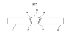
- FIG. 2 is a diagram schematically showing the vicinity of a welded portion of a welded joint joined by butt welding.
- Two steel plates 21 and 22 are joined at a welded portion 23 consisting of a weld bead formed by arc welding.
- FIG. 2 is a vertical sectional view, and the steel plates 21 and 22 and the welded portion 23 extend in the direction perpendicular to the plane of the paper.
- the weld portion 23 has a bead toe portion 24 that is a portion where the surface of the weld bead and the surface of the steel plate intersect.
- a heat affected zone 25 is formed around the welded portion 23 .
- C 0.05-0.40%
- C (carbon) is an element that ensures the strength of steel.
- the C content is set to 0.05 MPa in consideration of the balance with weldability and to prevent the C concentration in the surface layer of the steel sheet from becoming too high. ⁇ 0.40%. If the C content is too large, the C concentration in the surface layer of the steel sheet will not be reduced even by high dew point annealing, which will be described later.
- the content limit of C may be 0.07% or more, 0.10% or more, or 0.12% or more.
- the content of C may be 0.35% or less, 0.30% or less, or 0.25% or less.
- Si Si: 0.7-3.0%, sol.Al: 0.2-2.0%, Si+sol.Al ⁇ 1.0%)
- Si silicon
- Al aluminum
- the total content of Al is 1.0% or more.
- sol. Al refers to acid-soluble Al that is not converted into oxides such as Al 2 O 3 and is soluble in acids, and was measured by subtracting the insoluble residue on the filter paper that is generated during the Al analysis process. Required as Al.
- the content of Si may be 0.8% or more, 0.9% or more, or 1.0% or more.
- the content of Si may be 2.8% or less, 2.5% or less, or 2.0% or less.
- the Al content may be 0.3% or more, 0.4% or more, or 0.5% or more. sol.
- the Al content may be 1.8% or less, 1.6% or less, or 1.5% or less.
- the total content of Al may be 1.2% or more, 1.4% or more, 1.6% or more, or 1.8% or more.
- Mn manganese
- Mn manganese
- Mn content is set to 0.1 to 5.0%.
- the Mn content may be 0.5% or more, 1.0% or more, or 1.5% or more.
- the Mn content may be 4.5% or less, 4.0% or less, or 3.5% or less.
- P 0.0300% or less
- P phosphorus
- the content of P may be 0.0200% or less, 0.0100% or less, or 0.0050% or less. It is preferable that P is not contained, and the lower limit of the P content is 0%. From the viewpoint of dephosphorization cost, the P content may be more than 0%, 0.0001% or more, or 0.0005% or more.
- S sulfur
- S is an impurity generally contained in steel. If the S content exceeds 0.0300%, weldability will decrease, and furthermore, the amount of MnS precipitated may increase, leading to a possibility that workability such as bendability will decrease. Therefore, the S content is set to 0.0300% or less.
- the S content may be 0.0100% or less, 0.0050% or less, 0.0030% or less, 0.0020% or less, or 0.0010% or less. It is preferable that S is not contained, and the lower limit of the S content is 0%. From the viewpoint of desulfurization cost, the S content may be more than 0%, 0.0001% or more, or 0.0005% or more.
- N nitrogen
- nitrogen is an impurity generally contained in steel. If the N content exceeds 0.0100%, weldability may deteriorate. Therefore, the N content is set to 0.0100% or less.
- the content of N may be 0.0080% or less, 0.0050% or less, 0.0030% or less, 0.0020% or less, or 0.0010% or less. It is preferable that N is not contained, and the lower limit of the N content is 0%. From the viewpoint of manufacturing cost, the N content may be more than 0%, 0.0001% or more, 0.0002% or more, 0.0003% or more, or 0.0005% or more.
- B (boron) is an element that increases hardenability and contributes to improvement of strength, and also segregates at grain boundaries to strengthen grain boundaries and improve toughness, so it may be included as necessary. . Since B is not an essential element, the lower limit of the content of B is 0%. Although this effect can be obtained even when B is contained in a trace amount, it is preferable that the content of B is 0.0001% or more.
- the content of B may be 0.0002% or more, 0.0003% or more, 0.0005% or more, 0.0007% or more, or 0.0010% or more.
- the content of B is set to 0.010% or less.
- the content of B may be 0.0080% or less, 0.0060% or less, 0.0050% or less, 0.0040% or less, or 0.0030% or less.
- Ti titanium
- Ti titanium
- Ti titanium
- the lower limit of the content of Ti is 0%.
- the content of Ti is preferably 0.0001% or more.
- the content of Ti may be 0.0002% or more, 0.0003% or more, 0.0005% or more, 0.0007% or more, or 0.0010% or more.
- coarse TiN may be generated and toughness may be impaired, so the content of Ti is set to 0.150% or less.
- the Ti content is 0.1000% or less, 0.0500% or less, 0.0300% or less, 0.0200% or less, 0.0100% or less, 0.0050% or less, or 0.0030% or less. good.
- Nb 0-0.150% Since Nb (niobium) is an element that contributes to improving strength through improving hardenability, it may be included as necessary. Since Nb is not an essential element, the lower limit of the content of Nb is 0%. Although this effect can be obtained even with a trace amount of Nb, the content of Nb is preferably 0.001% or more. The Nb content may be 0.002% or more, 0.003% or more, 0.005% or more, or 0.008% or more. On the other hand, from the viewpoint of ensuring sufficient toughness, the Nb content is set to 0.150% or less. The Nb content may be 0.100% or less, 0.060% or less, 0.050% or less, 0.040% or less, or 0.030% or less.
- V vanadium
- V vanadium
- the lower limit of the content of V is 0%.
- the content of V is set to 0.150% or less.
- the V content may be 0.100% or less, 0.060% or less, 0.050% or less, 0.040% or less, 0.030% or less, or 0.020% or less.
- Cr 0-2.00% Cr (chromium) is effective in improving the hardenability of steel and increasing the strength of steel, and therefore may be contained as necessary. Since Cr is not an essential element, the lower limit of the content of Cr is 0%. Although this effect can be obtained even with a trace amount of Cr, the content of Cr is preferably 0.001% or more. The content of Cr may be 0.01% or more, 0.02% or more, 0.03% or more, 0.05% or more, or 0.08% or more. On the other hand, if it is contained excessively, a large amount of Cr carbide will be formed, and the hardenability may be adversely affected, so the content of Cr is set to 2.00% or less. The Cr content is 1.80% or less, 1.50% or less, 1.20% or less, 1.00% or less, 0.70% or less, 0.50% or less, or 0.30% or less. good.
- Ni nickel
- Ni nickel
- the lower limit of the Ni content is 0%.
- the Ni content may be 0.01% or more, or 0.02% or more.
- the Ni content is set to 2.00% or less.
- the Ni content is 1.80% or less, 1.50% or less, 1.20% or less, 1.00% or less, 0.80% or less, 0.50% or less, 0.30% or less, 0.20 % or less, 0.10% or less, or 0.05% or less.
- Cu (Cu: 0-2.00%) Cu (copper) is effective in improving the hardenability of steel and increasing the strength of steel, and therefore may be contained as necessary. Since Cu is not an essential element, the lower limit of the content of Cu is 0%. Although this effect can be obtained even with a trace amount of Cu, the content of Cu is preferably 0.0001% or more. The content of Cu may be 0.0002% or more, 0.0003% or more, or 0.0005% or more. On the other hand, from the viewpoint of suppressing a decrease in toughness and cracking of the slab after casting, the content of Cu is set to 2.00% or less.
- the Cu content is 1.8000% or less, 1.5000% or less, 1.2000% or less, 1.0000% or less, 0.5000% or less, 0.1000% or less, 0.0500% or less, 0.0100 % or less, 0.0050% or less, 0.0030% or less, or 0.0020% or less.
- Mo mobdenum
- Mo mobdenum
- the lower limit of the content of Mo is 0%.
- the content of Mo is preferably 0.001% or more.
- the Mo content may be 0.01% or more, 0.02% or more, 0.03% or more, 0.05% or more, or 0.08% or more.
- the Mo content is set to 1.00% or less.
- the Mo content may be 0.90% or less, 0.70% or less, 0.50% or less, or 0.30% or less.
- W 0-1.00% W (tungsten) is effective in increasing the hardenability of steel and increasing the strength of steel, and therefore may be included as necessary. Since W is not an essential element, the lower limit of the content of W is 0%. Although this effect can be obtained even when a small amount of W is included, it is preferable that the content of W is 0.001% or more. The content of W may be 0.002% or more, 0.005% or more, or 0.01% or more. On the other hand, from the viewpoint of suppressing a decrease in toughness, the content of W is set to 1.00% or less. The content of W is 0.90% or less, 0.70% or less, 0.50% or less, 0.30% or less, 0.10% or less, 0.05% or less, or 0.03% or less. good. .
- Ca (Ca: 0-0.100%)
- Ca (calcium) is an element that contributes to control of inclusions, particularly fine dispersion of inclusions, and has the effect of increasing toughness, and therefore may be contained as necessary. Since Ca is not an essential element, the lower limit of the content of Ca is 0%. Although this effect can be obtained even with a trace amount of Ca, the content of Ca is preferably 0.0001% or more. The content of Ca may be 0.0002% or more. On the other hand, since excessive Ca content may cause deterioration of surface properties, the Ca content is set to 0.100% or less.
- the content of Ca is 0.0800% or less, 0.0500% or less, 0.0100% or less, 0.0050% or less, 0.0030% or less, 0.0020% or less, 0.0010% or less, 0.0008 % or less, or 0.0005% or less.
- Mg manganesium
- Mg is an element that contributes to control of inclusions, particularly to fine dispersion of inclusions, and has the effect of increasing toughness, and therefore may be contained as necessary. Since Mg is not an essential element, the lower limit of the Mg content is 0%. Although this effect can be obtained even with a trace amount of Mg, it is preferable that the Mg content is 0.0001% or more.
- the content of Mg may be 0.0002% or more, 0.0003% or more, 0.0005% or more, or 0.0008% or more.
- the content of Mg is set to 0.100% or less.
- the Mg content may be 0.090% or less, 0.080% or less, 0.050% or less, 0.010% or less, 0.005% or less, or 0.003% or less.
- Zr zirconium
- Zr zirconium
- Zr zirconium
- Zr zirconium
- the content of Zr may be 0.002% or more, 0.003% or more, 0.005% or more, or 0.010% or more.
- the content of Zr is set to 0.100% or less.
- the content of Zr may be 0.080% or less, 0.050% or less, 0.040% or less, or 0.030% or less.
- Hf (hafnium) is an element that contributes to inclusion control, particularly fine dispersion of inclusions, and has the effect of increasing toughness, and therefore may be contained as necessary. Since it is not an essential element, the lower limit of the content of Hf is 0%. Although this effect can be obtained even with a trace amount of Hf, it is preferable that the Hf content is 0.0001% or more.
- the Hf content may be 0.0002% or more, 0.0003% or more, 0.0005% or more, or 0.0008% or more.
- the content of Hf is set to 0.100% or less.
- the Hf content may be 0.050% or less, 0.030% or less, 0.010% or less, 0.005% or less, or 0.003% or less.
- REM 0-0.100%
- REM rare earth element
- the lower limit of the content of REM is 0%.
- the content of REM is preferably 0.0001% or more.
- the content of REM may be 0.0003% or more, or 0.0005% or more.
- the content of REM is set to 0.100% or less.
- the content of REM may be 0.0500% or less, 0.0300% or less, 0.0100% or less, 0.0050% or less, 0.0030% or less, or 0.0020% or less.
- REM is an abbreviation for Rare Earth Metal, and refers to an element belonging to the lanthanide series. REM is usually added as a misch metal.
- the remainder other than the above chemical components consists of Fe and impurities.
- impurities are components that are mixed in due to various factors in the manufacturing process, including raw materials such as ore and scrap when manufacturing steel sheets industrially, and are components that are mixed in due to various factors in the manufacturing process, including raw materials such as ore and scrap. It means a substance that does not have an adverse effect on LME resistance.
- the chemical components of the steel plate may be analyzed using elemental analysis methods known to those skilled in the art, such as inductively coupled plasma mass spectrometry (ICP-MS).
- ICP-MS inductively coupled plasma mass spectrometry
- C and S may be measured using the combustion-infrared absorption method
- N may be measured using the inert gas melting-thermal conductivity method.
- the plated steel sheet constituting the welded joint of the present invention has a Zn-containing plating layer formed on a surface corresponding to at least a part of the non-heat-affected zone during welding among the surfaces of the base steel sheet and the base steel sheet. Be prepared.
- the plating layer is not particularly limited as long as it contains Zn. As an example, Zn-0.2%Al, Zn-0.5%Al, Zn-1.5%-Al-1.5%Mg, Zn-20%Al-7%Mg, Zn-30%Al- 10% Mg is mentioned.
- the plating layer may be formed on surfaces other than the surface corresponding to the non-heat affected zone.
- the chemical composition of the plating layer can be determined by dissolving the plating layer in an acid solution containing an inhibitor that suppresses corrosion of the steel sheet, and measuring the resulting solution by ICP (inductively coupled plasma) emission spectroscopy.
- the acid solution containing an inhibitor may be, for example, a 10% by mass hydrochloric acid solution containing 0.06% by mass of an inhibitor (manufactured by Asahi Chemical Co., Ltd., Ivit).
- the thickness of the plating layer may be, for example, 3 to 50 ⁇ m. Further, the amount of the plating layer deposited is not particularly limited, but may be, for example, 10 to 170 g/m 2 per side. In the present invention, the amount of the plating layer deposited is determined by dissolving the plating layer in an acid solution containing an inhibitor that suppresses corrosion of the base steel plate, and from the change in weight of the plating layer before and after pickling and peeling. The thickness of the plating layer may be 5 ⁇ m or more, 10 ⁇ m or more, 15 ⁇ m or more, or 20 ⁇ m or more. The thickness of the plating layer may be 40 ⁇ m or less, or 30 ⁇ m or less.
- the amount of the plating layer deposited on one side may be 20 g/m 2 or more, 30 g/m 2 or more, 40 g/m 2 or more, or 50 g/m 2 or more.
- the amount of the plating layer deposited per side may be 150 g/m 2 or less, 130 g/m 2 or less, 120 g/m 2 or less, or 100 g/m 2 or less.
- the thickness of the steel plate constituting the welded joint of the present invention is not particularly limited. For example, it can be 0.6 to 3.2 mm.
- the plate thickness may be 0.8 mm or more, or 1.0 mm or more.
- the plate thickness may be 3.0 mm or less, 2.6 mm or less, 2.4 mm or less, 2.2 mm or less, 2.0 mm or less, or 1.8 mm or less.
- the C concentration measured by GDS is at a depth of 0.05% or less in the depth direction of the base metal.
- the length is 5 ⁇ m or more.
- a heat-affected zone is a region where the material properties have changed due to heat during the arc welding process, and can be confirmed by SEM observation.
- the non-heat affected zone is a portion other than the heat affected zone.
- Such a structure can be obtained by changing the chemical composition of the steel plate to one containing a large amount of Si and Al as described above, subjecting it to heat treatment as described below, and performing arc welding.
- the depth at which the C concentration is 0.05% or less is 5 ⁇ m or more, the effect of improving LME resistance during manufacturing can be obtained, so the upper limit of the depth is not particularly limited, and the depth is, for example, It may be 50 ⁇ m or less, 40 ⁇ m or less, or 30 ⁇ m or less.
- the depth at which the C concentration is 0.05% or less may be 7 ⁇ m or more, 8 ⁇ m or more, 10 ⁇ m or more, or 12 ⁇ m or more, and preferably 15 ⁇ m or more.
- the GDS measurement is performed five times in the thickness direction, and the average value of these measurements is taken as the C concentration.
- the measurement conditions are as follows.
- the starting point of "depth” is the interface between the base steel plate and the plating layer.
- the interface between the base steel plate and the plating layer is located at a position where the Fe concentration measured by GDS measurement is 93% of the Fe concentration at a depth of 150 ⁇ m.
- the roughness of the interface between the plating layer and the base steel plate in the cross section of the steel plate in the non-heat affected zone is 3.0 ⁇ m or less in terms of arithmetic mean height Ra defined by JIS B0601:2013. . As the roughness increases, cracks are more likely to occur due to stress concentration.
- the roughness of the interface may be 2.5 ⁇ m or less, or 2.0 ⁇ m or less in Ra.
- the roughness of the interface may be the surface roughness of the steel plate measured after removing the plating. The plating is removed by dissolving the plating layer in an acid solution containing an inhibitor that inhibits corrosion of the steel plate.
- the plating layer of the steel plate is formed in a range of 0 to 100 ⁇ m from the bead toe of the weld in the direction opposite to the weld (in the direction perpendicular to the weld boundary and away from the weld).
- the C concentration at a depth of 5 ⁇ m in the base steel plate starting from the interface of the base steel plate is 0.05% or less.
- LME susceptibility decreases as the C concentration decreases, so by lowering the C concentration outside the bead toe of the weld, LME resistance during welded joint manufacturing can be improved.
- the C concentration at a depth of 5 ⁇ m in the base steel sheet starting from the interface between the plating layer of the steel sheet and the base steel sheet is 0.
- a content of .02% or less is preferable from the viewpoint of improving LME resistance.
- the C concentration at a depth of 5 ⁇ m in the base steel plate starting from the interface between the plating layer of the steel plate and the base steel plate in the range of 0 to 100 ⁇ m in the direction opposite to the weld is more preferably 0.01% or less. .
- C concentration is measured by SEM-EPMA.
- the measurement method is as follows. An observation sample is cut out from the welded joint so as to include the range of 0 to 100 ⁇ m outside the bead toe, and the cross section in the thickness direction of the steel plate is mirror polished. Subsequently, using EPMA, the polished observation sample is subjected to point analysis using a calibration curve method. Point analysis refers to quantitative analysis in which the measurement range is set to 0 ⁇ m in diameter.
- the EPMA device for example, JXA-8500 manufactured by JEOL Ltd. can be used.
- the EPMA analysis conditions are an accelerating voltage of 15 kV and an irradiation current of 5 ⁇ 10 ⁇ 7 A.
- the observation magnification is 5000x.
- the calibration curve is created by preparing Fe-0.01%C, Fe-0.05%C, and Fe-0.10%C alloys and measuring the average C concentration of the above alloys under the above conditions. .
- Measurement by point analysis is performed at a depth of 5 ⁇ m starting from the interface between the plating layer of the steel plate and the base steel sheet, and is performed in a range of 0 to 100 ⁇ m outside the bead toe in 5 ⁇ m increments, and the measured values at each position are calculated.
- the average value is taken as the C concentration at a depth of 5 ⁇ m in the range of 0 to 100 ⁇ m in the direction opposite to the weld.
- the steel plates forming the welded joint have high strength. Specifically, it has a tensile strength of 780 MPa or more.
- the upper limit of the tensile strength is not particularly limited, but from the viewpoint of ensuring toughness, it may be, for example, 2000 MPa or less.
- the tensile strength may be measured in accordance with JIS Z 2241:2011 by taking a JIS No. 5 tensile test piece whose longitudinal direction is perpendicular to the rolling direction.
- the tensile strength may be 880 MPa or more, 980 MPa or more, 1080 MPa or more, or 1180 MPa or more.
- the tensile strength may be 1900 MPa or less, or 1800 MPa or less.
- the hardness of the steel plate in the non-heat-affected zone located at a distance of 5 mm or more from the outer edge of the spot weld can be measured, and the tensile strength value can be estimated from the following correlation formula (Correlation between static strength parameters, Norihiko Hasegawa, Junichi Arai, Doshichi Tanaka, "Materials" Vol. 39, No. 442) , P859-863).
- Hv 0.301 ⁇ TS+5.701 (However, Hv is Vickers hardness and TS is tensile strength (unit: MPa))
- the tensile strength can be considered to be 780 MPa or more.
- the hardness of the steel plate is measured at a position that is the non-heat-affected zone of the steel plate that constitutes the welded joint, at a position 1/2 the depth. Hardness measurement is performed in accordance with JIS Z 2244:2009. The measurement load is 200 gf.
- the hardness of the steel plate in the non-heat affected zone located at a distance of 5 mm or more from the outer edge of the spot weld may be 245 Hv or more, 250 Hv or more, 260 Hv or more, 270 Hv or more, 300 Hv or more, or 340 Hv or more.
- the steel plate constituting the welded joint according to the present invention can be produced, for example, by a casting process in which molten steel with adjusted chemical composition is cast to form a steel billet, a hot rolling process in which a hot rolled steel plate is obtained by hot rolling a steel billet, or a hot rolling process in which a hot rolled steel plate is obtained by hot rolling a steel billet.
- the conditions of the casting process are not particularly limited. For example, following melting in a blast furnace, electric furnace, etc., various secondary smelting may be performed, and then casting may be performed by a method such as ordinary continuous casting or ingot casting.
- a hot rolled steel plate can be obtained by hot rolling a steel piece obtained by casting.
- the hot rolling process is performed by directly or once cooling the cast steel billet, then reheating and hot rolling.
- the heating temperature of the steel piece may be, for example, 1100 to 1250°C.
- rough rolling and finish rolling are usually performed.
- the temperature and reduction rate of each rolling may be changed as appropriate depending on the desired metal structure and plate thickness.
- the finishing temperature of finish rolling may be 900 to 1050°C, and the reduction ratio of finish rolling may be 10 to 50%.
- Hot-rolled steel sheets can be rolled up at a predetermined temperature.
- the winding temperature may be changed as appropriate depending on the desired metal structure, etc., and may be, for example, 500 to 800°C.
- the hot-rolled steel sheet may be subjected to a predetermined heat treatment by unwinding the hot-rolled steel sheet before or after winding.
- the hot-rolled steel sheet After pickling or the like is performed on the hot-rolled steel sheet, the hot-rolled steel sheet can be cold-rolled to obtain a cold-rolled steel sheet.
- the rolling reduction ratio of cold rolling may be changed as appropriate depending on the desired metallographic structure and plate thickness, and may be, for example, 20 to 80%.
- the material After the cold rolling process, the material may be cooled to room temperature by, for example, air cooling.
- the depth where the C concentration measured by GDS is 0.05% or less in the depth direction of the base metal is determined. 5 ⁇ m or more, from the bead toe of the weld in the range of 0 to 100 ⁇ m in the direction opposite to the weld, at a depth of 5 ⁇ m in the base steel plate starting from the interface between the plating layer of the steel plate and the base steel plate.
- the pretreatment includes grinding the surface of the cold rolled steel plate with a grinding brush (brush grinding process).
- a grinding brush that can be used is M-33 manufactured by Hotani Corporation. Thereby, strain can be introduced without increasing the surface roughness.
- the brush reduction amount is 0.5 to 10.0 mm and the rotation speed is 100 to 1000 rpm.
- the cold rolled steel sheet is annealed.
- Annealing is performed under a tension of 1 to 20 MPa. Applying tension during annealing makes it possible to more effectively introduce strain into the steel sheet, promoting decarburization of the surface layer.
- the holding temperature in the annealing step is 750 to 900°C.
- the holding temperature may be 770-870°C. By setting it within such a range, decarburization can be promoted, the C concentration in the surface layer can be reduced, and the ferrite phase can be stabilized.
- the heating rate up to the holding temperature is not particularly limited, but may be 1 to 10° C./sec.
- the holding time at the holding temperature in the annealing step is 20 to 300 seconds.
- the holding time may be between 30 and 250 seconds.
- the atmosphere in the annealing step has a dew point of -30 to 20°C.
- the dew point may be -10 to 5°C.
- the atmosphere may be, for example, N 2 -1 to 10 vol% H 2 or N 2 -2 to 4 vol% H 2 . If the dew point is too high or too low, a phase containing oxides such as Si, Mn, and Al is formed outside the steel sheet, which inhibits the mutual diffusion of the plating components and steel components, resulting in insufficient plating properties. There is.
- the plated steel plate constituting the welded joint according to the present invention can be obtained by performing a plating process to form a plating layer containing Zn on the steel plate manufactured as described above.
- the plating treatment may be performed according to methods known to those skilled in the art.
- the plating treatment may be performed, for example, by hot-dip plating or electroplating.
- the plating process is performed by hot-dip plating.
- the conditions for the plating treatment may be appropriately set in consideration of the chemical composition, thickness, amount of adhesion, etc. of the desired plating layer. For example, plating that may be immersed in a hot-dip galvanizing bath at 420 to 480°C with adjusted chemical components for 1 to 10 seconds, pulled out at 20 to 200 mm/sec after immersion, and controlling the amount of plating deposited with N 2 wiping gas.
- an alloying treatment may be performed.
- the alloying treatment may be performed, for example, at 500 to 550° C. for 10 to 60 seconds.
- ⁇ Arc welding process> A welded joint is obtained by overlapping or butting two of the above-mentioned steel plates and arc welding them.
- the welding conditions of arc welding and the wire used are not particularly limited. For example, welding current: 80 to 300 A, welding voltage: 15 to 35 V, welding speed: 50 to 200 cm/min, welding gas: 10 to 30% CO 2 Arc welding can be performed with +Ar and flow rate: 10 to 30 L/min.
- the welded joint according to the present invention suppresses LME cracking during manufacturing, it can be suitably used in a wide range of fields such as automobiles, home appliances, and building materials. It is particularly preferred to be used in the automotive field.
- Table 1 No. Molten steel adjusted to have the chemical composition described in 1 was melted in a blast furnace and cast by continuous casting to obtain a steel billet.
- the obtained steel piece was heated to 1200°C and hot rolled at a finish rolling end temperature of 950°C and a finish rolling reduction of 30% to obtain a hot rolled steel plate.
- the obtained hot-rolled steel sheet was wound up at a winding temperature of 650° C., pickled, and then cold-rolled at a rolling reduction of 50% to obtain a cold-rolled steel sheet.
- the thickness of the cold-rolled steel plate was 1.6 mm.
- the surface roughness of the steel plate was measured in accordance with JIS B 0601:2013. That is, 10 locations are randomly selected on the surface of the surface layer side, the surface profile at each location is measured using a contact type surface roughness meter, and the arithmetic mean roughness Ra is obtained by arithmetic averaging of the surface roughness at those locations. , was evaluated as follows.
- Evaluation AA 2.0 ⁇ m or less Evaluation A: More than 2.0 ⁇ m, 3.0 ⁇ m or less Evaluation B: More than 3.0 ⁇ m
- annealing was performed in a N 2 -4% H 2 gas atmosphere in a furnace with an oxygen concentration of 20 ppm or less at a dew point of 0° C., a holding temperature of 800° C., and a holding time of 20 seconds to prepare a steel plate sample.
- the temperature increase rate during annealing was 6.0°C/sec up to 500°C, and 2.0°C/sec from 500°C to the holding temperature.
- the annealing treatment was performed under a tension of 15 MPa.
- the steel plate was subjected to a plating treatment to obtain a hot-dip galvanized steel plate.
- the plating treatment was performed by immersing the sample in a hot-dip galvanizing bath (Zn-0.2% Al) at 460° C. for 3 seconds. After dipping, it was pulled out at 100 mm/sec, and the amount of plating deposited was controlled to 50 g/m 2 using N 2 wiping gas.
- Examples 2 to 28, Comparative Examples 29 to 41 A steel plate was prepared in the same manner as in Example 1, except that the chemical components were as shown in Table 1, the conditions for the pretreatment process and annealing process were as shown in Table 2, and the plating type was as shown in Table 3. Manufactured. In addition, No. In No. 40, the pretreatment of brush grinding was omitted. Also, No. In No. 41, a grinding brush D-100 manufactured by Hotani Co., Ltd. was used (condition B in Table 2). D-100 is a brush with approximately twice the amount of grinding as M-33.
- composition and bath temperature of the plating species shown in Table 3 are as follows. After the plating treatment, F was subjected to alloying treatment at 530° C. for 20 seconds to obtain alloyed hot-dip galvanizing.
- Evaluation AAA 1180MPa or more Evaluation AA: 980MPa or more, less than 1180MPa Evaluation A: 780MPa or more, less than 980MPa
- LME resistance evaluation For each steel plate, two identical steel plates were gas-shielded arc welded to form a weld bead to produce a lap fillet welded joint, and the LME suppression effect (LME resistance) during manufacturing was evaluated.
- the welding conditions were as follows.
- Welding current 250A Welding voltage: 26.2V Welding speed: 80cm/min Welding gas: 20% CO 2 +Ar, flow rate: 20L/min Welding wire: YM-24T ( ⁇ 1.2mm)) Made by Nippon Steel Welding Industry Welding torch angle of inclination: 60° Overlapping allowance: 10mm Steel plate size: Upper plate side 150 x 50mm, lower plate side 150 x 30mm Gap: 0mm Wire protrusion length: 15mm
- LME resistance was evaluated as follows based on the length of LME cracks that occurred. If the evaluation was "A" or higher, it was determined that the LME resistance was excellent and the problem to be solved by the present invention was solved.
- Evaluation AAA 0 ⁇ m Evaluation AA: More than 0 ⁇ m and less than 60 ⁇ m Evaluation A: More than 60 ⁇ m and less than 120 ⁇ m Evaluation B: More than 120 ⁇ m
- the plating was removed using a 10 mass% hydrochloric acid solution containing 0.06 mass% inhibitor (manufactured by Asahi Chemical Co., Ltd., Ivit) at the position that would become the non-heat affected zone, and the surface roughness of the exposed steel plate was was measured in the same manner as before annealing, and is shown in "Base material steel plate/plating interface roughness" in Table 3.
- An observation sample was cut out from the welded joint so as to cover a range of 0 to 100 ⁇ m from the bead toe in the direction opposite to the weld, and the cross section in the thickness direction of the steel plate was mirror-polished. Subsequently, using EPMA, the polished observation sample was subjected to point analysis using a calibration curve method.
- the EPMA device JXA-8500 manufactured by JEOL Ltd. was used.
- the EPMA analysis conditions were an accelerating voltage of 15 kV, an irradiation current of 5 ⁇ 10 ⁇ 7 A, and an observation magnification of 5000 times.
- the calibration curve was created by measuring the average C concentration of Fe-0.01%C, Fe-0.05%C, and Fe-0.10%C alloys under different conditions.
- Measurement by point analysis is performed at a depth of 5 ⁇ m starting from the interface between the plating layer of the steel plate and the base steel sheet, and is carried out in 5 ⁇ m increments in the range of 0 to 100 ⁇ m from the bead toe in the direction opposite to the weld.
- the average value of the measured values at the positions was taken as the C concentration at a depth of 5 ⁇ m in the range of 0 to 100 ⁇ m.
- No. No. 29 is a comparative example in which the steel plate has a high C content. It is thought that because the steel sheet has a high C content, decarburization in the surface layer did not proceed even with high dew point annealing. Therefore, the depth at which the C concentration measured by GDS in the non-heat-affected zone is 0.05% or less becomes smaller, and the C concentration at a position 0 to 100 ⁇ m from the bead toe in the direction opposite to the weld zone decreases. It got expensive. As a result, the LME resistance during manufacture of welded joints was inferior.
- No. No. 30 has a low Si content in the steel plate, and Si and sol.
- the Si content of the steel plate is low, and Si and sol. It is considered that because the sum of the Al contents was small, decarburization did not progress in the surface layer even if high dew point annealing was performed, and the ferrite was not stabilized. Therefore, the depth at which the C concentration measured by GDS in the non-heat-affected zone is 0.05% or less becomes smaller, and the C concentration at a position 0 to 100 ⁇ m from the bead toe in the direction opposite to the weld zone decreases. It got expensive. As a result, the LME resistance during manufacture of welded joints was inferior.
- No. No. 31 is a comparative example in which the steel plate has a low Si content. It is thought that because the Si content of the steel sheet was low, decarburization did not proceed in the surface layer even though high dew point annealing was performed, and ferrite was not stabilized. Therefore, the depth at which the C concentration measured by GDS in the non-heat-affected zone is 0.05% or less becomes smaller, and the C concentration at a position 0 to 100 ⁇ m from the bead toe in the opposite direction to the weld zone becomes smaller. It got expensive. As a result, the LME resistance during manufacture of welded joints was inferior.
- No. No. 32 is a comparative example in which the steel plate has a high Si content. It is thought that because the Si content of the steel sheet was high, even if high dew point annealing was performed, external oxidation progressed and oxides (scale) were formed on the surface layer of the steel sheet, suppressing decarburization at the outermost surface. Therefore, the depth at which the C concentration measured by GDS in the non-heat-affected zone is 0.05% or less becomes smaller, and the C concentration at a position 0 to 100 ⁇ m from the bead toe in the direction opposite to the weld zone decreases. It got expensive. As a result, the LME resistance during manufacture of welded joints was inferior.
- No. 33 is the steel plate sol. This is a comparative example with a low Al content. Steel plate sol. It is thought that because the Al content was low, decarburization did not proceed in the surface layer even though high dew point annealing was performed, and the ferrite was not stabilized. Therefore, the depth at which the C concentration measured by GDS in the non-heat-affected zone is 0.05% or less becomes smaller, and the C concentration at a position 0 to 100 ⁇ m from the bead toe in the direction opposite to the weld zone decreases. It got expensive. As a result, the LME resistance during manufacture of welded joints was inferior.
- No. 34 is the steel plate sol. This is a comparative example with a high content of Al. Steel plate sol. It is thought that because the Al content was high, even if high dew point annealing was performed, external oxidation progressed and oxides (scale) were formed on the surface layer of the steel sheet, suppressing decarburization at the outermost surface. Therefore, the C concentration at a position 0 to 100 ⁇ m from the bead toe in the direction opposite to the welded portion became high. As a result, the LME resistance during manufacture of welded joints was inferior.
- No. 35 is Si and sol. This is a comparative example in which the sum of the Al contents is small. Si and sol. of steel plate. It is considered that because the sum of the Al contents was small, decarburization did not progress in the surface layer even if high dew point annealing was performed, and the ferrite was not stabilized. Therefore, the depth at which the C concentration measured by GDS in the non-heat-affected zone is 0.05% or less becomes smaller, and the C concentration at a position 0 to 100 ⁇ m from the bead toe in the direction opposite to the weld zone decreases. It got expensive. As a result, the LME resistance during manufacture of welded joints was inferior.
- No. No. 42 is considered to be because a brush with a large amount of grinding was used in the pretreatment process, which resulted in increased roughness of the steel plate surface and unstable ferrite phase. Therefore, the C concentration at a position 0 to 100 ⁇ m from the bead toe in the direction opposite to the welded portion became high. As a result, the LME resistance during manufacture of welded joints was inferior.
- Examples 1 to 28 are examples of the present invention, in which LME was suppressed during the production of welded joints.
- the C concentration in the non-heat-affected zone is deep at a depth of 0.05% or less and the C concentration at a position 0 to 100 ⁇ m from the bead toe in the opposite direction to the weld is small, particularly excellent durability is achieved. It was confirmed that it had LME properties.
- the present invention it is possible to provide a welded joint in which LME cracking during manufacturing is suppressed, and the welded joint can be suitably used for applications such as automobiles, home appliances, and building materials, particularly for automobiles. Therefore, the present invention has extremely high industrial applicability.
Landscapes
- Chemical & Material Sciences (AREA)
- Engineering & Computer Science (AREA)
- Materials Engineering (AREA)
- Mechanical Engineering (AREA)
- Metallurgy (AREA)
- Organic Chemistry (AREA)
- Physics & Mathematics (AREA)
- Thermal Sciences (AREA)
- Crystallography & Structural Chemistry (AREA)
- Plasma & Fusion (AREA)
- Chemical Kinetics & Catalysis (AREA)
- Heat Treatment Of Sheet Steel (AREA)
Abstract
La présente invention aborde le problème de la fourniture d'un joint soudé qui n'a pas subi de fissuration de LME pendant la production. Ce joint soudé est caractérisé en ce que : le joint soudé est constitué de plaques d'acier plaquées ayant des composants chimiques donnés ; dans la partie non affectée par la chaleur de chaque plaque d'acier plaquée, les profondeurs auxquelles la concentration de C telle que déterminée par GDS est de 0,05 % ou moins sont de 5 µm ou plus à partir de l'interface en tant que point de départ entre la couche de placage et la plaque d'acier de base le long de la direction de profondeur de base ; dans une section transversale de la partie non affectée par la chaleur de la plaque d'acier, l'interface entre la couche de placage et la plaque d'acier de base a une rugosité de 3,0 µm ou moins en termes de Ra ; et dans la plage de 0 à 100 µm à partir de chaque bord du cordon de la soudure dans la direction opposée à la soudure, la concentration de C dans la plaque d'acier de base à une profondeur de 5 µm à partir de l'interface en tant que point de départ entre la couche de placage et la plaque d'acier de base est de 0,05 % ou moins.
Applications Claiming Priority (2)
| Application Number | Priority Date | Filing Date | Title |
|---|---|---|---|
| JP2022-141560 | 2022-09-06 | ||
| JP2022141560 | 2022-09-06 |
Publications (1)
| Publication Number | Publication Date |
|---|---|
| WO2024053665A1 true WO2024053665A1 (fr) | 2024-03-14 |
Family
ID=90191249
Family Applications (1)
| Application Number | Title | Priority Date | Filing Date |
|---|---|---|---|
| PCT/JP2023/032486 WO2024053665A1 (fr) | 2022-09-06 | 2023-09-06 | Joint soudé |
Country Status (1)
| Country | Link |
|---|---|
| WO (1) | WO2024053665A1 (fr) |
Citations (6)
| Publication number | Priority date | Publication date | Assignee | Title |
|---|---|---|---|---|
| WO2020130631A1 (fr) * | 2018-12-19 | 2020-06-25 | 주식회사 포스코 | Tôle d'acier galvanisée à haute résistance ayant une excellente soudabilité par point de résistance électrique et son procédé de fabrication |
| KR20220019867A (ko) * | 2020-08-10 | 2022-02-18 | 주식회사 포스코 | 우수한 점용접성, 강도 및 성형성을 갖는 냉연강판 및 그 제조방법 |
| WO2022097738A1 (fr) * | 2020-11-06 | 2022-05-12 | Jfeスチール株式会社 | FEUILLE D'ACIER ÉLECTROPLAQUÉE À BASE DE Fe, FEUILLE D'ACIER GALVANISÉE PAR IMMERSION À CHAUD ALLIÉE ET LEURS PROCÉDÉS DE FABRICATION |
| WO2022149507A1 (fr) * | 2021-01-08 | 2022-07-14 | 日本製鉄株式会社 | Joint de soudure et composant d'automobile |
| WO2022149505A1 (fr) * | 2021-01-08 | 2022-07-14 | 日本製鉄株式会社 | Joint soudé et pièce de véhicule |
| WO2022149511A1 (fr) * | 2021-01-08 | 2022-07-14 | 日本製鉄株式会社 | Joint soudé et composant d'automobile |
-
2023
- 2023-09-06 WO PCT/JP2023/032486 patent/WO2024053665A1/fr unknown
Patent Citations (6)
| Publication number | Priority date | Publication date | Assignee | Title |
|---|---|---|---|---|
| WO2020130631A1 (fr) * | 2018-12-19 | 2020-06-25 | 주식회사 포스코 | Tôle d'acier galvanisée à haute résistance ayant une excellente soudabilité par point de résistance électrique et son procédé de fabrication |
| KR20220019867A (ko) * | 2020-08-10 | 2022-02-18 | 주식회사 포스코 | 우수한 점용접성, 강도 및 성형성을 갖는 냉연강판 및 그 제조방법 |
| WO2022097738A1 (fr) * | 2020-11-06 | 2022-05-12 | Jfeスチール株式会社 | FEUILLE D'ACIER ÉLECTROPLAQUÉE À BASE DE Fe, FEUILLE D'ACIER GALVANISÉE PAR IMMERSION À CHAUD ALLIÉE ET LEURS PROCÉDÉS DE FABRICATION |
| WO2022149507A1 (fr) * | 2021-01-08 | 2022-07-14 | 日本製鉄株式会社 | Joint de soudure et composant d'automobile |
| WO2022149505A1 (fr) * | 2021-01-08 | 2022-07-14 | 日本製鉄株式会社 | Joint soudé et pièce de véhicule |
| WO2022149511A1 (fr) * | 2021-01-08 | 2022-07-14 | 日本製鉄株式会社 | Joint soudé et composant d'automobile |
Similar Documents
| Publication | Publication Date | Title |
|---|---|---|
| CN111492075B (zh) | 钢板、热浸镀锌钢板和合金化热浸镀锌钢板 | |
| JP6777173B2 (ja) | スポット溶接用高強度亜鉛めっき鋼板 | |
| TWI500780B (zh) | 熔融鍍鋅鋼板及其製造方法 | |
| WO2019189842A1 (fr) | Tôle d'acier galvanisée à résistance élevée, élément à résistance élevée et leurs procédés de fabrication | |
| CN108291283B (zh) | 高强度热浸镀锌钢板及用于其的热轧钢板和冷轧钢板的制造方法、高强度热浸镀锌钢板 | |
| WO2008084838A1 (fr) | Tôle d'acier inoxydable ferritique pour chauffe-eau, présentant une excellente résistance à la corrosion au niveau d'une partie soudée et une excellente ténacité de tôle | |
| KR20180133508A (ko) | 도금 강판 및 그의 제조 방법 | |
| JP7311040B2 (ja) | Fe系電気めっき鋼板の製造方法及び合金化溶融亜鉛めっき鋼板の製造方法 | |
| JP6102902B2 (ja) | 冷延鋼板、その製造方法、高強度溶融亜鉛めっき鋼板及び高強度合金化溶融亜鉛めっき鋼板 | |
| JP7311041B2 (ja) | Fe系電気めっき鋼板,電着塗装鋼板,自動車部品,電着塗装鋼板の製造方法,及びFe系電気めっき鋼板の製造方法 | |
| WO2022215389A1 (fr) | Tôle d'acier laminée à froid à haute résistance et son procédé de fabrication | |
| CN113272465B (zh) | 高强度冷轧钢板及其制造方法 | |
| JP7311042B2 (ja) | 亜鉛めっき鋼板,電着塗装鋼板,自動車部品,電着塗装鋼板の製造方法,及び亜鉛めっき鋼板の製造方法 | |
| JP7311043B2 (ja) | 合金化亜鉛めっき鋼板,電着塗装鋼板,自動車部品,電着塗装鋼板の製造方法,及び合金化亜鉛めっき鋼板の製造方法 | |
| JP2007015000A (ja) | 高強度電縫鋼管の製造方法 | |
| JP5978826B2 (ja) | 表面安定性に優れた高強度溶融亜鉛めっき鋼板の製造方法 | |
| WO2023054717A1 (fr) | Élément soudé en acier | |
| KR101999032B1 (ko) | 점용접성이 우수한 고강도 고망간 도금강판 용접 구조물 및 그의 제조방법 | |
| CN110402297B (zh) | 高强度热轧镀敷钢板 | |
| WO2024053665A1 (fr) | Joint soudé | |
| CN115362275B (zh) | 钢板、部件及其制造方法 | |
| EP4332251A1 (fr) | Élément soudé en acier | |
| WO2024053669A1 (fr) | Joint soudé | |
| WO2024053667A1 (fr) | Tôle d'acier et tôle d'acier plaquée | |
| WO2024053663A1 (fr) | Tôle d'acier plaquée |
Legal Events
| Date | Code | Title | Description |
|---|---|---|---|
| 121 | Ep: the epo has been informed by wipo that ep was designated in this application |
Ref document number: 23863203 Country of ref document: EP Kind code of ref document: A1 |