WO2024053028A1 - 光接続部品および光接続方法 - Google Patents
光接続部品および光接続方法 Download PDFInfo
- Publication number
- WO2024053028A1 WO2024053028A1 PCT/JP2022/033616 JP2022033616W WO2024053028A1 WO 2024053028 A1 WO2024053028 A1 WO 2024053028A1 JP 2022033616 W JP2022033616 W JP 2022033616W WO 2024053028 A1 WO2024053028 A1 WO 2024053028A1
- Authority
- WO
- WIPO (PCT)
- Prior art keywords
- optical
- adapter
- rotating member
- optical connector
- connection component
- Prior art date
- Legal status (The legal status is an assumption and is not a legal conclusion. Google has not performed a legal analysis and makes no representation as to the accuracy of the status listed.)
- Ceased
Links
Images





Classifications
-
- G—PHYSICS
- G02—OPTICS
- G02B—OPTICAL ELEMENTS, SYSTEMS OR APPARATUS
- G02B6/00—Light guides; Structural details of arrangements comprising light guides and other optical elements, e.g. couplings
- G02B6/24—Coupling light guides
- G02B6/36—Mechanical coupling means
-
- G—PHYSICS
- G02—OPTICS
- G02B—OPTICAL ELEMENTS, SYSTEMS OR APPARATUS
- G02B6/00—Light guides; Structural details of arrangements comprising light guides and other optical elements, e.g. couplings
- G02B6/24—Coupling light guides
- G02B6/36—Mechanical coupling means
- G02B6/38—Mechanical coupling means having fibre to fibre mating means
-
- G—PHYSICS
- G02—OPTICS
- G02B—OPTICAL ELEMENTS, SYSTEMS OR APPARATUS
- G02B6/00—Light guides; Structural details of arrangements comprising light guides and other optical elements, e.g. couplings
- G02B6/24—Coupling light guides
- G02B6/36—Mechanical coupling means
- G02B6/38—Mechanical coupling means having fibre to fibre mating means
- G02B6/3807—Dismountable connectors, i.e. comprising plugs
- G02B6/381—Dismountable connectors, i.e. comprising plugs of the ferrule type, e.g. fibre ends embedded in ferrules, connecting a pair of fibres
- G02B6/3825—Dismountable connectors, i.e. comprising plugs of the ferrule type, e.g. fibre ends embedded in ferrules, connecting a pair of fibres with an intermediate part, e.g. adapter, receptacle, linking two plugs
-
- G—PHYSICS
- G02—OPTICS
- G02B—OPTICAL ELEMENTS, SYSTEMS OR APPARATUS
- G02B6/00—Light guides; Structural details of arrangements comprising light guides and other optical elements, e.g. couplings
- G02B6/24—Coupling light guides
- G02B6/36—Mechanical coupling means
- G02B6/38—Mechanical coupling means having fibre to fibre mating means
- G02B6/3807—Dismountable connectors, i.e. comprising plugs
- G02B6/381—Dismountable connectors, i.e. comprising plugs of the ferrule type, e.g. fibre ends embedded in ferrules, connecting a pair of fibres
- G02B6/3826—Dismountable connectors, i.e. comprising plugs of the ferrule type, e.g. fibre ends embedded in ferrules, connecting a pair of fibres characterised by form or shape
- G02B6/3831—Dismountable connectors, i.e. comprising plugs of the ferrule type, e.g. fibre ends embedded in ferrules, connecting a pair of fibres characterised by form or shape comprising a keying element on the plug or adapter, e.g. to forbid wrong connection
-
- G—PHYSICS
- G02—OPTICS
- G02B—OPTICAL ELEMENTS, SYSTEMS OR APPARATUS
- G02B6/00—Light guides; Structural details of arrangements comprising light guides and other optical elements, e.g. couplings
- G02B6/24—Coupling light guides
- G02B6/36—Mechanical coupling means
- G02B6/38—Mechanical coupling means having fibre to fibre mating means
- G02B6/3807—Dismountable connectors, i.e. comprising plugs
- G02B6/3869—Mounting ferrules to connector body, i.e. plugs
- G02B6/3871—Ferrule rotatable with respect to plug body, e.g. for setting rotational position ; Fixation of ferrules after rotation
-
- G—PHYSICS
- G02—OPTICS
- G02B—OPTICAL ELEMENTS, SYSTEMS OR APPARATUS
- G02B6/00—Light guides; Structural details of arrangements comprising light guides and other optical elements, e.g. couplings
- G02B6/24—Coupling light guides
- G02B6/36—Mechanical coupling means
- G02B6/38—Mechanical coupling means having fibre to fibre mating means
- G02B6/3807—Dismountable connectors, i.e. comprising plugs
- G02B6/3873—Connectors using guide surfaces for aligning ferrule ends, e.g. tubes, sleeves, V-grooves, rods, pins, balls
- G02B6/3885—Multicore or multichannel optical connectors, i.e. one single ferrule containing more than one fibre, e.g. ribbon type
-
- G—PHYSICS
- G02—OPTICS
- G02B—OPTICAL ELEMENTS, SYSTEMS OR APPARATUS
- G02B6/00—Light guides; Structural details of arrangements comprising light guides and other optical elements, e.g. couplings
- G02B6/24—Coupling light guides
- G02B6/36—Mechanical coupling means
- G02B6/38—Mechanical coupling means having fibre to fibre mating means
- G02B6/3807—Dismountable connectors, i.e. comprising plugs
- G02B6/389—Dismountable connectors, i.e. comprising plugs characterised by the method of fastening connecting plugs and sockets, e.g. screw- or nut-lock, snap-in, bayonet type
- G02B6/3893—Push-pull type, e.g. snap-in, push-on
-
- G—PHYSICS
- G02—OPTICS
- G02B—OPTICAL ELEMENTS, SYSTEMS OR APPARATUS
- G02B6/00—Light guides; Structural details of arrangements comprising light guides and other optical elements, e.g. couplings
- G02B6/24—Coupling light guides
- G02B6/36—Mechanical coupling means
- G02B6/40—Mechanical coupling means having fibre bundle mating means
- G02B6/406—Mechanical coupling means having fibre bundle mating means of the ferrule type, connecting a plurality of pairs of ferrules
Definitions
- the present disclosure relates to optical connection components and optical connection methods.
- Patent Document 1 describes an optical connection component that optically connects a pair of optical connectors via an adapter.
- the optical connector includes an internal connector body that accommodates a first ferrule and a second ferrule, and a rear connector body that is connected to the internal connector body. Each of the first ferrule and the second ferrule holds an optical fiber.
- the rear connector body has a handle that extends in the opposite direction from the inner connector body.
- the internal connector body has a latch arm extending in the optical axis direction of the optical fiber.
- the adapter has a groove in which the latch arm engages.
- Patent Document 2 describes an optical connector.
- the optical connector includes an optical receptacle and an optical plug inserted into the optical receptacle.
- the optical plug has an engaging portion that engages with the optical receptacle.
- the engaging portion includes an engaging piece that is hooked on the optical receptacle, and a protrusion that fits into a hole formed in the optical receptacle.
- Patent Document 3 describes an adapter assembly.
- the adapter assembly includes an adapter, a plug inserted into the adapter, and a ferrule holder inserted into the plug and functioning as an optical connector.
- the ferrule holder accommodates a plurality of ferrules that hold optical fibers.
- the ferrule holder has a latch extending obliquely upward from the top surface. The ferrule holder is attached to the plug by the latch engaging the plug.
- Patent Document 4 describes an optical connector and a method for connecting the optical connector.
- the optical connector includes an optical receptacle and an optical plug coupled to the optical receptacle.
- the optical receptacle includes an outer housing, an inner housing, and a receptacle-side ferrule housed in the inner housing.
- the optical plug includes a plug-side housing and a plug-side ferrule housed in the plug-side housing.
- the inner housing has an engaging portion
- the plug-side housing has an engaged portion and an unlocking portion.
- Patent Document 5 describes a connection structure of an optical connector.
- This connection structure includes a plug receptacle having a port and a plug connector inserted into the port.
- the connection structure further includes a release member that allows removal of the plug connector from the port.
- An optical connection component includes: an optical connector having a ferrule that holds an optical fiber; a rotating member having an insertion hole into which the optical connector is inserted along the optical axis direction of the optical fiber; An adapter to which an optical connector is connected.
- the adapter has a latch that is engaged by an optical connector that moves along the optical axis direction.
- the rotating member has a moving mechanism that moves the optical connector along the optical axis direction by rotating relative to the adapter about a central axis extending along the optical axis direction.
- An optical connection method is an optical connection method in which an optical connector having an optical fiber is optically connected to a mating connector via an adapter, and the optical connector is inserted along the optical axis direction of the optical fiber.
- a rotary member having a hole is provided.
- the optical connection method includes a step of inserting an optical connector into an insertion hole.
- the optical connector is moved in the optical axis direction by rotating a rotating member relative to the adapter about a central axis extending along the optical axis direction, and the optical connector is engaged with a latch included in the adapter. Equipped with a process.
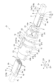
- FIG. 1 is a sectional view of an optical connection component according to an embodiment.
- FIG. 2 is a perspective view of the optical connection component of FIG. 1.
- 3 is an exploded perspective view of the optical connector of the optical connection component shown in FIG. 1.
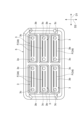
- FIG. 4 is a front view of the optical connector of FIG. 3.
- 5 is a perspective view showing the front housing of the optical connector shown in FIG. 4.
- FIG. 6 is a perspective view showing the middle housing of the optical connector shown in FIG. 4.
- FIG. 7 is a perspective view showing the rear housing of the optical connector shown in FIG. 4.
- FIG. 8 is a side view showing the adapter of the optical connection component in FIG. 1.
- FIG. 9 is a cross-sectional view of the adapter of FIG. 8.
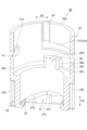
- FIG. 10 is a side view showing the rotating member of the optical connection component in FIG. 1.
- FIG. 11 is a perspective view showing the rotating member of FIG. 10.
- FIG. 12 is a cross-sectional perspective view of the rotating member of FIG. 10.
- FIG. 13 is a perspective view of the rear housing of FIG. 7.
- FIG. 14 is a diagram showing one step of the optical connection method according to the embodiment.
- FIG. 15 is a diagram showing one step of the optical connection method according to the embodiment.
- FIG. 16 is a diagram showing one step of the optical connection method according to the embodiment.
- FIG. 17 is a diagram showing one step of the optical connection method according to the embodiment.
- FIG. 18 is a diagram showing one step of the optical connection method according to the embodiment.
- FIG. 19 is a diagram showing one step of the optical connection method according to the embodiment.
- An object of the present disclosure is to provide an optical connection component and an optical connection method that can easily connect optical connectors.
- An optical connection component includes (1) an optical connector having a ferrule that holds an optical fiber, a rotating member having an insertion hole into which the optical connector is inserted along the optical axis direction of the optical fiber, and an insertion hole. an adapter to which an optical connector inserted into the adapter is connected.
- the adapter has a latch that is engaged by an optical connector that moves along the optical axis direction.
- the rotating member has a moving mechanism that moves the optical connector along the optical axis direction by rotating relative to the adapter about a central axis extending along the optical axis direction.
- the optical connector has a ferrule that holds an optical fiber, and the optical connector is connected to the adapter.
- the adapter has a movement mechanism that moves the optical connector along the optical axis direction. Since the adapter rather than the optical connector has a moving mechanism, the optical connector can be made smaller and the optical connector can be easily inserted into the adapter.
- the optical connection component includes a rotating member that rotates around a central axis extending along the optical axis direction, and the rotating member has an insertion hole into which the optical connector is inserted. The rotating member moves the optical connector in the optical axis direction by rotating. Therefore, the optical connector can be engaged with the latch by moving the optical connector in the optical axis direction by rotating the rotating member. Therefore, the optical connector can be easily connected.
- the rotating member may have a latch presser that presses the latch engaged with the optical connector.
- the latch presser can more reliably prevent the latch from opening. Therefore, the optical connector can be firmly engaged with the adapter.
- the moving mechanism may have an inclined surface that comes into contact with the optical connector inserted into the insertion hole.
- the rotating member may push out the optical connector in contact with the inclined surface toward the adapter by rotating.
- the configuration of the moving mechanism for moving the optical connector can be simplified. By rotating the rotating member while the optical connector is in contact with the inclined surface, the optical connector can be pushed out toward the adapter. Therefore, since the rotating member can be rotated to push out the optical connector toward the adapter, the optical connector can be easily connected to the adapter.
- the optical connector may include a plurality of ferrules and a housing unit that accommodates the plurality of ferrules. In this case, by accommodating the plurality of ferrules in the housing unit, the plurality of ferrules of the optical connector can be optically connected at once.
- the plurality of ferrules are lined up along the first direction intersecting the optical axis direction, and the second direction intersecting both the optical axis direction and the first direction. They may be lined up along the In this case, a plurality of ferrules arranged in the first direction and the second direction can be optically connected at once.
- the housing unit may include a front housing formed with a recessed portion that engages with the latch.
- the latch of the adapter can be engaged with the recess formed in the front housing of the optical connector.
- the front housing may have a rectangular parallelepiped shape.
- the front housing can be made into a simple shape, which contributes to further miniaturization of the optical connector.
- the ferrule may be housed in the front housing.
- the housing unit may include a middle housing including a space forming portion that forms a space through which the optical fiber held by the ferrule is passed.
- the optical fiber extending from the ferrule can be passed through the space of the middle housing.
- the optical connector may include a spring member interposed between the ferrule and the middle housing.
- the ferrule can be biased by the spring member.
- the housing unit may include a rear housing against which the moving mechanism comes into contact, and the middle housing may be accommodated in the rear housing.
- the moving mechanism can be brought into contact with the rear housing that accommodates the middle housing.
- the rear housing may have a cylindrical portion into which the optical fiber is inserted, and a protruding portion that protrudes from the cylindrical portion in a first direction intersecting the optical axis direction.
- the protrusion may fit into the insertion hole, and the moving mechanism may move the optical connector by abutting the protrusion that has entered the insertion hole. In this case, the moving mechanism can move the optical connector toward the adapter by coming into contact with the protruding part that protrudes from the cylindrical part in the first direction.
- the rear housing may have a non-circular shape in a cross section perpendicular to the optical axis direction. In this case, the rear housing can be inserted into the insertion hole even more easily.
- the rear housing and the insertion hole have a flat shape extending in the first direction intersecting the optical axis direction. It's okay. In this case, the rear housing can be inserted into the insertion hole even more easily.
- the rotating member may have a plurality of moving mechanisms arranged at positions sandwiching the insertion hole.
- the plurality of moving mechanisms move the optical connector, thereby making it easier to connect the optical connector to the adapter.
- the moving mechanism and the latch presser may be arranged side by side along the optical axis direction.
- the rotating member may have a plurality of latch holders arranged at positions sandwiching the insertion hole. In this case, since opening of the latch can be suppressed by the plurality of latch pressers, the optical connector can be more firmly engaged with the adapter.
- the rotating member may have a cylindrical adapter accommodating portion that accommodates the adapter. In this case, the rotating member can be rotated relative to the adapter while the adapter is accommodated.
- the adapter accommodating portion may have a slit extending along the rotation direction of the rotating member.
- the adapter may have a convex portion that is inserted into the slit. In this case, by rotating the rotating member relative to the adapter with the convex portion inserted into the slit, the rotating member can be smoothly rotated in the rotational direction.
- the slit may have an extending portion extending in the rotational direction and a depression recessed in the optical axis direction at the end of the extending portion in the rotational direction.
- the protrusion may fit into the recess when the optical connector engages the latch.
- the rotating member may move in the optical axis direction so that the moving mechanism separates from the optical connector when the convex portion enters the recess. In this case, when the optical connector engages with the latch, the rotating member moving mechanism can be moved away from the optical connector.
- the rotation angle of the rotating member with respect to the adapter may be 30° or more and 170° or less. In this case, a sufficient amount of movement of the optical connector that moves with the rotation of the rotating member can be ensured.
- the optical connection method according to the present disclosure is (22) an optical connection method in which an optical connector having an optical fiber is optically connected to a mating connector via an adapter, in which the optical connector is inserted along the optical axis direction of the optical fiber.
- the rotary member has an insertion hole.
- the optical connection method includes a step of inserting an optical connector into an insertion hole.
- the optical connector is moved in the optical axis direction by rotating a rotating member relative to the adapter about a central axis extending along the optical axis direction, and the optical connector is engaged with a latch included in the adapter. Equipped with a process.
- an optical connector is connected to an adapter, and the adapter has a movement mechanism that moves the optical connector along the optical axis direction. Since the adapter rather than the optical connector has a moving mechanism, the optical connector can be made smaller and the optical connector can be easily inserted into the adapter.
- the optical connection method uses a rotating member that has an insertion hole into which an optical connector is inserted and that rotates about a central axis that extends along the optical axis direction. The rotating member moves the optical connector in the optical axis direction by rotating. Therefore, the optical connector can be engaged with the latch by moving the optical connector in the optical axis direction by rotating the rotating member. Therefore, the optical connector can be easily connected.
- FIG. 1 is a cross-sectional view showing an example of an optical connection component 1.
- FIG. 2 is a perspective view showing the optical connection component 1.
- the optical connection component 1 includes an adapter 10 to which an optical connector 2 is connected, and a rotating member 20 rotatably attached to the adapter 10.
- the optical connector 2 and the mating connector 2A are connected to the adapter 10.
- the materials of the parts constituting each of the optical connection component 1 and the optical connector 2 include, for example, polycarbonate (PC), polyetherimide (PEI), polyamide (PA), polyacetal (POM), polyphenylene ether (PPE), and polybutylene.
- It may be a resin material such as terephthalate (PBT), polyphenylene sulfide (PPS), or polyethersulfone (PES), or a composite material in which the resin material is filled with glass fibers or glass spheres.
- PBT terephthalate
- PPS polyphenylene sulfide
- PES polyethersulfone
- the optical connector 2 is connected to the mating connector 2A by being connected to the adapter 10.
- the configuration of the mating connector 2A may be different from the configuration of the optical connector 2. However, below, an example will be described in which the configuration of the mating connector 2A is the same as the configuration of the optical connector 2, and the description of the configuration of the mating connector 2A will be omitted as appropriate.
- the optical connection component 1 includes, for example, one adapter 10 and two rotating members 20.
- the rotating member 20 is rotatably attached to the adapter 10 about a central axis L that extends along a direction D3 that intersects both the first direction D1 and the second direction D2, which are the width directions of the adapter 10.
- the adapter 10 has a latch 11 engaged by the optical connector 2 moving along the direction D3.
- the rotating member 20 connects the optical connector 2 to the adapter 10 by rotating about the central axis L.
- the second direction D2 is, for example, a direction orthogonal to the first direction D1.
- the direction D3 is, for example, a direction orthogonal to both the first direction D1 and the second direction D2.
- the optical connector 2 has, for example, a rectangular parallelepiped shape.
- the optical connectors 2 are connected to the adapter 10 so as to be lined up along the direction D3.
- Direction D3 corresponds to the direction in which the optical connector 2 is connected to the adapter 10.
- the rotating member 20 is provided inside to abut the optical connector 2 and push the optical connector 2 toward the center of the adapter 10 in the direction D3.
- the direction in which the optical connector 2 is pushed in may be referred to as the front, the front side, or the front, and the direction opposite to the direction in which the optical connector 2 is pushed in may be referred to as the rear, rear side, or back.
- FIG. 3 is an exploded perspective view of the optical connector 2.
- the optical connector 2 includes, for example, a ferrule 3 and a housing unit 4 that accommodates the ferrule 3.
- the housing unit 4 includes, for example, a front housing 5, a middle housing 6, and a rear housing 7.
- the optical connector 2 includes a spring member 8 that biases the ferrule 3 and a pin keeper 9 that holds a guide pin inserted into the ferrule 3.
- the optical connector 2 has, for example, a plurality of ferrules 3 housed in a housing unit 4.
- the plurality of ferrules 3 are lined up along the first direction D1 and lined up along the second direction D2.
- two ferrules 3 are lined up along the first direction D1, and three ferrules 3 are lined up along the second direction D2.
- FIG. 4 is a front view of the optical connector 2 when viewed from the direction D3.
- each ferrule 3 has an end surface 3b facing the mating connector 2A, and a guide hole 3c into which the aforementioned guide pin is inserted.
- the guide hole 3c penetrates the ferrule 3 in the direction D3.
- Two guide holes 3c are lined up along the first direction D1.
- the optical connector 2 has an optical fiber F held by a ferrule 3.
- the optical fiber F extends from the end surface 3b of the ferrule 3 in the direction D3.
- Direction D3 is the optical axis direction of optical fiber F.
- illustration of the optical fiber F is omitted except in FIG. 4.
- the ferrule 3 has a plurality of optical fiber holding holes 3d that hold the optical fibers F, and each optical fiber holding hole 3d passes through the ferrule 3 in the direction D3.
- a plurality of optical fiber holding holes 3d are formed between a pair of guide holes 3c on the end surface 3b.
- the plurality of optical fiber holding holes 3d are lined up along the first direction D1 and lined up along the second direction D2.
- the ferrule 3 has 32 optical fiber holding holes 3d.
- the number of fibers of the optical connector 2 (the number of optical fibers F) is 192 fibers.
- two optical fiber holding holes 3d are lined up along the second direction D2, and sixteen optical fiber holding holes 3d are lined up along the first direction D1.
- FIG. 5 is a perspective view showing the front housing 5.
- the front housing 5 has a rectangular parallelepiped shape.
- the length of the front housing 5 in the direction D3 is longer than the length of the front housing 5 in the first direction D1
- the length of the front housing 5 in the first direction D1 is longer than the length of the front housing 5 in the second direction D2.
- the front housing 5 includes, for example, a top surface portion 5b, a bottom surface portion 5c, and a pair of side surface portions 5d.
- the top surface portion 5b extends in both the first direction D1 and the direction D3, and the bottom surface portion 5c faces the opposite side from the top surface portion 5b.
- the pair of side surfaces 5d face the first direction D1 and are lined up along the first direction D1.
- a ferrule 3 is housed in the front housing 5.
- the front housing 5 has a first opening 5f through which the ferrule 3 is exposed, and a second opening 5g into which the middle housing 6 and rear housing 7 are inserted.
- the first opening 5f faces forward, and the second opening 5g faces rearward.
- the ferrule 3 protrudes from the first opening 5f.
- the front housing 5 has the same number of first openings 5f as the ferrules 3, and each ferrule 3 protrudes from each first opening 5f.
- the front housing 5 has a recess 5k that engages with a latch 11 of an adapter 10, which will be described later.
- the recessed portion 5k is formed in each of the pair of side portions 5d aligned along the first direction D1.
- the recess 5k when viewed from the first direction D1, has a rectangular shape.
- the recess 5k has a trapezoidal cross-sectional shape when cut along a plane extending in both the first direction D1 and the direction D3.
- the optical connector 2 is connected to the adapter 10 by engaging the latch 11 of the adapter 10 with the recess 5k.
- the front housing 5 has an engagement hole 5p into which the rear housing 7 engages.
- the front housing 5 has an engagement hole 5p in each of a pair of side surfaces 5d.
- the engagement hole 5p has, for example, an oval shape extending in the second direction D2.
- the rear housing 7 is engaged with the engagement hole 5p from inside the front housing 5. As a result, the rear housing 7 is attached to the front housing 5.
- FIG. 6 is a perspective view showing the middle housing 6.
- the middle housing 6 includes a space forming portion 6b that forms a space through which the optical fiber F held by the ferrule 3 is passed.
- the middle housing 6 includes a space forming part 6b and a spring arrangement part 6c located in front of the space forming part 6b.
- the space forming portion 6b includes a plurality of plate-like portions 6d that extend in both the first direction D1 and the direction D3 and are lined up along the second direction D2.
- the optical fiber F is passed through a space formed between a pair of plate-shaped portions 6d lined up along the second direction D2 so as to extend along the direction D3.
- the middle housing 6 enters the inside of the rear housing 7, the end surface of the plate-shaped portion 6d facing the first direction D1 comes into contact with the inner surface 7b of the rear housing 7.
- the spring placement portion 6c is a portion where the spring member 8 is placed.
- the spring placement portion 6c protrudes forward from the center of the space forming portion 6b in the first direction D1, for example.
- the spring arrangement portion 6c has a plate shape extending in both the second direction D2 and the direction D3.
- the spring arrangement portion 6c has a plurality of protrusions 6f that protrude in the first direction D1 and are lined up along the second direction D2.
- the spring member 8 is arranged on the end side of the spring placement part 6c in the second direction D2 when viewed from the protrusion 6f, and between the pair of protrusions 6f.
- Spring member 8 is interposed between ferrule 3 and middle housing 6. More specifically, one end of the spring member 8 contacts the pin keeper 9, and the other end of the spring member 8 contacts the front end surface of the plate-like portion 6d. Spring member 8 urges pin keeper 9 and ferrule 3 forward with respect to middle housing 6.
- FIG. 7 is a perspective view showing the rear housing 7. As shown in FIGS. 1 and 7, a portion of the rear housing 7 is accommodated in the front housing 5. For example, the length of the rear housing 7 in the direction D3 is longer than the length of the rear housing 7 in the first direction D1, and the length of the rear housing 7 in the first direction D1 is longer than the length of the rear housing 7 in the second direction D2. longer than the length of
- the rear housing 7 has, for example, an insertion portion 7A inserted into the inside of the front housing 5, and an exposed portion 7B located behind the insertion portion 7A.
- the insertion portion 7A includes, for example, a top surface portion 7c, a bottom surface portion 7d, and a pair of side surface portions 7f.
- the top surface portion 7c extends in both the first direction D1 and the direction D3, and the bottom surface portion 7d faces the opposite side from the top surface portion 7c.
- the pair of side surfaces 7f face the first direction D1 and are lined up along the first direction D1.
- the side surface portion 7f has a protruding portion 7g that protrudes forward from each of the top surface portion 7c and the bottom surface portion 7d.
- the side surface portion 7f has a pair of protrusions 7g aligned along the first direction D1.
- the middle housing 6 is accommodated between the pair of protrusions 7g.
- a spring accommodating portion 7h is provided on the inner surface 7b of the rear housing 7.
- the spring housing portion 7h has a concave shape.
- the spring member 8 is accommodated in a space formed between the spring accommodating portion 7h and the spring arrangement portion 6c of the middle housing 6.
- the rear housing 7 has a protrusion 7j that engages with the front housing 5.
- the convex portion 7j is formed on each of a pair of side surfaces 7f aligned along the first direction D1.
- the convex portion 7j is a portion that fits into the engagement hole 5p of the front housing 5 from the inside of the front housing 5. For example, when cut along a plane extending along both the first direction D1 and the direction D3, the convex portion 7j has a trapezoidal shape.
- the rear housing 7 is attached to the front housing 5 by engaging the protrusion 7j with the engagement hole 5p.
- the rear housing 7 has a non-circular shape in a cross section perpendicular to the direction D3.
- the rear housing 7 in a cross section perpendicular to the direction D3, has a flat shape extending in the first direction D1.
- the exposed portion 7B of the rear housing 7 includes a cylindrical portion 7k through which the optical fiber F is passed, and a protruding portion 7p that protrudes from the end of the cylindrical portion 7k in the first direction D1.
- the cross-sectional shape of the cylindrical portion 7k when the cylindrical portion 7k is cut along a plane perpendicular to the direction D3 is a shape in which the short sides of the rectangle are curved so as to bulge outward.
- the protruding portion 7p is located, for example, at the front end of the cylindrical portion 7k.
- the rear housing 7 has a pair of protrusions 7p, and the pair of protrusions 7p protrude from the cylindrical portion 7k toward both ends in the first direction D1.
- the protruding portion 7p is a portion that a rotating member 20, which will be described later, comes into contact with.
- the protrusion 7p has a contact surface 7q with which the rotating member 20 contacts.
- the contact surface 7q is a rearward facing surface of the protrusion 7p.
- the contact surface 7q includes an inclined surface 7r located at each end in the second direction D2, and a top surface 7s located in a region including the center in the second direction D2.
- the protruding portion 7p has a pair of inclined surfaces 7r, and the pair of inclined surfaces 7r are formed so as to sandwich the top surface 7s.
- the inclined surface 7r is inclined with respect to the second direction D2.
- the inclined surface 7r is inclined so as to protrude rearward as it approaches the top surface 7s.
- the top surface 7s extends, for example, in both the first direction D1 and the second direction D2.
- the adapter 10 has, as an example, a plate-shaped portion 12 extending in both the first direction D1 and the second direction D2.
- portions of the adapter 10 other than the plate-shaped portion 12 and the convex portion 14 described below are accommodated in the rotating member 20.
- the adapter 10 has a latch 11 inside the rotating member 20 with which the optical connector 2 engages.
- the adapter 10 has a cylindrical shape, for example.
- the plate-like portion 12 protrudes outward in the radial direction of the adapter 10, for example, at the center of the adapter 10 in the direction D3.
- the plate-like portion 12 does not need to protrude outward in the radial direction of the adapter 10 over the entire circumferential direction (rotation direction D4) of the rotating member 20. Only a portion of the rotating member 20 in the circumferential direction (rotation direction D4) may protrude outward in the radial direction of the adapter 10. Furthermore, the plate-like portion 12 may not be provided.
- FIG. 8 is a side view showing the adapter 10.
- FIG. 9 is a cross-sectional view of the adapter 10 cut along a plane extending in both the first direction D1 and the direction D3.
- the adapter 10 includes, for example, a rotating member insertion portion 13 that is inserted into the rotating member 20.
- the rotating member insertion portion 13 has a cylindrical shape, for example.
- the adapter 10 has a pair of rotating member insertion portions 13, and the rotation member insertion portions 13 are provided on both sides of the plate-shaped portion 12 in the direction D3. Alternatively, the rotating member insertion portions 13 are provided on both sides of the adapter 10 across the middle portion thereof in the direction D3.
- the rotating member inserting portion 13 has a convex portion 14 that projects from the outer circumferential surface 13b of the rotating member inserting portion 13 to the outside in the radial direction of the rotating member inserting portion 13.
- the convex portion 14 is a portion inserted into a slit 21 of a rotating member 20, which will be described later.
- the convex portion 14 has a cylindrical shape, for example.
- the rotating member insertion portion 13 has, for example, a recess 15 that is recessed inward in the radial direction of the rotation member insertion portion 13 from the outer circumferential surface 13b.
- the rotating member insertion portion 13 has a plurality of recesses 15, and the plurality of recesses 15 are lined up along the direction D3.
- the plurality of recesses 15 are arranged along the circumferential direction of the rotating member insertion portion 13 (the direction in which the rotating member 20 rotates with respect to the adapter 10). Alternatively, the plurality of recesses 15 are arranged along the first direction D1.
- the rotating member insertion portion 13 has, for example, a protrusion 16 that projects radially outward of the rotation member insertion portion 13.
- the protruding portion 16 extends from the end of the rotating member insertion portion 13 in the direction D3 toward the plate-like portion 12.
- the rotating member insertion portion 13 has a pair of protrusions 16 arranged along the radial direction of the rotating member insertion portion 13 .
- the adapter 10 has a pair of latches 11 arranged along the radial direction of the rotating member insertion portion 13, and each latch 11 is formed inside each protrusion 16.
- An outer surface 11b of the latch 11 facing radially outward of the rotating member insertion portion 13 is spaced apart from an inner surface 16b of the protrusion 16. Thereby, the length of the latch 11 in the direction D3 can be ensured, so that the elastic force of the latch 11 can be increased.
- the latch 11 has a long shape extending in the direction D3.
- the latch 11 extends inside the protrusion 16 along the direction D3.
- the latch 11 has an arm portion 11c extending along the direction D3 and a convex portion 11d that engages with the optical connector 2.
- the convex portion 11d protrudes inward in the radial direction of the rotating member insertion portion 13 at the end of the arm portion 11c in the direction D3.
- the cross-sectional shape of the convex portion 11d cut along a plane extending in both the first direction D1 and the direction D3 is trapezoidal.
- the convex portion 11d engages with the concave portion 5k of the front housing 5.
- the cross-sectional shape of the recess 5k cut along a plane extending in both the first direction D1 and the direction D3 is trapezoidal.
- the length of the concave portion 5k in the direction D3 is longer than the length of the convex portion 11d in the direction D3.
- FIG. 10 is a side view showing the rotating member 20.
- FIG. 11 is a perspective view showing the rotating member 20.
- the rotating member 20 has, for example, a cylindrical shape.
- the rotating member 20 includes a cylindrical adapter accommodating portion 22 located on the center side of the optical connection component 1 in the direction D3, and a cylindrical rotation operation portion 23 located on the end side of the optical connection component 1 in the direction D3.
- the adapter accommodating portion 22 is a part that accommodates the adapter 10.
- the outer diameter of the adapter accommodating portion 22 is larger than the outer diameter of the rotation operation portion 23.
- the rotating member 20 has an insertion hole 24 along the direction D3 into which the optical connector 2 is inserted, and the optical connector 2 inserted into the insertion hole 24 is connected to the adapter 10.
- the insertion hole 24 has a flat shape extending in the first direction D1.
- the adapter accommodating portion 22 has a slit 21 extending along the rotation direction D4 (circumferential direction of the rotation member 20), which is the direction in which the rotation member 20 rotates with respect to the adapter 10.
- the rotating member 20 has two slits 21, and the two slits 21 are arranged along the radial direction of the rotating member 20.
- the slit 21 passes through the rotating member 20 in the radial direction of the rotating member 20.
- the length of the slit 21 in the rotation direction D4 is, for example, 1/12 or more and 17/36 or less of the length of the rotation member 20 (adapter accommodating portion 22) in the rotation direction D4.
- the rotation angle of the rotating member 20 with respect to the adapter 10 is 30° or more and 170° or less.
- the convex portion 14 of the adapter 10 described above is inserted into the slit 21 from inside the rotating member 20 . Thereby, the rotating member 20 is rotatable relative to the adapter 10 by the length of the slit 21 in the rotational direction D4.
- the slit 21 has an extending portion 21b extending along the rotational direction D4, and a recess 21c recessed in the direction D3 at the end of the extending portion 21b in the rotational direction D4.
- the recess 21c is recessed toward the front side (the center side of the optical connection component 1 in the direction D3) at one end of the extending portion 21b in the rotation direction D4.
- the recess 21c is a portion into which the convex portion 14 of the adapter 10 enters when the optical connector 2 engages with the latch 11.
- the rotating member 20 has a protrusion 25 that protrudes radially outward of the rotating member 20 at the end of the slit 21 opposite to the recess 21c.
- the protrusion 25 extends from the slit 21 to the end surface 20b of the rotating member 20 facing in the direction D3.
- the rotation operation unit 23 is a part where the rotation operation of the rotation member 20 is performed by, for example, a person's finger.
- the rotation operation portion 23 has a convex portion 23b that protrudes outward in the radial direction of the rotating member 20, and the convex portion 23b extends along the direction D3.
- the rotation operation section 23 has a plurality of (for example, two) protrusions 23b, and the plurality of protrusions 23b are arranged along the radial direction of the rotating member 20.
- FIG. 12 is a cross-sectional perspective view of the rotating member 20.
- the rotating member 20 has a latch presser 26 that projects inward in the radial direction of the rotating member 20 on the inner circumferential surface 20c of the rotating member 20.
- the latch presser 26 is a portion that presses the latch 11 of the adapter 10 engaged with the optical connector 2 from the outside of the latch 11.
- the rotating member 20 has two latch pressers 26 arranged along the radial direction of the rotating member 20.
- the shape of the latch presser 26 when viewed along the direction D3 is, for example, trapezoidal.
- the latch presser 26 includes a pair of inclined surfaces 26b extending radially inward of the rotating member 20 so as to approach each other from the inner circumferential surface 20c of the rotating member 20, and a radially inner end of each inclined surface 26b. It has a pair of curved surfaces 26c that curve in the rotational direction D4 at a portion thereof, and a top surface 26d that extends along the rotational direction D4 between the pair of curved surfaces 26c.
- the rotating member 20 has a moving mechanism 27 that moves the optical connector 2 in the direction D3 by rotating along the rotational direction D4 relative to the adapter 10 about the central axis L (see FIG. 1).
- the rotating member 20 includes, for example, a plurality of latch pressers 26 arranged at positions sandwiching the insertion hole 24, and a plurality of moving mechanisms 27 arranged at positions sandwiching the insertion hole 24.
- FIG. 12 only the latch presser 26 on one side and the moving mechanism 27 on one side are shown.
- the moving mechanism 27 and the latch presser 26 are arranged along the direction D3.
- the moving mechanism 27 is formed between the latch presser 26 and the insertion hole 24.
- the moving mechanism 27 has, for example, an inclined surface 27b that contacts the optical connector 2 inserted into the insertion hole 24, and a top surface 27c that faces the optical connector 2 that contacts the inclined surface 27b.
- the inclined surface 27b in the rotation direction D4 is close to the insertion hole 24.
- the inclined surface 27b is inclined so as to protrude toward the center of the rotating member 20 in the direction D3 as it becomes farther away from the one end in the rotational direction D4.
- the top surface 27c extends along the rotation direction D4 from the other end of the inclined surface 27b in the rotation direction D4. For example, the boundary line 27d between the inclined surface 27b and the top surface 27c is aligned with the latch presser 26 in the direction D3.
- the protruding portion 7p of the rear housing 7 of the optical connector 2 which has entered the inside of the rotating member 20 from the insertion hole 24, comes into contact with the inclined surface 27b.
- the rotating member 20 pushes out the optical connector 2 in contact with the inclined surface 27b toward the adapter 10 (upward in FIG. 12).
- the moving mechanism 27 moves the optical connector 2 toward the adapter 10 by bringing the inclined surface 27b into surface contact with the protrusion 7p that has entered the inside of the rotating member 20 from the insertion hole 24.
- the inclined surface 27b of the moving mechanism 27 comes into surface contact with the inclined surface 7r of the protruding portion 7p.
- the inclined surface 7r is pushed toward the center of the rotating member 20 in the direction D3 by the inclined surface 27b, so that the protrusion 7p moves toward the center in the direction D3 with respect to the rotating member 20.
- the optical connector 2 moves toward the adapter 10.
- the inclined surface 7r and the inclined surface 27b correspond to screwing surfaces that come into contact with each other when the rotating member 20 rotates and the optical connector 2 is screwed into the center of the rotating member 20 in the direction D3.
- the optical connector 2 is arranged so that the ferrule 3 faces the rotating member 20 attached to the adapter 10 (step of arranging the optical connector).
- the protrusion 7p of the optical connector 2 is inserted into the insertion hole 24 of the rotating member 20 (step of inserting the protrusion).
- FIG. 15 is a sectional view of the optical connector 2, the adapter 10, and the rotating member 20 in a state in which the protrusion 7p is inserted into the insertion hole 24.
- the latches 11 of the adapter 10 are located on both sides of the side surface 5d of the front housing 5 in the first direction D1. Further, the protrusion 14 of the adapter 10 is located at the end of the slit 21 on the protrusion 25 side.
- FIGS. 16 and 17 show a state in which the rotating member 20 is rotated by 77 degrees from the state shown in FIGS. 14 and 15.
- the inclined surface 27b of the moving mechanism 27 mentioned above comes into contact with the inclined surface 7r of the protrusion 7p, so that the optical connector 2 moves toward the center in the direction D3 (upper left direction in FIGS. 16 and 17), and the front The recess 5k of the housing 5 approaches the latch 11 (step of moving the optical connector along the optical axis direction).
- the optical connector 2 is allowed to move a predetermined distance (0.2 mm as an example) along the direction D3.
- FIGS. 18 and 19 show a state in which the rotating member 20 is rotated by 106 degrees from the state shown in FIGS. 14 and 15.
- the rotating member 20 moves backward (lower right direction in FIGS. 18 and 19) so that the moving mechanism 27 is separated from the optical connector 2 (the rotating member is moved backward).
- the latch presser 26 enters the radially outer side of the latch 11 and tightens the outer surface 11b of the latch 11 radially inwardly (the process of holding the latch).
- the latch 11 of the adapter 10 engages with the recess 5k of the optical connector 2 (step of engaging the optical connector).
- the connection of the optical connector 2 to the adapter 10 is completed.
- the mating connector 2A may be connected to the adapter 10 through the same steps as described above.
- each guide pin is inserted into each guide hole 3c, and optical connection of the optical connector 2 to the mating connector 2A is realized.
- the optical fiber F held by the ferrule 3 of the optical connector 2 is PC-connected to the optical fiber held by the ferrule 3 of the mating connector 2A.
- the positional relationship between the recess 5k of the optical connector 2 and the latch 11 of the adapter 10 is determined by the springback action of the spring member 8 of the optical connector 2.
- the optical connector 2 has the ferrule 3 that holds the optical fiber F, and the optical connector 2 is connected to the adapter 10.
- the adapter 10 includes a rotating member 20 that includes a moving mechanism 27 that moves the optical connector 2 along the direction D3, which is the optical axis direction.
- the optical connection component 1 includes a rotating member 20 that rotates around a central axis L extending along the direction D3, and the rotating member 20 has an insertion hole 24 into which the optical connector 2 is inserted.
- the rotating member 20 moves the optical connector 2 in the direction D3 by rotating. Therefore, the optical connector 2 can be moved in the direction D3 by the rotation of the rotating member 20, and the optical connector 2 can be engaged with the latch 11. Therefore, the optical connector 2 can be easily connected. As a result, the operating force required to connect the optical connector 2 to the adapter 10 can be reduced.
- the rotating member 20 may have a latch presser 26 that presses the latch 11 engaged with the optical connector 2.
- the latch presser 26 can more reliably prevent the latch 11 from opening. Therefore, the optical connector 2 can be firmly engaged with the adapter 10.
- the moving mechanism 27 may have an inclined surface 27b that comes into contact with the optical connector 2 inserted into the insertion hole 24.
- the rotating member 20 may push out the optical connector 2 in contact with the inclined surface 27b toward the adapter 10 by rotating.
- the configuration of the moving mechanism 27 that moves the optical connector 2 can be simplified.
- the rotating member 20 with the optical connector 2 in contact with the inclined surface 27b the optical connector 2 can be pushed out toward the adapter 10. Therefore, since the rotating member 20 can be rotated to push out the optical connector 2 toward the adapter 10, the optical connector 2 can be easily connected to the adapter 10.
- the optical connector 2 may include a plurality of ferrules 3 and a housing unit 4 that accommodates the plurality of ferrules 3. In this case, by accommodating the plurality of ferrules 3 in the housing unit 4, the plurality of ferrules 3 of the optical connector 2 can be optically connected at once.
- the plurality of ferrules 3 are lined up along the first direction D1 and may be lined up along the second direction D2. In this case, a plurality of ferrules 3 arranged in the first direction D1 and the second direction D2 can be optically connected at once.
- the housing unit 4 may include a front housing 5 formed with a recess 5k that the latch 11 engages with.
- the latch 11 of the adapter 10 can be engaged with the recess 5k formed in the front housing 5 of the optical connector 2.
- the front housing 5 may have a rectangular parallelepiped shape. In this case, the front housing 5 can be made into a simple shape, which contributes to further miniaturization of the optical connector 2.
- the ferrule 3 may be housed in the front housing 5.
- the housing unit 4 may include a middle housing 6 including a space forming portion 6b that forms a space through which the optical fiber F held by the ferrule 3 is passed.
- the optical fiber F extending from the ferrule 3 can be passed through the space of the middle housing 6.
- the optical connector 2 may include a spring member 8 interposed between the ferrule 3 and the middle housing 6. In this case, the ferrule 3 can be biased by the spring member 8.
- the housing unit 4 may include a rear housing 7 against which the moving mechanism 27 comes into contact, and the middle housing 6 may be accommodated in the rear housing 7. In this case, the moving mechanism 27 can be brought into contact with the rear housing 7 that accommodates the middle housing 6.
- the rear housing 7 may include a cylindrical portion 7k into which the optical fiber F is inserted, and a protruding portion 7p that protrudes from the cylindrical portion 7k in the first direction D1.
- the protrusion 7p may fit into the insertion hole 24, and the moving mechanism 27 may move the optical connector 2 by coming into contact with the protrusion 7p that has entered the insertion hole 24. In this case, the moving mechanism 27 can move the optical connector 2 toward the adapter 10 by coming into contact with the protrusion 7p that protrudes from the cylindrical portion 7k in the first direction D1.
- the rear housing 7 may have a non-circular shape in a cross section perpendicular to the direction D3. In this case, the rear housing 7 can be inserted into the insertion hole 24 even more easily.
- the rear housing 7 and the insertion hole 24 may have a flat shape extending in the first direction D1. In this case, the rear housing 7 can be inserted into the insertion hole 24 even more easily.
- the rotating member 20 may have a plurality of moving mechanisms 27 arranged at positions sandwiching the insertion hole 24.
- the plurality of moving mechanisms 27 move the optical connector 2, thereby making it possible to connect the optical connector 2 to the adapter 10 more easily.
- the moving mechanism 27 and the latch presser 26 may be arranged side by side along the direction D3.
- the rotating member 20 may have a plurality of latch holders 26 arranged at positions sandwiching the insertion hole 24. In this case, since opening of the latch 11 can be suppressed by the plurality of latch pressers 26, the optical connector 2 can be more firmly engaged with the adapter 10.
- the rotating member 20 may have a cylindrical adapter accommodating portion 22 that accommodates the adapter 10. In this case, the rotating member 20 can be rotated relative to the adapter 10 while the adapter 10 is accommodated.
- the adapter accommodating portion 22 may have a slit 21 extending along the rotation direction D4 of the rotating member 20.
- the adapter 10 may have a convex portion 14 inserted into the slit 21. In this case, by rotating the rotating member 20 with respect to the adapter 10 with the convex portion 14 inserted into the slit 21, the rotating member 20 can be smoothly rotated in the rotation direction D4.
- the slit 21 may have an extending portion 21b extending along the rotational direction D4, and a recess 21c recessed in the direction D3 at the end of the extending portion 21b in the rotational direction D4.
- the convex portion 14 may enter the recess 21c.
- the rotating member 20 may be moved in the direction D3 so that the moving mechanism 27 is separated from the optical connector 2 when the convex portion 14 enters the recess 21c. In this case, when the optical connector 2 engages with the latch 11, the moving mechanism 27 of the rotating member 20 can be moved away from the optical connector 2.
- the rotation angle of the rotating member 20 with respect to the adapter 10 may be greater than or equal to 30° and less than or equal to 170°. As an example, the rotation angle is 106°. In this case, a sufficient amount of movement of the optical connector 2 that moves with the rotation of the rotating member 20 can be ensured.
- the rotating member 20 includes the moving mechanism 27 having the inclined surface 27b that makes surface contact with the protrusion 7p of the optical connector 2.
- the configuration of the moving mechanism is not limited to the above example and can be changed as appropriate.
- it may be a rotating member equipped with a moving mechanism that has a portion that makes point contact with the optical connector.
Landscapes
- Physics & Mathematics (AREA)
- General Physics & Mathematics (AREA)
- Optics & Photonics (AREA)
- Mechanical Coupling Of Light Guides (AREA)
Priority Applications (3)
| Application Number | Priority Date | Filing Date | Title |
|---|---|---|---|
| JP2024545345A JPWO2024053028A1 (https=) | 2022-09-07 | 2022-09-07 | |
| US19/105,464 US20260056371A1 (en) | 2022-09-07 | 2022-09-07 | Optical connection component and optical connection method |
| PCT/JP2022/033616 WO2024053028A1 (ja) | 2022-09-07 | 2022-09-07 | 光接続部品および光接続方法 |
Applications Claiming Priority (1)
| Application Number | Priority Date | Filing Date | Title |
|---|---|---|---|
| PCT/JP2022/033616 WO2024053028A1 (ja) | 2022-09-07 | 2022-09-07 | 光接続部品および光接続方法 |
Publications (1)
| Publication Number | Publication Date |
|---|---|
| WO2024053028A1 true WO2024053028A1 (ja) | 2024-03-14 |
Family
ID=90192481
Family Applications (1)
| Application Number | Title | Priority Date | Filing Date |
|---|---|---|---|
| PCT/JP2022/033616 Ceased WO2024053028A1 (ja) | 2022-09-07 | 2022-09-07 | 光接続部品および光接続方法 |
Country Status (3)
| Country | Link |
|---|---|
| US (1) | US20260056371A1 (https=) |
| JP (1) | JPWO2024053028A1 (https=) |
| WO (1) | WO2024053028A1 (https=) |
Citations (7)
| Publication number | Priority date | Publication date | Assignee | Title |
|---|---|---|---|---|
| JP2011107513A (ja) * | 2009-11-19 | 2011-06-02 | Hirose Electric Co Ltd | 防水コネクタ、及び、この防水コネクタを用いた防水装置 |
| WO2016136592A1 (ja) * | 2015-02-23 | 2016-09-01 | Seiオプティフロンティア株式会社 | 光コネクタプラグ、光コネクタ用レセプタクル、および光コネクタ接続構造 |
| WO2017150379A1 (ja) * | 2016-03-03 | 2017-09-08 | 住友電気工業株式会社 | 光接続用部材、光コネクタ、及び、コネクタ付き光ファイバ |
| US20200012050A1 (en) * | 2018-07-05 | 2020-01-09 | Senko Advanced Components, Inc | Ingress protected, outdoor rated adapter and method of assembly to an outdoor connector |
| JP2020071479A (ja) * | 2018-10-30 | 2020-05-07 | 住友電気工業株式会社 | 光コネクタ |
| JP2021117497A (ja) * | 2020-01-29 | 2021-08-10 | 住友電気工業株式会社 | 光コネクタ |
| JP2022534198A (ja) * | 2019-05-17 | 2022-07-28 | コムスコープ テクノロジーズ リミティド ライアビリティ カンパニー | 機械的接続インターフェース |
-
2022
- 2022-09-07 US US19/105,464 patent/US20260056371A1/en active Pending
- 2022-09-07 JP JP2024545345A patent/JPWO2024053028A1/ja active Pending
- 2022-09-07 WO PCT/JP2022/033616 patent/WO2024053028A1/ja not_active Ceased
Patent Citations (7)
| Publication number | Priority date | Publication date | Assignee | Title |
|---|---|---|---|---|
| JP2011107513A (ja) * | 2009-11-19 | 2011-06-02 | Hirose Electric Co Ltd | 防水コネクタ、及び、この防水コネクタを用いた防水装置 |
| WO2016136592A1 (ja) * | 2015-02-23 | 2016-09-01 | Seiオプティフロンティア株式会社 | 光コネクタプラグ、光コネクタ用レセプタクル、および光コネクタ接続構造 |
| WO2017150379A1 (ja) * | 2016-03-03 | 2017-09-08 | 住友電気工業株式会社 | 光接続用部材、光コネクタ、及び、コネクタ付き光ファイバ |
| US20200012050A1 (en) * | 2018-07-05 | 2020-01-09 | Senko Advanced Components, Inc | Ingress protected, outdoor rated adapter and method of assembly to an outdoor connector |
| JP2020071479A (ja) * | 2018-10-30 | 2020-05-07 | 住友電気工業株式会社 | 光コネクタ |
| JP2022534198A (ja) * | 2019-05-17 | 2022-07-28 | コムスコープ テクノロジーズ リミティド ライアビリティ カンパニー | 機械的接続インターフェース |
| JP2021117497A (ja) * | 2020-01-29 | 2021-08-10 | 住友電気工業株式会社 | 光コネクタ |
Also Published As
| Publication number | Publication date |
|---|---|
| JPWO2024053028A1 (https=) | 2024-03-14 |
| US20260056371A1 (en) | 2026-02-26 |
Similar Documents
| Publication | Publication Date | Title |
|---|---|---|
| JP4722943B2 (ja) | 光ファイバコネクタ組立体 | |
| US11054587B1 (en) | Optical connector | |
| JP4792043B2 (ja) | プッシュ−プッシュ式挿入/引抜き機構、mt型コネクタ、及びシャッタ付きアダプタを備える多芯光ファイバ相互接続システム、並びにその使用方法 | |
| JP5085694B2 (ja) | 光コネクタ | |
| JP2008145865A (ja) | 光コネクタ | |
| CN103650254B (zh) | 杠杆式连接器 | |
| CN118020005A (zh) | 插芯的保持构造 | |
| JP7490477B2 (ja) | シャッタ付きアダプタにおけるシャッタ軸の保持構造 | |
| JPH06230244A (ja) | 光コネクタ | |
| JP2018081144A (ja) | 光コネクタ | |
| JP2020046582A (ja) | Lc用ユニブーツプラグコネクタ | |
| WO2024053028A1 (ja) | 光接続部品および光接続方法 | |
| JP2017026671A (ja) | 光コネクタ | |
| JP7825704B2 (ja) | 光接続構造、アダプタ、及び、光コネクタ | |
| CN220961929U (zh) | 一种光纤连接器 | |
| WO2024053029A1 (ja) | 光接続部品および光接続方法 | |
| WO2025013575A1 (ja) | 光コネクタおよびフェルール | |
| TWI733505B (zh) | 連接器 | |
| JP7526637B2 (ja) | 光コネクタおよび光コネクタの製造方法 | |
| JP2003195113A (ja) | 光コネクタアダプタ | |
| WO2019159431A1 (ja) | 光コネクタ及び光コネクタの接続方法 | |
| JP3815739B2 (ja) | レセプタクル型分割式光コネクタ | |
| JP2018028617A (ja) | 光コネクタフェルール、光コネクタ、アダプタ、及び光接続構造 | |
| JPWO2024053028A5 (https=) | ||
| WO2008045560A2 (en) | Right-angled optical connector |
Legal Events
| Date | Code | Title | Description |
|---|---|---|---|
| 121 | Ep: the epo has been informed by wipo that ep was designated in this application |
Ref document number: 22958107 Country of ref document: EP Kind code of ref document: A1 |
|
| WWE | Wipo information: entry into national phase |
Ref document number: 2024545345 Country of ref document: JP |
|
| NENP | Non-entry into the national phase |
Ref country code: DE |
|
| 122 | Ep: pct application non-entry in european phase |
Ref document number: 22958107 Country of ref document: EP Kind code of ref document: A1 |