WO2024048677A1 - 遠心クラッチ組付け装置 - Google Patents
遠心クラッチ組付け装置 Download PDFInfo
- Publication number
- WO2024048677A1 WO2024048677A1 PCT/JP2023/031617 JP2023031617W WO2024048677A1 WO 2024048677 A1 WO2024048677 A1 WO 2024048677A1 JP 2023031617 W JP2023031617 W JP 2023031617W WO 2024048677 A1 WO2024048677 A1 WO 2024048677A1
- Authority
- WO
- WIPO (PCT)
- Prior art keywords
- weight
- spring
- assembly
- centrifugal clutch
- support plate
- Prior art date
- Legal status (The legal status is an assumption and is not a legal conclusion. Google has not performed a legal analysis and makes no representation as to the accuracy of the status listed.)
- Ceased
Links
Images









Classifications
-
- B—PERFORMING OPERATIONS; TRANSPORTING
- B23—MACHINE TOOLS; METAL-WORKING NOT OTHERWISE PROVIDED FOR
- B23P—METAL-WORKING NOT OTHERWISE PROVIDED FOR; COMBINED OPERATIONS; UNIVERSAL MACHINE TOOLS
- B23P21/00—Machines for assembling a multiplicity of different parts to compose units, with or without preceding or subsequent working of such parts, e.g. with program control
-
- B—PERFORMING OPERATIONS; TRANSPORTING
- B65—CONVEYING; PACKING; STORING; HANDLING THIN OR FILAMENTARY MATERIAL
- B65G—TRANSPORT OR STORAGE DEVICES, e.g. CONVEYORS FOR LOADING OR TIPPING, SHOP CONVEYOR SYSTEMS OR PNEUMATIC TUBE CONVEYORS
- B65G47/00—Article or material-handling devices associated with conveyors; Methods employing such devices
- B65G47/74—Feeding, transfer, or discharging devices of particular kinds or types
- B65G47/80—Turntables carrying articles or materials to be transferred, e.g. combined with ploughs or scrapers
-
- F—MECHANICAL ENGINEERING; LIGHTING; HEATING; WEAPONS; BLASTING
- F16—ENGINEERING ELEMENTS AND UNITS; GENERAL MEASURES FOR PRODUCING AND MAINTAINING EFFECTIVE FUNCTIONING OF MACHINES OR INSTALLATIONS; THERMAL INSULATION IN GENERAL
- F16D—COUPLINGS FOR TRANSMITTING ROTATION; CLUTCHES; BRAKES
- F16D43/00—Automatic clutches
- F16D43/02—Automatic clutches actuated entirely mechanically
- F16D43/04—Automatic clutches actuated entirely mechanically controlled by angular speed
- F16D43/14—Automatic clutches actuated entirely mechanically controlled by angular speed with centrifugal masses actuating the clutching members directly in a direction which has at least a radial component; with centrifugal masses themselves being the clutching members
Definitions
- the present invention relates to a centrifugal clutch assembly device for assembling a centrifugal clutch in which a weight is swingably attached to a shaft member formed on a support plate member.
- Centrifugal clutches installed in vehicles such as motorcycles usually have a weight swingably attached to a shaft member formed on a support plate, and a spring that biases the weight. There is. When the vehicle engine rotates and centrifugal force is applied to the centrifugal clutch, the weight swings outward against the urging force of the spring member, and the clutch shoe of the weight contacts the outer member. This allows the rotational driving force of the engine to be transmitted to the drive shaft.
- centrifugal clutches such as those described above have conventionally been assembled manually by workers, and there has been a problem in that the work of assembling the springs to the weights is especially time-consuming.
- the multiple weights of the centrifugal clutch are connected to each other by springs and assembled, so when assembling them manually, the springs must be expanded and contracted appropriately, making the assembly process difficult. It's put away.
- the present invention has been made in view of the above circumstances, and provides a centrifugal clutch assembling device that can automate the assembling work of a centrifugal clutch and also that can easily assemble a spring to a weight.
- Our goal is to provide the following.
- the invention according to claim 1 is a centrifugal clutch assembling device for assembling a centrifugal clutch in which a weight is swingably attached to a shaft member formed on a support plate, wherein the weight is arranged in an annular shape.
- the weight mounting means includes weight mounting means for mounting the springs in a lined state, and spring mounting means for mounting the springs on the weights mounted on the weight mounting means.
- the present invention is characterized in that the weight can be positioned and placed at a position where it can be assembled in its natural length state.
- the invention according to claim 2 is the centrifugal clutch assembling device according to claim 1, in which the spring assembling means includes a movable member in which a accommodating portion capable of accommodating the spring in a state of natural length is formed; and a pushing means for pushing and assembling the spring into the weight while maintaining the natural length state when the accommodation portion containing the spring is located above the weight placed on the weight placement means. It is characterized by
- the invention according to claim 3 is the centrifugal clutch assembly device according to claim 2, wherein the movable member has the accommodating portions attached to both ends thereof, and receives the spring in a natural length state in the accommodating portion.
- the accommodating section is characterized in that the accommodating section is movable alternately between one position and the other position where the spring in its natural length state accommodated in the accommodating section is assembled to the weight.
- the invention as set forth in claim 4 is the centrifugal clutch assembling apparatus as set forth in claim 1, further comprising a spring assembling turntable provided with a plurality of the weight mounting means, and the weight mounting means is mounted on the spring assembly.
- a mounting position where the weight is mounted By rotating the mounting turntable, a mounting position where the weight is mounted, an mounting position where the spring is mounted by the spring mounting means, and a carrying out position where the weight with the spring mounted thereon is carried out. It is characterized by being able to move sequentially between locations.
- the invention according to claim 5 is the centrifugal clutch assembly device according to claim 1, in which the weight assembly includes a weight assembly in which the weight to which the spring is assembled is assembled to a shaft member formed on the support plate by the spring assembly means. It is characterized by having a mounting part.
- the weight mounting means includes a weight mounting means for mounting weights arranged in an annular manner, and a spring assembly means for mounting a spring on the weights mounted on the weight mounting means.
- the weight mounting means can place the weight while positioning it at a position where the spring can be assembled with the spring at its natural length, so it is possible to automate the assembly work of the centrifugal clutch, and to The spring can be easily assembled to the spring.
- the spring assembling means includes a movable member in which a housing portion capable of housing the spring in a natural length state is formed, and the housing portion housing the spring is placed on the weight placement means.
- the spring can be reliably assembled to the weight since the spring is provided with a pushing means for pushing the spring into the weight while maintaining the natural length state.
- the movable member is provided with accommodating portions at both ends thereof, and has two positions: one position in which the spring in the natural length state is received in the accommodating portion, and the state in which the spring is in the natural length state accommodated in the accommodating portion. Since the accommodating portion can be moved alternately between the spring and the other position where the spring is assembled to the weight, the spring can be quickly assembled to the weight, reducing the tact time when assembling the spring. can be shortened.
- the weight mounting means is configured to have a mounting position where the weight is mounted and a mounting position where the spring is mounted by the spring mounting means by rotating the spring mounting turntable. Since the weight with the spring attached can be moved sequentially between the carry-out position and the carry-out position, it is possible to smoothly and quickly attach the spring to the weight by using the spring assembling turntable. can.
- the spring assembling means has a weight assembling section for assembling the weight to which the spring is assembled to the shaft member formed on the support plate, in addition to the work for assembling the spring, The work of assembling the weight with the spring attached to the support plate can also be automated.
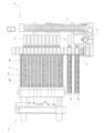
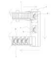
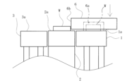
- a schematic diagram showing an overall outline of a centrifugal clutch assembly device Schematic diagram showing the weight sorting section of the centrifugal clutch assembly device A schematic plan view showing the positional relationship between the measuring means and the weight loading section in the weight sorting section.
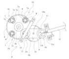
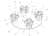
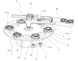
- Schematic diagram showing the spring assembly part of the centrifugal clutch assembly device A perspective view showing a weight placement means and a turntable for spring assembly in the spring assembly section.
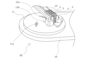
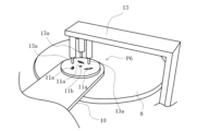
- a perspective view showing the spring assembly position in the spring assembly section A perspective view showing the state in which the weight is placed in the spring assembly section (before the spring is assembled) A perspective view showing the state in which the weight is placed in the spring assembly section (after the spring is assembled) A perspective view showing a transfer device between a spring assembly section and a weight assembly section of the centrifugal clutch assembly device.
- a perspective view showing the support plate assembly part of the centrifugal clutch assembly device A perspective view showing the holding means and shaft member supply means in the support plate assembly section.
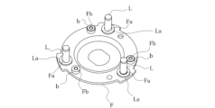
- a perspective view showing the weight assembly section of the centrifugal clutch assembly device A perspective view showing the side plate assembly part of the centrifugal clutch assembly device A perspective view showing the shaft member and damper assembled to the support plate in the support plate assembly section of the centrifugal clutch assembly device.
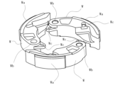
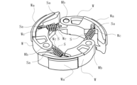
- a perspective view showing the centrifugal clutch (side plate side) assembled with the centrifugal clutch assembly device A perspective view showing the centrifugal clutch (support plate side) assembled by the centrifugal clutch assembly device
- the centrifugal clutch assembly device is for assembling a centrifugal clutch in which a weight W is swingably attached to a shaft member L formed on a support plate F, as shown in FIGS. 21 to 23.
- this device includes a weight sorting section A, a spring assembly section B, a support plate assembly section C, a weight assembly section D, and a side plate assembly section E. ing.
- the centrifugal clutch applied to this embodiment includes a support plate F to which a plurality of (three in this embodiment) shaft members L are attached, and each shaft member of the support plate F.
- a plurality of (three in this embodiment) weights W are inserted through and attached to L, a spring S is assembled by connecting adjacent weights W, and a spring S is assembled to the convex portion Fb of the support plate F.
- a side plate G is attached to the tip end of the shaft member L, and an E ring e is provided to prevent the weight W attached to the shaft member L from coming off.
- the support plate F is made of a metal annular member in which a plurality of (three in this embodiment) insertion holes Fa and convex portions Fb are formed in the circumferential direction, and a shaft member L is inserted into each insertion hole Fa. It is inserted through and fixed by caulking, and a damper b is attached to each convex portion Fb.
- the shaft member L is made of a shaft-like member having a flange La formed at a predetermined position, and the damper b is made of a rubber material or an elastic body formed into a cylindrical shape.
- the weight W is made of a metal member set to a predetermined weight, and has a clutch shoe Wa formed on its outer circumferential surface, an insertion hole Wb through which the shaft member L is inserted, and an end portion Sa of the spring S through which the weight W is inserted.
- An assembly recess Wc is formed.
- a plurality of such weights W (three in this embodiment) are arranged in an annular shape, and are assembled so as to be swingable about the shaft member L inserted through each through hole Wb.
- the spring S is made of a coil spring, and is assembled by inserting one end Sa and the other end Sa into the assembly recesses Wc of the adjacent weights W, and centrifugal force is generated to cause the weights W to swing outward.
- a biasing force is applied toward the initial position, and when the centrifugal force decreases, the biasing force causes the weight W to swing inward.
- the weight W is in the initial position, it is in contact with the damper b, and when the weight W swings outward, the swing is restricted, and when it swings inward, it is in contact with the damper b. It is designed to provide a buffer.
- the side plate G is made of a metal annular member assembled to face the support plate F, and has an insertion hole Ga through which the tip end of the shaft member L can be inserted.
- a weight W is attached between the support plate F and the side plate G so as to be able to swing freely relative to the shaft member L, and an E-ring e is attached to the tip end of the shaft member L to prevent it from coming off. It looks like this.
- this centrifugal clutch assembly device includes a weight sorting section A for sorting weights W, a spring assembly section B for assembling a spring S to the weight W, and a shaft member L for assembling a support plate F. It includes a support plate assembly section C, a weight assembly section D for assembling the weight W onto the support plate F, and a side plate assembly section E for assembling the side plate G.
- the weight sorting section A includes a first conveyor 1 as a weight carrying means, a measuring means 2 disposed at the terminal end of the first conveyor 1, and a starting end adjacent to the measuring means 2.
- a second conveyor 3 arranged substantially parallel to the first conveyor 1, a storage means 4 having a plurality of (10 in this embodiment) storage lanes 4a, and storage in each storage lane 4a of the storage means 4. It is equipped with a weight carrying-out means 5 capable of carrying out the weight W that has been carried out, and a control section J.
- the first conveyor 1 (weight carrying means) consists of a roller conveyor that can carry weights W in sequence, and the weights W are carried in starting from the left side in FIG. It is possible to convey it to the terminal end and convey it to the measuring means 2.
- the measuring means 2 consists of a weight measuring device that sequentially measures the weight of the weights W carried in by the first conveyor 1, and as shown in FIG. It is located between the department.
- this measuring means 2 has a placing surface 2a on which the weight W is placed when measuring weight, and the placing surface 2a is used to place the weight W on the first conveyor 1.
- the mounting surface 1a of the second conveyor 3 is set at approximately the same height as the mounting surface 3a on which the weight W is mounted.
- a weight transfer means 6 is provided for transferring the weight W carried in by the first conveyor 1 (weight carrying means) onto the mounting surface 2a of the measuring means 2. ing.
- the weight transfer means 6 is movable between the terminal end of the first conveyor 1 and the mounting surface 2a of the measurement means 2, and has an accommodation recess 6a in which the weight W can be accommodated and transferred. ing. When the weight W reaches the end of the first conveyor 1, the weight transfer means 6 descends to accommodate the weight W in the storage recess 6a (see FIG. 4), and the measurement is performed from the end of the first conveyor 1. By moving in parallel to the means 2 (see FIG. 5), the weight W is slid from the mounting surface 1a of the first conveyor 1 to the mounting surface 2a of the measuring means 2.
- the weight transfer means 6 can slide and transfer the weight W on the placement surface 1a of the first conveyor 1 onto the placement surface 2a of the measurement means 2, and perform measurement. It is configured so that the weight can be measured by means 2. Further, the weight W whose weight has been measured by the measuring means 2 is pressed by the weight transferring means 6 which moves in parallel from the terminal end of the first conveyor 1 to the measuring means 2, as shown in FIGS. It will slide to the starting end of 3.
- the second conveyor 3 consists of a roller conveyor that can sequentially convey the weights W whose weights have been measured by the measuring means 2.
- the second conveyor 3 sequentially conveys the weights W starting from the right side in FIG.
- a plurality of extrusion means g for selectively extruding and discharging heavy weights W are provided.
- the extrusion means g is disposed corresponding to the storage lane 4a of the storage means 4, and is configured to be selectively operated under the control of the control section J.
- the control unit J is composed of a computer having a storage, a microcomputer, etc., and is connected to the measuring means 2 to receive a signal related to the weight of the weight W measured by the measuring means 2, and to receive a signal related to the weight of the weight W measured by the measuring means 2.
- the upper limit and the lower limit of the allowable weight of the weight W are divided into fixed values, and it is set in advance that the weights W having weights within the range of each division are the weights W of the same weight.
- the upper limit and lower limit of the allowable weight are divided into 10 equal parts, and weights W having weights within the range of each division are determined to be weights W of the same weight. This is set by the control unit J.
- the weights W whose weights have been measured by the measuring means 2 are sequentially conveyed by the second conveyor 3, and are controlled by the control unit J so that weights of the same weight are pushed out and stored in the same storage lane 4a.
- the extrusion means g is selectively operated. Note that the weight W that falls outside the allowable weight is pushed out to the conveyance path m by the extrusion means g located upstream of the storage means 4, and is prevented from being accommodated by the storage means 4.
- the storage means 4 stores the weights W measured by the measurement means 2 by dividing them into the same weight, and stores a plurality of weights (10 in this embodiment) which classify and store the weights W by the same weight. It is configured to have a storage lane 4a.
- Each storage lane 4a is composed of a roller conveyor capable of conveying weights W separately from other storage lanes 4a, and can convey weights W selectively pushed out by extrusion means g toward weight delivery means 5. It is said that
- the weight carrying out means 5 is disposed at the terminal end side of each storage lane 4a (lower side in FIG. 2), and also carries weights W of the same weight divided by the storage means 4 (that is, weights W stored in each storage lane 4a).
- a predetermined number of weights W) are carried out from the storage means 4 to the spring assembly section B on the condition that the weights W) reach a predetermined number (in this embodiment, three, which is the number to be attached to the centrifugal clutch). It is something.
- the weight carrying out means 5 according to this embodiment is configured to carry out a predetermined number (3) of weights W arranged in an annular shape.
- the spring assembly section B consists of a device for assembling the springs S to the weights W carried out by the weight carrying means 5 and arranged in an annular shape, and as shown in FIG. It is configured to include an assembly turntable 8 and a spring assembly means 9.
- the weight placement means 7 includes a placement section 7a on which the three weights W are placed separately, and a drive source 7b such as a motor that moves the placement sections 7a away from or close to each other.
- a plurality (four in this embodiment) are provided on the same circumference in the spring assembly turntable 8.
- the spring assembly turntable 8 is rotatable around a rotation center 8a by a motor or the like (not shown), and its rotation moves the weight mounting means 7 from the mounting position P1 to the movement position P2 and from the mounting position P2 to the mounting position P2. It is possible to sequentially transport between position P3 and unloading position P4.
- the placing position P1 is a position where the weights W transported by the weight carrying means 5 are placed on the placing part 7a
- the moving position P2 is a position where the placing part 7a is moved by driving the drive source 7b. This is the position where the two parts are placed close to each other.
- the spring assembling means 9 assembles the spring S to the weight W placed on the placing part 7a of the weight placing means 7 located at the assembling position P3, and as shown in FIG.
- a moving member 10 rotatable around a center portion 10a, accommodating portions 11 attached to both ends of the moving member 10, a spring supplying means 12 for supplying a spring S, and a pushing means 13 for pushing the spring S into a weight W. It is equipped with.
- the moving member 10 is rotatable around a rotation center 10a by driving a motor or the like (not shown), and as shown in FIG. 8, accommodating portions 11 are formed at each end.
- Each accommodating portion 11 is rotatable around a rotation center portion 11b, and has a plurality of (three in this embodiment) accommodating holes 11a formed concentrically.
- the housing hole 11a is configured to have a shape corresponding to the spring S in its natural length state, and is capable of housing and holding the spring S supplied by the spring supply means 12 in its natural length state. There is.
- the spring S in the natural length state is received in the accommodating part 11 at one position P5 (see FIGS. 6 and 9), and the spring S in the natural length state
- the accommodating portion 11 can be alternately moved between the other position P6 (see FIGS. 6 and 10) where the spring S in the long state is assembled to the weight W.
- the spring S in its natural length state refers to the spring S in its uncompressed and unexpanded state.
- the spring supply means 12 is disposed near one position P5, and as shown in FIG. 9, the spring supply means 12 cuts and supplies the springs S one by one, and stores them in the housing part 11 that rotates around the rotation center part 11b.
- the springs S are sequentially inserted and housed in the holes 11a.
- the spring S accommodated in the accommodation hole 11a maintains its natural length and has its end Sa facing downward.
- the pushing means 13 is disposed near the other position P6, and the housing part 11 that accommodates the spring S is attached to the weight W placed on the weight placing means 7 (i.e., the weight placing means at the assembly position P3). 7), the spring S is assembled to the weight W by pushing it into the weight W while maintaining its natural length.
- the pushing means 13 includes a plurality of pushing parts 13a corresponding to the accommodation holes 11a, and when the pushing parts 13a descend, the springs in the accommodation holes 11a are released.
- the spring S is pushed downward and dropped, and the end Sa of the spring S is inserted into the assembly recess Wc of the weight W to be assembled, as shown in FIG.
- this transfer device 14 includes a clamping part 14a that clamps three weights W to which springs S are attached, and a clamping part that clamps the weights W by sliding along a sliding rail 14c.
- a moving body 14b for moving the weight assembly 14a to the weight assembly section D is provided.
- the support plate assembly section C consists of an assembly device for assembling the shaft member L and the damper b onto the support plate F, and as shown in FIGS. It is configured to include a table 15 and a holding means 16 capable of holding the shaft member L, the damper b, and the support plate F.
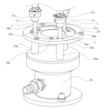
- the holding means 16 consists of a jig on which the shaft member L, the damper b, and the support plate F are mounted, and as shown in FIGS. 15 and 16, there are a plurality of jigs (in this embodiment, three A plurality of (three in this embodiment) holding holes 16a and a plurality of (three in this embodiment) recesses 16b for holding the damper b are formed.
- the turntable 15 for assembling the shaft member is made of a disc-shaped member in which a plurality of holding means 16 are formed in the circumferential direction, and is rotated by a motor (not shown) or the like to move the shaft member supply position Pa1 and the damper.
- the holding means 16 can be sequentially moved between a supply position Pa2, a support plate assembly position Pa3, a caulking position Pa4, an inspection position Pa5, and an unloading position Pa6.
- the shaft member supply position Pa1 is a position where the shaft member L is supplied by the shaft member supply means 17 and held by the holding means 16, and the shaft member L can be supplied to the holding means 16 at the shaft member supply position Pa1.
- a shaft member supply means 17 is provided.
- the shaft member supply means 17 includes a suction transfer means 17a that sucks the shaft member L and transfers it to the holding hole 16a of the holding means 16, and a holding hole of the holding means 16.
- a negative pressure generating means 18 capable of applying a negative pressure to 16a is provided.
- the suction transfer means 17a is made up of a suction pad or the like capable of suctioning a flange La formed at the upper end of the shaft member L, and is supported by a support portion 17b.
- This support portion 17b supports a plurality of (three in this embodiment) suction transfer means 17a and is movable along the sliding rail 17c. Further, the support part 17b is movable between a stock part (not shown) that accommodates a plurality of shaft members L and a shaft member supply position Pa1 by driving a drive source (not shown). After the shaft member L is attracted by the suction transfer means 17a, it can be transported to the shaft member supply position Pa1. That is, the shaft member L is conveyed to the shaft member supply position Pa1 while its flange La is attracted by the suction and transfer means 17a, and reaches a position above the holding hole 16a in the holding means 16.
- the negative pressure generating means 18 is composed of a negative pressure pump or the like capable of applying negative pressure to the holding hole 16a of the holding means 16, and as shown in FIGS. is connected to.
- the chamber portion 19 is formed of a cylindrical member having a hollow interior, and has a plurality of (three in this embodiment) connecting pipes 19a protruding from the chamber portion 19 and communicating with the interior space.
- the connecting pipe 19a is set to be connected to the lower part of the holding hole 16a.
- suction transfer means 17a is connected to a separate negative pressure generation means different from the negative pressure generation means 18 and adsorbs the shaft member L with the applied negative pressure, or is connected to the negative pressure generation means 18 and sucks the shaft member L with the applied negative pressure.
- the shaft member L may be attracted to the shaft member L using the negative pressure applied thereto.
- a supply device (not shown) is disposed at the damper supply position Pa2 for supplying the annular damper b and fitting it into the recess 16b of the holding means 16.
- a supply device (not shown) for supplying the support plate F to the holding means 16 is provided, and by supplying the support plate F to the holding means 16 with this device, the position shown in FIG. As shown in FIG. 3, while the shaft member L held in the holding hole 16a is inserted into the insertion hole Fa of the support plate F, the damper b fitted in the recess 16b is fitted into the convex portion Fb of the support plate F. It is designed to let you do so.
- a caulking device (not shown) is provided at the caulking position Pa4 to caulk and fix the upper end of the shaft member L inserted through the insertion hole Fa to the support plate F, and a caulking device (not shown) is provided at the inspection position Pa5.
- An inspection device (not shown) is provided to inspect the quality of the product. In this way, the support plate F to which the shaft member L is caulked and fixed reaches the carry-out position Pa6, and is carried out by the reversing carry-out means 20.
- the reversing and unloading means 20 is disposed between the unloading position Pa6 of the support plate assembly section C and the loading position Pb1 of the weight assembly section D, and holds the support plate F between them. It is equipped with a pair of clamping arms 20a.
- the support plate F to which the shaft member L is fixed reaches the unloading position Pa6, as shown in FIG.
- the support plate F held by the holding arm 20a is turned upside down and carried out to the carry-in position Pb1 of the weight assembly section D.
- the weight assembly part D is disposed adjacent to the spring assembly part B, as shown in FIG. 13, and is disposed adjacent to the support plate assembly part C, as shown in FIG.
- the weight assembling turntable 21 is rotatable around a center position, and a plurality of jigs 22 are attached to the weight assembling turntable 21 in a circumferential direction. It is configured.
- the weight assembly turntable 21 has a carry-in position Pb1 where the support plate F (support plate F to which the shaft member L is fixed) carried out from the support plate assembly part C is carried in, and a carry-in position Pb1 where the support plate F carried out from the support plate assembly part C (the support plate F to which the shaft member L is fixed) is carried in, and a carry-in position Pb1 where the support plate F carried out from the support plate assembly part C is carried in.
- an assembly position Pb2 where weights W are brought in and assembled on the support plate F
- an adjustment position Pb3 where the positions of the plurality of weights W are adjusted
- an unloading position Pb4 where the support plate F with the weights W assembled is taken out.
- the jig 22 can be sequentially moved between the two.
- the carry-in position Pb1 is a position where the support plate F, which has been attached with the shaft member L and the damper b in the support plate assembly section C and is carried out upside down and carried out by the inversion carry-out means 20, is carried in.
- the support plate F reaches the mounting position Pb2 by rotation of the weight mounting turntable 21. That is, as shown in FIG. 20, the support plate F carried into the carry-in position Pb1 is held on the jig 22 with the tip of the shaft member L facing upward, and then transported to the assembly position Pb2. becomes.
- the weight W which has been carried out with the spring S assembled in the spring assembly part B, is carried in, and during the carrying process, the shaft members L are inserted into the insertion holes Wb of the weights W, respectively. It is configured so that the weight W can be attached swingably.
- the adjustment position Pb3 is such that the relative positions of the three weights W placed on the jig 22 can be adjusted.
- the adjustment position Pb3 is the initial position when the weight W placed on the jig 22 contacts the damper b while avoiding interference with the damper b. It can be moved to the desired position.
- the support plate F with the weight W assembled at the predetermined position reaches the carry-out position Pb4 and is carried out by the carry-out means 23.
- the carrying-out means 23 has a plurality of clamping arms 23a formed at positions corresponding to the weights W, and supports the support plate F at the carrying-out position Pb4 of the weight assembly section D.
- the weight W can be held by the holding arms 23a and transported to the carry-in position Pc1 of the side plate assembly section E.
- the side plate assembly section E consists of an assembly device for the final process of assembling the side plates G to obtain a centrifugal clutch, and is arranged at a position adjacent to the weight assembly section D, as shown in FIG. At the same time, a side plate assembly turntable 24 rotatable around the center position, a pressing means 25, a carry-out conveyor 26, and a plurality of jigs attached over the circumferential direction of the side plate assembly turntable 24 are provided. 27.
- the side plate assembly turntable 24 has a carry-in position Pc1 for carrying in the support plate F (support plate F to which the weight W has been assembled) carried out from the weight assembly part D, and a side plate An assembly position Pc2 where the plate G is supplied and assembled, a retaining position Pc3 where the E-ring e is attached and the side plate G is prevented from coming off, an inspection position Pc4 where the installation state of the E-ring e is inspected, and The jig 27 can be sequentially moved between the unloading position Pc5 and the unloading position Pc5 where the centrifugal clutch is unloaded.
- the carry-in position Pc1 is a position where the support plate F to which the weight W is attached in the weight assembly part D and is carried out by the carry-out means 23 is carried in, and the carried-in support plate F is used for side plate assembly.
- the rotation of the turntable 24 brings it to the assembly position Pc2.
- the side plate G is supplied and the shaft member L fixed to the support plate F is inserted into the insertion hole Ga of the side plate G to be assembled.
- the retaining position Pc3 is provided with a retaining device (not shown) that prevents the side plate G from coming off by fitting an E ring e into each tip end side of the shaft member L inserted into the insertion hole Ga. There is.
- a centrifugal clutch as a product can be obtained by preventing the side plate G from coming off with the E-ring e in such a falling-off preventing device. Then, the centrifugal clutch with the E ring e attached at the retaining position Pc3 and the weight W attached between the support plate F and the side plate G moves to the inspection position Pc4 by the rotation of the side plate assembly turntable 24. Finally, the installation state of the E-ring e (whether or not it is installed, the orientation of the installation, whether the front and back sides are correct, etc.) is inspected.
- the centrifugal clutch inspected at the inspection position Pc4 reaches the unloading position Pc5 by further rotation of the side plate assembly turntable 24, and the pressing means 25 is activated, so that the centrifugal clutch at the unloading position Pc5 moves to the unloading conveyor. 26 and are carried out one by one.
- the final product, the centrifugal clutch can be automatically assembled.
- the weight sorting section A automatically sorts the weights W
- the spring assembly section B automatically attaches the spring S
- the support plate assembly section C automatically attaches the support plate.
- Automatic assembly of the shaft member L to the shaft member F, automatic assembly of the weight W to the shaft member L of the support plate F by the weight assembly section D, automatic assembly of the side plate G by the side plate assembly section E. centrifugal clutches can be manufactured automatically.
- the weight mounting means 7 places the weights W arranged in an annular shape, and the spring assembly that assembles the spring S to the weight W placed on the weight mounting means 7
- the weight mounting means 7 can place the weight W while positioning it at a position where the spring S can be assembled with the spring S at its natural length, thereby simplifying the assembly work of the centrifugal clutch. Automation can be achieved, and the spring S can be easily assembled to the weight W.
- the spring assembly means 9 includes a moving member 10 in which an accommodating portion 11 capable of accommodating the spring S in a state of natural length is formed, and an accommodating portion 11 that accommodates the spring S as a weight mounting means.
- a moving member 10 in which an accommodating portion 11 capable of accommodating the spring S in a state of natural length is formed, and an accommodating portion 11 that accommodates the spring S as a weight mounting means.
- the movable member 10 has housing parts 11 attached to both ends thereof, and has one position where the spring S in the natural length state is received in the housing part 11 and a spring S stored in the housing part 11. Since the accommodating portion 11 can be alternately moved between the long spring S and the other position where the spring S is attached to the weight W, the spring S can be quickly attached to the weight W. It is possible to shorten the takt time when assembling the spring.
- the weight mounting means 7 has a mounting position P1 where the weight W is mounted by rotating the spring assembly turntable 8, and the spring S is assembled by the spring assembly means 9. Since it is possible to sequentially move between the assembly position P3 where the spring S is attached and the carry-out position P4 where the weight W with the spring S attached is carried out, the spring S for the weight W is moved using the spring assembly turntable 8. can be assembled smoothly and quickly.
- the present invention is not limited thereto, and for example, an assembly device that does not use the turntable 8 for spring assembly may be used, or a moving member 10 having a housing portion 11 or a pushing means 13 may be used.
- the spring S may be assembled to the weight W using a different means.
- the weight selection section A automatically sorts out the weights W
- the support plate assembly section C automatically attaches the shaft member L to the support plate F.
- the weight W is automatically assembled to the shaft member L of the support plate F by the weight assembly part D
- the side plate G is automatically assembled by the side plate assembly part E.
- the work may be done manually.
- centrifugal clutch assembly device has the same meaning as the present invention, it can also be applied to devices that have a different external shape or have other functions added.
Landscapes
- Engineering & Computer Science (AREA)
- Mechanical Engineering (AREA)
- General Engineering & Computer Science (AREA)
- Automatic Assembly (AREA)
- Specific Conveyance Elements (AREA)
- One-Way And Automatic Clutches, And Combinations Of Different Clutches (AREA)
- Testing Of Balance (AREA)
Abstract
Description
本実施形態に係る遠心クラッチ組付け装置は、図21~23に示すように、支持プレートFに形成された軸部材Lに対してウェイトWが揺動可能に取り付けられた遠心クラッチを組付けるための装置であり、図1に示すように、ウェイト選別部Aと、スプリング組付け部Bと、支持プレート組付け部Cと、ウェイト組付け部Dと、サイドプレート組付け部Eとを具備している。
2 計測手段
3 第2コンベア
4 収容手段
4a 収容レーン
5 ウェイト搬出手段
6 ウェイト移送手段
7 ウェイト載置手段
7a 載置部
7b 駆動源
8 スプリング組付け用ターンテーブル
8a 回転中心部
9 スプリング組付け手段
10 移動部材
10a 回転中心部
11 収容部
11a 収容孔
11b 回転中心部
12 スプリング供給手段
13 押し込み手段
13a 押し込み部
14 移送装置
14a 挟持部
14b 移動体
14c 摺動レール
15 軸部材組付け用ターンテーブル
16 保持手段
16a 保持孔
16b 凹部
17 軸部材供給手段
17a 吸着移送手段
17b 支持部
17c 摺動レール
18 負圧発生手段
19 チャンバ部
20 反転搬出手段
20a 挟持アーム
20b 回転軸
21 ウェイト組付け用ターンテーブル
22 治具
23 搬出手段
23a 挟持アーム
24 サイドプレート組付け用ターンテーブル
25 押圧手段
26 搬出コンベア
27 治具
A ウェイト選別部
B スプリング組付け部
C 支持プレート組付け部
D ウェイト組付け部
E サイドプレート組付け部
W ウェイト
Wa クラッチシュー
Wb 挿通孔
Wc 組付け凹部
S スプリング
L 軸部材
F 支持プレート
Fa 挿通孔
Fb 凸部
G サイドプレート
e Eリング
b ダンパ
J 制御部
Claims (5)
- 支持プレートに形成された軸部材に対してウェイトが揺動可能に取り付けられた遠心クラッチを組付けるための遠心クラッチ組付け装置であって、
前記ウェイトを円環状に並べた状態で載置させるウェイト載置手段と、
前記ウェイト載置手段に載置された前記ウェイトにスプリングを組付けるスプリング組付け手段と、
を具備するとともに、前記ウェイト載置手段は、前記スプリングを自然長の状態で組付け可能な位置に前記ウェイトを位置決めしつつ載置可能とされたことを特徴とする遠心クラッチ組付け装置。 - 前記スプリング組付け手段は、
自然長の状態の前記スプリングを収容可能な収容部が形成された移動部材と、
前記スプリングを収容した収容部が前記ウェイト載置手段に載置された前記ウェイトの上方に位置するとき、自然長の状態を維持しつつ前記スプリングを前記ウェイトに押し込んで組付ける押し込み手段と、
を具備することを特徴とする請求項1記載の遠心クラッチ組付け装置。 - 前記移動部材は、その両端に前記収容部がそれぞれ取り付けられるとともに、自然長の状態の前記スプリングを前記収容部に受け入れる一方の位置と、前記収容部に収容された自然長の状態の前記スプリングを前記ウェイトに組付ける他方の位置との間を当該収容部が交互に移動可能とされたことを特徴とする請求項2記載の遠心クラッチ組付け装置。
- 前記ウェイト載置手段が複数設けられたスプリング組付け用ターンテーブルを有するとともに、当該ウェイト載置手段は、前記スプリング組付け用ターンテーブルが回転することにより、前記ウェイトを載置する載置位置と、前記スプリング組付け手段により前記スプリングを組付ける組付け位置と、前記スプリングが組付けられた前記ウェイトを搬出する搬出位置との間を順次移動可能とされたことを特徴とする請求項1記載の遠心クラッチ組付け装置。
- 前記スプリング組付け手段で前記スプリングが組付けられた前記ウェイトを前記支持プレートに形成された軸部材に組付けるウェイト組付け部を有したことを特徴とする請求項1記載の遠心クラッチ組付け装置。
Priority Applications (1)
| Application Number | Priority Date | Filing Date | Title |
|---|---|---|---|
| CN202380053719.9A CN119546868A (zh) | 2022-09-01 | 2023-08-30 | 离心式离合器组装设备 |
Applications Claiming Priority (2)
| Application Number | Priority Date | Filing Date | Title |
|---|---|---|---|
| JP2022-139530 | 2022-09-01 | ||
| JP2022139530A JP7268235B1 (ja) | 2022-09-01 | 2022-09-01 | 遠心クラッチ組付け装置 |
Publications (1)
| Publication Number | Publication Date |
|---|---|
| WO2024048677A1 true WO2024048677A1 (ja) | 2024-03-07 |
Family
ID=86270065
Family Applications (1)
| Application Number | Title | Priority Date | Filing Date |
|---|---|---|---|
| PCT/JP2023/031617 Ceased WO2024048677A1 (ja) | 2022-09-01 | 2023-08-30 | 遠心クラッチ組付け装置 |
Country Status (3)
| Country | Link |
|---|---|
| JP (1) | JP7268235B1 (ja) |
| CN (1) | CN119546868A (ja) |
| WO (1) | WO2024048677A1 (ja) |
Families Citing this family (4)
| Publication number | Priority date | Publication date | Assignee | Title |
|---|---|---|---|---|
| JP7498944B2 (ja) * | 2020-06-23 | 2024-06-13 | 株式会社大一商会 | 遊技機 |
| JP7498945B2 (ja) * | 2020-06-23 | 2024-06-13 | 株式会社大一商会 | 遊技機 |
| JP7502759B2 (ja) * | 2020-06-23 | 2024-06-19 | 株式会社大一商会 | 遊技機 |
| JP7502758B2 (ja) * | 2020-06-23 | 2024-06-19 | 株式会社大一商会 | 遊技機 |
Citations (2)
| Publication number | Priority date | Publication date | Assignee | Title |
|---|---|---|---|---|
| CN102806462A (zh) * | 2012-08-31 | 2012-12-05 | 浙江派尼尔机电有限公司 | 一种离合器装配装置 |
| JP2015203429A (ja) * | 2014-04-11 | 2015-11-16 | 株式会社エフ・シー・シー | 遠心クラッチ |
-
2022
- 2022-09-01 JP JP2022139530A patent/JP7268235B1/ja active Active
-
2023
- 2023-08-30 CN CN202380053719.9A patent/CN119546868A/zh active Pending
- 2023-08-30 WO PCT/JP2023/031617 patent/WO2024048677A1/ja not_active Ceased
Patent Citations (2)
| Publication number | Priority date | Publication date | Assignee | Title |
|---|---|---|---|---|
| CN102806462A (zh) * | 2012-08-31 | 2012-12-05 | 浙江派尼尔机电有限公司 | 一种离合器装配装置 |
| JP2015203429A (ja) * | 2014-04-11 | 2015-11-16 | 株式会社エフ・シー・シー | 遠心クラッチ |
Also Published As
| Publication number | Publication date |
|---|---|
| CN119546868A (zh) | 2025-02-28 |
| JP2024034947A (ja) | 2024-03-13 |
| JP7268235B1 (ja) | 2023-05-02 |
Similar Documents
| Publication | Publication Date | Title |
|---|---|---|
| WO2024048677A1 (ja) | 遠心クラッチ組付け装置 | |
| JP6537668B2 (ja) | フレキシブルな組み立て機械、システムおよび方法 | |
| JP4006580B2 (ja) | モータの組立装置 | |
| WO2024048679A1 (ja) | 遠心クラッチ組付け装置 | |
| RU2008133242A (ru) | Способ и аппаратура для сборки комплексного изделия в параллельной системе подготовки продукции | |
| CN112846752B (zh) | 电机壳组装机中磁瓦、卡簧压入装置 | |
| WO2024048678A1 (ja) | 遠心クラッチ組付け装置 | |
| JP2006281355A (ja) | 精密部品の組み立てシステムおよびそのための精密部品の組み立て装置 | |
| WO2024048676A1 (ja) | 遠心クラッチ組付け装置 | |
| CN214024465U (zh) | 汽车发动机链条张紧器全自动组装设备 | |
| CN215010001U (zh) | 电机壳组装机的朝向定位装置 | |
| CN118635880A (zh) | 一种打火机自动装配设备 | |
| CN117896974A (zh) | 一种自动贴装设备 | |
| CN113851344B (zh) | 一种柱上开关生产线 | |
| CN113245837B (zh) | 基于转盘的上料工位及转盘装置 | |
| CN214979137U (zh) | 电机壳组装机的进料装置 | |
| JP2604690B2 (ja) | フランジ自動組付け溶接装置及びフランジ自動組付け溶接方法 | |
| CN117444609B (zh) | 一种装配设备 | |
| CN109396639B (zh) | 夹具、夹持系统、焊接系统及焊接方法 | |
| CN112719834A (zh) | 电机壳组装机的二级推送装置 | |
| CN223044062U (zh) | 自动化隔离卡装配生产线 | |
| CN120887189B (zh) | 一种制动器蹄块加工用运送设备 | |
| US20250367970A1 (en) | Wheel Assembly System and Method | |
| JPS63207704A (ja) | 車両用ホイ−ルのバランスウエイト取付装置 | |
| CN217833235U (zh) | 一种用于工件组装的浮动机构 |
Legal Events
| Date | Code | Title | Description |
|---|---|---|---|
| 121 | Ep: the epo has been informed by wipo that ep was designated in this application |
Ref document number: 23860439 Country of ref document: EP Kind code of ref document: A1 |
|
| WWE | Wipo information: entry into national phase |
Ref document number: 202380053719.9 Country of ref document: CN |
|
| WWE | Wipo information: entry into national phase |
Ref document number: 202517007854 Country of ref document: IN |
|
| WWE | Wipo information: entry into national phase |
Ref document number: 2501000674 Country of ref document: TH |
|
| WWP | Wipo information: published in national office |
Ref document number: 202380053719.9 Country of ref document: CN |
|
| WWP | Wipo information: published in national office |
Ref document number: 202517007854 Country of ref document: IN |
|
| NENP | Non-entry into the national phase |
Ref country code: DE |
|
| 122 | Ep: pct application non-entry in european phase |
Ref document number: 23860439 Country of ref document: EP Kind code of ref document: A1 |