WO2024048672A1 - 被覆工具および切削工具 - Google Patents
被覆工具および切削工具 Download PDFInfo
- Publication number
- WO2024048672A1 WO2024048672A1 PCT/JP2023/031600 JP2023031600W WO2024048672A1 WO 2024048672 A1 WO2024048672 A1 WO 2024048672A1 JP 2023031600 W JP2023031600 W JP 2023031600W WO 2024048672 A1 WO2024048672 A1 WO 2024048672A1
- Authority
- WO
- WIPO (PCT)
- Prior art keywords
- ratio
- film
- coating layer
- layer
- compound
- Prior art date
- Legal status (The legal status is an assumption and is not a legal conclusion. Google has not performed a legal analysis and makes no representation as to the accuracy of the status listed.)
- Ceased
Links
Images


Classifications
-
- C—CHEMISTRY; METALLURGY
- C23—COATING METALLIC MATERIAL; COATING MATERIAL WITH METALLIC MATERIAL; CHEMICAL SURFACE TREATMENT; DIFFUSION TREATMENT OF METALLIC MATERIAL; COATING BY VACUUM EVAPORATION, BY SPUTTERING, BY ION IMPLANTATION OR BY CHEMICAL VAPOUR DEPOSITION, IN GENERAL; INHIBITING CORROSION OF METALLIC MATERIAL OR INCRUSTATION IN GENERAL
- C23C—COATING METALLIC MATERIAL; COATING MATERIAL WITH METALLIC MATERIAL; SURFACE TREATMENT OF METALLIC MATERIAL BY DIFFUSION INTO THE SURFACE, BY CHEMICAL CONVERSION OR SUBSTITUTION; COATING BY VACUUM EVAPORATION, BY SPUTTERING, BY ION IMPLANTATION OR BY CHEMICAL VAPOUR DEPOSITION, IN GENERAL
- C23C14/00—Coating by vacuum evaporation, by sputtering or by ion implantation of the coating forming material
- C23C14/02—Pretreatment of the material to be coated
- C23C14/024—Deposition of sublayers, e.g. to promote adhesion of the coating
-
- B—PERFORMING OPERATIONS; TRANSPORTING
- B23—MACHINE TOOLS; METAL-WORKING NOT OTHERWISE PROVIDED FOR
- B23B—TURNING; BORING
- B23B27/00—Tools for turning or boring machines; Tools of a similar kind in general; Accessories therefor
- B23B27/14—Cutting tools of which the bits or tips or cutting inserts are of special material
- B23B27/148—Composition of the cutting inserts
-
- B—PERFORMING OPERATIONS; TRANSPORTING
- B23—MACHINE TOOLS; METAL-WORKING NOT OTHERWISE PROVIDED FOR
- B23B—TURNING; BORING
- B23B51/00—Tools for drilling machines
-
- B—PERFORMING OPERATIONS; TRANSPORTING
- B23—MACHINE TOOLS; METAL-WORKING NOT OTHERWISE PROVIDED FOR
- B23C—MILLING
- B23C5/00—Milling-cutters
- B23C5/16—Milling-cutters characterised by physical features other than shape
-
- B—PERFORMING OPERATIONS; TRANSPORTING
- B23—MACHINE TOOLS; METAL-WORKING NOT OTHERWISE PROVIDED FOR
- B23P—METAL-WORKING NOT OTHERWISE PROVIDED FOR; COMBINED OPERATIONS; UNIVERSAL MACHINE TOOLS
- B23P15/00—Making specific metal objects by operations not covered by a single other subclass or a group in this subclass
- B23P15/28—Making specific metal objects by operations not covered by a single other subclass or a group in this subclass cutting tools
-
- C—CHEMISTRY; METALLURGY
- C23—COATING METALLIC MATERIAL; COATING MATERIAL WITH METALLIC MATERIAL; CHEMICAL SURFACE TREATMENT; DIFFUSION TREATMENT OF METALLIC MATERIAL; COATING BY VACUUM EVAPORATION, BY SPUTTERING, BY ION IMPLANTATION OR BY CHEMICAL VAPOUR DEPOSITION, IN GENERAL; INHIBITING CORROSION OF METALLIC MATERIAL OR INCRUSTATION IN GENERAL
- C23C—COATING METALLIC MATERIAL; COATING MATERIAL WITH METALLIC MATERIAL; SURFACE TREATMENT OF METALLIC MATERIAL BY DIFFUSION INTO THE SURFACE, BY CHEMICAL CONVERSION OR SUBSTITUTION; COATING BY VACUUM EVAPORATION, BY SPUTTERING, BY ION IMPLANTATION OR BY CHEMICAL VAPOUR DEPOSITION, IN GENERAL
- C23C14/00—Coating by vacuum evaporation, by sputtering or by ion implantation of the coating forming material
- C23C14/06—Coating by vacuum evaporation, by sputtering or by ion implantation of the coating forming material characterised by the coating material
- C23C14/0641—Nitrides
Definitions
- the present disclosure relates to coated tools and cutting tools.
- Coated tools which have improved wear resistance by coating the surface of a base material such as cemented carbide, cermet, or ceramics with a coating layer, are known as tools used for cutting processes such as turning or milling. ing.
- a coated tool includes a base, a first coating layer located on the base, a second coating layer located on the first coating layer, and a second coating layer located on the second coating layer. and a third coating layer located at.
- the first coating layer contains Al, Ti, Cr, and N.
- the second coating layer includes a first film and a second film.
- the first film contains Al, Ti, Cr, and N, and has a Ti/Al ratio higher than the Ti/Al ratio in the first coating layer.
- the second film contains Al, Ti, Cr, and N, and has a higher Cr/Al ratio than the Cr/Al ratio in the first coating layer.
- the third coating layer includes a third film and a fourth film.
- the third film contains Al, Ti, Cr, and N, and has a Ti/Al ratio higher than that of the first film.
- the fourth film contains Al, Ti, Cr, and N, and has a higher Cr/Al ratio than the Cr/Al ratio in the second film.
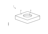
- FIG. 1 is a perspective view showing an example of a coated tool according to an embodiment.
- FIG. 2 is a side sectional view showing an example of the coated tool according to the embodiment.
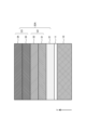
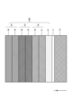
- FIG. 3 is a cross-sectional view showing an example of the coating layer according to the first embodiment.
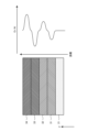
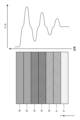
- FIG. 4A is a schematic diagram illustrating the Ti/Al ratio in the coating layer according to the first embodiment.
- FIG. 4B is a schematic diagram illustrating the Cr/Al ratio in the coating layer according to the first embodiment.
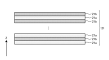
- FIG. 5A is a cross-sectional view showing an example of a first covering layer included in the covering layer according to the first embodiment.
- FIG. 5B is a cross-sectional view showing an example of the second coating layer included in the coating layer according to the first embodiment.
- FIG. 5C is a cross-sectional view showing an example of a third coating layer included in the coating layer according to the first embodiment.
- FIG. 6 is a cross-sectional view showing an example of the coating layer according to the second embodiment.
- FIG. 7A is a schematic diagram illustrating the Ti/Al ratio in the coating layer according to the second embodiment.
- FIG. 7B is a schematic diagram illustrating the Cr/Al ratio in the coating layer according to the second embodiment.
- FIG. 8 is a cross-sectional view showing an example of a fourth coating layer included in the coating layer according to the second embodiment.
- FIG. 9 is a diagram schematically showing an example of a film forming apparatus for forming a coating layer on a substrate.
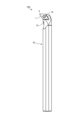
- FIG. 10 is a front view showing an example of the cutting tool according to the embodiment.
- Coated tools which have improved wear resistance by coating the surface of a base material such as cemented carbide, cermet, or ceramics with a coating layer, are known as tools used for cutting processes such as turning or milling. ing.
- FIG. 1 is a perspective view showing an example of a coated tool according to an embodiment.
- FIG. 2 is a side sectional view showing an example of the coated tool according to the embodiment.
- the coated tool 1 according to the embodiment has a tip body 2.
- FIG. 1 is a perspective view showing an example of a coated tool according to an embodiment.
- FIG. 2 is a side sectional view showing an example of the coated tool according to the embodiment.
- the coated tool 1 according to the embodiment has a tip body 2.
- FIG. 1 is a perspective view showing an example of a coated tool according to an embodiment.
- FIG. 2 is a side sectional view showing an example of the coated tool according to the embodiment.
- the coated tool 1 according to the embodiment has a tip body 2.
- FIG. 1 is a perspective view showing an example of a coated tool according to an embodiment.
- FIG. 2 is a side sectional view showing an example of the coated tool according to the embodiment.
- the coated tool 1 according to the embodiment has a tip body 2.
- Chip body 2 has, for example, a hexahedral shape in which the top surface and the bottom surface (the surface intersecting the Z axis shown in FIG. 1) are parallelograms.
- the cutting edge has a first surface (for example, an upper surface) and a second surface (for example, a side surface) connected to the first surface.
- the first surface functions as a "rake surface” that scoops up chips generated by cutting
- the second surface functions as a "relief surface.”
- a cutting blade is located on at least a portion of the ridgeline where the first surface and the second surface intersect, and the coated tool 1 cuts the workpiece by applying the cutting blade to the workpiece.
- a through hole 5 that vertically passes through the chip body 2 is located in the center of the chip body 2.
- a screw 75 for attaching the covered tool 1 to a holder 70, which will be described later, is inserted into the through hole 5 (see FIG. 10).
- the chip body 2 has a base 10 and a covering layer 20.
- the base body 10 is made of cemented carbide, for example.
- the cemented carbide contains W (tungsten), specifically, WC (tungsten carbide).
- the cemented carbide may contain Ni (nickel) or Co (cobalt).
- the base body 10 is made of a WC-based cemented carbide having WC particles as a hard phase component and Co as a main binder phase component.
- the base body 10 may be formed of cermet.
- the cermet contains, for example, Ti (titanium), specifically TiC (titanium carbide) or TiN (titanium nitride).
- the cermet may contain Ni or Co.
- the base body 10 may be formed of a cubic boron nitride sintered body containing cubic boron nitride (cBN) particles.
- the substrate 10 is not limited to cubic boron nitride (cBN) particles, but may also contain particles such as hexagonal boron nitride (hBN), rhombohedral boron nitride (rBN), or wurtzite boron nitride (wBN). good.
- the base body 10 may be made of ceramics.
- ceramics include Al 2 O 3 (aluminum oxide).
- Examples of the types of Al 2 O 3 include ⁇ -Al 2 O 3 and ⁇ -Al 2 O 3 .
- Ceramics may contain other elements in aluminum oxide.
- ceramics in addition to aluminum oxide, ceramics contain at least one of magnesium (Mg), calcium (Ca), strontium (Sr), silicon (Si), and a Group 3 element of the periodic table. Good too.
- the coating layer 20 is coated on the base body 10 for the purpose of improving the wear resistance, heat resistance, etc. of the base body 10, for example.
- a covering layer 20 completely covers the substrate 10.
- the covering layer 20 is located at least on the base 10 .
- the coating layer 20 is located on the first surface (here, the upper surface) of the base 10, the first surface has high wear resistance and high heat resistance.
- the coating layer 20 is located on the second surface (here, the side surface) of the base 10, the second surface has high wear resistance and high heat resistance.
- FIG. 3 is a cross-sectional view showing an example of the coating layer according to the first embodiment.
- FIG. 4A is a schematic diagram illustrating the Ti/Al ratio in the coating layer according to the first embodiment.
- FIG. 4B is a schematic diagram illustrating the Cr/Al ratio in the coating layer according to the first embodiment.
- FIG. 5A is a cross-sectional view showing an example of a first covering layer included in the covering layer according to the first embodiment.
- FIG. 5B is a cross-sectional view showing an example of the second coating layer included in the coating layer according to the first embodiment.
- FIG. 5C is a cross-sectional view showing an example of a third coating layer included in the coating layer according to the first embodiment.
- the covering layer 20A according to the first embodiment as the covering layer 20 includes a first covering layer 21 located on the base 10 and a covering layer 20A located on the first covering layer 21. It includes a second covering layer 22 and a third covering layer 23 located on the second covering layer 22.
- the chip body 2 includes an intermediate layer 11 in addition to the base 10 and the covering layer 20A as the covering layer 20, as shown in FIG. located between.
- the first covering layer 21 is located on the base body 10 via the intermediate layer 11.
- the first coating layer 21 contains Al, Ti, Cr, and N.
- the first covering layer 21 may be, for example, an AlTiCrN layer containing AlTiCrN, which is a nitride of Al, Ti, and Cr.
- AlTiCrN means that Al, Ti, Cr, and N are present in an arbitrary ratio, and Al, Ti, Cr, and N are not necessarily present in a 1:1:1:1 ratio. It does not mean that.
- the thickness of the first coating layer 21 is, for example, 500 nm or more and 1500 nm or less.
- the first coating layer 21 located on the base 10 is a coating layer located on the base 10 and the first coating layer 21 (in the coating layer 20A, the second coating layer 22 and the third coating layer 23) It is possible to reduce the residual stress between. That is, the first coating layer 21 can reduce residual stress between the base body 10 and the coating layer 20A. Thereby, peeling or cracking between the base body 10 and the coating layer 20A can be reduced. In other words, the adhesion between the base 10 and the coating layer 20A can be improved. As a result, the life of the coated tool 1 can be extended.
- the second coating layer 22 includes a first film 31 and a second film 32, as shown in FIG.
- Each of the first film 31 and the second film 32 contains Al, Ti, Cr, and N.
- Each of the first film 31 and the second film 32 may be, for example, an AlTiCrN film containing AlTiCrN, which is a nitride of Al, Ti, and Cr.
- the thickness of the first film 31 is, for example, 200 nm or more and 400 nm or less.
- the thickness of the second film 32 is, for example, 200 nm or more and 400 nm or less.
- the first film 31 has a Ti/Al ratio higher than the Ti/Al ratio in the first coating layer 21.
- the Ti/Al ratio means the ratio of the number of Ti atoms to the number of Al atoms.
- the coating layer 20A can be used without significantly increasing the residual stress between the base body 10 and the coating layer located on the second coating layer 22 (in the coating layer 20A, the third coating layer 23). can improve the wear resistance and chipping resistance of
- the first film 31 may have a Cr/Al ratio lower than the Cr/Al ratio in the first coating layer 21.
- the second film 32 has a higher Cr/Al ratio than the Cr/Al ratio in the first coating layer 21.
- the Cr/Al ratio means the ratio of the number of Cr atoms to the number of Al atoms.
- the coating layer 20A can be used without significantly increasing the residual stress between the base body 10 and the coating layer located on the second coating layer 22 (in the coating layer 20A, the third coating layer 23). can improve the lubricity and welding resistance of
- the second film 32 may have a lower Ti/Al ratio than the Ti/Al ratio in the first coating layer 21.
- the second coating layer 22 improves the wear resistance and chipping resistance of the coating layer 20A without significantly increasing the residual stress between the base body 10 and the coating layer located on the second coating layer 22. At the same time, the lubricity and welding resistance of the coating layer 20A can be improved. As a result, the life of the coated tool 1 can be extended.
- the third coating layer 23 includes a third film 33 and a fourth film 34, as shown in FIG.
- Each of the third film 33 and the fourth film 34 contains Al, Ti, Cr, and N.
- Each of the third film 33 and the fourth film 34 may be, for example, an AlTiCrN film containing AlTiCrN, which is a nitride of Al, Ti, and Cr.
- the thickness of the third film 33 is, for example, 200 nm or more and 400 nm or less.
- the thickness of the fourth film 34 is, for example, 200 nm or more and 400 nm or less.
- the third film 33 has a higher Ti/Al ratio than the Ti/Al ratio in the first film 31.
- the Ti/Al ratio means the ratio of the number of Ti atoms to the number of Al atoms. Thereby, the wear resistance and chipping resistance of the coating layer 20A can be improved.
- the third film 33 may have a lower Cr/Al ratio than the Cr/Al ratio in the first film 31.
- the fourth film 34 has a higher Cr/Al ratio than the Cr/Al ratio in the second film 32.
- the Cr/Al ratio means the ratio of the number of Cr atoms to the number of Al atoms. Thereby, the lubricity and welding resistance of the coating layer 20A can be improved.
- the fourth film 34 may have a lower Ti/Al ratio than the Ti/Al ratio in the second film 32.
- the third coating layer 23 can improve the wear resistance and chipping resistance of the coating layer 20A, as well as the lubricity and welding resistance of the coating layer 20A. As a result, the life of the coated tool 1 can be extended.
- the Ti/Al ratio in the covering layer 20A may change continuously in the thickness direction of the covering layer 20A.
- the average value of the Ti/Al ratio in this region may be taken as the Ti/Al ratio in this region.
- the Ti/Al ratio in the covering layer 20A is approximately constant in the first covering layer 21.
- the Ti/Al ratio in the covering layer 20A is maximum in the first film 31 included in the second covering layer 22 and the third film 33 included in the third covering layer 23.
- the Ti/Al ratio in the covering layer 20A is minimal in the second film 32 included in the second covering layer 22 and the fourth film 34 included in the third covering layer 23.
- the Ti/Al ratio in the first film 31 larger than the Ti/Al ratio in the first coating layer 21, but also the maximum value of the Ti/Al ratio in the first film 31 is larger than the Ti/Al ratio in the first coating layer 21.
- the Ti/Al ratio may be larger than the Ti/Al ratio in the coating layer 21.
- the Ti/Al ratio in the third film 33 larger than the Ti/Al ratio in the first film 31, but also the maximum value of the Ti/Al ratio in the third film 33 is higher than the Ti/Al ratio in the first film 31.
- /Al ratio may be larger than the maximum value.
- Ti/Al ratio in the second film 32 is smaller than the Ti/Al ratio in the first coating layer 21, but also the minimum value of the Ti/Al ratio in the second film 32 is smaller than that in the first coating layer 21.
- the Ti/Al ratio may be smaller than the Ti/Al ratio in .
- the Ti/Al ratio in the fourth film 34 is smaller than the Ti/Al ratio in the second film 32, but also the minimum value of the Ti/Al ratio in the fourth film 34 is lower than the Ti/Al ratio in the second film 32.
- /Al ratio may be smaller than the minimum value.
- the Cr/Al ratio in the covering layer 20A may change continuously in the thickness direction of the covering layer 20A.
- the average value of the Cr/Al ratio in this region may be taken as the Cr/Al ratio in this region.
- the Cr/Al ratio in the covering layer 20A is approximately constant in the first covering layer 21.
- the Cr/Al ratio in the covering layer 20A is maximum in the second film 32 included in the second covering layer 22 and the fourth film 34 included in the third covering layer 23.
- the Cr/Al ratio in the covering layer 20A is minimal in the first film 31 included in the second covering layer 22 and the third film 33 included in the third covering layer 23.
- the Cr/Al ratio in the second film 32 is larger than the Cr/Al ratio in the first coating layer 21, but also the maximum value of the Cr/Al ratio in the second film 32 is higher than that in the first coating layer 21.
- the Cr/Al ratio may be greater than the Cr/Al ratio in the coating layer 21.
- the Cr/Al ratio in the fourth film 34 is greater than the Cr/Al ratio in the second film 32, but the maximum value of the Cr/Al ratio in the fourth film 34 is greater than the Cr/Al ratio in the second film 32.
- /Al ratio may be larger than the maximum value.
- the Cr/Al ratio in the first film 31 is smaller than the Cr/Al ratio in the first coating layer 21, but also the minimum value of the Cr/Al ratio in the first film 31 is smaller than the Cr/Al ratio in the first coating layer 21.
- the Cr/Al ratio may be smaller than the Cr/Al ratio.
- the Cr/Al ratio in the third film 33 is smaller than the Cr/Al ratio in the first film 31, but also the minimum value of the Cr/Al ratio in the third film 33 is lower than the Cr/Al ratio in the first film 31.
- /Al ratio may be smaller than the minimum value.
- the covering layer 20A is shown in which the first covering layer 21, the first film 31, the second film 32, the third film 33, and the fourth film 34 are laminated in this order on the base 10,
- the first coating layer 21, the second film 32, the first film 31, the fourth film 34, and the third film 33 may be laminated in this order.
- the first covering layer 21 may include a region in which a plurality of compound layers 21a and a plurality of compound layers 21b are alternately stacked.
- the Ti/Al ratio and Cr/Al ratio in the compound layer 21a are different from the Ti/Al ratio and Cr/Al ratio in the compound layer 21b, respectively.
- the Ti/Al ratio in the compound layer 21a is larger than the Ti/Al ratio in the compound layer 21b
- the Cr/Al ratio in the compound layer 21b is larger than the Cr/Al ratio in the compound layer 21a.
- the average thickness of each of the compound layer 21a and the compound layer 21b is 1 nm or more and 10 nm or less.
- the hardness of the first coating layer 21 can be improved.
- the strength of the first coating layer 21 can be improved.
- the life of the coated tool 1 can be extended.
- the first film 31 included in the second covering layer 22 may include a region in which a plurality of compound layers 31a and a plurality of compound layers 31b are alternately stacked.
- the Ti/Al ratio and Cr/Al ratio in the compound layer 31a are different from the Ti/Al ratio and Cr/Al ratio in the compound layer 31b, respectively.
- the Ti/Al ratio in the compound layer 31a is larger than the Ti/Al ratio in the compound layer 31b
- the Cr/Al ratio in the compound layer 31b is larger than the Cr/Al ratio in the compound layer 31a.
- the average thickness of each of the compound layer 31a and the compound layer 31b is 1 nm or more and 10 nm or less.
- the hardness of the first film 31 and the hardness of the second coating layer 22 can be improved accordingly.
- the strength of the first film 31 and the strength of the second coating layer 22 can be improved accordingly.
- the life of the coated tool 1 can be extended.
- the second film 32 included in the second coating layer 22 may include a region in which a plurality of compound layers 32a and a plurality of compound layers 32b are alternately stacked.
- the Ti/Al ratio and Cr/Al ratio in the compound layer 32a are different from the Ti/Al ratio and Cr/Al ratio in the compound layer 32b, respectively.
- the Cr/Al ratio in the compound layer 32a is greater than the Cr/Al ratio in the compound layer 32b
- the Ti/Al ratio in the compound layer 32b is greater than the Ti/Al ratio in the compound layer 32a.
- the average thickness of each of the compound layer 32a and the compound layer 32b is 1 nm or more and 10 nm or less.
- the hardness of the second film 32 and the hardness of the second coating layer 22 can be improved accordingly.
- the strength of the second film 32 and the strength of the second coating layer 22 can be improved accordingly.
- the life of the coated tool 1 can be extended.
- the third film 33 included in the third coating layer 23 may include a region in which a plurality of compound layers 33a and a plurality of compound layers 33b are alternately stacked.
- the Ti/Al ratio and Cr/Al ratio in the compound layer 33a are different from the Ti/Al ratio and Cr/Al ratio in the compound layer 33b, respectively.
- the Ti/Al ratio in the compound layer 33a is larger than the Ti/Al ratio in the compound layer 33b
- the Cr/Al ratio in the compound layer 33b is larger than the Cr/Al ratio in the compound layer 33a.
- the average thickness of each of the compound layer 33a and the compound layer 33b is 1 nm or more and 10 nm or less.
- the hardness of the third film 33 and the hardness of the third coating layer 23 can be improved accordingly.
- the strength of the third film 33 and the strength of the third coating layer 23 can be improved accordingly.
- the life of the coated tool 1 can be extended.
- the fourth film 34 included in the third covering layer 23 may include a region in which a plurality of compound layers 34a and a plurality of compound layers 34b are alternately stacked.
- the Ti/Al ratio and Cr/Al ratio in the compound layer 34a are different from the Ti/Al ratio and Cr/Al ratio in the compound layer 34b, respectively.
- the Cr/Al ratio in the compound layer 34a is greater than the Cr/Al ratio in the compound layer 34b
- the Ti/Al ratio in the compound layer 34b is greater than the Ti/Al ratio in the compound layer 34a.
- the average thickness of each of the compound layer 34a and the compound layer 34b is 1 nm or more and 10 nm or less.
- the hardness of the fourth film 34 and the hardness of the third coating layer 23 can be improved accordingly.
- the strength of the fourth film 34 and the strength of the third coating layer 23 can be improved accordingly.
- the life of the coated tool 1 can be extended.
- the ratio of elements in the coating layer or film contained in the coating layer 20A can be determined by, for example, an analysis based on X-ray photoelectron spectroscopy (XPS) or an energy dispersive X-ray spectrometer attached to a scanning transmission electron microscope (STEM). It can be identified by analysis using EDS).
- XPS X-ray photoelectron spectroscopy
- STEM scanning transmission electron microscope
- EDS energy dispersive X-ray spectrometer attached to a scanning transmission electron microscope
- an intermediate layer 11 may be located between the base 10 and the covering layer 20A as the covering layer 20. Specifically, the intermediate layer 11 is in contact with the upper surface of the base 10 on one surface (here, the lower surface), and in contact with the coating layer 20A (for example, the first coating layer 21) on the other surface (here, the upper surface). touches the bottom surface of
- the intermediate layer 11 has higher adhesion to the base 10 than the covering layer 20A.
- metal elements having such characteristics include Zr, Hf, V, Nb, Ta, Cr, Mo, W, Al, Si, Y, and Ti.
- the intermediate layer 11 contains at least one metal element among the above metal elements.
- the intermediate layer 11 may contain Ti.
- Si is a metalloid element, in this specification, metalloid elements are also included in metal elements.
- the content rate of Ti in the intermediate layer 11 may be 1.5 atomic % or more.
- the Ti content in the intermediate layer 11 may be 2 atomic % or more.
- the intermediate layer 11 may contain components other than the above metal elements (Zr, Hf, V, Nb, Ta, Cr, Mo, W, Al, Si, Y, and Ti). However, from the viewpoint of adhesion to the base 10, the intermediate layer 11 may contain at least 95 atomic % or more of the above metal elements in total. The intermediate layer 11 may contain the above metal elements in a total amount of 98 atomic % or more. The proportion of the metal component in the intermediate layer 11 can be determined, for example, by analysis using an energy dispersive X-ray spectrometer (EDS) attached to a scanning transmission electron microscope (STEM).
- EDS energy dispersive X-ray spectrometer
- STEM scanning transmission electron microscope
- the intermediate layer 11 which has higher wettability with the substrate 10 than the coating layer 20A, between the substrate 10 and the coating layer 20A, it is possible to improve the adhesion between the substrate 10 and the coating layer 20A. can. Since the intermediate layer 11 has high adhesion to the coating layer 20A, peeling of the coating layer 20A from the intermediate layer 11 is unlikely to occur.
- the thickness of the intermediate layer 11 may be, for example, 0.1 nm or more and less than 20 nm.
- FIG. 6 is a cross-sectional view showing an example of the coating layer according to the second embodiment.
- FIG. 7A is a schematic diagram illustrating the Ti/Al ratio in the coating layer according to the second embodiment.
- FIG. 7B is a schematic diagram illustrating the Cr/Al ratio in the coating layer according to the second embodiment.
- FIG. 8 is a cross-sectional view showing an example of a fourth coating layer included in the coating layer according to the second embodiment.
- the coating layer 20B according to the second embodiment further includes a fourth coating layer 24 located on the third coating layer 23. It differs from the coating layer 20A according to the first embodiment in that it includes the coating layer 20A. Description of the structure of the covering layer 20B according to the second embodiment, which is similar to the structure of the covering layer 20A according to the first embodiment, will be omitted.
- the fourth coating layer 24 includes a fifth film 35 and a sixth film 36, as shown in FIG.
- the fifth film 35 contains Al, Ti, and N.
- the fifth film 35 may be, for example, an AlTiN film containing AlTiN, which is a nitride of Al and Ti.
- AlTiN means that Al, Ti, and N are present in an arbitrary ratio, and does not necessarily mean that Al, Ti, and N are present in a 1:1:1 ratio. do not have.
- the fifth film 35 may further contain Cr.
- the fifth film 35 may be, for example, an AlTiCrN film containing AlTiCrN, which is a nitride of Al, Ti, and Cr.
- the thickness of the fifth film 35 is, for example, 200 nm or more and 400 nm or less.
- the sixth film 36 contains Al, Cr, and N.
- the sixth film 36 may be, for example, an AlCrN film containing AlCrN, which is a nitride of Al and Cr.
- AlCrN means that Al, Cr, and N are present in an arbitrary ratio, and does not necessarily mean that Al, Cr, and N are present in a 1:1:1 ratio. do not have.
- the sixth film 36 may further contain Ti.
- the sixth film 36 may be, for example, an AlTiCrN film containing AlTiCrN, which is a nitride of Al, Ti, and Cr.
- the thickness of the sixth film 36 is, for example, 200 nm or more and 400 nm or less.
- the fifth film 35 has a higher Ti/Al ratio than the Ti/Al ratio in the third film 33.
- the Ti/Al ratio means the ratio of the number of Ti atoms to the number of Al atoms. Thereby, the wear resistance and chipping resistance of the coating layer 20B can be further improved.
- the fifth film 35 may have a lower Cr/Al ratio than the Cr/Al ratio in the third film 33.
- the sixth film 36 has a higher Cr/Al ratio than the Cr/Al ratio in the fourth film 34.
- the Cr/Al ratio means the ratio of the number of Cr atoms to the number of Al atoms. Thereby, the lubricity and welding resistance of the coating layer 20B can be further improved.
- the sixth film 36 may have a lower Ti/Al ratio than the Ti/Al ratio in the fourth film 34.
- the fourth coating layer 24 can further improve the wear resistance and chipping resistance of the coating layer 20B, and further improve the lubricity and welding resistance of the coating layer 20A. As a result, the life of the coated tool 1 can be further extended.
- the third coating layer 23 is formed so as not to significantly increase the residual stress between the base 10 and the fourth coating layer 24 as a coating layer located on the third coating layer 23. act.
- the Ti/Al ratio in the fifth film 35 may be 1 or more and 1.5 or less.
- the wear resistance and chipping resistance of the coating layer 20B can be further improved.
- the Ti/Al ratio in the fifth film 35 is 1.5 or less, residual stress between the base 10 and the coating layer 20B can be prevented from increasing significantly. Thereby, peeling or cracking between the base body 10 and the coating layer 20B can be reduced. As a result, the life of the coated tool 1 can be further extended.
- the Cr/Al ratio in the sixth film 36 may be 1 or more and 1.5 or less.
- the Cr/Al ratio in the sixth film 36 is 1 or more, the lubricity and welding resistance of the coating layer 20B can be further improved.
- the Cr/Al ratio in the sixth film 36 is 1.5 or less, residual stress between the base 10 and the coating layer 20B can be prevented from increasing significantly. Thereby, peeling or cracking between the base body 10 and the coating layer 20B can be reduced. As a result, the life of the coated tool 1 can be further extended.
- the Ti/Al ratio in the covering layer 20B may change continuously in the thickness direction of the covering layer 20B.
- the average value of the Ti/Al ratio in this region may be taken as the Ti/Al ratio in this region.
- the Ti/Al ratio in the covering layer 20B is also maximum in the fifth film 35 included in the fourth covering layer 24.
- the Ti/Al ratio in the covering layer 20B is also minimal in the sixth film 36 included in the fourth covering layer 24.
- the maximum value of the Ti/Al ratio in the fifth film 35 is larger than the maximum value of the Ti/Al ratio in the third film 33.
- the minimum value of the Ti/Al ratio in the sixth film 36 is smaller than the minimum value of the Ti/Al ratio in the fourth film 34.
- the minimum value of the Ti/Al ratio in the sixth film 36 is, for example, substantially zero.
- the Cr/Al ratio in the covering layer 20B may change continuously in the thickness direction of the covering layer 20B.
- the average value of the Cr/Al ratio in this region may be taken as the Cr/Al ratio in this region.
- the Cr/Al ratio in the covering layer 20B is also maximum in the sixth film 36 included in the fourth covering layer 24.
- the Cr/Al ratio in the covering layer 20B is also minimal in the fifth film 35 included in the fourth covering layer 24.
- the maximum value of the Cr/Al ratio in the sixth film 36 is larger than the maximum value of the Cr/Al ratio in the fourth film 34.
- the minimum value of the Cr/Al ratio in the fifth film 35 is smaller than the minimum value of the Cr/Al ratio in the third film 33.
- the minimum value of the Cr/Al ratio in the fifth film 35 is, for example, substantially zero.
- a first coating layer 21, a first film 31, a second film 32, a third film 33, a fourth film 34, a fifth film 35, and a sixth film 36 are laminated in order on the base 10.
- the fifth films 35 may be stacked in order.
- the fifth film 35 included in the fourth coating layer 24 may include a region in which a plurality of compound layers 35a and a plurality of compound layers 35b are alternately stacked.
- the Ti/Al ratio in the compound layer 35a is different from the Ti/Al ratio in the compound layer 35b.
- the Ti/Al ratio in the compound layer 35a is greater than the Ti/Al ratio in the compound layer 35b.
- the average thickness of each of the compound layer 35a and the compound layer 35b is 1 nm or more and 10 nm or less.
- the hardness of the fifth film 35 and the hardness of the fourth coating layer 24 can be improved accordingly.
- the hardness of the fourth coating layer 24 at high temperatures can be improved.
- the strength of the fifth film 35 and the strength of the fourth coating layer 24 can be improved accordingly.
- the wear resistance of the fourth coating layer 24 can be improved. As a result, the life of the coated tool 1 can be further extended.
- the sixth film 36 included in the fourth covering layer 24 may include a region in which a plurality of compound layers 36a and a plurality of compound layers 36b are alternately stacked.
- the Cr/Al ratio in the compound layer 36a is different from the Cr/Al ratio in the compound layer 36b.
- the Cr/Al ratio in the compound layer 36a is greater than the Cr/Al ratio in the compound layer 36b.
- the average thickness of each of the compound layer 36a and the compound layer 36b is 1 nm or more and 10 nm or less.
- the hardness of the sixth film 36 and the hardness of the fourth coating layer 24 can be improved accordingly.
- the hardness of the fourth coating layer 24 at high temperatures can be improved.
- the strength of the sixth film 36 and the strength of the fourth coating layer 24 can be improved accordingly.
- the wear resistance of the fourth coating layer 24 can be improved. As a result, the life of the coated tool 1 can be further extended.
- FIG. 9 is a diagram schematically showing an example of a film forming apparatus for forming a coating layer on a substrate.
- the method for manufacturing the coated tool 1 is not limited to the method shown below.
- a base body 10 having the shape of the coated tool 1 is produced using a conventionally known method.
- a coating layer 20 is formed on the surface of the base 10.
- a method for forming the coating layer 20 for example, a physical vapor deposition (PVD) method such as an ion plating method or a sputtering method can be used.
- PVD physical vapor deposition
- an arc ion plating film forming apparatus hereinafter referred to as an AIP apparatus 1000 as shown in FIG. 9 can be used, for example.
- the AIP device 1000 shown in FIG. 9 introduces a gas such as N 2 or Ar into a vacuum chamber 101 from a gas inlet 102, and creates a high temperature gap between a cathode electrode 103 and an anode electrode 104 arranged in the AIP device 1000.
- a voltage is applied to generate a gas plasma.
- Such plasma evaporates and ionizes the desired metal or ceramic from the target 105 to generate metal or ceramic ions in a high energy state.
- This ionized metal or ceramic is attached to the surface of the base 10 as a sample, and the surface of the base 10 is coated with the coating layer 20 .
- a plurality of substrates 10 may be set on the tower 107 and placed on the sample support stand 106.
- a plurality of sample support stands 106 (two sets in the figure) may be placed on a table (not shown).
- a heater 108 for heating the base 10 a gas exhaust port 109 for discharging gas out of the system, and a bias power supply 110 for applying a bias voltage to the base 10 are provided. ing.
- a metal target containing metal aluminum (Al), metal titanium (Ti), and metal chromium (Cr) each independently, an alloy target that is a composite of these, a powder of these nitrides, or A mixture target made of a sintered body can be used.
- a first alloy target that is a composite of Al and Ti, and a second alloy target that is a composite of Al and Cr can be used.
- the metal source is evaporated by arc discharge or glow discharge, and the metal of the metal source is ionized, and at the same time, the metal of the metal source is reacted with nitrogen (N 2 ) gas of the nitrogen source, so that the surface of the base 10 is A covering layer 20 is deposited on.
- the sample support stand 106 is controlled so that the distance from the position of the target 105 to the position of the base 10 is 160 mm or more, for example, 260 mm or more.
- a large number of highly straight lines of magnetic force are generated from the center of the surface of the target 105 toward the base 10, and the magnetic flux density near the base 10 is set to 0.2 to 0.8 mT (millitesla).
- Nitrogen gas may be introduced into the AIP apparatus 1000 as a reaction gas to create an atmospheric pressure of 2 to 10 Pa.
- the temperature of the substrate 10 is maintained at 300 to 500°C.
- a bias voltage of -50 to -200 V is applied to the base 10, and an arc discharge of 30 to 200 A is generated between the target 105 (cathode electrode 103) and the anode electrode 104.
- metal is deposited on the base 10 while rotating and revolving the base 10.
- the current value of the arc discharge generated between the target 105 as the cathode electrode 103 and the anode electrode 104 is controlled.
- the current value of the arc discharge generated between the anode electrode 104 and a first alloy target made of a composite of Al and Ti or a second alloy target made of a composite of Al and Cr as the cathode electrode 103 is controlled. .
- the first alloy target that is a composite of Al and Ti as the cathode electrode 103 and the anode electrode 104.
- the Cr/Al ratio in the coating layer or film included in the coating layer 20 it is necessary to combine a second alloy target that is a composite of Al and Cr as the cathode electrode 103 and the anode electrode 104. Increase (or decrease) the current value of the arc discharge generated during the process.
- an electromagnetic coil or a permanent magnet as a magnetic field generation source is installed around the target 105, or a permanent magnet is placed inside the AIP device 1000, for example, in the center.
- the magnetic field can be controlled by adjusting the position of adjacent targets 105.
- the magnetic force is calculated by measuring the magnetic flux density at the position of the base 10 using a magnetic flux density meter.
- the magnetic flux density is expressed in the unit mT (millitesla).
- the distance from the position of the target 105 to the position of the base 10 represents the distance measured at the position where the base 10 is closest to the target 105 and the distance where the base 10 is farthest from the target 105.
- the rotation speed of the sample is set to the period in which the substrate 10 approaches the target 105 at each position on the substrate 10 as shown in FIG.
- the period of the difference in the composition of heavy metals and light metals in the thickness direction of 20 can be adjusted.
- the rotational speeds of the base 10 and the sample support 106 may be adjusted to have a period of 2 to 20 rpm (rotations per minute).
- each of the sample supports 106 on which the substrate 10 is placed rotates while the tower 107 rotates, and the table may also be rotated so that the plurality of sample supports 106 revolve.
- the time or distance that metal ions fly from the target 105 to the base 10 can be adjusted. Thereby, it is also possible to differentiate the compositions of heavy metal components and light metal components during film formation.
- the base body 10 is arranged so that the base body 10 approaches and faces the target 105, heavy metal components from the target 105 will fly straight to the base body 10, and the amount of heavy metals will be larger than that of light metals. It is deposited on the substrate 10.
- the base body 10 is arranged so that the base body 10 is away from the target 105 and does not face the target 105, it is thought that the amount of heavy metal components deposited decreases because the light metal components go around and are deposited on the base body 10.
- FIG. 10 is a front view showing an example of the cutting tool according to the embodiment.
- a cutting tool 100 includes a covered tool 1 and a holder 70 for fixing the covered tool 1.
- the holder 70 is a rod-shaped member that extends from a first end (upper end in FIG. 10) toward a second end (lower end in FIG. 10).
- the holder 70 is made of steel or cast iron, for example. In particular, steel with high toughness may be used among these members.
- the holder 70 has a pocket 73 at the first end.
- the pocket 73 is a portion on which the coated tool 1 is mounted, and has a seating surface that intersects with the rotational direction of the workpiece, and a restraining side surface that is inclined with respect to the seating surface.
- the seating surface is provided with a screw hole into which a screw 75 (described later) is screwed.
- the covered tool 1 is located in the pocket 73 of the holder 70 and is attached to the holder 70 by screws 75. That is, the screw 75 is inserted into the through hole 5 of the covered tool 1, and the tip of the screw 75 is inserted into a screw hole formed in the seating surface of the pocket 73, so that the screw portions are screwed together. Thereby, the coated tool 1 is attached to the holder 70 such that the cutting edge portion 3 protrudes outward from the holder 70.
- a cutting tool used for so-called turning is exemplified.
- turning processing include inner diameter processing, outer diameter processing, and grooving.
- the cutting tool is not limited to those used for turning.
- the coated tool 1 may be used as a cutting tool used for milling.
- Cutting tools used for milling include milling cutters such as flat milling cutters, face milling cutters, side milling cutters, and groove milling cutters, as well as single-flute end mills, multi-flute end mills, tapered blade end mills, and ball end mills. Examples include end mills.
- a coated tool according to the example was produced by forming a coating layer on a base made of WC-based cemented carbide using an AIP apparatus as shown in FIG.
- targets a first alloy target made of a composite of Al and Ti, and a second alloy target made of a composite of Al and Cr were used.
- a coating layer was deposited on the substrate by reacting metal ions generated from the first alloy target or the second alloy target with nitrogen gas.
- the current value of the arc discharge generated between the first alloy target or the second alloy target as the cathode electrode and the anode electrode is as follows. It was controlled as follows.
- the current value of the arc discharge generated between the first alloy target and the anode electrode is set to 200A
- the current value of the arc discharge generated between the second alloy target and the anode electrode is set to 200A.
- the current value of the arc discharge generated between the first alloy target and the anode electrode is set to 100A, and the current value of the arc discharge generated between the second alloy target and the anode electrode is set to 50A.
- the first film included in the second coating layer was laminated on the first coating layer.
- the current value of the arc discharge generated between the first metal target and the anode electrode is set to 50A, and the current value of the arc discharge generated between the second metal target and the anode electrode is set to 100A.
- the second film included in the second coating layer was laminated on the first film.
- the current value of the arc discharge generated between the first alloy target and the anode electrode is set to 120A, and the current value of the arc discharge generated between the second alloy target and the anode electrode is set to 30A.
- the third film included in the third coating layer was laminated on the second film.
- the current value of the arc discharge generated between the first alloy target and the anode electrode is set to 30A, and the current value of the arc discharge generated between the second alloy target and the anode electrode is set to 120A.
- the fourth film included in the third coating layer was laminated on the third film.
- the current value of the arc discharge generated between the first alloy target and the anode electrode is set to 150A, and the current value of the arc discharge generated between the second alloy target and the anode electrode is set to 0A.
- the fifth film included in the fourth coating layer was laminated on the fourth film.
- the current value of the arc discharge generated between the first alloy target and the anode electrode is set to 0A, and the current value of the arc discharge generated between the second alloy target and the anode electrode is set to 150A.
- the sixth film included in the third coating layer was laminated on the fifth film.
- the elements contained in the coating layer or film deposited on the substrate were analyzed by X-ray photoelectron spectroscopy (XPS).
- Each of the first coating layer, the first film and the second film included in the second coating layer, and the third film and the fourth film included in the third coating layer are made of Al and Ti. It was confirmed that it contained Cr, N, and Cr. It was confirmed that the fifth film included in the fourth coating layer contained Al, Ti, and N. It was confirmed that the sixth film included in the fourth coating layer contained Al, Cr, and N.
- the Ti/Al ratio in the first coating layer, first film, second film, third film, fourth film, fifth film, and sixth film is the thickness of the coating layer or film. It was confirmed that in the direction of , that is, in the direction perpendicular to the surface of the substrate, it changes continuously with respect to the distance from the surface of the substrate.
- the Cr/Al ratio in the first coating layer, first film, second film, third film, fourth film, fifth film, and sixth film is the thickness of the coating layer or film. It was confirmed that in the direction of , that is, in the direction perpendicular to the surface of the substrate, it changes continuously with respect to the distance from the surface of the substrate.
- Elemental analysis was performed on the fifth film and the sixth film using an energy dispersive X-ray spectrometer (EDS).
- EDS energy dispersive X-ray spectrometer
- a bright-field image and a high-angle scattering annular dark-field image obtained by scanning transmission electron microscopy (STEM) were obtained for the fifth film and the sixth film.
- the fifth film includes a region in which a plurality of first compound layers and a plurality of second compound layers are alternately laminated
- the sixth film includes a region in which a plurality of third compound layers and a plurality of second compound layers are stacked alternately. It could be confirmed that the sample contained a region in which the compound layers No. 4 and 4 were alternately stacked.
- the Ti/Al ratio in the first compound layer is different from the Ti/Al ratio in the second compound layer
- the Cr/Al ratio in the third compound layer is different from the Cr/Al ratio in the fourth compound layer. I was able to confirm that.
- Cutting tests were conducted on coated tools according to Examples and coated tools according to conventional products (Conventional Product 1, Conventional Product 2, and Conventional Product 3) as comparative examples.
- the test conditions for the cutting test were as follows. A cutting test was conducted under the following conditions using a carbide grade for drilling (model number: 2ZDK060-HP-OH (internal oil supply type) ⁇ 6 mm) as a substrate.
- Cutting method Drilling
- Work material S50C
- Cutting speed Vc 100m/min
- Feed amount per rotation f 0.13mm/rev
- Axial depth of cut H 12mm
- Machining type Wet method
- Evaluation method Drilling is performed on the base under the above conditions, and the maximum wear amount (mm) of the cutting edge of the coated tool is calculated for the number of holes formed in the workpiece. It was measured. The maximum amount of wear on the cutting edge was defined as the maximum depth from the flank surface of the cutting edge to the part where wear was observed.
- Table 1 shows the maximum wear amount of the cutting edge of the coated tool according to the example and the coated tools according to the conventional products (conventional product 1, conventional product 2, conventional product 3) with respect to the number of holes formed in the workpiece.
- the maximum wear amount of the cutting edge of the coated tool according to the example with respect to the number of holes formed in the work material is the same as that of the conventional products (conventional product 1, This is smaller than the maximum wear amount of the cutting edge of the coated tool related to Conventional Product 2 and Conventional Product 3). Therefore, when comparing the coated tool according to the example with the coated tool according to the conventional products (conventional product 1, conventional product 2, conventional product 3), it is found that the coated tool according to the example improves the wear resistance of the coated tool. I was able to confirm that it is possible.
- the coated tool (for example, coated tool 1) according to the embodiment includes a base body (for example, base body 10) and a first coating layer (for example, first coating layer) located on the base body. coating layer 21), a second coating layer (for example, second coating layer 22) located on the first coating layer, and a third coating layer (22) located on the second coating layer. As an example, a third coating layer 23) is provided.
- the first coating layer contains Al, Ti, Cr, and N.
- the second coating layer includes a first film (for example, first film 31) and a second film (for example, second film 32).
- the first film contains Al, Ti, Cr, and N, and has a Ti/Al ratio higher than the Ti/Al ratio in the first coating layer.
- the second film contains Al, Ti, Cr, and N, and has a higher Cr/Al ratio than the Cr/Al ratio in the first coating layer.
- the third coating layer includes a third film (for example, the third film 33) and a fourth film (for example, the fourth film 34).
- the third film contains Al, Ti, Cr, and N, and has a Ti/Al ratio higher than that of the first film.
- the fourth film contains Al, Ti, Cr, and N, and has a higher Cr/Al ratio than the Cr/Al ratio in the second film.
- the life of the tool can be extended.
- a coated tool according to the present disclosure includes, for example, a rod-shaped main body having a rotating shaft and extending from a first end to a second end, a cutting blade located at the first end of the main body, and a second end of the main body from the cutting blade. It may have a groove extending spirally toward the side.
- a base body a first coating layer located on the substrate; a second coating layer located on the first coating layer; a third coating layer located on the second coating layer;
- the first coating layer contains Al, Ti, Cr and N
- the second coating layer is a first film containing Al, Ti, Cr and N and having a Ti/Al ratio higher than the Ti/Al ratio in the first coating layer; a second film containing Al, Ti, Cr and N and having a Cr/Al ratio higher than the Cr/Al ratio in the first coating layer;
- the third coating layer is a third film containing Al, Ti, Cr and N and having a Ti/Al ratio higher than the Ti/Al ratio in the first film; a fourth film containing Al, Ti, Cr and N and having a Cr/Al ratio higher than the Cr/Al ratio in the second film; Coated tools.
- Additional note (2) The maximum value of the Ti/Al ratio in the third film is larger than the maximum value of the Ti/Al ratio in the first film.
- the coated tool described in appendix (1) Additional note (3): The minimum value of the Ti/Al ratio in the fourth film is smaller than the minimum value of the Ti/Al ratio in the second film.
- Additional note (4) further comprising a fourth coating layer located on the third coating layer,
- the fourth coating layer is a fifth film containing Al, Ti and N and having a Ti/Al ratio higher than the Ti/Al ratio in the third film; a sixth film containing Al, Cr and N and having a Cr/Al ratio higher than the Cr/Al ratio in the fourth film;
- the coated tool according to any one of appendices (1) to (3).
- the fifth film includes a region in which a plurality of first compound layers and a plurality of second compound layers are alternately stacked,
- the sixth film includes a region in which a plurality of third compound layers and a plurality of fourth compound layers are alternately laminated,
- the Ti/Al ratio in the first compound layer is different from the Ti/Al ratio in the second compound layer
- the Cr/Al ratio in the third compound layer is different from the Cr/Al ratio in the fourth compound layer.
- the Ti/Al ratio in the first compound layer is larger than the Ti/Al ratio in the second compound layer,
- the Cr/Al ratio in the third compound layer is larger than the Cr/Al ratio in the fourth compound layer.
- Additional note (8) a rod-shaped holder with a pocket at the end; and the coated tool according to any one of appendices (1) to (7), located in the pocket
Landscapes
- Chemical & Material Sciences (AREA)
- Engineering & Computer Science (AREA)
- Mechanical Engineering (AREA)
- Chemical Kinetics & Catalysis (AREA)
- Materials Engineering (AREA)
- Metallurgy (AREA)
- Organic Chemistry (AREA)
- Cutting Tools, Boring Holders, And Turrets (AREA)
- Physical Vapour Deposition (AREA)
Priority Applications (4)
| Application Number | Priority Date | Filing Date | Title |
|---|---|---|---|
| JP2024544345A JP7850815B2 (ja) | 2022-08-31 | 2023-08-30 | 被覆工具および切削工具 |
| KR1020257003669A KR20250034438A (ko) | 2022-08-31 | 2023-08-30 | 피복 공구 및 절삭 공구 |
| DE112023003591.1T DE112023003591T5 (de) | 2022-08-31 | 2023-08-30 | Beschichtetes werkzeug und schneidwerkzeug |
| CN202380058026.9A CN119585066A (zh) | 2022-08-31 | 2023-08-30 | 涂层刀具以及切削刀具 |
Applications Claiming Priority (2)
| Application Number | Priority Date | Filing Date | Title |
|---|---|---|---|
| JP2022-138710 | 2022-08-31 | ||
| JP2022138710 | 2022-08-31 |
Publications (1)
| Publication Number | Publication Date |
|---|---|
| WO2024048672A1 true WO2024048672A1 (ja) | 2024-03-07 |
Family
ID=90099783
Family Applications (1)
| Application Number | Title | Priority Date | Filing Date |
|---|---|---|---|
| PCT/JP2023/031600 Ceased WO2024048672A1 (ja) | 2022-08-31 | 2023-08-30 | 被覆工具および切削工具 |
Country Status (5)
| Country | Link |
|---|---|
| JP (1) | JP7850815B2 (https=) |
| KR (1) | KR20250034438A (https=) |
| CN (1) | CN119585066A (https=) |
| DE (1) | DE112023003591T5 (https=) |
| WO (1) | WO2024048672A1 (https=) |
Citations (5)
| Publication number | Priority date | Publication date | Assignee | Title |
|---|---|---|---|---|
| JP2003340607A (ja) * | 2002-05-27 | 2003-12-02 | Mitsubishi Materials Corp | 高速重切削条件で硬質被覆層がすぐれた耐チッピング性を発揮する表面被覆超硬合金製切削工具 |
| CN102975418A (zh) * | 2012-12-20 | 2013-03-20 | 上海壳瑞微材料科技有限公司 | 一种pcb用超硬耐磨铬基复合涂层微钻及其制备方法 |
| JP2018039045A (ja) * | 2016-09-07 | 2018-03-15 | 和田山精機株式会社 | 被覆冷間用金型 |
| CN107815638A (zh) * | 2017-11-07 | 2018-03-20 | 福建工程学院 | 一种含有多层结构的AlTiCrCN纳米硬质涂层及其制备方法 |
| CN112846335A (zh) * | 2021-01-07 | 2021-05-28 | 湖南博云东方粉末冶金有限公司 | 一种用于钢轨铣削刀片的涂层 |
Family Cites Families (7)
| Publication number | Priority date | Publication date | Assignee | Title |
|---|---|---|---|---|
| JP3969230B2 (ja) | 2002-07-24 | 2007-09-05 | 三菱マテリアル株式会社 | 重切削加工条件で硬質被覆層がすぐれた耐チッピング性を発揮する表面被覆超硬合金製切削工具 |
| JP5261981B2 (ja) * | 2007-05-17 | 2013-08-14 | 日立ツール株式会社 | 被覆切削工具 |
| JP5331210B2 (ja) * | 2009-11-12 | 2013-10-30 | オーエスジー株式会社 | 硬質被膜、および硬質被膜被覆工具 |
| JP5975339B2 (ja) * | 2012-10-16 | 2016-08-23 | 三菱マテリアル株式会社 | 表面被覆切削工具 |
| JP2018030212A (ja) | 2016-08-25 | 2018-03-01 | 三菱マテリアル株式会社 | 耐チッピング性と耐摩耗性にすぐれた表面被覆切削工具 |
| JP2023002267A (ja) * | 2021-06-22 | 2023-01-10 | Seavac株式会社 | 硬質皮膜 |
| WO2023157466A1 (ja) * | 2022-02-15 | 2023-08-24 | Seavac株式会社 | 硬質皮膜 |
-
2023
- 2023-08-30 CN CN202380058026.9A patent/CN119585066A/zh active Pending
- 2023-08-30 DE DE112023003591.1T patent/DE112023003591T5/de active Pending
- 2023-08-30 JP JP2024544345A patent/JP7850815B2/ja active Active
- 2023-08-30 WO PCT/JP2023/031600 patent/WO2024048672A1/ja not_active Ceased
- 2023-08-30 KR KR1020257003669A patent/KR20250034438A/ko active Pending
Patent Citations (5)
| Publication number | Priority date | Publication date | Assignee | Title |
|---|---|---|---|---|
| JP2003340607A (ja) * | 2002-05-27 | 2003-12-02 | Mitsubishi Materials Corp | 高速重切削条件で硬質被覆層がすぐれた耐チッピング性を発揮する表面被覆超硬合金製切削工具 |
| CN102975418A (zh) * | 2012-12-20 | 2013-03-20 | 上海壳瑞微材料科技有限公司 | 一种pcb用超硬耐磨铬基复合涂层微钻及其制备方法 |
| JP2018039045A (ja) * | 2016-09-07 | 2018-03-15 | 和田山精機株式会社 | 被覆冷間用金型 |
| CN107815638A (zh) * | 2017-11-07 | 2018-03-20 | 福建工程学院 | 一种含有多层结构的AlTiCrCN纳米硬质涂层及其制备方法 |
| CN112846335A (zh) * | 2021-01-07 | 2021-05-28 | 湖南博云东方粉末冶金有限公司 | 一种用于钢轨铣削刀片的涂层 |
Also Published As
| Publication number | Publication date |
|---|---|
| KR20250034438A (ko) | 2025-03-11 |
| CN119585066A (zh) | 2025-03-07 |
| DE112023003591T5 (de) | 2025-06-12 |
| JP7850815B2 (ja) | 2026-04-23 |
| JPWO2024048672A1 (https=) | 2024-03-07 |
Similar Documents
| Publication | Publication Date | Title |
|---|---|---|
| US8389108B2 (en) | Surface coated cutting tool | |
| JP7226688B2 (ja) | 切削工具 | |
| KR20220024491A (ko) | 코팅된 절삭 공구를 제조하는 방법 및 코팅된 절삭 공구 | |
| JP7780004B2 (ja) | 被覆工具および切削工具 | |
| US12157172B1 (en) | Cutting tool | |
| US12090557B1 (en) | Cutting tool | |
| JP7420317B1 (ja) | 切削工具 | |
| WO2024048672A1 (ja) | 被覆工具および切削工具 | |
| WO2020039736A1 (ja) | 切削工具 | |
| JP7772960B2 (ja) | 被覆工具および切削工具 | |
| JP7741303B2 (ja) | 被覆工具および切削工具 | |
| JP7409561B1 (ja) | 切削工具 | |
| US12186812B2 (en) | Cutting tool | |
| US12263530B2 (en) | Cutting tool | |
| JP7420318B1 (ja) | 切削工具 | |
| US12214426B1 (en) | Cutting tool | |
| JP7409555B1 (ja) | 切削工具 | |
| US20250170654A1 (en) | Cutting tool | |
| WO2024190288A1 (ja) | 被覆工具及び切削工具 | |
| WO2026018875A1 (ja) | 被覆工具、切削工具、および切削加工物の製造方法 | |
| WO2024190269A1 (ja) | 被覆工具及び切削工具 | |
| WO2025206384A1 (ja) | 被覆工具、切削工具、および切削加工物の製造方法 | |
| WO2025211301A1 (ja) | 被覆工具、切削工具、および切削加工物の製造方法 | |
| WO2025164791A1 (ja) | 被覆工具および切削工具 | |
| WO2024062611A1 (ja) | 切削工具 |
Legal Events
| Date | Code | Title | Description |
|---|---|---|---|
| 121 | Ep: the epo has been informed by wipo that ep was designated in this application |
Ref document number: 23860434 Country of ref document: EP Kind code of ref document: A1 |
|
| WWE | Wipo information: entry into national phase |
Ref document number: 2024544345 Country of ref document: JP |
|
| ENP | Entry into the national phase |
Ref document number: 20257003669 Country of ref document: KR Kind code of ref document: A |
|
| WWE | Wipo information: entry into national phase |
Ref document number: 1020257003669 Country of ref document: KR |
|
| WWE | Wipo information: entry into national phase |
Ref document number: 202380058026.9 Country of ref document: CN |
|
| WWP | Wipo information: published in national office |
Ref document number: 202380058026.9 Country of ref document: CN |
|
| WWP | Wipo information: published in national office |
Ref document number: 1020257003669 Country of ref document: KR |
|
| WWE | Wipo information: entry into national phase |
Ref document number: 112023003591 Country of ref document: DE |
|
| WWP | Wipo information: published in national office |
Ref document number: 112023003591 Country of ref document: DE |
|
| 122 | Ep: pct application non-entry in european phase |
Ref document number: 23860434 Country of ref document: EP Kind code of ref document: A1 |