WO2024048566A1 - Procédé de collecte de gaz acide - Google Patents
Procédé de collecte de gaz acide Download PDFInfo
- Publication number
- WO2024048566A1 WO2024048566A1 PCT/JP2023/031179 JP2023031179W WO2024048566A1 WO 2024048566 A1 WO2024048566 A1 WO 2024048566A1 JP 2023031179 W JP2023031179 W JP 2023031179W WO 2024048566 A1 WO2024048566 A1 WO 2024048566A1
- Authority
- WO
- WIPO (PCT)
- Prior art keywords
- gas
- acid gas
- cooling
- adsorption device
- acidic
- Prior art date
Links
- 239000002253 acid Substances 0.000 title claims abstract description 175
- 238000000034 method Methods 0.000 title claims abstract description 87
- 238000001816 cooling Methods 0.000 claims abstract description 88
- 239000000463 material Substances 0.000 claims abstract description 69
- 239000002826 coolant Substances 0.000 claims abstract description 20
- 239000007789 gas Substances 0.000 claims description 452
- 238000001179 sorption measurement Methods 0.000 claims description 290
- 230000002378 acidificating effect Effects 0.000 claims description 170
- CURLTUGMZLYLDI-UHFFFAOYSA-N Carbon dioxide Chemical compound O=C=O CURLTUGMZLYLDI-UHFFFAOYSA-N 0.000 claims description 158
- 238000003795 desorption Methods 0.000 claims description 87
- 239000003463 adsorbent Substances 0.000 claims description 83
- 229910002092 carbon dioxide Inorganic materials 0.000 claims description 79
- 239000001569 carbon dioxide Substances 0.000 claims description 76
- 238000011084 recovery Methods 0.000 claims description 73
- 239000000112 cooling gas Substances 0.000 claims description 62
- 239000003507 refrigerant Substances 0.000 claims description 42
- 238000005192 partition Methods 0.000 claims description 39
- 239000007788 liquid Substances 0.000 claims description 25
- QVGXLLKOCUKJST-UHFFFAOYSA-N atomic oxygen Chemical compound [O] QVGXLLKOCUKJST-UHFFFAOYSA-N 0.000 claims description 16
- 229910052760 oxygen Inorganic materials 0.000 claims description 16
- 239000001301 oxygen Substances 0.000 claims description 16
- 238000010438 heat treatment Methods 0.000 claims description 13
- 238000005299 abrasion Methods 0.000 abstract 1
- 230000015556 catabolic process Effects 0.000 abstract 1
- 238000006731 degradation reaction Methods 0.000 abstract 1
- 230000003647 oxidation Effects 0.000 abstract 1
- 238000007254 oxidation reaction Methods 0.000 abstract 1
- 230000008569 process Effects 0.000 description 45
- 239000002608 ionic liquid Substances 0.000 description 13
- 230000002093 peripheral effect Effects 0.000 description 11
- 230000006866 deterioration Effects 0.000 description 10
- -1 polyethylene terephthalate Polymers 0.000 description 10
- OKTJSMMVPCPJKN-UHFFFAOYSA-N Carbon Chemical compound [C] OKTJSMMVPCPJKN-UHFFFAOYSA-N 0.000 description 9
- 230000001590 oxidative effect Effects 0.000 description 9
- IJGRMHOSHXDMSA-UHFFFAOYSA-N Atomic nitrogen Chemical compound N#N IJGRMHOSHXDMSA-UHFFFAOYSA-N 0.000 description 8
- 239000013305 flexible fiber Substances 0.000 description 7
- XKRFYHLGVUSROY-UHFFFAOYSA-N Argon Chemical compound [Ar] XKRFYHLGVUSROY-UHFFFAOYSA-N 0.000 description 6
- QMMFVYPAHWMCMS-UHFFFAOYSA-N Dimethyl sulfide Chemical compound CSC QMMFVYPAHWMCMS-UHFFFAOYSA-N 0.000 description 6
- 229910010271 silicon carbide Inorganic materials 0.000 description 6
- 239000012298 atmosphere Substances 0.000 description 5
- 239000012621 metal-organic framework Substances 0.000 description 5
- 238000000926 separation method Methods 0.000 description 5
- 238000006467 substitution reaction Methods 0.000 description 5
- 229920002873 Polyethylenimine Polymers 0.000 description 4
- VYPSYNLAJGMNEJ-UHFFFAOYSA-N Silicium dioxide Chemical compound O=[Si]=O VYPSYNLAJGMNEJ-UHFFFAOYSA-N 0.000 description 4
- PNEYBMLMFCGWSK-UHFFFAOYSA-N aluminium oxide Inorganic materials [O-2].[O-2].[O-2].[Al+3].[Al+3] PNEYBMLMFCGWSK-UHFFFAOYSA-N 0.000 description 4
- 150000001450 anions Chemical class 0.000 description 4
- 239000002131 composite material Substances 0.000 description 4
- 238000010586 diagram Methods 0.000 description 4
- 239000000835 fiber Substances 0.000 description 4
- 229910052757 nitrogen Inorganic materials 0.000 description 4
- QJGQUHMNIGDVPM-UHFFFAOYSA-N nitrogen group Chemical group [N] QJGQUHMNIGDVPM-UHFFFAOYSA-N 0.000 description 4
- 238000010926 purge Methods 0.000 description 4
- HBMJWWWQQXIZIP-UHFFFAOYSA-N silicon carbide Chemical compound [Si+]#[C-] HBMJWWWQQXIZIP-UHFFFAOYSA-N 0.000 description 4
- 125000006850 spacer group Chemical group 0.000 description 4
- 238000011144 upstream manufacturing Methods 0.000 description 4
- VTYYLEPIZMXCLO-UHFFFAOYSA-L Calcium carbonate Chemical compound [Ca+2].[O-]C([O-])=O VTYYLEPIZMXCLO-UHFFFAOYSA-L 0.000 description 3
- 239000002033 PVDF binder Substances 0.000 description 3
- KWYUFKZDYYNOTN-UHFFFAOYSA-M Potassium hydroxide Chemical compound [OH-].[K+] KWYUFKZDYYNOTN-UHFFFAOYSA-M 0.000 description 3
- HEMHJVSKTPXQMS-UHFFFAOYSA-M Sodium hydroxide Chemical compound [OH-].[Na+] HEMHJVSKTPXQMS-UHFFFAOYSA-M 0.000 description 3
- 125000003277 amino group Chemical group 0.000 description 3
- 229910052786 argon Inorganic materials 0.000 description 3
- 150000001768 cations Chemical class 0.000 description 3
- 239000000919 ceramic Substances 0.000 description 3
- 229910052878 cordierite Inorganic materials 0.000 description 3
- 238000010304 firing Methods 0.000 description 3
- 229920002981 polyvinylidene fluoride Polymers 0.000 description 3
- 125000001302 tertiary amino group Chemical group 0.000 description 3
- XLYOFNOQVPJJNP-UHFFFAOYSA-N water Chemical compound O XLYOFNOQVPJJNP-UHFFFAOYSA-N 0.000 description 3
- 239000010457 zeolite Substances 0.000 description 3
- HZAXFHJVJLSVMW-UHFFFAOYSA-N 2-Aminoethan-1-ol Chemical compound NCCO HZAXFHJVJLSVMW-UHFFFAOYSA-N 0.000 description 2
- NOWKCMXCCJGMRR-UHFFFAOYSA-N Aziridine Chemical group C1CN1 NOWKCMXCCJGMRR-UHFFFAOYSA-N 0.000 description 2
- RWSOTUBLDIXVET-UHFFFAOYSA-N Dihydrogen sulfide Chemical compound S RWSOTUBLDIXVET-UHFFFAOYSA-N 0.000 description 2
- 239000013118 MOF-74-type framework Substances 0.000 description 2
- 229910052581 Si3N4 Inorganic materials 0.000 description 2
- XUIMIQQOPSSXEZ-UHFFFAOYSA-N Silicon Chemical compound [Si] XUIMIQQOPSSXEZ-UHFFFAOYSA-N 0.000 description 2
- PPBRXRYQALVLMV-UHFFFAOYSA-N Styrene Chemical group C=CC1=CC=CC=C1 PPBRXRYQALVLMV-UHFFFAOYSA-N 0.000 description 2
- RAHZWNYVWXNFOC-UHFFFAOYSA-N Sulphur dioxide Chemical compound O=S=O RAHZWNYVWXNFOC-UHFFFAOYSA-N 0.000 description 2
- 229910021536 Zeolite Inorganic materials 0.000 description 2
- MCMNRKCIXSYSNV-UHFFFAOYSA-N Zirconium dioxide Chemical compound O=[Zr]=O MCMNRKCIXSYSNV-UHFFFAOYSA-N 0.000 description 2
- 239000013233 Zn4O(BBC)2 Substances 0.000 description 2
- 239000013231 Zn4O(BTE)(BPDC) Substances 0.000 description 2
- 239000003570 air Substances 0.000 description 2
- 150000001412 amines Chemical class 0.000 description 2
- 235000010216 calcium carbonate Nutrition 0.000 description 2
- 229910052799 carbon Inorganic materials 0.000 description 2
- 239000000969 carrier Substances 0.000 description 2
- 239000001913 cellulose Substances 0.000 description 2
- 229920002678 cellulose Polymers 0.000 description 2
- 239000004927 clay Substances 0.000 description 2
- 239000011248 coating agent Substances 0.000 description 2
- 238000000576 coating method Methods 0.000 description 2
- 150000001875 compounds Chemical class 0.000 description 2
- 239000000110 cooling liquid Substances 0.000 description 2
- ZBCBWPMODOFKDW-UHFFFAOYSA-N diethanolamine Chemical compound OCCNCCO ZBCBWPMODOFKDW-UHFFFAOYSA-N 0.000 description 2
- JSKIRARMQDRGJZ-UHFFFAOYSA-N dimagnesium dioxido-bis[(1-oxido-3-oxo-2,4,6,8,9-pentaoxa-1,3-disila-5,7-dialuminabicyclo[3.3.1]nonan-7-yl)oxy]silane Chemical compound [Mg++].[Mg++].[O-][Si]([O-])(O[Al]1O[Al]2O[Si](=O)O[Si]([O-])(O1)O2)O[Al]1O[Al]2O[Si](=O)O[Si]([O-])(O1)O2 JSKIRARMQDRGJZ-UHFFFAOYSA-N 0.000 description 2
- KZHJGOXRZJKJNY-UHFFFAOYSA-N dioxosilane;oxo(oxoalumanyloxy)alumane Chemical compound O=[Si]=O.O=[Si]=O.O=[Al]O[Al]=O.O=[Al]O[Al]=O.O=[Al]O[Al]=O KZHJGOXRZJKJNY-UHFFFAOYSA-N 0.000 description 2
- HNPSIPDUKPIQMN-UHFFFAOYSA-N dioxosilane;oxo(oxoalumanyloxy)alumane Chemical compound O=[Si]=O.O=[Al]O[Al]=O HNPSIPDUKPIQMN-UHFFFAOYSA-N 0.000 description 2
- 238000001035 drying Methods 0.000 description 2
- 239000012530 fluid Substances 0.000 description 2
- 150000004693 imidazolium salts Chemical class 0.000 description 2
- 150000002484 inorganic compounds Chemical class 0.000 description 2
- 229910010272 inorganic material Inorganic materials 0.000 description 2
- QSHDDOUJBYECFT-UHFFFAOYSA-N mercury Chemical compound [Hg] QSHDDOUJBYECFT-UHFFFAOYSA-N 0.000 description 2
- 229910052753 mercury Inorganic materials 0.000 description 2
- 229910052863 mullite Inorganic materials 0.000 description 2
- GNVRJGIVDSQCOP-UHFFFAOYSA-N n-ethyl-n-methylethanamine Chemical compound CCN(C)CC GNVRJGIVDSQCOP-UHFFFAOYSA-N 0.000 description 2
- 150000002894 organic compounds Chemical class 0.000 description 2
- 125000002524 organometallic group Chemical group 0.000 description 2
- 239000008188 pellet Substances 0.000 description 2
- 238000002459 porosimetry Methods 0.000 description 2
- BWHMMNNQKKPAPP-UHFFFAOYSA-L potassium carbonate Chemical compound [K+].[K+].[O-]C([O-])=O BWHMMNNQKKPAPP-UHFFFAOYSA-L 0.000 description 2
- 239000000843 powder Substances 0.000 description 2
- 125000002924 primary amino group Chemical group [H]N([H])* 0.000 description 2
- 239000002994 raw material Substances 0.000 description 2
- 238000004904 shortening Methods 0.000 description 2
- SBEQWOXEGHQIMW-UHFFFAOYSA-N silicon Chemical compound [Si].[Si] SBEQWOXEGHQIMW-UHFFFAOYSA-N 0.000 description 2
- 239000010703 silicon Substances 0.000 description 2
- 229910052710 silicon Inorganic materials 0.000 description 2
- 239000000377 silicon dioxide Substances 0.000 description 2
- HQVNEWCFYHHQES-UHFFFAOYSA-N silicon nitride Chemical compound N12[Si]34N5[Si]62N3[Si]51N64 HQVNEWCFYHHQES-UHFFFAOYSA-N 0.000 description 2
- 239000002904 solvent Substances 0.000 description 2
- 125000001424 substituent group Chemical group 0.000 description 2
- FAGUFWYHJQFNRV-UHFFFAOYSA-N tetraethylenepentamine Chemical compound NCCNCCNCCNCCN FAGUFWYHJQFNRV-UHFFFAOYSA-N 0.000 description 2
- ITMCEJHCFYSIIV-UHFFFAOYSA-M triflate Chemical compound [O-]S(=O)(=O)C(F)(F)F ITMCEJHCFYSIIV-UHFFFAOYSA-M 0.000 description 2
- WYTZZXDRDKSJID-UHFFFAOYSA-N (3-aminopropyl)triethoxysilane Chemical compound CCO[Si](OCC)(OCC)CCCN WYTZZXDRDKSJID-UHFFFAOYSA-N 0.000 description 1
- FKJVYOFPTRGCSP-UHFFFAOYSA-N 2-[3-aminopropyl(2-hydroxyethyl)amino]ethanol Chemical compound NCCCN(CCO)CCO FKJVYOFPTRGCSP-UHFFFAOYSA-N 0.000 description 1
- WFCSWCVEJLETKA-UHFFFAOYSA-N 2-piperazin-1-ylethanol Chemical compound OCCN1CCNCC1 WFCSWCVEJLETKA-UHFFFAOYSA-N 0.000 description 1
- SJECZPVISLOESU-UHFFFAOYSA-N 3-trimethoxysilylpropan-1-amine Chemical compound CO[Si](OC)(OC)CCCN SJECZPVISLOESU-UHFFFAOYSA-N 0.000 description 1
- MGWGWNFMUOTEHG-UHFFFAOYSA-N 4-(3,5-dimethylphenyl)-1,3-thiazol-2-amine Chemical compound CC1=CC(C)=CC(C=2N=C(N)SC=2)=C1 MGWGWNFMUOTEHG-UHFFFAOYSA-N 0.000 description 1
- 229910000505 Al2TiO5 Inorganic materials 0.000 description 1
- ZOXJGFHDIHLPTG-UHFFFAOYSA-N Boron Chemical compound [B] ZOXJGFHDIHLPTG-UHFFFAOYSA-N 0.000 description 1
- CPELXLSAUQHCOX-UHFFFAOYSA-M Bromide Chemical compound [Br-] CPELXLSAUQHCOX-UHFFFAOYSA-M 0.000 description 1
- 229920003043 Cellulose fiber Polymers 0.000 description 1
- VEXZGXHMUGYJMC-UHFFFAOYSA-N Hydrochloric acid Chemical compound Cl VEXZGXHMUGYJMC-UHFFFAOYSA-N 0.000 description 1
- UFHFLCQGNIYNRP-UHFFFAOYSA-N Hydrogen Chemical compound [H][H] UFHFLCQGNIYNRP-UHFFFAOYSA-N 0.000 description 1
- OAICVXFJPJFONN-UHFFFAOYSA-N Phosphorus Chemical compound [P] OAICVXFJPJFONN-UHFFFAOYSA-N 0.000 description 1
- 239000004952 Polyamide Substances 0.000 description 1
- 239000004698 Polyethylene Substances 0.000 description 1
- JUJWROOIHBZHMG-UHFFFAOYSA-N Pyridine Chemical class C1=CC=NC=C1 JUJWROOIHBZHMG-UHFFFAOYSA-N 0.000 description 1
- NINIDFKCEFEMDL-UHFFFAOYSA-N Sulfur Chemical compound [S] NINIDFKCEFEMDL-UHFFFAOYSA-N 0.000 description 1
- JFBZPFYRPYOZCQ-UHFFFAOYSA-N [Li].[Al] Chemical compound [Li].[Al] JFBZPFYRPYOZCQ-UHFFFAOYSA-N 0.000 description 1
- 150000008052 alkyl sulfonates Chemical class 0.000 description 1
- 239000011230 binding agent Substances 0.000 description 1
- 238000007664 blowing Methods 0.000 description 1
- 229910052796 boron Inorganic materials 0.000 description 1
- 229940006460 bromide ion Drugs 0.000 description 1
- NKWPZUCBCARRDP-UHFFFAOYSA-L calcium bicarbonate Chemical compound [Ca+2].OC([O-])=O.OC([O-])=O NKWPZUCBCARRDP-UHFFFAOYSA-L 0.000 description 1
- 229910000020 calcium bicarbonate Inorganic materials 0.000 description 1
- 229910000019 calcium carbonate Inorganic materials 0.000 description 1
- 239000002041 carbon nanotube Substances 0.000 description 1
- 229910021393 carbon nanotube Inorganic materials 0.000 description 1
- BVKZGUZCCUSVTD-UHFFFAOYSA-N carbonic acid Chemical class OC(O)=O BVKZGUZCCUSVTD-UHFFFAOYSA-N 0.000 description 1
- 150000004649 carbonic acid derivatives Chemical class 0.000 description 1
- 238000003763 carbonization Methods 0.000 description 1
- 238000009833 condensation Methods 0.000 description 1
- 230000005494 condensation Effects 0.000 description 1
- 239000007822 coupling agent Substances 0.000 description 1
- 239000006185 dispersion Substances 0.000 description 1
- 238000002848 electrochemical method Methods 0.000 description 1
- 230000007613 environmental effect Effects 0.000 description 1
- UYMKPFRHYYNDTL-UHFFFAOYSA-N ethenamine Chemical class NC=C UYMKPFRHYYNDTL-UHFFFAOYSA-N 0.000 description 1
- 238000001125 extrusion Methods 0.000 description 1
- 239000004744 fabric Substances 0.000 description 1
- 238000011049 filling Methods 0.000 description 1
- 239000000446 fuel Substances 0.000 description 1
- 229910052736 halogen Inorganic materials 0.000 description 1
- 150000002367 halogens Chemical class 0.000 description 1
- 239000001257 hydrogen Substances 0.000 description 1
- 229910052739 hydrogen Inorganic materials 0.000 description 1
- IXCSERBJSXMMFS-UHFFFAOYSA-N hydrogen chloride Substances Cl.Cl IXCSERBJSXMMFS-UHFFFAOYSA-N 0.000 description 1
- 229910000041 hydrogen chloride Inorganic materials 0.000 description 1
- 229910000037 hydrogen sulfide Inorganic materials 0.000 description 1
- 230000006872 improvement Effects 0.000 description 1
- 229910001410 inorganic ion Inorganic materials 0.000 description 1
- 150000002500 ions Chemical class 0.000 description 1
- 230000001788 irregular Effects 0.000 description 1
- 238000002156 mixing Methods 0.000 description 1
- 239000000203 mixture Substances 0.000 description 1
- 238000012986 modification Methods 0.000 description 1
- 230000004048 modification Effects 0.000 description 1
- 239000000178 monomer Substances 0.000 description 1
- PHQOGHDTIVQXHL-UHFFFAOYSA-N n'-(3-trimethoxysilylpropyl)ethane-1,2-diamine Chemical compound CO[Si](OC)(OC)CCCNCCN PHQOGHDTIVQXHL-UHFFFAOYSA-N 0.000 description 1
- JCXJVPUVTGWSNB-UHFFFAOYSA-N nitrogen dioxide Inorganic materials O=[N]=O JCXJVPUVTGWSNB-UHFFFAOYSA-N 0.000 description 1
- 239000004745 nonwoven fabric Substances 0.000 description 1
- 229920000620 organic polymer Polymers 0.000 description 1
- 239000003960 organic solvent Substances 0.000 description 1
- 229910052698 phosphorus Inorganic materials 0.000 description 1
- 239000011574 phosphorus Substances 0.000 description 1
- 150000004885 piperazines Chemical class 0.000 description 1
- 229920002647 polyamide Polymers 0.000 description 1
- 229920000573 polyethylene Polymers 0.000 description 1
- 229920000139 polyethylene terephthalate Polymers 0.000 description 1
- 239000005020 polyethylene terephthalate Substances 0.000 description 1
- 239000011736 potassium bicarbonate Substances 0.000 description 1
- 235000015497 potassium bicarbonate Nutrition 0.000 description 1
- 229910000028 potassium bicarbonate Inorganic materials 0.000 description 1
- 229910000027 potassium carbonate Inorganic materials 0.000 description 1
- 235000011181 potassium carbonates Nutrition 0.000 description 1
- TYJJADVDDVDEDZ-UHFFFAOYSA-M potassium hydrogencarbonate Chemical compound [K+].OC([O-])=O TYJJADVDDVDEDZ-UHFFFAOYSA-M 0.000 description 1
- 229940086066 potassium hydrogencarbonate Drugs 0.000 description 1
- 150000003141 primary amines Chemical class 0.000 description 1
- 239000011164 primary particle Substances 0.000 description 1
- AABBHSMFGKYLKE-SNAWJCMRSA-N propan-2-yl (e)-but-2-enoate Chemical compound C\C=C\C(=O)OC(C)C AABBHSMFGKYLKE-SNAWJCMRSA-N 0.000 description 1
- 230000009467 reduction Effects 0.000 description 1
- 150000003839 salts Chemical class 0.000 description 1
- 150000003335 secondary amines Chemical class 0.000 description 1
- FZHAPNGMFPVSLP-UHFFFAOYSA-N silanamine Chemical compound [SiH3]N FZHAPNGMFPVSLP-UHFFFAOYSA-N 0.000 description 1
- 238000005245 sintering Methods 0.000 description 1
- 229910052596 spinel Inorganic materials 0.000 description 1
- 239000011029 spinel Substances 0.000 description 1
- 239000000758 substrate Substances 0.000 description 1
- 229910052717 sulfur Inorganic materials 0.000 description 1
- 239000011593 sulfur Substances 0.000 description 1
- 150000003512 tertiary amines Chemical class 0.000 description 1
- 238000010792 warming Methods 0.000 description 1
- 239000002759 woven fabric Substances 0.000 description 1
Images


Classifications
-
- B—PERFORMING OPERATIONS; TRANSPORTING
- B01—PHYSICAL OR CHEMICAL PROCESSES OR APPARATUS IN GENERAL
- B01D—SEPARATION
- B01D53/00—Separation of gases or vapours; Recovering vapours of volatile solvents from gases; Chemical or biological purification of waste gases, e.g. engine exhaust gases, smoke, fumes, flue gases, aerosols
- B01D53/02—Separation of gases or vapours; Recovering vapours of volatile solvents from gases; Chemical or biological purification of waste gases, e.g. engine exhaust gases, smoke, fumes, flue gases, aerosols by adsorption, e.g. preparative gas chromatography
- B01D53/04—Separation of gases or vapours; Recovering vapours of volatile solvents from gases; Chemical or biological purification of waste gases, e.g. engine exhaust gases, smoke, fumes, flue gases, aerosols by adsorption, e.g. preparative gas chromatography with stationary adsorbents
-
- B—PERFORMING OPERATIONS; TRANSPORTING
- B01—PHYSICAL OR CHEMICAL PROCESSES OR APPARATUS IN GENERAL
- B01J—CHEMICAL OR PHYSICAL PROCESSES, e.g. CATALYSIS OR COLLOID CHEMISTRY; THEIR RELEVANT APPARATUS
- B01J20/00—Solid sorbent compositions or filter aid compositions; Sorbents for chromatography; Processes for preparing, regenerating or reactivating thereof
- B01J20/22—Solid sorbent compositions or filter aid compositions; Sorbents for chromatography; Processes for preparing, regenerating or reactivating thereof comprising organic material
-
- C—CHEMISTRY; METALLURGY
- C01—INORGANIC CHEMISTRY
- C01B—NON-METALLIC ELEMENTS; COMPOUNDS THEREOF; METALLOIDS OR COMPOUNDS THEREOF NOT COVERED BY SUBCLASS C01C
- C01B32/00—Carbon; Compounds thereof
- C01B32/50—Carbon dioxide
-
- Y—GENERAL TAGGING OF NEW TECHNOLOGICAL DEVELOPMENTS; GENERAL TAGGING OF CROSS-SECTIONAL TECHNOLOGIES SPANNING OVER SEVERAL SECTIONS OF THE IPC; TECHNICAL SUBJECTS COVERED BY FORMER USPC CROSS-REFERENCE ART COLLECTIONS [XRACs] AND DIGESTS
- Y02—TECHNOLOGIES OR APPLICATIONS FOR MITIGATION OR ADAPTATION AGAINST CLIMATE CHANGE
- Y02C—CAPTURE, STORAGE, SEQUESTRATION OR DISPOSAL OF GREENHOUSE GASES [GHG]
- Y02C20/00—Capture or disposal of greenhouse gases
- Y02C20/40—Capture or disposal of greenhouse gases of CO2
Definitions
- the present invention relates to a method for recovering acidic gas.
- Such acidic gases mainly include carbon dioxide (hereinafter sometimes referred to as CO 2 ), which causes global warming.
- CO 2 carbon dioxide
- a carbon dioxide capture, utilization, and storage (CCUS) cycle is known as a representative example of such efforts.
- a carbon dioxide adsorption device used for such carbon dioxide separation and recovery a gas separation unit including an adsorbent layer filled with pellet-like carbon dioxide adsorbent has been proposed (see, for example, Patent Document 1). .
- carbon dioxide adsorbents in the form of pellets adsorb CO2 from a gaseous fluid passing through the adsorbent bed at a predetermined adsorption temperature, and when heated to a desorption temperature exceeding the adsorption temperature.
- the adsorbed CO 2 is desorbed.
- the adsorbent layer is cooled from the desorption temperature to the adsorption temperature by outside air (atmosphere).
- the main object of the present invention is to provide an acid gas recovery method that can suppress oxidative deterioration and wear due to volatilization of an acid gas adsorbent.
- the acid gas recovery method includes an adsorption step, a desorption step, and a cooling step in this order.
- a target gas containing acidic gas is supplied to an acidic gas adsorption device including an acidic gas adsorbent, so that the acidic gas is adsorbed by the acidic gas adsorbent.
- the acidic gas adsorption device is heated to desorb acidic gas from the acidic gas adsorbent.
- the acid gas adsorption device is cooled with a cooling medium below the outside temperature.
- the acid gas may be carbon dioxide.
- cooling gas as the cooling medium may be passed through the acidic gas adsorption device.
- the oxygen concentration in the cooling gas may be lower than the oxygen concentration in the target gas.
- the flow rate of the cooling gas in the cooling step is smaller than the flow rate of the target gas in the adsorption step. It's okay.
- the acidic gas adsorption device may include a honeycomb-shaped base material and an acidic gas adsorption layer.
- the honeycomb-like base material includes partition walls that define a plurality of cells.
- the acidic gas adsorption layer contains the above acidic gas adsorption material.
- the acidic gas adsorption layer is formed on the surface of the partition wall.
- a cooling gas as the cooling medium may be passed through the cell in the cooling step.
- a liquid refrigerant as the cooling medium may be brought into contact with the honeycomb-shaped base material in the cooling step.
- the temperature of the acidic gas adsorption device is monitored so that the acidic gas adsorption device achieves the desired cooling.
- a cooling medium may be supplied to the acid gas adsorption device until it is cooled to temperature.
- FIG. 1 is a schematic diagram of an acid gas adsorption apparatus according to an acid gas recovery method according to an embodiment of the present invention.
- FIG. 2 is a schematic perspective view of an acidic gas adsorption device according to an acidic gas recovery method according to another embodiment of the present invention.
- FIG. 3 is a schematic cross-sectional view of the acid gas adsorption device of FIG. 2.
- FIG. 4 is a schematic configuration diagram of an acid gas recovery system including the acid gas adsorption device of FIG. 2.
- FIG. 5 is a schematic configuration diagram of an acid gas recovery system according to another embodiment.
- the acid gas recovery method includes an adsorption step, a desorption step, and a cooling step in this order.
- the acid gas recovery method repeats an adsorption step, a desorption step, and a cooling step in this order.
- a target gas containing acidic gas is supplied to an acidic gas adsorption device including an acidic gas adsorbent, and the acidic gas is adsorbed by the acidic gas adsorbent.
- the acidic gas adsorption device is heated to desorb acidic gas from the acidic gas adsorbent.
- the acid gas adsorption device is cooled by a cooling medium below the outside temperature.
- the acid gas adsorption device is typically heated to a relatively high desorption temperature.
- the acid gas adsorption material may be oxidized and deteriorated, and the adsorption capacity of acid gas may be reduced. Therefore, consideration has been given to shortening the cooling time of the acidic gas adsorption device by increasing the flow rate of outside air, thereby shortening the time during which the acidic gas adsorbent is exposed to high temperatures.
- the acid gas adsorption device can be smoothly cooled with a cooling medium below the outside temperature, compared to the case where the acid gas adsorption device is cooled with outside air (atmospheric air). , the implementation time of the cooling process can be shortened without increasing the flow rate of the cooling medium. Therefore, wear due to oxidative deterioration and volatilization of the acidic gas adsorbent can be suppressed. Furthermore, since the time required to perform the cooling process can be shortened, the time required to perform one cycle including the adsorption process, desorption process, and cooling process can be shortened.
- a gas to be treated containing an acidic gas is supplied to an acidic gas adsorption device having a predetermined adsorption temperature, and the acidic gas comes into contact with an acidic gas adsorbent.
- the acidic gas adsorbent adsorbs acidic gas.
- acidic gases contained in the gas to be treated include carbon dioxide (CO 2 ), hydrogen sulfide, sulfur dioxide, nitrogen dioxide, dimethyl sulfide (DMS), and hydrogen chloride.
- the acidic gas is carbon dioxide ( CO2 ) and the gas to be treated is a CO2- containing gas.
- the CO 2 -containing gas may contain nitrogen in addition to CO 2 .
- the CO2 - containing gas is typically air (atmosphere).
- the CO 2 concentration in the CO 2 -containing gas is, for example, 100 ppm (volume basis) or more and 2 volume % or less.
- the temperature of the gas to be treated that is supplied to the acidic gas adsorption device is, for example, 0° C. or more and 50° C. or less, and preferably the same as the outside temperature.
- the temperature (adsorption temperature) of the acidic gas adsorption device in the adsorption step is, for example, 0°C or higher, preferably 10°C or higher, and, for example, 50°C or lower, preferably 40°C or lower. In one embodiment, the adsorption temperature is the same as the ambient temperature.
- the implementation time (adsorption time) of the adsorption step is, for example, 15 minutes or more, preferably 30 minutes or more, and is, for example, 3 hours or less, preferably 2 hours or less. When the adsorption temperature and/or adsorption time is within the above range, the acidic gas adsorbent can efficiently adsorb acidic gas.
- the ratio of the adsorption time to the total implementation time of the adsorption step, desorption step, and cooling step is, for example, 30% or more, preferably 50% or more. If the adsorption time ratio is at least the above lower limit, the acidic gas adsorbent can efficiently adsorb acidic gas.
- the upper limit of the adsorption time ratio is not particularly limited, and is typically 80% or less.
- the acid gas adsorption device is typically heated to a desorption temperature that exceeds the adsorption temperature. More specifically, in the desorption step, the acid gas adsorption device is heated to the desorption temperature and then maintained at the desorption temperature for a predetermined desorption time. As a result, the acidic gas adsorbed by the acidic gas adsorbent in the adsorption step is desorbed from the acidic gas adsorbent. Therefore, the desorbed acidic gas can be recovered.
- the desorption gas is supplied to an acid gas adsorption device, and the desorbed acid gas is recovered along with the desorption gas.
- the desorption gas examples include air, carbon dioxide, water vapor, nitrogen, argon, and gas recovered in the desorption step. These desorption gases may be used alone or in combination by mixing or sequentially.
- the gas recovered in the desorption step may be referred to as recovered gas.
- the desorbed gas preferably includes a recovered gas previously recovered by an acidic gas adsorption device. By using the recovered gas as the desorption gas, it is possible to improve the acid gas concentration in the recovered gas.
- the temperature of the desorption gas supplied to the acidic gas adsorption device is, for example, 60°C or higher, preferably 90°C or higher, and is, for example, 200°C or lower, preferably 160°C or lower.
- the acidic gas can also be recovered without using a desorption gas.
- the desorbed acidic gas may be collected by suction using a vacuum pump.
- a desorption gas and a pressure reduction pump may be used together.
- the temperature (desorption temperature) of the acid gas adsorption device in the desorption step is, for example, 70°C or higher, preferably 80°C or higher, and, for example, 200°C or lower, preferably 110°C or lower.
- the implementation time of the desorption step (the desorption time during which the acidic gas adsorption device is maintained at the desorption temperature) is, for example, 1 minute or more, preferably 5 minutes or more, and is, for example, 1 hour or less, preferably 30 minutes or less. .
- the ratio of the desorption time to the total implementation time of the adsorption step, desorption step, and cooling step is, for example, 5% or more, preferably 10% or more, and, for example, 50% or less, preferably 25% or less. If the desorption time ratio is at least the above lower limit, acidic gas can be sufficiently desorbed from the acidic gas adsorbent, and if the desorption time ratio is at least the above upper limit, the adsorption step and desorption step can be separated. The proportion of adsorption time in one cycle including the cooling step can be stably ensured.
- the acid gas adsorption device after the desorption step is cooled to a desired cooling temperature using a cooling medium below the outside temperature.
- the temperature of the cooling medium supplied to the acidic gas adsorption device is not particularly limited as long as it is lower than the outside temperature and can cool the acidic gas adsorption device to a cooling temperature described below.
- the temperature of the cooling gas is not limited as long as there is no condensation, but is, for example, less than -5°C, preferably less than -10°C.
- cooling medium examples include cooling gas and liquid refrigerant, preferably cooling gas.
- cooling gas in the cooling step, cooling gas is passed through the acid gas adsorption device.
- the cooling gas include air, carbon dioxide, nitrogen, and argon.
- outside air is injected into the acid gas adsorption device to cool the acid gas adsorption device.
- the oxygen concentration in the cooling gas is preferably lower than the oxygen concentration in the gas to be treated.
- the oxygen concentration of the cooling gas supplied to the acidic gas adsorption device in the cooling step is, for example, 15% by volume or less, preferably 5% by volume or less, and, for example, 0% by volume or more.
- the oxygen concentration can be measured, for example, by an electrochemical method (zirconia method and electrode method) according to the method described in JIS B7983.
- the oxygen concentration of the gas to be treated that is supplied to the acidic gas adsorption device in the adsorption step is, for example, more than 15% by volume, preferably 20% by volume or more, and less than 30% by volume, for example.
- the oxygen concentration of the cooling gas is lower than the oxygen concentration of the gas to be treated, volatilization of the adsorbent due to temperature is unavoidable, but deterioration of the acidic gas adsorbent can be suppressed and the acidic gas adsorption device can be cooled smoothly.
- the cooling gas supplied to the acidic gas adsorption device may be at normal pressure (1.0 ⁇ 10 5 PaA (absolute pressure)), may be pressurized, or may be pressurized.
- the pressure of the cooling gas is, for example, 2.0 ⁇ 10 5 PaA (absolute pressure) or lower, for example, normal pressure (1.0 ⁇ 10 5 PaA) or lower, and, for example, 5.0 ⁇ 10 4 PaA or lower.
- the pressure of the cooling gas is, for example, 0.1 ⁇ 10 4 PaA or higher, and, for example, 0.3 ⁇ 10 5 PaA or higher.
- the cooling gas is evacuated below atmospheric pressure.
- the oxygen partial pressure in the cooling gas is, for example, 15 kPa or less, preferably 5 kPa or less, and, for example, 0 Pa or more.
- the oxygen partial pressure of the gas to be treated that is supplied to the acidic gas adsorption device in the adsorption step is, for example, 15 kPa or more, preferably 20 kPa or more, and, for example, 30 kPa or less.
- the pressure of the cooling gas supplied to the acidic gas adsorption device may be constant or may vary.
- a reduced pressure cooling gas is supplied to the acidic gas adsorption device, and then a normal pressure cooling gas is supplied to the acidic gas adsorption device to cool the acidic gas adsorption device to a desired cooling temperature. do.
- the flow rate of the cooling gas in the cooling process is equal to the flow rate of the gas to be treated in the adsorption process (flow rate x adsorption time; hereinafter referred to as the process target). gas flow rate).
- the ratio of the flow rate of the gas to be treated and the flow rate of the cooling gas is, for example, 0.1 or more, preferably 1 or more, more preferably 10 or more, and, for example, 100 or less. be.
- the flow rate of the cooling gas is, for example, 0.001 m/s to 20 m/s, preferably 0.1 m/s to 10 m/s.
- the gas flow rate can be measured by the method described in JIS B 7556 using, for example, an ultrasonic flow meter. If the flow rate of the cooling gas is in this range, the implementation time of the cooling process (cooling time) can be shortened, and as a result, the implementation time of one cycle including the adsorption process, desorption process, and cooling process can be shortened. obtain.
- the flow velocity of the gas to be treated is, for example, 0.1 m/s to 30 m/s, preferably 0.5 m/s to 10 m/s.
- the cooling temperature is, for example, 0°C or higher, preferably 20°C or higher, and, for example, 60°C or lower, preferably 50°C or lower.
- the cooling time is, for example, 5 minutes or more, preferably 10 minutes or more, and is, for example, 60 minutes or less, preferably 30 minutes or less.
- the cooling temperature (the temperature of the acid gas adsorption device at the end of the cooling process) exceeds the adsorption temperature. In this case, cooling time can be shortened.
- the cooling temperature exceeds the adsorption temperature, when the adsorption process is started, the acidic gas adsorption device is cooled to the adsorption temperature by the supplied gas to be treated. Therefore, the cooling time can be shortened and the adsorption step can be stably performed.
- the ratio of the cooling time to the total implementation time of the adsorption step, desorption step, and cooling step is, for example, 50% or less, preferably 30% or less. If the cooling time ratio is below the above upper limit, the implementation time of one cycle including the adsorption step, desorption step, and cooling step can be stably shortened, and the amount of acid gas adsorbed per unit time in the cycle can be reduced. further improvement can be achieved.
- the lower limit of the cooling time ratio is not particularly limited, and is typically 25% or more.
- FIG. 1 is a schematic configuration diagram of an acid gas adsorption apparatus according to an acid gas recovery method according to one embodiment of the present invention
- FIG. 2 is an acid gas adsorption apparatus according to an acid gas recovery method according to another embodiment of the present invention.
- FIG. 3 is a schematic perspective view of the apparatus;
- FIG. 3 is a schematic cross-sectional view of the acid gas adsorption apparatus of FIG. 2;
- the acid gas adsorption apparatus 7 includes a plurality of adsorbent layers 71.
- the plurality of adsorbent layers 71 constitute the acid gas adsorption section 19 .
- the acidic gas adsorption device 7 is a carbon dioxide adsorption device 7a.
- the plurality of adsorbent layers 71 are stacked at intervals in their thickness direction. In the illustrated example, five adsorbent layers 71 are arranged in parallel, but the number of adsorbent layers 71 is not limited to this.
- the number of adsorbent layers 71 is, for example, 5 or more, preferably 10 or more, and more preferably 20 or more.
- the interval between adjacent adsorbent layers 71 among the plurality of adsorbent layers 71 is, for example, 0.5 cm or more and 1.5 cm or less.
- Each of the plurality of adsorbent layers 71 includes a flexible fiber member 73 and a plurality of pellet-like adsorbents 72.
- the flexible fiber member 73 allows the passage of the gas to be treated and restricts the passage of the pellet-like adsorbent.
- the flexible fiber member 73 is typically formed into a hollow shape (bag shape) capable of accommodating a plurality of pellet-like adsorbents 72.
- the flexible fiber member 73 may be a woven fabric or a nonwoven fabric.
- Examples of the material for the flexible fiber member 73 include organic fibers and natural fibers, preferably polyethylene terephthalate fibers, polyethylene fibers, and cellulose fibers.
- the thickness of the flexible fiber member 73 is, for example, 25 ⁇ m or more and 500 ⁇ m or less.
- a plurality of pellet-like adsorbents 72 are filled inside a flexible fiber member 73 having a hollow shape (bag shape).
- the pellet-like adsorbent 72 functions as an acidic gas adsorbent, and typically functions as a carbon dioxide adsorbent.
- Examples of the material for the pellet-like adsorbent 72 include amine-modified materials, preferably amine-modified cellulose, and more preferably amine-modified nanofibrous cellulose.
- the average primary particle diameter of the pellet-like adsorbent 72 is, for example, 60 ⁇ m or more and 1200 ⁇ m or less.
- the filling ratio of the pellet-like adsorbent 72 in the adsorbent layer 71 may be any appropriate value.
- the acid gas adsorption device 7 in the illustrated example further includes a plurality of spacers 74.
- the spacer 74 is sandwiched between adjacent adsorbent layers 71 among the plurality of adsorbent layers 71 .
- the plurality of spacers 74 constitute the acid gas adsorption section 19. This makes it possible to stably ensure the spacing between adjacent adsorbent layers.
- the plurality of adsorbent layers 71 and the plurality of spacers 74 have an approximately 99-fold shape when viewed from a direction perpendicular to the thickness direction of the adsorbent layer 71 (the depth direction of the paper plane in FIG. 1). It is arranged so that
- an acid gas adsorption apparatus 1 includes a base material 10 and an acid gas adsorption layer 15.
- the base material 10 and the acidic gas adsorption layer 15 constitute an acidic gas adsorption section 19.
- the acidic gas adsorption device 1 is a carbon dioxide adsorption device 1a.
- the structure of the base material 10 is not particularly limited, and includes, for example, a honeycomb shape, a filter structure such as a filter cloth, a pellet structure, and the like.
- the acidic gas adsorption layer 15 is not particularly limited as long as it is placed on the surface of the base material 10.
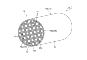
- the base material 10 is a honeycomb-shaped base material 10a.
- the honeycomb-shaped base material 10a includes partition walls 13 that define a plurality of cells 14.
- the cells 14 extend from the first end face E1 (inflow end face) to the second end face E2 (outflow end face) of the honeycomb base material 10a in the length direction (axial direction) of the honeycomb base material 10a (see FIG. 3). ).
- the cells 14 have any suitable shape in a cross section taken in a direction perpendicular to the length direction of the honeycomb-shaped base material 10a.
- Examples of the cross-sectional shape of the cell include a triangle, a quadrangle, a pentagon, a hexagon or more polygon, a circle, and an ellipse. All of the cross-sectional shapes and sizes of the cells may be the same, or at least some of them may be different. Among the cross-sectional shapes of such cells, preferred are hexagons and quadrangles, and more preferred are squares, rectangles, and hexagons.
- the cell density (that is, the number of cells 14 per unit area) in the cross section of the honeycomb-shaped base in the direction perpendicular to the length direction can be appropriately set depending on the purpose.
- the cell density can be, for example, from 4 cells/cm 2 to 320 cells/cm 2 . If the cell density is within this range, sufficient strength and effective GSA (geometric surface area) of the honeycomb-like base material can be ensured.
- the honeycomb-shaped base material 10a has any suitable shape (overall shape).
- Examples of the shape of the honeycomb-like base material include a columnar shape with a circular bottom surface, an elliptic columnar shape with an elliptical bottom surface, a prismatic shape with a polygonal bottom surface, and a columnar shape with an irregular bottom surface.
- the illustrated honeycomb base material 10a has a cylindrical shape.
- the outer diameter and length of the honeycomb-shaped base material can be appropriately set depending on the purpose.
- the honeycomb-shaped base material may have a hollow region at its center in a cross section taken in a direction perpendicular to the length direction.
- the honeycomb-shaped base material 10a typically includes an outer peripheral wall 11 and partition walls 13 located inside the outer peripheral wall 11.
- the outer peripheral wall 11 and the partition wall 13 are integrally formed.
- the outer peripheral wall 11 and the partition wall 13 may be separate bodies.
- the outer peripheral wall 11 has a cylindrical shape.
- the thickness of the outer peripheral wall 11 can be arbitrarily and appropriately set.
- the thickness of the outer peripheral wall 11 is, for example, 0.1 mm to 10 mm.
- the partition wall 13 defines a plurality of cells 14. More specifically, the partition 13 has a first partition 13 a and a second partition 13 b that are orthogonal to each other, and the first partition 13 a and the second partition 13 b define a plurality of cells 14 .
- the cross-sectional shape of the cell 14 is a quadrilateral except for the portion where the first partition wall 13a and the second partition wall 13b contact the outer peripheral wall 11. Note that the configuration of the partition wall is not limited to the partition wall 13 described above.
- the partition wall may include a first partition wall extending in the radial direction and a second partition wall extending in the circumferential direction, which may define a plurality of cells.
- the thickness of the partition walls 13 can be appropriately set depending on the use of the honeycomb-shaped base material.
- the thickness of the partition wall 13 is typically thinner than the thickness of the outer peripheral wall 11.
- the thickness of the partition wall 13 is, for example, 0.03 mm to 0.6 mm.
- the thickness of the partition wall is measured by, for example, cross-sectional observation using a SEM (scanning electron microscope). If the thickness of the partition walls is within this range, the mechanical strength of the honeycomb-like base material can be made sufficient, and the opening area (the total area of cells in the cross section) can be made sufficient. can.
- the porosity of the partition wall 13 can be appropriately set depending on the purpose.
- the porosity of the partition wall 13 is, for example, 15% or more, preferably 20% or more, and is, for example, 70% or less, preferably 45% or less. Note that the porosity can be measured, for example, by mercury porosimetry.
- the bulk density of the partition wall 13 can be appropriately set depending on the purpose. Their bulk density is, for example, 0.10 g/cm 3 or more, preferably 0.20 g/cm 3 or more, and, for example, 0.60 g/cm 3 or less, preferably 0.50 g/cm 3 or less. Note that the bulk density can be measured, for example, by mercury porosimetry.
- a typical material for forming the partition wall 13 is ceramics.
- ceramics include silicon carbide, silicon-silicon carbide composite materials, cordierite, mullite, alumina, silicon nitride, spinel, silicon carbide-cordierite composite materials, lithium aluminum silicate, and aluminum titanate.
- the materials constituting the partition wall can be used alone or in combination.
- preferred are cordierite, alumina, mullite, silicon carbide, silicon-silicon carbide composite materials, and silicon nitride, and more preferred are silicon carbide and silicon-carbide. Examples include silicon-based composite materials.
- Such a honeycomb-shaped base material 10a is typically produced by the following method. First, a binder and water or an organic solvent are added as necessary to the material powder containing the ceramic powder described above, the resulting mixture is kneaded to form a clay, and the clay is molded into a desired shape (typically (extrusion molding), followed by drying and, if necessary, firing, to produce the honeycomb-shaped base material 10a. When firing, it is fired at, for example, 1200°C to 1500°C. The firing time is, for example, 1 hour or more and 20 hours or less.
- the acidic gas adsorption layer 15 is formed on the surface of the partition wall 13.
- a gas flow path 16 is formed in a section of the cell 14 where the acid gas adsorption layer 15 is not formed (typically in the center).
- the acidic gas adsorption layer 15 may be formed on the entire inner surface of the partition wall 13 (that is, so as to surround the gas flow path 16) as in the illustrated example, or may be formed on a part of the surface of the partition wall.
- the removal efficiency of acidic gas typically CO 2
- the removal efficiency of acidic gas typically CO 2
- the gas flow path 16 extends from the first end surface E1 (inflow end surface) to the second end surface E2 (outflow end surface).
- the cross-sectional shape of the gas flow path 16 includes the same cross-sectional shape as the cell 14 described above, preferably a hexagon or a quadrilateral, and more preferably a square, a rectangle, or a hexagon. All of the cross-sectional shapes and sizes of the gas flow paths 16 may be the same, or at least some of them may be different.
- the above-described gas to be treated in the adsorption step flows through the cell 14 (more specifically, the gas flow path 16).
- the above-described desorption gas flows through the cell 14 (more specifically, the gas flow path 16) in the desorption process, and the above-described cooling gas flows in the cooling process.
- the acidic gas adsorption layer 15 contains an acidic gas adsorbent depending on the acidic gas to be adsorbed.
- the acidic gas adsorption layer 15 is a carbon dioxide adsorption layer 15a.
- the carbon dioxide adsorption layer 15a includes a carbon dioxide adsorption material as an example of an acidic gas adsorption material.
- carbon dioxide adsorbents include nitrogen-containing compounds described below; alkaline compounds such as sodium hydroxide and potassium hydroxide; carbonates such as calcium carbonate and potassium carbonate; hydrogen carbonates such as calcium hydrogen carbonate and potassium hydrogen carbonate; MOF.
- alkaline compounds such as sodium hydroxide and potassium hydroxide
- carbonates such as calcium carbonate and potassium carbonate
- hydrogen carbonates such as calcium hydrogen carbonate and potassium hydrogen carbonate
- MOF metal oxide
- organometallic frameworks such as MOF-74, MOF-200, and MOF-210
- zeolites zeolites
- activated carbon nitrogen-doped carbon
- ionic liquids ionic liquids.
- Carbon dioxide adsorbents can be used alone or in combination.
- nitrogen-containing compounds include primary amines such as monoethanolamine and polyvinylamine; secondary amines such as diethanolamine, cyclic amines, and N-(3-aminopropyl)diethanolamine; methyldiethylamine and triethanol.
- Tertiary amines such as amines; ethylene amine compounds such as tetraethylenepentamine; aminopropyltrimethoxysilane, 3-aminopropyltriethoxysilane, N-(2-aminoethyl)-3-aminopropyl-trimethoxysilane, Aminosilane coupling agents such as polyethyleneimine-trimethoxysilane; organic monomers having primary to tertiary amino groups such as ethyleneimine and styrene with amino groups; linear polyethyleneimine, primary Organic polymers having primary amino groups to tertiary amino groups such as branched polyethyleneimine having amino groups to tertiary amino groups; piperazine compounds such as 1-(2-hydroxyethyl)piperazine; polyamide amines, etc.
- Examples include amide compounds; polyvinylamine; and organic/inorganic compounds to which an amino group is added as a substituent.
- nitrogen-containing compounds methyldiethylamine, monoethanolamine, cyclic amine, diethanolamine, tetraethylenepentamine, ethyleneimine, linear polyethyleneimine, branched polyethyleneimine, and organic compounds with amino added as a substituent are preferred.
- /Inorganic compounds methyldiethylamine, monoethanolamine, cyclic amine, diethanolamine, tetraethylenepentamine, ethyleneimine, linear polyethyleneimine, branched polyethyleneimine, and organic compounds with amino added as a substituent are preferred. /Inorganic compounds.
- An ionic liquid is a liquid "salt” composed only of ions (anions and cations), and is in a liquid state at normal temperature and pressure (23° C., 0.1 MPaA (absolute pressure)).
- Examples of the cation of the ionic liquid include ammonium ions such as imidazolium salts and pyridinium salts, phosphonium ions, sulfonium salts, and inorganic ions.
- anion of the ionic liquid examples include halogen-based anions such as bromide ion and triflate; boron-based such as tetraphenylborate; phosphorus-based such as hexafluorophosphate; and sulfur-based such as alkyl sulfonate.
- halogen-based anions such as bromide ion and triflate
- boron-based such as tetraphenylborate
- phosphorus-based such as hexafluorophosphate
- sulfur-based such as alkyl sulfonate.
- a combination of imidazolium salts as a cation and triflate as an anion is preferably used.
- the ionic liquid is more preferably used in combination with a carbon dioxide adsorbent other than the ionic liquid (hereinafter referred to as "other carbon dioxide adsorbent").
- the ionic liquid coats other carbon dioxide adsorbents (eg, nitrogen-containing compounds). Therefore, it is possible to improve the performance and extend the life of the carbon dioxide adsorbent.
- the content ratio of the ionic liquid is, for example, 0.000001 parts by mass or more, preferably 0.00001 parts by mass or more, and, for example, 0.1 parts by mass or less, preferably 0. It is .05 parts by mass or less. When the content ratio of the ionic liquid is within the above range, it is possible to stably improve the performance and extend the life of the carbon dioxide adsorbent.
- the carbon dioxide adsorption layer 15a further includes a porous carrier in addition to the carbon dioxide adsorption material described above.
- the carbon dioxide adsorbent is typically supported on a porous carrier and faces the gas flow path.
- the carbon dioxide adsorption layer contains a porous carrier, it is possible to suppress the carbon dioxide adsorbent from falling off from the carbon dioxide adsorption layer during the adsorption step and/or the desorption step.
- the porous carrier can form mesopores in the carbon dioxide adsorption layer.
- porous carriers include organometallic frameworks (MOF) such as MOF-74, MOF-200, MOF-210; activated carbon; nitrogen-doped carbon; mesoporous silica; mesoporous alumina; zeolite; carbon nanotubes; polyvinylidene fluoride (PVDF); ), and preferred examples include metal organic frameworks (MOF), PVDF, activated carbon, zeolite, mesoporous silica, and mesoporous alumina.
- Porous carriers can be used alone or in combination.
- the porous carrier is preferably made of a material different from that of the carbon dioxide adsorbent.
- the BET specific surface area of the porous carrier is, for example, 50 m 2 /g or more, preferably 500 m 2 /g or more. If the surface area of the porous carrier is at least the above-mentioned lower limit, the carbon dioxide adsorbent can be supported stably, and the CO 2 recovery rate can be improved.
- the upper limit of the BET specific surface area of the porous carrier is typically 2000 m 2 /g or less.
- the total content of the carbon dioxide adsorption material and the porous carrier in the carbon dioxide adsorption layer is, for example, 30% by mass or more, preferably 50% by mass. or more, and is, for example, 100% by mass or less, preferably 99% by mass or less.
- the content of the carbon dioxide adsorbent in the carbon dioxide adsorption layer is, for example, 30% by mass or more, preferably 50% by mass or more, and, for example, 99% by mass or less.
- the content ratio of the porous carrier is, for example, 0.01 parts by mass or more, preferably 0.3 parts by mass or more, and, for example, 0.7 parts by mass or less, preferably 0. .5 parts by mass or less. When the content of the porous carrier is within the above range, the carbon dioxide adsorbent can be supported even more stably.
- the carbon dioxide adsorption layer may be composed only of the carbon dioxide adsorption material.
- the carbon dioxide adsorbent is directly supported on the partition wall 13 and faces the gas flow path.
- the content of the carbon dioxide adsorption material in the carbon dioxide adsorption layer is typically 95.0% by mass or more and 100% by mass or less.
- an excellent CO 2 recovery rate can be stably ensured.
- Such a carbon dioxide adsorption layer is typically produced by the following method.
- a solution of the carbon dioxide adsorbent is prepared by dissolving the carbon dioxide adsorbent described above in a solvent.
- the above-mentioned porous carrier is added to the solvent as necessary.
- the order of addition of the carbon dioxide adsorbent and the porous carrier is not particularly limited.
- a solution of the carbon dioxide adsorbent is applied onto the base material (specifically, the partition wall), and then the coating film is dried and optionally sintered to form a carbon dioxide adsorption layer.
- the acidic gas adsorption device 1 may include a heating body in addition to the base material 10 and the acidic gas adsorption layer 15.
- the heating body can heat the base material 10.
- the heating element is typically in contact with the substrate 10.
- each of the acid gas adsorption device 1 and the acid gas adsorption device 7 may further include a case.
- the case has a cylindrical shape (hollow shape) through which fluid can pass, and houses the acid gas adsorption section 19 .
- Examples of the cylindrical shape include a cylindrical shape and a rectangular cylindrical shape.
- the acidic gas adsorption unit 19 is typically supported by the case so as not to be relatively movable.
- the entire acid gas adsorption section 19 is cooled to the above-mentioned cooling temperature.
- the cooling gas passes through the entire acid gas adsorption section 19 that is supported in a relatively immovable manner by the case.
- the desorption section into which high-temperature gas flows and the cooling section into which cooling gas flows are adjacent to each other across a boundary plate, so the cooling section near the boundary plate
- the cooling efficiency is lower than that in the central region of the cooling section due to the heat from the high-temperature desorption section.
- the cooling section near the boundary plate is in contact with oxygen at a high temperature for a long time, and there may be a difference in the oxidative deterioration of the acid gas adsorbent in the central region of the cooling section and in the vicinity of the boundary plate.
- the entire acidic gas adsorption section can be cooled uniformly because the cooling section is not adjacent to the desorption section where high-temperature gas is desorbed during the cooling process. Therefore, oxidative deterioration can be uniformly suppressed in the entire gas adsorption section.
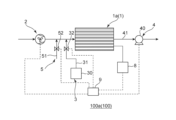
- the illustrated acidic gas recovery system 100 includes, in addition to the acidic gas adsorption device, an acidic gas supply blower 2, a desorption gas supply unit 5, a cooling gas supply unit 3, a recovery unit 4, and a thermometer 8. , and a control section 9.
- the illustrated acidic gas recovery system 100 includes an acidic gas adsorption device 1, an acidic gas supply blower 2, a desorption gas supply unit 5, a cooling gas supply unit 3, a recovery unit 4, a thermometer 8, and a control section. 9, but the number is not particularly limited as long as it is 1 or more.
- the acidic gas recovery system 100 is a carbon dioxide recovery system 100a that includes a carbon dioxide adsorption device 1a as an example of the acidic gas adsorption device 1.
- the acid gas recovery system 100 may include an acid gas adsorption device 7 (carbon dioxide adsorption device 7a) instead of the acid gas adsorption device 1 (carbon dioxide adsorption device 1a).
- Air blower for supplying acidic gas The blower 2 for supplying acidic gas supplies the above-mentioned gas to be treated (typically CO2- containing gas) to the acidic gas adsorption device 1 (typically the acidic gas adsorption unit 19) in the adsorption process. configured to supply.
- the illustrated blower 2 for supplying acidic gas is capable of blowing a target gas containing acidic gas toward the acidic gas adsorption device 1 .
- the acidic gas supply blower 2 may have any suitable configuration.
- connection between the acidic gas supply blower 2 and the acidic gas adsorption device 1 may be a pipe, or may be a part of the container that houses the acidic gas adsorption device 1 on the upstream side of the acidic gas adsorption device.
- the desorption gas supply unit 5 is configured to supply the desorption gas described above to the acidic gas adsorption device 1 (typically the acidic gas adsorption section 19) in the desorption process.
- the illustrated desorption gas supply unit 5 includes a desorption gas supply line 51 and a first on-off valve 52 .
- the desorption gas supply line 51 is typically a pipe that can supply the above-described desorption gas to the acidic gas adsorption device 1 .
- a downstream end of the desorption gas supply line 51 in the desorption gas supply direction is connected to a portion between the acidic gas supply blower 2 and the acidic gas adsorption device 1 .
- the upstream end of the desorption gas supply line 51 in the direction of supply of the desorption gas is connected to an intermediate tank that stores the recovery gas, although not shown.
- the first on-off valve 52 is provided in the desorption gas supply line 51 and can open and close the desorption gas supply line 51 .
- Examples of the first on-off valve 52 include a ball valve, a gate valve, and a butterfly valve, and preferably a butterfly valve.
- the cooling gas supply unit 3 is configured to supply the above-mentioned cooling gas to the acidic gas adsorption device 1 (typically the acidic gas adsorption unit 19) in the cooling process.
- the illustrated cooling gas supply unit 3 includes a cooling gas device 30, a cooling gas supply line 31, and a second on-off valve 32.
- the cooling gas device 30 is capable of generating and storing the above-mentioned cooling gas.
- the cooling gas supply line 31 is typically a pipe that can supply the above-mentioned cooling gas from the cooling gas device 30 to the acidic gas adsorption device 1.
- the second on-off valve 32 is provided in the cooling gas supply line 31 and can open and close the cooling gas supply line 31. Examples of the second on-off valve 32 include those similar to the first on-off valve 52 described above.
- the recovery unit 4 is configured to recover the acidic gas desorbed in the desorption step.
- the recovery unit 4 is capable of recovering the cooling gas that has passed through the acid gas adsorption device 1 (typically the acid gas adsorption section 19) in the cooling process.
- the illustrated recovery unit 4 includes a suction pump 40 and a gas discharge section 41.
- the suction pump 40 is capable of suctioning gas within the acidic gas adsorption device.
- An example of the suction pump 40 is a vacuum pump. Gas discharged from the acid gas adsorption device 1 and directed toward the suction pump 40 passes through the gas discharge section 41 .
- the gas discharge section 41 may be a pipe, or may be a portion of the container housing the acid gas adsorption device 1 on the downstream side of the acid gas adsorption device.
- thermometer 8 can measure the temperature of the acidic gas adsorption device 1 , typically the temperature of the acidic gas adsorption unit 19 , and preferably the temperature of the base material 10 .
- Thermometer 8 can adopt any suitable configuration.
- the control unit 9 can control the operation of the acid gas recovery system 100.
- the control unit 9 can adopt any suitable configuration.
- the control unit 9 includes, for example, a central processing unit (CPU), ROM, and RAM.
- the acid gas recovery method includes, in order, the above-described adsorption step, the substitution step, the above-described desorption step, and the above-described cooling step.
- the acidic gas adsorption apparatus 1 is provided with the honeycomb-shaped base material 10a, the acidic gas adsorption layer 15, and the heating body which is not illustrated is explained in detail.
- an adsorption step is first performed.
- the control unit 9 closes the first on-off valve 52 and the second on-off valve 32 and drives the acidic gas supply blower 2.
- the above-mentioned gas to be treated is sent out by the acidic gas supply blower 2, supplied to the acidic gas adsorption unit 19 of the acidic gas adsorption device 1, and distributed through the gas flow path 16.
- the temperature of the acidic gas adsorption device in the adsorption step (typically the temperature of the acidic gas adsorption unit 19) is adjusted in advance to the above-mentioned adsorption temperature.
- the temperature range of the gas to be treated that is supplied to the acidic gas adsorption device is the same as the above-described adsorption temperature range.
- the temperature of the gas to be treated may be the same as or different from the adsorption temperature of the acidic gas adsorption device.
- the pressure of the gas to be treated is, for example, 0.3 ⁇ 10 5 PaA (absolute pressure) or more and 2.0 ⁇ 10 5 PaA or less.
- the relative humidity RH of the gas to be treated is, for example, 10% RH or more and 60% RH or less.
- the flow velocity of the gas to be treated is, for example, 0.5 m/sec or more and 5 m/sec or less.
- control unit 9 stops driving the acidic gas supply blower 2, and the adsorption process is completed.
- the control unit 9 changes the first on-off valve 52 from the closed state to the open state and drives the suction pump 40.
- the desorption gas described above passes through the desorption gas supply line 51, is supplied to the acidic gas adsorption unit 19 of the acidic gas adsorption device 1, and flows through the gas flow path 16.
- the gas to be treated in the gas flow path 16 is replaced with the desorption gas.
- the temperature range of the desorption gas supplied to the acidic gas adsorption device is the same as the above-mentioned adsorption temperature range.
- the pressure of the desorption gas is, for example, 0.1 ⁇ 10 4 PaA or more and 1.0 ⁇ 10 4 PaA or less, and, for example, 0.1 ⁇ 10 4 PaA or more and 5.0 ⁇ 10 4 PaA or less.
- the implementation time of the replacement step (hereinafter referred to as replacement time) is, for example, 1 minute or more and 30 minutes or less.
- a purge gas different from the desorption gas may be introduced into the acidic gas adsorption device to replace the target gas in the acidic gas adsorption device with the purge gas.
- the pressure of the purge gas is, for example, 0.1 ⁇ 10 4 PaA or more and 11 ⁇ 10 4 PaA or less.
- the replacement time is, for example, 1 minute or more and 30 minutes or less.
- the purge gas include water vapor, carbon dioxide, nitrogen, and argon.
- the control unit 9 controls a heating body (not shown) to heat the acid gas adsorption device 1 (typically the acid gas adsorption unit 19) while maintaining the drive of the suction pump 40. Note that heating of the acid gas adsorption device may be started in the middle of the replacement step.
- the temperature of the acid gas adsorption device typically the temperature of the acid gas adsorption unit 19
- the acid gas held by the acid gas adsorption material is desorbed (released) from the acid gas adsorption material. be done.
- the desorbed acidic gas is discharged from the acidic gas adsorption device 1 together with the desorbed gas, passes through the gas discharge section 41 and the suction pump 40, and then is stored in an intermediate tank as required.
- recovered gas can be used for various purposes, and may be re-supplied to the acid gas adsorption device as desorption gas as mentioned above, and can be used as a raw material for various industrial products (e.g. carbonization). It can also be used as a raw material for hydrogen fuel.
- control unit 9 monitors the temperature of the acid gas adsorption device 1 using the thermometer 8, and controls the temperature of the acid gas adsorption device 1 (typically, the temperature of the acid gas adsorption unit 19) to be above the temperature range.
- the output of the heating element can be controlled so as not to exceed the desorption temperature range.
- the control unit 9 first controls the heating element to stop heating the acid gas adsorption device 1 . Thereafter, the control unit 9 changes the first on-off valve 52 from the open state to the closed state, and changes the second on-off valve 32 from the closed state to the open state, while maintaining the drive of the suction pump 40. Then, the above-mentioned cooling gas passes through the cooling gas supply line 31, is supplied to the acidic gas adsorption unit 19 of the acidic gas adsorption device 1, and flows through the gas flow path 16. As a result, the acidic gas adsorption device 1 (typically the acidic gas adsorption section 19) is cooled.
- the control unit 9 monitors the temperature of the acid gas adsorption device 1 using the thermometer 8, and cools the acid gas adsorption device 1 (typically the temperature of the acid gas adsorption unit 19) to a desired cooling temperature.
- the supply of cooling gas, which is an example of a cooling medium, to the acid gas adsorption device 1 is maintained until the acid gas adsorption device 1 is cooled.
- the cooling gas that has passed through the gas flow path 16 may be returned to the cooling gas device 30 after passing through the gas discharge section 41 and the suction pump 40 and being cooled as necessary.
- the acid gas recovery system 100 performs the adsorption process again following the cooling process. More specifically, after the control unit 9 stops driving the suction pump 40, the above-described adsorption step is performed again. In this way, in the acidic gas recovery system 100, the adsorption process, substitution process, desorption process, and cooling process can be repeated in order.
- the cooling gas in the cooling process, is supplied to the acidic gas adsorption device as the cooling medium, but the cooling medium may be a liquid refrigerant as described above.
- the liquid refrigerant contacts the base material 10 (honeycomb-shaped base material 10a) to cool the acid gas adsorption device 1.
- an acid gas recovery system 101 including an acid gas adsorption device that can be cooled with a liquid refrigerant will be described.
- the acid gas adsorption device (acid gas adsorption device 7 or acid gas adsorption device 1) is provided with a jacket 17, and the acid gas recovery system 101 is provided with a refrigerant supply unit 6 instead of the cooling gas supply unit 3.
- the acid gas recovery system 101 has the same configuration as the acid gas recovery system 100.
- the illustrated acid gas recovery system 101 includes an acid gas adsorption device 1 (carbon dioxide adsorption device 1a), but instead of the acid gas adsorption device 1 (carbon dioxide adsorption device 1a), an acid gas adsorption device 7 ( A carbon dioxide adsorption device 7a) may be provided.
- an acid gas adsorption device 1 carbon dioxide adsorption device 1a
- an acid gas adsorption device 7 A carbon dioxide adsorption device 7a
- the jacket 17 is provided on the outer surface of the acidic gas adsorption device.
- the illustrated jacket 17 is provided on the outer circumferential surface of the outer circumferential wall 11 (see FIG. 2) of the acidic gas adsorption device 1.
- the jacket 17 is configured to allow liquid refrigerant to flow therein. This allows the liquid refrigerant to come into contact with the outer peripheral wall 11 .
- the refrigerant supply unit 6 is configured to be able to circulate liquid refrigerant through the jacket 17.
- the refrigerant supply unit 6 includes a cooler 60, a refrigerant supply line 61, a refrigerant circulation line 62, and a pump 63.
- the cooler 60 is capable of cooling the circulating liquid refrigerant to below the outside temperature. Cooler 60 may employ any suitable configuration.
- the refrigerant supply line 61 is typically a pipe that can supply liquid refrigerant from the cooler 60 to the jacket 17 .
- the upstream end of the refrigerant supply line 61 in the liquid refrigerant supply direction is connected to the cooler 60 .
- a downstream end of the refrigerant supply line 61 in the liquid refrigerant supply direction is connected to the jacket 17 .
- the refrigerant return line 62 is typically a pipe that can return the liquid refrigerant that has passed through the jacket 17 to the cooler 60.
- the upstream end of the refrigerant return line 62 in the liquid refrigerant return direction is connected to the jacket 17 .
- a downstream end of the refrigerant return line 62 in the liquid refrigerant supply direction is connected to the cooler 60 .
- the pump 63 is provided in the refrigerant supply line 61 and can adjust the flow rate of the liquid refrigerant passing through the refrigerant supply line 61. Pump 63 may have any suitable configuration.
- the acid gas recovery method carried out by the acid gas recovery system 101 can be explained in the same manner as the acid gas recovery method carried out by the above-described acid gas recovery system 100, except for the cooling process. Therefore, explanations of the adsorption step, substitution step, and desorption step will be omitted.
- the control unit 9 drives the pump 63 after stopping the heating of the acid gas adsorption device by the heating body. Then, the liquid refrigerant cooled to a desired temperature in the cooler 60 is supplied to the jacket 17 via the refrigerant supply line 61.
- the liquid refrigerant contacts the outer peripheral wall 11 of the honeycomb-shaped base material 10a in the jacket 17 to cool the honeycomb-shaped base material 10a, and then is discharged from the jacket 17 and returned to the cooler 60 via the refrigerant return line 62. be done. Thereby, the liquid refrigerant circulates through the refrigerant supply unit 6 and the jacket 17 during the cooling process.
- the control unit 9 monitors the temperature of the acid gas adsorption device 1 using the thermometer 8, and maintains the circulation of the liquid refrigerant until the acid gas adsorption device 1 is cooled to a desired cooling temperature. This also allows the acid gas adsorption device to be cooled smoothly after the desorption step, and the cooling time can be shortened.
- the acid gas recovery system 100 when comparing the acid gas recovery system 101 shown in FIG. 5 with the acid gas recovery system 100 shown in FIG. 4, the acid gas recovery system 100 can be configured more easily than the acid gas recovery system 101. Therefore, acid gas recovery system 100 is preferable to acid gas recovery system 101.
- a cooling gas and a liquid refrigerant can also be used together as the cooling medium.
- the acid gas adsorption device is cooled by being supplied with cooling gas and liquid refrigerant.
- the acid gas adsorption device 1 is cooled by the cooling gas flowing through the cells and the liquid refrigerant coming into contact with the base material.
- the acid gas recovery system can include a cooling gas supply unit 3 and a refrigerant supply unit 6.
- the acid gas recovery method according to the embodiment of the present invention is used to separate and recover acid gas, and can be particularly suitably used in a carbon dioxide capture, utilization, and storage (CCUS) cycle.
- CCUS carbon dioxide capture, utilization, and storage
- Acid gas adsorption device 1a Carbon dioxide adsorption device 7 Acid gas adsorption device 7a Carbon dioxide adsorption device 10 Base material 10a Honeycomb-shaped base material 13 Partition wall 15 Acid gas adsorption layer 15a Carbon dioxide adsorption layer 100 Acid gas recovery system 100a Carbon dioxide recovery system
Landscapes
- Chemical & Material Sciences (AREA)
- Chemical Kinetics & Catalysis (AREA)
- Organic Chemistry (AREA)
- Analytical Chemistry (AREA)
- Inorganic Chemistry (AREA)
- Engineering & Computer Science (AREA)
- General Chemical & Material Sciences (AREA)
- Oil, Petroleum & Natural Gas (AREA)
- Treating Waste Gases (AREA)
Abstract
L'invention concerne un procédé de collecte de gaz acide avec lequel il est possible de réduire la dégradation par oxydation et l'abrasion provoquée par la volatilisation d'un matériau adsorbant les gaz acides. Le procédé de collecte de gaz acide selon un mode de réalisation de la présente invention comprend séquentiellement une étape d'absorption, une étape de désorption, et une étape de refroidissement. Dans l'étape d'absorption, un gaz à traiter contenant un gaz acide est fourni à un dispositif d'absorption de gaz acide comprenant un matériau adsorbant les gaz acides, et le gaz acide est absorbé par le matériau adsorbant les gaz acides. Dans l'étape de désorption, le dispositif d'absorption de gaz acide est chauffé, et le gaz acide est désorbé du matériau adsorbant les gaz acides. Dans l'étape de refroidissement, le dispositif d'absorption de gaz acide est refroidi par un milieu de refroidissement à une température inférieure à la température ambiante.
Applications Claiming Priority (2)
| Application Number | Priority Date | Filing Date | Title |
|---|---|---|---|
| JP2022-139537 | 2022-09-01 | ||
| JP2022139537 | 2022-09-01 |
Publications (1)
| Publication Number | Publication Date |
|---|---|
| WO2024048566A1 true WO2024048566A1 (fr) | 2024-03-07 |
Family
ID=90099508
Family Applications (1)
| Application Number | Title | Priority Date | Filing Date |
|---|---|---|---|
| PCT/JP2023/031179 WO2024048566A1 (fr) | 2022-09-01 | 2023-08-29 | Procédé de collecte de gaz acide |
Country Status (1)
| Country | Link |
|---|---|
| WO (1) | WO2024048566A1 (fr) |
Citations (7)
| Publication number | Priority date | Publication date | Assignee | Title |
|---|---|---|---|---|
| JPS51100972A (en) * | 1975-03-04 | 1976-09-06 | Toyo Boseki | Haigasukarano yozaikaishuho |
| JPS6183433U (fr) * | 1984-11-08 | 1986-06-02 | ||
| WO2019073866A1 (fr) * | 2017-10-10 | 2019-04-18 | 株式会社日立製作所 | Procédé de séparation/récupération de co2 et équipement de séparation/récupération de co2 |
| JP2019084489A (ja) * | 2017-11-06 | 2019-06-06 | 株式会社豊田中央研究所 | ガス分離装置 |
| JP2020531271A (ja) * | 2017-08-28 | 2020-11-05 | カサーレ ソシエテ アノニム | 温度スイング吸着方法 |
| JP2022067481A (ja) * | 2020-10-20 | 2022-05-06 | イビデン株式会社 | 構造体及び該構造体を備えた二酸化炭素回収装置 |
| US20220219109A1 (en) * | 2018-01-24 | 2022-07-14 | Exxonmobil Upstream Research Company | Apparatus and System for Swing Adsorption Processes |
-
2023
- 2023-08-29 WO PCT/JP2023/031179 patent/WO2024048566A1/fr unknown
Patent Citations (7)
| Publication number | Priority date | Publication date | Assignee | Title |
|---|---|---|---|---|
| JPS51100972A (en) * | 1975-03-04 | 1976-09-06 | Toyo Boseki | Haigasukarano yozaikaishuho |
| JPS6183433U (fr) * | 1984-11-08 | 1986-06-02 | ||
| JP2020531271A (ja) * | 2017-08-28 | 2020-11-05 | カサーレ ソシエテ アノニム | 温度スイング吸着方法 |
| WO2019073866A1 (fr) * | 2017-10-10 | 2019-04-18 | 株式会社日立製作所 | Procédé de séparation/récupération de co2 et équipement de séparation/récupération de co2 |
| JP2019084489A (ja) * | 2017-11-06 | 2019-06-06 | 株式会社豊田中央研究所 | ガス分離装置 |
| US20220219109A1 (en) * | 2018-01-24 | 2022-07-14 | Exxonmobil Upstream Research Company | Apparatus and System for Swing Adsorption Processes |
| JP2022067481A (ja) * | 2020-10-20 | 2022-05-06 | イビデン株式会社 | 構造体及び該構造体を備えた二酸化炭素回収装置 |
Similar Documents
| Publication | Publication Date | Title |
|---|---|---|
| US9457340B2 (en) | Methods of applying a sorbent coating on a substrate, a support, and/or a substrate coated with a support | |
| US9616375B2 (en) | Capture of carbon dioxide (CO2) from air | |
| US8858690B2 (en) | Thermally integrated adsorption-desorption systems and methods | |
| ES2901130T3 (es) | Método para producir un agente de adsorción para tratar gas comprimido y un dispositivo de adsorción provisto de dicho agente de adsorción | |
| EP2841179A1 (fr) | Matériau adsorbant durable et ensembles d'adsorbtion | |
| US20130255488A1 (en) | Method and apparatus for rapid adsorption-desorption co2 capture | |
| JP6999665B2 (ja) | 平行通路コンタクター及び吸着ガス分離方法 | |
| KR20190038061A (ko) | 흡착제 및 이를 포함하는 휘발성 유기화합물 제거시스템 | |
| JP2009090979A (ja) | 小型デシカント空調装置 | |
| WO2024048566A1 (fr) | Procédé de collecte de gaz acide | |
| WO2024048567A1 (fr) | Procédé de collecte de gaz acide | |
| WO2024048579A1 (fr) | Dispositif d'adsorption de gaz acide | |
| WO2024048568A1 (fr) | Système de récupération de gaz acide | |
| JP2009083851A (ja) | 小型デシカント空調装置 | |
| JP2014133219A (ja) | ガス除去装置およびそれを用いたガス除去方法 | |
| JP4352139B2 (ja) | 小型デシカント空調装置 | |
| WO2024048578A1 (fr) | Dispositif d'adsorption de gaz acide | |
| WO2024048577A1 (fr) | Dispositif d'adsorption de gaz acide | |
| WO2023248967A1 (fr) | Procédé de régénération pour dispositif d'adsorption de gaz acide, et procédé de fabrication de dispositif d'adsorption de gaz acide | |
| RU2583818C1 (ru) | Поглотитель и способ удаления диоксида углерода из газонаркозных смесей | |
| JPH037412B2 (fr) | ||
| US20230405511A1 (en) | Systems and Methods for Removing Carbon Dioxide from a Fluid | |
| US20240116028A1 (en) | Method of regenerating acid gas adsorption device and method of producing acid gas adsorption device | |
| WO2024004928A1 (fr) | Procédé de régénération pour dispositif d'adsorption de gaz acide, procédé de fabrication de dispositif d'adsorption de gaz acide, et procédé de fonctionnement pour dispositif d'adsorption de gaz acide | |
| JP2004141721A (ja) | 清浄空気生成装置及び清浄空気の生成方法 |
Legal Events
| Date | Code | Title | Description |
|---|---|---|---|
| 121 | Ep: the epo has been informed by wipo that ep was designated in this application |
Ref document number: 23860328 Country of ref document: EP Kind code of ref document: A1 |