WO2024048577A1 - Dispositif d'adsorption de gaz acide - Google Patents
Dispositif d'adsorption de gaz acide Download PDFInfo
- Publication number
- WO2024048577A1 WO2024048577A1 PCT/JP2023/031206 JP2023031206W WO2024048577A1 WO 2024048577 A1 WO2024048577 A1 WO 2024048577A1 JP 2023031206 W JP2023031206 W JP 2023031206W WO 2024048577 A1 WO2024048577 A1 WO 2024048577A1
- Authority
- WO
- WIPO (PCT)
- Prior art keywords
- acidic gas
- adsorption
- acidic
- adsorbent
- section
- Prior art date
Links
- 238000001179 sorption measurement Methods 0.000 title claims abstract description 329
- 230000002378 acidificating effect Effects 0.000 claims abstract description 293
- 239000003463 adsorbent Substances 0.000 claims abstract description 182
- 239000012530 fluid Substances 0.000 claims abstract description 81
- 239000000463 material Substances 0.000 claims description 44
- CURLTUGMZLYLDI-UHFFFAOYSA-N Carbon dioxide Chemical compound O=C=O CURLTUGMZLYLDI-UHFFFAOYSA-N 0.000 claims description 42
- 229910002092 carbon dioxide Inorganic materials 0.000 claims description 21
- 239000001569 carbon dioxide Substances 0.000 claims description 17
- 125000002924 primary amino group Chemical group [H]N([H])* 0.000 claims description 11
- 125000000467 secondary amino group Chemical group [H]N([*:1])[*:2] 0.000 claims description 11
- 125000001302 tertiary amino group Chemical group 0.000 claims description 11
- 239000007789 gas Substances 0.000 abstract description 367
- 239000002253 acid Substances 0.000 description 64
- 238000005192 partition Methods 0.000 description 32
- 238000003795 desorption Methods 0.000 description 26
- 238000010586 diagram Methods 0.000 description 9
- 238000011144 upstream manufacturing Methods 0.000 description 9
- 239000013305 flexible fiber Substances 0.000 description 7
- OKTJSMMVPCPJKN-UHFFFAOYSA-N Carbon Chemical compound [C] OKTJSMMVPCPJKN-UHFFFAOYSA-N 0.000 description 6
- QMMFVYPAHWMCMS-UHFFFAOYSA-N Dimethyl sulfide Chemical compound CSC QMMFVYPAHWMCMS-UHFFFAOYSA-N 0.000 description 6
- 229920002873 Polyethylenimine Polymers 0.000 description 6
- 238000000034 method Methods 0.000 description 6
- 229910010271 silicon carbide Inorganic materials 0.000 description 6
- VYPSYNLAJGMNEJ-UHFFFAOYSA-N Silicium dioxide Chemical compound O=[Si]=O VYPSYNLAJGMNEJ-UHFFFAOYSA-N 0.000 description 4
- PNEYBMLMFCGWSK-UHFFFAOYSA-N aluminium oxide Inorganic materials [O-2].[O-2].[O-2].[Al+3].[Al+3] PNEYBMLMFCGWSK-UHFFFAOYSA-N 0.000 description 4
- 239000002131 composite material Substances 0.000 description 4
- 239000000835 fiber Substances 0.000 description 4
- 150000002484 inorganic compounds Chemical class 0.000 description 4
- 229910010272 inorganic material Inorganic materials 0.000 description 4
- 150000002894 organic compounds Chemical class 0.000 description 4
- HBMJWWWQQXIZIP-UHFFFAOYSA-N silicon carbide Chemical compound [Si+]#[C-] HBMJWWWQQXIZIP-UHFFFAOYSA-N 0.000 description 4
- 125000001424 substituent group Chemical group 0.000 description 4
- 239000002033 PVDF binder Substances 0.000 description 3
- 239000000919 ceramic Substances 0.000 description 3
- 229910052878 cordierite Inorganic materials 0.000 description 3
- -1 cyclic amine Chemical class 0.000 description 3
- ZBCBWPMODOFKDW-UHFFFAOYSA-N diethanolamine Chemical compound OCCNCCO ZBCBWPMODOFKDW-UHFFFAOYSA-N 0.000 description 3
- 238000011049 filling Methods 0.000 description 3
- 238000010304 firing Methods 0.000 description 3
- 238000004519 manufacturing process Methods 0.000 description 3
- 239000012621 metal-organic framework Substances 0.000 description 3
- GNVRJGIVDSQCOP-UHFFFAOYSA-N n-ethyl-n-methylethanamine Chemical compound CCN(C)CC GNVRJGIVDSQCOP-UHFFFAOYSA-N 0.000 description 3
- QJGQUHMNIGDVPM-UHFFFAOYSA-N nitrogen group Chemical group [N] QJGQUHMNIGDVPM-UHFFFAOYSA-N 0.000 description 3
- 229920002981 polyvinylidene fluoride Polymers 0.000 description 3
- 238000000926 separation method Methods 0.000 description 3
- 125000006850 spacer group Chemical group 0.000 description 3
- HZAXFHJVJLSVMW-UHFFFAOYSA-N 2-Aminoethan-1-ol Chemical compound NCCO HZAXFHJVJLSVMW-UHFFFAOYSA-N 0.000 description 2
- IJGRMHOSHXDMSA-UHFFFAOYSA-N Atomic nitrogen Chemical compound N#N IJGRMHOSHXDMSA-UHFFFAOYSA-N 0.000 description 2
- NOWKCMXCCJGMRR-UHFFFAOYSA-N Aziridine Chemical compound C1CN1 NOWKCMXCCJGMRR-UHFFFAOYSA-N 0.000 description 2
- 229910052581 Si3N4 Inorganic materials 0.000 description 2
- XUIMIQQOPSSXEZ-UHFFFAOYSA-N Silicon Chemical compound [Si] XUIMIQQOPSSXEZ-UHFFFAOYSA-N 0.000 description 2
- RAHZWNYVWXNFOC-UHFFFAOYSA-N Sulphur dioxide Chemical compound O=S=O RAHZWNYVWXNFOC-UHFFFAOYSA-N 0.000 description 2
- 229910021536 Zeolite Inorganic materials 0.000 description 2
- 239000012298 atmosphere Substances 0.000 description 2
- 239000000969 carrier Substances 0.000 description 2
- 239000004927 clay Substances 0.000 description 2
- 230000007423 decrease Effects 0.000 description 2
- JSKIRARMQDRGJZ-UHFFFAOYSA-N dimagnesium dioxido-bis[(1-oxido-3-oxo-2,4,6,8,9-pentaoxa-1,3-disila-5,7-dialuminabicyclo[3.3.1]nonan-7-yl)oxy]silane Chemical compound [Mg++].[Mg++].[O-][Si]([O-])(O[Al]1O[Al]2O[Si](=O)O[Si]([O-])(O1)O2)O[Al]1O[Al]2O[Si](=O)O[Si]([O-])(O1)O2 JSKIRARMQDRGJZ-UHFFFAOYSA-N 0.000 description 2
- KZHJGOXRZJKJNY-UHFFFAOYSA-N dioxosilane;oxo(oxoalumanyloxy)alumane Chemical compound O=[Si]=O.O=[Si]=O.O=[Al]O[Al]=O.O=[Al]O[Al]=O.O=[Al]O[Al]=O KZHJGOXRZJKJNY-UHFFFAOYSA-N 0.000 description 2
- HNPSIPDUKPIQMN-UHFFFAOYSA-N dioxosilane;oxo(oxoalumanyloxy)alumane Chemical compound O=[Si]=O.O=[Al]O[Al]=O HNPSIPDUKPIQMN-UHFFFAOYSA-N 0.000 description 2
- QSHDDOUJBYECFT-UHFFFAOYSA-N mercury Chemical compound [Hg] QSHDDOUJBYECFT-UHFFFAOYSA-N 0.000 description 2
- 229910052753 mercury Inorganic materials 0.000 description 2
- 229910052863 mullite Inorganic materials 0.000 description 2
- 239000008188 pellet Substances 0.000 description 2
- 238000002459 porosimetry Methods 0.000 description 2
- 239000000843 powder Substances 0.000 description 2
- 238000011084 recovery Methods 0.000 description 2
- SBEQWOXEGHQIMW-UHFFFAOYSA-N silicon Chemical compound [Si].[Si] SBEQWOXEGHQIMW-UHFFFAOYSA-N 0.000 description 2
- 239000010703 silicon Substances 0.000 description 2
- 229910052710 silicon Inorganic materials 0.000 description 2
- 239000000377 silicon dioxide Substances 0.000 description 2
- HQVNEWCFYHHQES-UHFFFAOYSA-N silicon nitride Chemical compound N12[Si]34N5[Si]62N3[Si]51N64 HQVNEWCFYHHQES-UHFFFAOYSA-N 0.000 description 2
- 239000002904 solvent Substances 0.000 description 2
- FAGUFWYHJQFNRV-UHFFFAOYSA-N tetraethylenepentamine Chemical compound NCCNCCNCCNCCN FAGUFWYHJQFNRV-UHFFFAOYSA-N 0.000 description 2
- 239000010457 zeolite Substances 0.000 description 2
- WYTZZXDRDKSJID-UHFFFAOYSA-N (3-aminopropyl)triethoxysilane Chemical compound CCO[Si](OCC)(OCC)CCCN WYTZZXDRDKSJID-UHFFFAOYSA-N 0.000 description 1
- SJECZPVISLOESU-UHFFFAOYSA-N 3-trimethoxysilylpropan-1-amine Chemical compound CO[Si](OC)(OC)CCCN SJECZPVISLOESU-UHFFFAOYSA-N 0.000 description 1
- MGWGWNFMUOTEHG-UHFFFAOYSA-N 4-(3,5-dimethylphenyl)-1,3-thiazol-2-amine Chemical compound CC1=CC(C)=CC(C=2N=C(N)SC=2)=C1 MGWGWNFMUOTEHG-UHFFFAOYSA-N 0.000 description 1
- 229910000505 Al2TiO5 Inorganic materials 0.000 description 1
- 229920003043 Cellulose fiber Polymers 0.000 description 1
- RWSOTUBLDIXVET-UHFFFAOYSA-N Dihydrogen sulfide Chemical compound S RWSOTUBLDIXVET-UHFFFAOYSA-N 0.000 description 1
- VEXZGXHMUGYJMC-UHFFFAOYSA-N Hydrochloric acid Chemical compound Cl VEXZGXHMUGYJMC-UHFFFAOYSA-N 0.000 description 1
- 239000013118 MOF-74-type framework Substances 0.000 description 1
- 239000004698 Polyethylene Substances 0.000 description 1
- GSEJCLTVZPLZKY-UHFFFAOYSA-N Triethanolamine Chemical compound OCCN(CCO)CCO GSEJCLTVZPLZKY-UHFFFAOYSA-N 0.000 description 1
- 239000013233 Zn4O(BBC)2 Substances 0.000 description 1
- 239000013231 Zn4O(BTE)(BPDC) Substances 0.000 description 1
- JFBZPFYRPYOZCQ-UHFFFAOYSA-N [Li].[Al] Chemical compound [Li].[Al] JFBZPFYRPYOZCQ-UHFFFAOYSA-N 0.000 description 1
- 125000003277 amino group Chemical group 0.000 description 1
- 239000011230 binding agent Substances 0.000 description 1
- 229910052799 carbon Inorganic materials 0.000 description 1
- 239000002041 carbon nanotube Substances 0.000 description 1
- 229910021393 carbon nanotube Inorganic materials 0.000 description 1
- 229920002678 cellulose Polymers 0.000 description 1
- 239000001913 cellulose Substances 0.000 description 1
- 239000011248 coating agent Substances 0.000 description 1
- 238000000576 coating method Methods 0.000 description 1
- 239000007822 coupling agent Substances 0.000 description 1
- 230000003247 decreasing effect Effects 0.000 description 1
- 238000001035 drying Methods 0.000 description 1
- 230000007613 environmental effect Effects 0.000 description 1
- 238000011067 equilibration Methods 0.000 description 1
- UYMKPFRHYYNDTL-UHFFFAOYSA-N ethenamine Chemical class NC=C UYMKPFRHYYNDTL-UHFFFAOYSA-N 0.000 description 1
- 238000011156 evaluation Methods 0.000 description 1
- 238000001125 extrusion Methods 0.000 description 1
- 239000004744 fabric Substances 0.000 description 1
- IXCSERBJSXMMFS-UHFFFAOYSA-N hydrogen chloride Substances Cl.Cl IXCSERBJSXMMFS-UHFFFAOYSA-N 0.000 description 1
- 229910000041 hydrogen chloride Inorganic materials 0.000 description 1
- 229910000037 hydrogen sulfide Inorganic materials 0.000 description 1
- 230000001788 irregular Effects 0.000 description 1
- 239000000203 mixture Substances 0.000 description 1
- PHQOGHDTIVQXHL-UHFFFAOYSA-N n'-(3-trimethoxysilylpropyl)ethane-1,2-diamine Chemical compound CO[Si](OC)(OC)CCCNCCN PHQOGHDTIVQXHL-UHFFFAOYSA-N 0.000 description 1
- 229910052757 nitrogen Inorganic materials 0.000 description 1
- JCXJVPUVTGWSNB-UHFFFAOYSA-N nitrogen dioxide Inorganic materials O=[N]=O JCXJVPUVTGWSNB-UHFFFAOYSA-N 0.000 description 1
- 239000004745 nonwoven fabric Substances 0.000 description 1
- 239000003960 organic solvent Substances 0.000 description 1
- 125000002524 organometallic group Chemical group 0.000 description 1
- 150000004885 piperazines Chemical class 0.000 description 1
- 229920000962 poly(amidoamine) Polymers 0.000 description 1
- 229920000573 polyethylene Polymers 0.000 description 1
- 229920000139 polyethylene terephthalate Polymers 0.000 description 1
- 239000005020 polyethylene terephthalate Substances 0.000 description 1
- 150000003141 primary amines Chemical class 0.000 description 1
- 239000011164 primary particle Substances 0.000 description 1
- AABBHSMFGKYLKE-SNAWJCMRSA-N propan-2-yl (e)-but-2-enoate Chemical compound C\C=C\C(=O)OC(C)C AABBHSMFGKYLKE-SNAWJCMRSA-N 0.000 description 1
- 150000003335 secondary amines Chemical class 0.000 description 1
- FZHAPNGMFPVSLP-UHFFFAOYSA-N silanamine Chemical compound [SiH3]N FZHAPNGMFPVSLP-UHFFFAOYSA-N 0.000 description 1
- 229910052596 spinel Inorganic materials 0.000 description 1
- 239000011029 spinel Substances 0.000 description 1
- 150000003512 tertiary amines Chemical class 0.000 description 1
- 238000010792 warming Methods 0.000 description 1
- XLYOFNOQVPJJNP-UHFFFAOYSA-N water Substances O XLYOFNOQVPJJNP-UHFFFAOYSA-N 0.000 description 1
- 239000002759 woven fabric Substances 0.000 description 1
Images


Classifications
-
- B—PERFORMING OPERATIONS; TRANSPORTING
- B01—PHYSICAL OR CHEMICAL PROCESSES OR APPARATUS IN GENERAL
- B01D—SEPARATION
- B01D53/00—Separation of gases or vapours; Recovering vapours of volatile solvents from gases; Chemical or biological purification of waste gases, e.g. engine exhaust gases, smoke, fumes, flue gases, aerosols
- B01D53/14—Separation of gases or vapours; Recovering vapours of volatile solvents from gases; Chemical or biological purification of waste gases, e.g. engine exhaust gases, smoke, fumes, flue gases, aerosols by absorption
- B01D53/18—Absorbing units; Liquid distributors therefor
-
- Y—GENERAL TAGGING OF NEW TECHNOLOGICAL DEVELOPMENTS; GENERAL TAGGING OF CROSS-SECTIONAL TECHNOLOGIES SPANNING OVER SEVERAL SECTIONS OF THE IPC; TECHNICAL SUBJECTS COVERED BY FORMER USPC CROSS-REFERENCE ART COLLECTIONS [XRACs] AND DIGESTS
- Y02—TECHNOLOGIES OR APPLICATIONS FOR MITIGATION OR ADAPTATION AGAINST CLIMATE CHANGE
- Y02C—CAPTURE, STORAGE, SEQUESTRATION OR DISPOSAL OF GREENHOUSE GASES [GHG]
- Y02C20/00—Capture or disposal of greenhouse gases
- Y02C20/40—Capture or disposal of greenhouse gases of CO2
Definitions
- the present invention relates to an acid gas adsorption device.
- Such acidic gases mainly include carbon dioxide (hereinafter sometimes referred to as CO 2 ), which causes global warming.
- CO 2 carbon dioxide
- a carbon dioxide capture, utilization, and storage (CCUS) cycle is known as a typical example of such an approach.
- a carbon dioxide adsorption device used for such separation and recovery of carbon dioxide a gas separation unit including a carbon dioxide adsorption section having a pellet structure has been proposed (see, for example, Patent Document 1).
- a carbon dioxide adsorbent adsorbs CO 2 at a predetermined adsorption temperature and desorbs CO 2 at a desorption temperature exceeding the adsorption temperature.
- the main object of the present invention is to provide an acidic gas adsorption device that can improve the adsorption efficiency of acidic gas.
- the acidic gas adsorption device includes an acidic gas adsorption section through which a fluid can pass in a predetermined direction.
- the acidic gas adsorption section includes an acidic gas adsorbent capable of adsorbing acidic gas.
- the acidic gas adsorption section includes a first adsorption section; and a second adsorption section disposed downstream of the first adsorption section in the fluid passage direction.
- the first adsorption section includes a first acidic gas adsorbent having a relatively small adsorption force for adsorbing acidic gas and a large adsorption capacity for acidic gas.
- the second adsorption section includes a second acidic gas adsorbent having a relatively large adsorption power for adsorbing acidic gas and a relatively small adsorption capacity for acidic gas.
- the acidic gas may be carbon dioxide.
- the acidic gas concentration reached at equilibrium in the first acidic gas adsorbent exceeds 100 ppm
- the concentration reached at equilibrium in the second acidic gas adsorbent exceeds 100 ppm.
- the acid gas concentration may be 100 ppm or less.
- the first acidic gas adsorbent may contain a tertiary amino group
- the second acidic gas adsorbent may contain a primary amino group and /or may contain a secondary amino group.
- the first adsorption section may be divided into a plurality of parts in a direction perpendicular to the passage direction of the fluid.
- the second adsorption section may be divided into a plurality of parts in a direction perpendicular to the passage direction of the fluid.
- the acidic gas adsorption device according to any one of [1] to [6] above may further include one case. One case may house the first suction section and the second suction section all at once.
- an acidic gas adsorption device that can improve the adsorption efficiency of acidic gas.
- FIG. 1 is a schematic diagram of an acid gas adsorption apparatus according to one embodiment of the present invention.
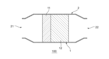
- FIG. 2 is a schematic configuration diagram of an acidic gas adsorption device according to another embodiment of the present invention.
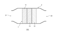
- FIG. 3 is a schematic configuration diagram of an acidic gas adsorption device according to yet another embodiment of the present invention.
- FIG. 4 is a schematic configuration diagram of an acidic gas adsorption device according to yet another embodiment of the present invention.
- FIG. 5 is a schematic configuration diagram of an acidic gas adsorption device according to yet another embodiment of the present invention.
- FIG. 6 is a schematic configuration diagram of an acidic gas adsorption device according to yet another embodiment of the present invention.
- FIG. 1 is a schematic diagram of an acid gas adsorption apparatus according to one embodiment of the present invention.
- FIG. 2 is a schematic configuration diagram of an acidic gas adsorption device according to another embodiment of the present invention.
- FIG. 3 is a schematic configuration diagram of an acidic gas
- FIG. 7 is a schematic configuration diagram of an acidic gas adsorption device according to yet another embodiment of the present invention.
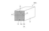
- FIG. 8 is a schematic configuration diagram of an embodiment of the first block in FIG. 6.
- 9 is a schematic perspective view of another embodiment of the first block of FIG. 6;
- FIG. 10 is a central sectional view of the first block of FIG. 9.
- FIG. 8 is a schematic configuration diagram of an embodiment of the first block in FIG. 6.
- 9 is a schematic perspective view of another embodiment of the first block of FIG. 6;
- FIG. 10 is a central sectional view of the first block of FIG. 9.
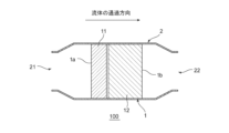
- FIG. 1 is a schematic configuration diagram of an acid gas adsorption apparatus according to one embodiment of the present invention.
- the illustrated acidic gas adsorption device 100 includes an acidic gas adsorption section 1 through which fluid can pass in a predetermined direction.
- the acidic gas adsorption unit 1 includes an acidic gas adsorbent capable of adsorbing acidic gas.
- the acidic gas adsorption section 1 includes a first adsorption section 11 and a second adsorption section 12 arranged downstream of the first adsorption section 11 in the fluid passage direction.
- the first adsorption unit 11 includes a first acidic gas adsorbent having a relatively small adsorption force for adsorbing acidic gas and a large adsorption capacity for acidic gas.
- the second adsorption section 12 includes a second acidic gas adsorbent having a relatively large adsorption power for adsorbing acidic gas and a small adsorption capacity for acidic gas.
- the acid gas adsorption capacity of the first acid gas adsorption material is smaller than the acid gas adsorption capacity of the second acid gas adsorption material
- the acid gas adsorption capacity of the first acid gas adsorption material is smaller than the acid gas adsorption capacity of the second acid gas adsorption material.
- an acidic gas adsorption device a fluid containing an acidic gas is supplied to an acidic gas adsorption section, and an acidic gas adsorbent adsorbs the acidic gas. Therefore, the acid gas concentration in the fluid decreases toward the downstream side in the fluid passage direction.
- the acidic gas adsorption section contains the same acidic gas adsorbent throughout, the concentration of acidic gas is relatively high in the upstream part of the acidic gas adsorption section, so the acidic gas adsorption material adsorbs the acidic gas.
- the acid gas adsorbent since the concentration of acid gas is relatively low in the downstream part of the acid gas adsorption section, the acid gas adsorbent may not be able to sufficiently adsorb acid gas.
- the first adsorption part located on the upstream side in the fluid passage direction has a first acidic gas adsorbent having a larger adsorption capacity for acidic gas than the second acidic gas adsorbent. Since it contains a gas adsorbent, the first acidic gas adsorbent can sufficiently adsorb acidic gas from a fluid having a relatively high concentration of acidic gas.
- the second adsorption section located on the downstream side in the fluid passage direction includes a second acidic gas adsorbent having a larger adsorption power for adsorbing acidic gas than the first acidic gas adsorption material, the second adsorption part Even if the concentration of acidic gas in the fluid that has passed through the second acidic gas adsorbent is relatively low, the second acidic gas adsorbent can stably adsorb acidic gas from the fluid. Therefore, compared to the case where the acidic gas adsorption section contains the same acidic gas adsorbent throughout, it is possible to improve the adsorption performance of the entire acidic gas adsorption device.
- acidic gases to be adsorbed by the acidic gas adsorption device examples include carbon dioxide (CO 2 ), hydrogen sulfide, sulfur dioxide, nitrogen dioxide, dimethyl sulfide (DMS), and hydrogen chloride.
- the acid gas is carbon dioxide ( CO2 ) and the fluid is a CO2 - containing gas.
- the CO 2 -containing gas may contain nitrogen in addition to CO 2 .
- the CO2 - containing gas is typically air (atmosphere).
- the CO 2 concentration in the CO 2 -containing gas before being supplied to the acidic gas adsorption device is, for example, 100 ppm (volume basis) or more and 2 volume % or less. Below, the case where the acidic gas is carbon dioxide (CO 2 ) will be explained in detail.
- the CO 2 adsorption capacity (hereinafter referred to as CO 2 adsorption capacity) of the first acidic gas adsorbent is larger than the CO 2 adsorption capacity of the second acidic gas adsorption material.
- the adsorption power of the first acidic gas adsorbent to adsorb CO 2 (hereinafter referred to as CO 2 adsorption power) is smaller than the CO 2 adsorption power of the second acidic gas adsorption material.
- the CO2 adsorption capacity of the acidic gas adsorbent is 1kg of the acidic gas adsorbent (when the acidic gas adsorbent is supported on a porous carrier, the This is the amount of CO 2 that can be adsorbed per 1 kg (total of gas adsorbent and porous carrier) (the same applies hereinafter).
- the CO 2 adsorption capacity of the first acidic gas adsorbent is, for example, 1.5 mol/kg-adsorbent or more, preferably 2.0 mol/kg-adsorbent or more, more preferably 2.5 mol/kg-adsorbent or more. .
- the CO 2 adsorption capacity can be measured, for example, by the method described in Document 3-2-1 of the 2nd Fiscal Year 2015 Carbon Dioxide Capture and Storage Field Evaluation Study Group (2) (the same applies hereinafter).
- the CO 2 adsorption power of the first acidic gas adsorbent can be evaluated based on the acidic gas concentration at equilibrium (CO 2 concentration at equilibrium).
- the CO 2 adsorption power of the acidic gas adsorbent is weaker as the equilibrium acid gas concentration (equilibrium reached CO 2 concentration) is higher, and stronger as the equilibrium reached acid gas concentration (equilibrium reached CO 2 concentration) is lower.
- the equilibrium acidic gas concentration (equilibrated CO 2 concentration) of the first acidic gas adsorbent exceeds, for example, 100 ppm, preferably exceeds 200 ppm, more preferably exceeds 300 ppm, and is, for example, 500 ppm or less.
- the acid gas concentration that reaches equilibrium can be determined, for example, by filling a desiccator with air at 25°C and 50% RH, and filling it with an acidic gas adsorbent having a large excess adsorption capacity than the acidic gas contained in the desiccator, and after 4 hours have elapsed.
- the acid gas concentration in the desiccator after this can be measured by quantitatively analyzing it using an infrared spectrometer (the same applies hereinafter).
- the first acidic gas adsorbent can adsorb a relatively large amount of CO 2 (more than the lower limit of the above CO 2 adsorption capacity).
- the CO 2 adsorption power of the acidic gas adsorbent increases, the energy required to desorb CO 2 from the acidic gas adsorbent increases. Therefore, when the CO 2 adsorption power of the first acidic gas adsorbent is below the above upper limit, energy saving can be achieved in the desorption step described below.
- the equilibrium acidic gas concentration (equilibrated CO 2 concentration) of the second acidic gas adsorbent is, for example, 100 ppm or less, preferably 75 ppm or less, more preferably 50 ppm or less, and, for example, 10 ppm or more.
- the CO 2 adsorption capacity of the second acidic gas adsorbent is, for example, less than 2.0 mol/kg-adsorbent, preferably less than 1.5 mol/kg-adsorbent, more preferably 1.0 mol/kg-adsorbent or less. , for example, 0.5 mol/kg of adsorbent or more.
- the CO 2 adsorption capacity of the second acidic gas adsorbent is equal to or higher than the above lower limit, then if the CO 2 concentration is relatively low (the CO 2 concentration is the lower limit of the equilibrium acidic gas concentration of the first acidic gas adsorbent (typically (100 ppm) or less), the second acidic gas adsorbent can stably adsorb CO 2 . Furthermore, even if the CO 2 adsorption capacity of the second acidic gas adsorbent is below the above upper limit, the first acidic gas adsorbent adsorbs a relatively large amount of CO 2 on the upstream side, so the acidic gas adsorption capacity is The acid gas adsorption efficiency of the device as a whole does not decrease.
- the first acidic gas adsorbent capable of adsorbing CO 2 typically contains at least a tertiary amino group.
- the primary acidic gas adsorbent may contain only a tertiary amino group as an amino group, or may contain a primary amino group and/or a secondary amino group in addition to a tertiary amino group. You can stay there.
- Examples of the first acidic gas adsorbent having a tertiary amino group include nitrogen-containing compounds having a tertiary amino group, specifically, tertiary amines such as methyldiethylamine and triethanolamine; Substituted piperazine compounds such as -(2-hydroxyethyl)piperazine; Branched polyethyleneimine having a primary amino group to a tertiary amino group; Organic/inorganic compounds to which a tertiary amino group is added as a substituent. It will be done.
- Such first acidic gas adsorbents can be used alone or in combination.
- preferable examples include methyldiethylamine, branched polyethyleneimine, and organic/inorganic compounds to which a tertiary amino group is added as a substituent.
- the second acidic gas adsorbent capable of adsorbing CO 2 typically contains a primary amino group and/or a secondary amino group.
- the second acidic gas adsorbent contains a primary amino group and/or a secondary amino group, and does not contain a tertiary amino group.
- Examples of the second acidic gas adsorbent include nitrogen-containing compounds having a primary amino group and/or a secondary amino group.
- nitrogen-containing compounds having a primary amino group and/or secondary amino group include primary amines such as monoethanolamine and polyvinylamine; diethanolamine, cyclic amines, N-(3-aminopropyl ) Secondary amines such as diethanolamine; ethyleneamine compounds such as tetraethylenepentamine; aminopropyltrimethoxysilane, 3-aminopropyltriethoxysilane, N-(2-aminoethyl)-3-aminopropyl-trimethoxysilane , aminosilane coupling agents such as polyethyleneimine-trimethoxysilane; ethyleneimine; linear polyethyleneimine; polyamidoamine having a primary amino group and/or a secondary amino group; Examples include polyvinylamine having a secondary amino group; organic/inorganic compounds to which a primary amino group and/or a secondary amino group is added as a substituent.
- Such second acidic gas adsorbents can be used alone or in combination.
- monoethanolamine, cyclic amine, diethanolamine, tetraethylenepentamine, ethyleneimine, linear polyethyleneimine, primary amino group and/or secondary amino group are preferably used.
- examples include organic/inorganic compounds provided as substituents.
- the first acid gas adsorbent is methyldiethylamine and the second acid gas adsorbent is polyethyleneimine.
- the first acidic gas adsorbent and the second acidic gas adsorbent are in the above-described specific combination, the CO 2 adsorption capacity and CO 2 adsorption power in these acidic gas adsorption parts can be ensured in a well-balanced manner, and the entire acidic gas adsorption device It is possible to further improve the adsorption performance of.
- the acidic gas adsorption device 100 includes an acidic gas adsorption section 1 including a first adsorption section 11 and a second adsorption section 12; and one case 2.
- the case 2 houses the acidic gas adsorption section 1.
- one case 2 houses the first suction section 11 and the second suction section 12 together. If one case houses the first adsorption part and the second adsorption part all at once, acidic Since the gas adsorption device can be downsized, equipment costs can be kept low, and the amount of acid gas recovered per unit area can be increased.
- the case 2 has a cylindrical shape extending in the fluid passage direction.
- the upstream end of the case 2 in the fluid passage direction is configured as a first opening 21 .
- the downstream end of the case 2 in the fluid passage direction is configured as a second opening 22 .
- the acidic gas adsorption unit 1 is arranged between the first opening 21 and the second opening 22 in the internal space of the case 2 .
- the first suction section 11 is arranged between the first opening 21 and the second suction section 12.
- the second suction section 12 is arranged on the opposite side of the first opening 21 with respect to the first suction section 11 .
- a fluid can pass through each of the first opening 21 and the second opening 22.
- the fluid containing acidic gas is supplied to the first adsorption section 11 through the first opening 21 .
- the fluid that has sequentially passed through the first suction section 11 and the second suction section 12 is discharged from the second opening 22.
- the first adsorption section 11 includes an upstream end surface 1a of the acid gas adsorption section 1 in the fluid passage direction.
- the second adsorption section 12 includes a downstream end surface 1b of the acid gas adsorption section 1 in the fluid passage direction.
- the passage direction of the fluid is typically perpendicular to each of the upstream end surface 1a and the downstream end surface 1b of the acidic gas adsorption section 1.
- the dimensions of the acid gas adsorption section 1 in the fluid passage direction are not particularly limited as long as the fan drive power does not increase due to pressure loss, and are, for example, 0.5 m or more, preferably 0.6 m or more, and, for example, 2.0 m or less. , preferably 1.0 m or less.
- the dimension of the acid gas adsorption unit 1 in the direction orthogonal to the fluid passage direction is not particularly limited, and is, for example, 1.5 m or more, preferably 2.0 m or more, and, for example, 4.0 m or less, preferably 3.0 m or less. It is.
- the dimensional ratio of each of the first adsorption part 11 and the second adsorption part 12 is, for example, 10% to 90%, preferably 20% to 80%. %, more preferably 30% to 70%. If the size ratio of each of the first adsorption part and the second adsorption part to the case is within such a range, a large acidic gas adsorption capacity can be ensured while maintaining excellent adsorption power in the entire acidic gas adsorption device.
- the distance between the first opening 21 and the upstream end surface 1a of the first adsorption section 11 in the fluid passage direction is, for example, 1 cm or more, preferably 5 cm or more, and more preferably 10 cm or more.
- the distance between the downstream end surface 1b of the second suction section 12 and the second opening 22 in the fluid passage direction is, for example, 1 cm or more, preferably 5 cm or more, and more preferably 10 cm or more.
- the acid gas adsorption section 1 may be constructed by integrating a first adsorption section 11 and a second adsorption section 12, and as shown in FIG. It may be divided into the suction section 11 and the second suction section 12.
- the acid gas adsorption section 1 is divided into a first adsorption section 11 and a second adsorption section 12 in the fluid passage direction, and the first adsorption section 11 and the second adsorption section 12 are separate bodies. (See Figure 1). If the first adsorption part and the second adsorption part are separated, each of the first adsorption part and the second adsorption part is Can be easily manufactured separately.
- a gap may be formed between the first suction part 11 and the second suction part 12 in the fluid passage direction.
- fluid flows easily near the center and is difficult to flow near the outer portions.
- variations in the fluid flow rate in the acidic gas adsorption section can be reduced.
- the dimensions of the gap are as follows: For example, it is 30% or less, preferably 10% or less.
- the size of the gap is below the above upper limit, it is possible to suppress the fluid from staying between the first adsorption part and the second adsorption part, and to allow the fluid to flow smoothly from the first adsorption part to the second adsorption part. Can be done.
- each of the first adsorption section 11 and the second adsorption section 12 in the fluid passage direction may take any appropriate value depending on the acidic gas adsorbent used.
- the dimension of the first suction section 11 in the fluid passage direction is longer than the dimension of the second suction section 12.
- the dimensions of the first adsorption section 11 are preferably 50% or more, for example, of the total length of the acid gas adsorption section 1 (the sum of the dimensions of the first adsorption section and the dimensions of the second adsorption section). is 60% or more, for example 90% or less, preferably 80% or less.
- the dimensions of the second adsorption section 12 are, for example, 10% or more, preferably 30% or more, and, for example, 50% or less, preferably 40%, of the total length of the acidic gas adsorption section 1. It is as follows. When the dimensions of the first adsorption section and/or the second adsorption section are within the above range, it is possible to stably improve the adsorption efficiency of acidic gas.
- the acidic gas adsorption unit 1 further includes a third adsorption unit 13 disposed between the first adsorption unit 11 and the second adsorption unit 12.
- a third adsorption unit 13 disposed between the first adsorption unit 11 and the second adsorption unit 12.
- the size range of the gap between the first suction part 11 or the second suction part 12 and the third suction part 13 is the range of the size of the gap between the first suction part 11 and the second suction part 12 described above. Same as range.
- the third adsorption section 13 may contain the same acidic gas adsorbent as the first adsorption section 11, as shown in FIG. It may be mixed with the acidic gas adsorbent of the second adsorption section 12.
- the third adsorption section 13 includes an acidic gas adsorbent different from the acidic gas adsorbent of the first adsorption section 11 and the acidic gas adsorption material of the second adsorption section 12 (see FIG. 4).
- the third adsorption section 13 preferably contains a third acidic gas adsorbent.
- the adsorption power of the third acidic gas adsorbent is larger than that of the first acidic gas adsorbent and smaller than that of the second acidic gas adsorbent.
- the adsorption capacity of the third acidic gas adsorbent is smaller than that of the first acidic gas adsorbent and larger than that of the second acidic gas adsorbent.
- the first acidic gas adsorbent, the third acidic gas adsorbent, and the second acidic gas adsorbent are arranged so that the adsorption power for acidic gas increases in this order. Therefore, it is possible to ensure a better balance between the CO 2 adsorption capacity and the CO 2 adsorption power in the acid gas adsorption unit, and it is possible to further improve the acid gas adsorption efficiency of the acid gas adsorption device.
- the CO 2 adsorption capacity of the third acidic gas adsorbent is, for example, 1.2 mol/kg or more, preferably 1.7 mol/kg or more, and more preferably 2.2 mol/kg or more.
- the equilibrium acid gas concentration (equilibration CO 2 concentration) of the third acidic gas adsorbent is, for example, 150 ppm or less, preferably 125 ppm or less, more preferably 100 ppm or less, and, for example, 75 ppm or more.
- a specific example of the third acidic gas adsorbent is polyethyleneimine.
- the first adsorption section 11 may be divided into a plurality of first blocks 11a in a direction perpendicular to the fluid passage direction.
- the first adsorption section 11 is constituted by a plurality of first blocks 11a arranged in a direction perpendicular to the fluid passage direction.
- the first suction section can be configured by manufacturing a relatively small first block. Therefore, the first suction section can be manufactured more easily than when the first suction section is manufactured all at once.
- the dimensions of the first block 11a in the fluid passage direction are, for example, 0.10 m or more, preferably 0.15 m or more, and, for example, 0.30 m or less, preferably 0.20 m or less.
- the dimension of the first block 11a in the direction orthogonal to the fluid passage direction is, for example, 0.10 m or more, preferably 0.15 m or more, and, for example, 0.80 m or less, preferably 0.60 m or less.
- the first blocks 11a that are adjacent to each other among the plurality of first blocks 11a may form a gap therebetween, or may be in contact with each other in a direction perpendicular to the fluid passage direction.
- the first suction section 11 is divided into four parts in a direction perpendicular to the fluid passage direction (vertical direction in the drawing).
- the number of divisions of the first adsorption section in the direction orthogonal to the fluid passage direction is not limited to this.
- the first suction section 11 can be divided into a plurality of parts also in a direction (depth direction in the drawing) perpendicular to the fluid passage direction.
- the number of divisions of the first adsorption section in the direction perpendicular to the fluid passage direction is, for example, 2 or more and 300 or less. Further, all of the plurality of first blocks 11a may contain the same first acidic gas adsorbent, or some of the plurality of first blocks 11a may contain different first acidic gas adsorbents. Good too.
- the second adsorption section 12 is divided into a plurality of second blocks 12a in a direction perpendicular to the fluid passage direction.
- the second adsorption section 12 is composed of a plurality of second blocks 12a arranged in a direction perpendicular to the fluid passage direction.
- the second suction section can be constructed by manufacturing a relatively small second block, and the second suction section can be easily manufactured.
- the range of dimensions of the second block 12a is similar to the range of dimensions of the first block 11a described above.
- the second blocks 12a that are adjacent to each other among the plurality of second blocks 12a may have a gap formed therebetween, or may be in contact with each other in a direction perpendicular to the fluid passage direction.
- the second suction section 12 is divided into four parts in a direction perpendicular to the fluid passage direction (vertical direction in the drawing).
- the number of divisions of the second adsorption section in the direction orthogonal to the fluid passage direction is not limited to this.
- the second adsorption section 12 can be divided into a plurality of parts also in a direction (depth direction in the drawing) perpendicular to the fluid passage direction.
- the number of divisions of the second suction section in the direction orthogonal to the fluid passage direction is, for example, 2 or more and 300 or less, and preferably the same as the number of divisions of the first suction section. Further, all of the plurality of second blocks 12a may contain the same second acidic gas adsorbent, or some of the plurality of second blocks 12a may contain different second acidic gas adsorbents. Good too.
- the third adsorption section 13 is divided into a plurality of third blocks 13a in a direction perpendicular to the fluid passage direction.
- the third adsorption section 13 is constituted by a plurality of third blocks 13a arranged in a direction perpendicular to the fluid passage direction.
- the third suction section can be constructed by manufacturing a relatively small third block, and the third suction section can be easily manufactured.
- the range of dimensions of the third block 13a is similar to the range of dimensions of the first block 11a described above.
- the third blocks 13a that are adjacent to each other among the plurality of third blocks 13a may form a gap therebetween, or may be in contact with each other in a direction perpendicular to the fluid passage direction.
- the third suction section 13 is divided into four parts in a direction perpendicular to the fluid passage direction (vertical direction in the drawing).
- the number of divisions of the third suction section in the direction orthogonal to the fluid passage direction is not limited to this.
- the third suction section 13 can be divided into a plurality of parts also in a direction perpendicular to the fluid passage direction (depth direction in the drawing).
- the number of divisions of the third suction section in the direction orthogonal to the fluid passage direction is, for example, 2 or more and 300 or less, and preferably the same as the number of divisions of the first suction section.
- all of the plurality of third blocks 13a may contain the same acidic gas adsorbent, or some of the plurality of third blocks 13a may contain different acidic gas adsorbents.
- the third block 13a located in the center part and the third block 13a located in the outer part contain different acidic gas adsorbents. More specifically, in the third adsorption section 13, the third block 13a located in the central part contains the above-mentioned third acidic gas adsorbent, and the third block 13a located in the outer part contains the above-mentioned second acid gas adsorbent. Contains acid gas adsorbent.
- the acidic gas adsorption section 1 can include a third adsorption section to an n-th adsorption section between the first adsorption section 11 and the second adsorption section 12.
- the nth adsorption section contains the nth acidic gas adsorbent.
- Each of these n-th adsorption parts may be divided into a plurality of n-th blocks in the direction orthogonal to the fluid passage direction, similarly to the above.
- n is, for example, 4 or more and 30 or less.
- the acidic gas adsorption unit includes the third adsorption unit to the nth adsorption unit, it is preferable that the adsorption force of the acidic gas adsorbent included in the adsorption unit located on the downstream side in the fluid passage direction is large.
- the acid gas adsorption unit 1 housed in one case 2 includes a first adsorption unit 11 and a second adsorption unit 12.
- the arrangement of the part and the second suction part is not limited to this.
- two cases 2 are connected in series in the fluid passage direction, and the upstream case 2 houses the first suction section 11, and the downstream case 2 houses the second suction section 12. may have been done. This also makes it possible to improve the adsorption performance of the acidic gas adsorption device, similarly to the above embodiment.
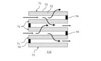
- the acid gas adsorption unit 1 includes at least the first adsorption unit 11 and the second adsorption unit 12. Further, the acidic gas adsorption section 1 may include a third adsorption section 13 to an n-th adsorption section. Each of the first to nth adsorption units typically has the same configuration except for the type of acidic gas adsorbent. Further, the first suction portion 11 (integrally formed) shown in FIG. 1 and the first block 11a shown in FIG. 5 have the same configuration except that they are different in size. Therefore, below, the first block 11a shown in FIG. 5 will be cited and its configuration will be explained in detail.
- the first block 11a includes a plurality of adsorbent layers 71.
- the plurality of adsorbent layers 71 are stacked at intervals in their thickness direction. In the illustrated example, five adsorbent layers 71 are arranged in parallel, but the number of adsorbent layers 71 is not limited to this.
- the number of adsorbent layers 71 is, for example, 5 or more, preferably 10 or more, and more preferably 20 or more.
- the interval between adjacent adsorbent layers 71 among the plurality of adsorbent layers 71 is, for example, 0.5 cm or more and 1.5 cm or less.
- Each of the plurality of adsorbent layers 71 includes a flexible fiber member 73 and a plurality of pellet-like adsorbents 72.
- the flexible fiber member 73 allows the passage of gas and restricts the passage of the pellet-like adsorbent.
- the flexible fiber member 73 is typically formed into a hollow shape (bag shape) capable of accommodating a plurality of pellet-like adsorbents 72.
- the flexible fiber member 73 may be a woven fabric or a nonwoven fabric.
- Examples of the material for the flexible fiber member 73 include organic fibers and natural fibers, preferably polyethylene terephthalate fibers, polyethylene fibers, and cellulose fibers.
- the thickness of the flexible fiber member 73 is, for example, 25 ⁇ m or more and 500 ⁇ m or less.
- a plurality of pellet-like adsorbents 72 are filled inside a flexible fiber member 73 having a hollow shape (bag shape).
- the pellet-like adsorbent 72 functions as an acidic gas adsorbent, and typically functions as a carbon dioxide adsorbent.
- Examples of the material of the pellet-like adsorbent 72 include materials modified with the above-described acidic gas adsorbent (first acidic gas adsorbent or second acidic gas adsorbent), and preferably the above-described acidic gas adsorbent.
- first acidic gas adsorbent or second acidic gas adsorbent more preferably the above-mentioned acidic gas adsorbent (first acidic gas adsorbent or second acidic gas adsorbent).
- examples include modified nanofibrous cellulose.
- the average primary particle diameter of the pellet-like adsorbent 72 is, for example, 60 ⁇ m or more and 1200 ⁇ m or less.
- the filling ratio of the pellet-like adsorbent 72 in the adsorbent layer 71 may be any appropriate value.
- the illustrated acidic gas adsorption device 1 further includes a plurality of spacers 74.
- the spacer 74 is sandwiched between adjacent adsorbent layers 71 among the plurality of adsorbent layers 71 . This makes it possible to stably ensure the spacing between adjacent adsorbent layers.
- the plurality of adsorbent layers 71 and the plurality of spacers 74 have an approximately 99-fold shape when viewed from a direction perpendicular to the thickness direction of the adsorbent layer 71 (the depth direction of the paper plane in FIG. 1). It is arranged so that
- the first block 11a typically includes a base material 3 and an acidic gas adsorption layer 4.
- the structure of the base material 3 is not particularly limited, and includes, for example, a honeycomb shape, a filter structure such as a filter cloth, a pellet structure, and the like.
- the acidic gas adsorption layer 4 is not particularly limited as long as it is placed on the surface of the base material 3.
- the base material 3 is a honeycomb-shaped base material 3a.
- the honeycomb-shaped base material 3a includes partition walls 32 that define a plurality of cells 33.
- the cells 33 extend from the first end face E1 (inflow end face) to the second end face E2 (outflow end face) of the honeycomb base material 3a in the length direction (axial direction) of the honeycomb base material 3a (see FIG. 10). ).
- the cells 33 have any suitable shape in a cross section taken in a direction perpendicular to the length direction of the honeycomb-shaped base material 3a.
- Examples of the cross-sectional shape of the cell include a triangle, a quadrangle, a pentagon, a hexagon or more polygon, a circle, and an ellipse. All of the cross-sectional shapes and sizes of the cells may be the same, or at least some of them may be different. Among the cross-sectional shapes of such cells, preferred are hexagons and quadrangles, and more preferred are squares, rectangles, and hexagons.
- the cell density (that is, the number of cells 33 per unit area) in the cross section of the honeycomb-shaped base in the direction perpendicular to the length direction can be appropriately set depending on the purpose.
- the cell density can be, for example, from 4 cells/cm 2 to 320 cells/cm 2 . If the cell density is within this range, sufficient strength and effective GSA (geometric surface area) of the honeycomb-like base material can be ensured.
- the honeycomb-shaped base material 3a has any suitable shape (overall shape).
- Examples of the shape of the honeycomb-like base material include a cylindrical shape with a circular bottom surface, an elliptic cylindrical shape with an elliptical bottom surface, a prismatic shape with a polygonal bottom surface, and a cylindrical shape with an irregular bottom surface.
- the honeycomb-shaped base material 3a in the illustrated example has a prismatic shape.
- the outer diameter and length of the honeycomb-shaped base material can be appropriately set depending on the purpose.
- the honeycomb-shaped base material may have a hollow region at its center in a cross section taken in a direction perpendicular to the length direction.
- the honeycomb-shaped base material 3a typically includes an outer wall 31 and a partition wall 32 located inside the outer wall 31.
- the outer wall 31 and the partition wall 32 are integrally formed.
- the outer wall 31 and the partition wall 32 may be separate bodies.
- the outer wall 31 has a rectangular tube shape.
- the thickness of the outer wall 31 can be arbitrarily and appropriately set.
- the thickness of the outer wall 31 is, for example, 0.1 mm to 10 mm.
- the partition wall 32 defines a plurality of cells 33. More specifically, the partition 32 has a first partition 32 a and a second partition 32 b that are orthogonal to each other, and the first partition 32 a and the second partition 32 b define a plurality of cells 33 .
- the cross-sectional shape of the cell 33 is approximately rectangular. Note that the configuration of the partition wall is not limited to the partition wall 32 described above.
- the partition wall may include a first partition wall extending in the radial direction and a second partition wall extending in the circumferential direction, which may define a plurality of cells.
- the thickness of the partition wall 32 can be appropriately set depending on the use of the acidic gas adsorption device.
- the thickness of the partition wall 32 is typically thinner than the thickness of the outer wall 31.
- the thickness of the partition wall 32 is, for example, 0.03 mm to 0.6 mm.
- the thickness of the partition wall is measured by, for example, cross-sectional observation using a SEM (scanning electron microscope). If the thickness of the partition walls is within this range, the mechanical strength of the honeycomb-like base material can be made sufficient, and the opening area (the total area of cells in the cross section) can be made sufficient. can.
- the porosity of the partition wall 32 can be appropriately set depending on the purpose.
- the porosity of the partition wall 32 is, for example, 15% or more, preferably 20% or more, and is, for example, 70% or less, preferably 45% or less. Note that the porosity can be measured, for example, by mercury porosimetry.
- the bulk density of the partition wall 32 can be appropriately set depending on the purpose. Their bulk density is, for example, 0.10 g/cm 3 or more, preferably 0.20 g/cm 3 or more, and, for example, 0.60 g/cm 3 or less, preferably 0.50 g/cm 3 or less. Note that the bulk density can be measured, for example, by mercury porosimetry.
- a typical material for forming the partition wall 32 is ceramics.
- ceramics include silicon carbide, silicon-silicon carbide composite materials, cordierite, mullite, alumina, silicon nitride, spinel, silicon carbide-cordierite composite materials, lithium aluminum silicate, and aluminum titanate.
- the materials constituting the partition walls can be used alone or in combination.
- preferred are cordierite, alumina, mullite, silicon carbide, silicon-silicon carbide composite materials, and silicon nitride, and more preferred are silicon carbide and silicon-carbide. Examples include silicon-based composite materials.
- Such a honeycomb-shaped base material 3a is typically produced by the following method. First, a binder and water or an organic solvent are added as necessary to the material powder containing the ceramic powder described above, the resulting mixture is kneaded to form a clay, and the clay is molded into a desired shape (typically (extrusion molding), followed by drying and, if necessary, firing to produce a honeycomb-shaped base material 3a. When firing, it is fired at, for example, 1200°C to 1500°C. The firing time is, for example, 1 hour or more and 20 hours or less.
- the acidic gas adsorption layer 4 is formed on the surface of the partition wall 32.
- a flow path 34 is formed in a section of the cell 33 where the acid gas adsorption layer 4 is not formed (typically in the center).
- the acidic gas adsorption layer 4 may be formed on the entire inner surface of the partition wall 32 (that is, so as to surround the flow path 34) as in the illustrated example, or may be formed on a part of the surface of the partition wall. When the acidic gas adsorption layer 4 is formed on the entire inner surface of the partition wall 32, the adsorption efficiency of acidic gas (typically CO 2 ) can be improved.
- the flow path 34 extends from the first end surface E1 (inflow end surface) to the second end surface E2 (outflow end surface).
- the cross-sectional shape of the flow path 34 includes the same cross-sectional shape as the cell 33 described above, preferably a hexagon or a quadrangle, and more preferably a square, a rectangle, or a hexagon. All of the cross-sectional shapes and sizes of the channels 34 may be the same, or at least some of them may be different.
- a fluid containing an acidic gas is supplied to the cell 33 (more specifically, the channel 34) in an adsorption step described below.
- the acidic gas adsorption layer 4 contains an acidic gas adsorbent depending on the acidic gas to be adsorbed.
- the acidic gas adsorption layer 4 included in the first adsorption section 11 (first block 11a) contains the above-described first acidic gas adsorption material.
- the acidic gas adsorption layer 4 included in the second adsorption section 12 (second block 12a) contains the above-described second acidic gas adsorption material.
- the acidic gas adsorbent layer 4 further includes a porous carrier in addition to the above-described acidic gas adsorbent (first acidic gas adsorbent or second acidic gas adsorbent).
- the acidic gas adsorbent is typically supported on a porous carrier and faces the flow path.
- the acidic gas adsorbent layer contains a porous carrier, it is possible to suppress the acidic gas adsorbent from falling off from the acidic gas adsorbent layer during the adsorption step and/or the desorption step.
- the porous carrier can form mesopores in the acidic gas adsorbent layer.
- porous carriers include organometallic frameworks (MOF) such as MOF-74, MOF-200, MOF-210; activated carbon; nitrogen-doped carbon; mesoporous silica; mesoporous alumina; zeolite; carbon nanotubes; polyvinylidene fluoride (PVDF); ), and preferred examples include metal organic frameworks (MOF), activated carbon, PVDF, zeolite, mesoporous silica, and mesoporous alumina.
- Porous carriers can be used alone or in combination.
- the porous carrier is preferably made of a material different from that of the acidic gas adsorbent.
- the BET specific surface area of the porous carrier is, for example, 50 m 2 /g or more, preferably 500 m 2 /g or more. If the surface area of the porous carrier is equal to or greater than the above lower limit, the acidic gas adsorbent can be supported stably, and the acidic gas adsorption efficiency can be improved.
- the upper limit of the BET specific surface area of the porous carrier is typically 2000 m 2 /g or less.
- the total content of the acidic gas adsorbent and the porous carrier in the acidic gas adsorbent layer is, for example, 30% by mass or more, preferably 50% by mass or more. It is at least 100% by mass, preferably at most 99% by mass.
- the content ratio of the acidic gas adsorbent in the acidic gas adsorbent layer is, for example, 30% by mass or more, preferably 50% by mass or more, and, for example, 99% by mass or less.
- the content ratio of the porous carrier is, for example, 0.01 parts by mass or more, preferably 0.3 parts by mass or more, and, for example, 0.7 parts by mass or less, preferably 0. .5 parts by mass or less.
- the acidic gas adsorbent can be supported even more stably.
- the acidic gas adsorbent layer may be composed only of acidic gas adsorbent.
- the acidic gas adsorbent is directly supported on the partition wall 32 and faces the flow path.
- the content of the acidic gas adsorbent in the acidic gas adsorbent layer is typically 95.0% by mass or more and 100% by mass or less.
- excellent acidic gas adsorption efficiency can be stably ensured.
- Such an acidic gas adsorbent layer is typically produced by the following method.
- a solution of the acidic gas adsorbent is prepared by dissolving the acidic gas adsorbent described above in a solvent.
- the above-mentioned porous carrier is added to the solvent as necessary.
- the order of addition of the acidic gas adsorbent and the porous carrier is not particularly limited.
- a solution of the acidic gas adsorbent is applied onto the base material (specifically, the partition wall), and then the coating film is dried and optionally sintered to form an acidic gas adsorbent layer.
- the acid gas recovery method typically includes an adsorption step and a desorption step in this order.
- a fluid containing an acidic gas is supplied to the acidic gas adsorption unit 1 that has been adjusted to a predetermined adsorption temperature.
- the fluid containing acidic gas first flows into the first adsorption section 11 (more specifically, the flow path 34 of the first block 11a).
- the first acidic gas adsorbent included in the first adsorption section 11 adsorbs acidic gas in a relatively large capacity from a fluid containing acidic gas (typically CO 2 ) at a relatively high concentration. do.
- the fluid whose acid gas concentration has decreased flows into the second adsorption section 12 (more specifically, the flow path 34 of the second block 12a).
- the second acidic gas adsorbent included in the second adsorption unit 12 stably adsorbs acidic gas from a fluid containing acidic gas (typically CO 2 ) at a relatively low concentration.
- acidic gas is efficiently adsorbed from the fluid supplied to the acidic gas adsorption section.
- the temperature (adsorption temperature) of the acidic gas adsorption part in the adsorption step is, for example, 0°C or higher, preferably 10°C or higher, and, for example, 50°C or lower, preferably 40°C or lower. In one embodiment, the adsorption temperature is the same as the ambient temperature.
- the implementation time (adsorption time) of the adsorption step is, for example, 15 minutes or more, preferably 30 minutes or more, and is, for example, 3 hours or less, preferably 2 hours or less. When the adsorption temperature and/or adsorption time is within the above range, the acidic gas adsorbent can efficiently adsorb acidic gas.
- the acidic gas adsorption unit 1 is typically heated to a desorption temperature that exceeds the adsorption temperature. More specifically, in the desorption step, the acid gas adsorption unit 1 is heated to the desorption temperature and then maintained at the desorption temperature for a predetermined desorption time. As a result, the acidic gas adsorbed by the acidic gas adsorbent (the first acidic gas adsorbent and the second acidic gas adsorbent) in the adsorption step is desorbed from the acidic gas adsorbent. Therefore, the desorbed acidic gas can be recovered.
- the acidic gas adsorption unit 1 is typically heated to a desorption temperature that exceeds the adsorption temperature. More specifically, in the desorption step, the acid gas adsorption unit 1 is heated to the desorption temperature and then maintained at the desorption temperature for a predetermined desorption time. As a result, the acidic gas adsorbed by the acidic gas adsorbent (the first acidic gas a
- the desorption gas in the desorption step, is supplied to the acidic gas adsorption unit 1, and the desorption gas passes through the first adsorption unit 11 and the second adsorption unit 12 in order, so that the desorbed acidic gas is Gas is recovered along with the desorbed gas.
- the gas recovered in the desorption step may be referred to as recovered gas.
- the desorbed gas preferably includes a recovered gas previously recovered by an acidic gas adsorption device. By using the recovered gas as the desorption gas, it is possible to improve the acid gas concentration in the recovered gas.
- the acidic gas can also be recovered without using a desorption gas.
- the desorbed acidic gas may be collected by suction using a vacuum pump.
- a desorption gas and a pressure reduction pump can also be used together.
- the temperature (desorption temperature) of the acidic gas adsorption part in the desorption step is, for example, 70°C or higher, preferably 80°C or higher, and, for example, 200°C or lower, preferably 110°C or lower.
- the implementation time of the desorption step (the desorption time during which the acidic gas adsorption part is maintained at the desorption temperature) is, for example, 1 minute or more, preferably 5 minutes or more, and for example, 1 hour or less, preferably 30 minutes or less. .
- acidic gas can be sufficiently desorbed from each of the first acidic gas adsorbent and the second acidic gas adsorbent.
- the adsorption step and the desorption step are preferably performed repeatedly in sequence.
- the acid gas adsorption device is used to separate and recover acid gas, and can be particularly suitably used in a carbon dioxide capture, utilization, and storage (CCUS) cycle.
- CCUS carbon dioxide capture, utilization, and storage
Landscapes
- Chemical & Material Sciences (AREA)
- Engineering & Computer Science (AREA)
- Analytical Chemistry (AREA)
- General Chemical & Material Sciences (AREA)
- Oil, Petroleum & Natural Gas (AREA)
- Chemical Kinetics & Catalysis (AREA)
- Treating Waste Gases (AREA)
Abstract
L'invention concerne un dispositif d'adsorption de gaz acide avec lequel l'efficacité d'adsorption de gaz acide peut être améliorée. Le dispositif d'adsorption de gaz acide selon un mode de réalisation de la présente invention comprend : une partie d'adsorption de gaz acide à travers laquelle un fluide peut passer dans une direction donnée ; et un boîtier. La partie d'adsorption de gaz acide comprend des adsorbants de gaz acide qui peuvent adsorber des gaz acides. La partie d'adsorption de gaz acide comprend une première partie d'adsorption et une seconde partie d'adsorption disposée en aval de la première partie d'adsorption le long de la direction de passage de fluide. La première partie d'adsorption comprend un premier adsorbant de gaz acide, qui présente une faculté relativement faible d'adsorber des gaz acides mais qui présente une capacité d'adsorption de gaz acide élevée. La seconde partie d'adsorption comprend un second adsorbant de gaz acide, qui présente une faculté relativement élevée d'adsorber des gaz acides mais qui présente une faible capacité d'adsorption de gaz acide. Le boîtier loge à la fois la première partie d'adsorption et la seconde partie d'adsorption.
Applications Claiming Priority (2)
| Application Number | Priority Date | Filing Date | Title |
|---|---|---|---|
| JP2022139533 | 2022-09-01 | ||
| JP2022-139533 | 2022-09-01 |
Publications (1)
| Publication Number | Publication Date |
|---|---|
| WO2024048577A1 true WO2024048577A1 (fr) | 2024-03-07 |
Family
ID=90099596
Family Applications (1)
| Application Number | Title | Priority Date | Filing Date |
|---|---|---|---|
| PCT/JP2023/031206 WO2024048577A1 (fr) | 2022-09-01 | 2023-08-29 | Dispositif d'adsorption de gaz acide |
Country Status (1)
| Country | Link |
|---|---|
| WO (1) | WO2024048577A1 (fr) |
Citations (5)
| Publication number | Priority date | Publication date | Assignee | Title |
|---|---|---|---|---|
| JPH10263395A (ja) * | 1997-03-26 | 1998-10-06 | Nichias Corp | 有機溶剤ガス吸着素子 |
| JP2000157620A (ja) * | 1998-11-26 | 2000-06-13 | Hitachi Ltd | 脱臭装置 |
| JP2002102688A (ja) * | 2000-09-29 | 2002-04-09 | Toshiba Corp | 硫化物ガス吸収材および硫化物ガスの除去装置 |
| JP2015518422A (ja) * | 2012-05-07 | 2015-07-02 | ドナルドソン カンパニー,インコーポレイティド | シロキサン汚染物質の除去のための材料、方法、およびデバイス |
| JP2017531554A (ja) * | 2014-10-24 | 2017-10-26 | リサーチ トライアングル インスティテュート | 酸性ガスをガス流から除去する統合システム及び方法 |
-
2023
- 2023-08-29 WO PCT/JP2023/031206 patent/WO2024048577A1/fr unknown
Patent Citations (5)
| Publication number | Priority date | Publication date | Assignee | Title |
|---|---|---|---|---|
| JPH10263395A (ja) * | 1997-03-26 | 1998-10-06 | Nichias Corp | 有機溶剤ガス吸着素子 |
| JP2000157620A (ja) * | 1998-11-26 | 2000-06-13 | Hitachi Ltd | 脱臭装置 |
| JP2002102688A (ja) * | 2000-09-29 | 2002-04-09 | Toshiba Corp | 硫化物ガス吸収材および硫化物ガスの除去装置 |
| JP2015518422A (ja) * | 2012-05-07 | 2015-07-02 | ドナルドソン カンパニー,インコーポレイティド | シロキサン汚染物質の除去のための材料、方法、およびデバイス |
| JP2017531554A (ja) * | 2014-10-24 | 2017-10-26 | リサーチ トライアングル インスティテュート | 酸性ガスをガス流から除去する統合システム及び方法 |
Similar Documents
| Publication | Publication Date | Title |
|---|---|---|
| ES2294228T3 (es) | Contactadores de paso paralelo con material laminar adsorbente. | |
| ES2401744T3 (es) | Fibra hueca sorbente y procedimiento para adsorber un componente de un medio | |
| US9457340B2 (en) | Methods of applying a sorbent coating on a substrate, a support, and/or a substrate coated with a support | |
| US9266054B2 (en) | Durable adsorbent material and adsorbent packs and method of making same | |
| ES2717932T3 (es) | Aparato para fabricar composiciones de recubrimiento, estratificados y elementos de adsorción | |
| US20110011803A1 (en) | Sorbent fiber compositions and methods of using the same | |
| ES2901130T3 (es) | Método para producir un agente de adsorción para tratar gas comprimido y un dispositivo de adsorción provisto de dicho agente de adsorción | |
| US9308486B2 (en) | Method of using a structured adsorbent bed for capture of CO2 from low pressure and low pressure concentration sources | |
| US20220193598A1 (en) | Adsorber structure for gas separation processes | |
| IL296641A (en) | Systems and methods for capturing carbon dioxide | |
| WO2024048577A1 (fr) | Dispositif d'adsorption de gaz acide | |
| WO2024048579A1 (fr) | Dispositif d'adsorption de gaz acide | |
| JP2010279885A (ja) | 気体分離装置 | |
| WO2024048578A1 (fr) | Dispositif d'adsorption de gaz acide | |
| JPH11221414A (ja) | 空気清浄フィルタユニット | |
| WO2024048566A1 (fr) | Procédé de collecte de gaz acide | |
| WO2024048568A1 (fr) | Système de récupération de gaz acide | |
| JP5563053B2 (ja) | 気体分離装置 | |
| Grossmann et al. | Molecular to process scale: A review of holistic direct air capture contactor design | |
| US20230046271A1 (en) | Energy-efficient direct co2 capture system from air for high-purity co2 recovery | |
| EP4360739A1 (fr) | Procédé de régénération de dispositif d'adsorption de gaz acide, et procédé de fabrication de dispositif d'adsorption de gaz acide | |
| WO2022238474A1 (fr) | Appareil d'adsorption de co2 | |
| CN117479995A (zh) | 酸性气体吸附装置的再生方法和酸性气体吸附装置的制造方法 | |
| Wright et al. | Capture of carbon dioxide (CO 2) from air |
Legal Events
| Date | Code | Title | Description |
|---|---|---|---|
| 121 | Ep: the epo has been informed by wipo that ep was designated in this application |
Ref document number: 23860339 Country of ref document: EP Kind code of ref document: A1 |