WO2024048353A1 - 通信システム、固定端末およびモバイル端末 - Google Patents
通信システム、固定端末およびモバイル端末 Download PDFInfo
- Publication number
- WO2024048353A1 WO2024048353A1 PCT/JP2023/030035 JP2023030035W WO2024048353A1 WO 2024048353 A1 WO2024048353 A1 WO 2024048353A1 JP 2023030035 W JP2023030035 W JP 2023030035W WO 2024048353 A1 WO2024048353 A1 WO 2024048353A1
- Authority
- WO
- WIPO (PCT)
- Prior art keywords
- communication
- mobile terminal
- terminal
- parking lot
- payment
- Prior art date
Links
- 230000006854 communication Effects 0.000 title claims abstract description 447
- 238000004891 communication Methods 0.000 title claims abstract description 446
- 238000000034 method Methods 0.000 claims abstract description 84
- 230000004044 response Effects 0.000 claims abstract description 30
- 230000005540 biological transmission Effects 0.000 claims abstract description 3
- 238000012545 processing Methods 0.000 claims description 62
- 230000008569 process Effects 0.000 claims description 36
- 238000005259 measurement Methods 0.000 claims description 33
- 238000010586 diagram Methods 0.000 description 55
- 238000005516 engineering process Methods 0.000 description 15
- 230000006870 function Effects 0.000 description 15
- 230000002093 peripheral effect Effects 0.000 description 12
- 238000010295 mobile communication Methods 0.000 description 11
- 230000004888 barrier function Effects 0.000 description 9
- 239000003999 initiator Substances 0.000 description 6
- 230000003111 delayed effect Effects 0.000 description 4
- 230000001133 acceleration Effects 0.000 description 2
- 238000001514 detection method Methods 0.000 description 2
- 230000000670 limiting effect Effects 0.000 description 2
- 238000013459 approach Methods 0.000 description 1
- 125000004122 cyclic group Chemical group 0.000 description 1
- 230000000694 effects Effects 0.000 description 1
- 230000010365 information processing Effects 0.000 description 1
- 238000000691 measurement method Methods 0.000 description 1
- 230000007246 mechanism Effects 0.000 description 1
- 230000001151 other effect Effects 0.000 description 1
- 230000000717 retained effect Effects 0.000 description 1
- 238000010079 rubber tapping Methods 0.000 description 1
Images


Classifications
-
- G—PHYSICS
- G07—CHECKING-DEVICES
- G07B—TICKET-ISSUING APPARATUS; FARE-REGISTERING APPARATUS; FRANKING APPARATUS
- G07B15/00—Arrangements or apparatus for collecting fares, tolls or entrance fees at one or more control points
-
- H—ELECTRICITY
- H04—ELECTRIC COMMUNICATION TECHNIQUE
- H04W—WIRELESS COMMUNICATION NETWORKS
- H04W4/00—Services specially adapted for wireless communication networks; Facilities therefor
-
- H—ELECTRICITY
- H04—ELECTRIC COMMUNICATION TECHNIQUE
- H04W—WIRELESS COMMUNICATION NETWORKS
- H04W4/00—Services specially adapted for wireless communication networks; Facilities therefor
- H04W4/30—Services specially adapted for particular environments, situations or purposes
- H04W4/40—Services specially adapted for particular environments, situations or purposes for vehicles, e.g. vehicle-to-pedestrians [V2P]
- H04W4/44—Services specially adapted for particular environments, situations or purposes for vehicles, e.g. vehicle-to-pedestrians [V2P] for communication between vehicles and infrastructures, e.g. vehicle-to-cloud [V2C] or vehicle-to-home [V2H]
-
- H—ELECTRICITY
- H04—ELECTRIC COMMUNICATION TECHNIQUE
- H04W—WIRELESS COMMUNICATION NETWORKS
- H04W76/00—Connection management
- H04W76/10—Connection setup
- H04W76/19—Connection re-establishment
-
- H—ELECTRICITY
- H04—ELECTRIC COMMUNICATION TECHNIQUE
- H04W—WIRELESS COMMUNICATION NETWORKS
- H04W76/00—Connection management
- H04W76/30—Connection release
-
- H—ELECTRICITY
- H04—ELECTRIC COMMUNICATION TECHNIQUE
- H04W—WIRELESS COMMUNICATION NETWORKS
- H04W84/00—Network topologies
- H04W84/02—Hierarchically pre-organised networks, e.g. paging networks, cellular networks, WLAN [Wireless Local Area Network] or WLL [Wireless Local Loop]
- H04W84/10—Small scale networks; Flat hierarchical networks
Definitions
- the present disclosure relates to communication systems, fixed terminals, and mobile terminals.
- a parking lot payment system is known that allows payment of fees at the time of exiting the parking lot in a cashless manner.
- Conventional parking lot payment systems generally store information necessary for payment, such as identification information, in a built-in memory, and use an NFC card that performs near field radio communication (NFC) to make payment. was being carried out.
- NFC near field radio communication
- the parking lot fee payment system when paying the fee, the driver or other occupant of the vehicle must open the window of the vehicle or get out of the vehicle and touch the payment terminal with an NFC card or the like. Therefore, the parking lot fee payment system according to the prior art, for example in an outdoor parking lot, may be inconvenient during stormy weather such as rain or extremely cold weather.
- An object of the present disclosure is to provide a communication system, a fixed terminal, and a mobile terminal that enable cashless payments while the occupants of a vehicle remain in the vehicle.
- a communication system includes: a fixed terminal including a first communication unit that performs wireless communication using a first communication method; and a first control unit that controls communication by the first communication unit;
- a mobile terminal comprising a second communication unit that performs wireless communication using the first communication method, a second control unit that controls communication by the second communication unit, and a storage unit,
- the first control unit generates identification information unique to the mobile terminal connected through communication of the first communication unit and transmits it to the mobile terminal, and after transmitting the identification information, the disconnecting the connection, specifying the mobile terminal using the identification information through communication of the first communication unit, and reconnecting to the mobile terminal;
- the identification information acquired through communication with the fixed terminal by the fixed terminal is stored in the storage unit, and after the communication with the fixed terminal is disconnected by the fixed terminal, identification information that matches the identification information stored in the storage unit.
- the second communication unit reconnects with the fixed terminal.
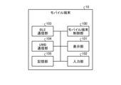
- FIG. 1 is a schematic diagram showing the configuration of an example of a communication system applicable to an embodiment of the present disclosure.
- FIG. 2 is a sequence diagram illustrating an example of payment processing by a parking lot fee payment system using short-range wireless communication according to existing technology.
- FIG. 2 is a schematic diagram illustrating an example of a user's burden in a parking lot fee payment process using existing technology.
- FIG. 2 is a schematic diagram for explaining that it is difficult to select and connect a specific device from an unspecified number of devices in communication using BLE according to existing technology.
- FIG. 3 is a schematic diagram for explaining communication processing according to the embodiment.
- FIG. 2 is a schematic diagram for explaining the principle of distance measurement using UWB.
- FIG. 2 is a block diagram showing the configuration of an example of a mobile terminal applicable to the embodiment.
- FIG. 2 is an example functional block diagram for explaining the functions of the mobile terminal according to the embodiment.
- FIG. 2 is a block diagram showing the configuration of an example of a parking lot payment terminal applicable to the embodiment. It is a functional block diagram of an example for demonstrating the function of the parking lot payment terminal based on embodiment.
- FIG. 3 is a sequence diagram illustrating an example of typical connection processing using a combination of UWB and BLE.
- FIG. 2 is a schematic diagram showing an example of the positional relationship between a mobile terminal and a parking lot payment terminal at each stage of a typical connection process using a combination of UWB and BLE. It is a schematic diagram for explaining a parking lot fee payment zone.
- FIG. 1 is an example functional block diagram for explaining the functions of the mobile terminal according to the embodiment.
- FIG. 2 is a block diagram showing the configuration of an example of a parking lot payment terminal applicable to the embodiment. It is a functional block diagram of an example for demonstrating the function of the parking lot payment terminal based on embodiment.
- FIG. 3 is a sequence diagram illustrating an example of processing in which a parking lot payment terminal performs UWB ranging for a large number of mobile terminals.
- FIG. 2 is a schematic diagram showing a packet structure of a link layer in BLE.
- FIG. 2 is a schematic diagram showing frequency bands allocated to UWB communication.
- FIG. 2 is a schematic diagram illustrating connection of UWB devices when a general pedestrian passage exists in the vicinity of a parking lot payment terminal.
- FIG. 2 is a schematic diagram illustrating connection of UWB devices when a general pedestrian passage exists in the vicinity of a parking lot payment terminal.
- FIG. 2 is a schematic diagram for explaining that communication with a parking lot payment terminal of a vehicle is delayed due to the presence of a large number of mobile terminals outside the vehicle.
- FIG. 2 is a schematic diagram for explaining that communication with a parking lot payment terminal of a vehicle is delayed due to the presence of a large number of mobile terminals outside the vehicle.
- FIG. 7 is an example sequence diagram showing BLE reconnection processing when there is one connection target according to the embodiment.
- FIG. 7 is an example sequence diagram showing BLE reconnection processing when a plurality of connection targets are connected according to the embodiment.
- It is a schematic diagram which shows the example of a structure of the 2nd UUID value based on embodiment.
- FIG. 3 is a schematic diagram showing an example of a dialog screen for confirming connection permission, which is applicable to the embodiment.
- FIG. 2 is a schematic diagram showing an example configuration of a packet ADV_NONCONN_IND applicable to the embodiment.
- FIG. 2 is an example flowchart illustrating a process for determining whether a mobile terminal is in a vehicle, according to an embodiment.
- FIG. 2 is a schematic diagram showing an example configuration of a packet ADV_NONCONN_IND applicable to the embodiment.
- 2 is a flowchart of an example of control of a mobile terminal based on a vehicle riding state according to an embodiment.
- FIG. 3 is a schematic diagram for explaining that the number of UWB devices targeted for UWB ranging is limited by the processing according to the embodiment.
- FIG. 3 is a schematic diagram for explaining that the number of UWB devices targeted for UWB ranging is limited by the processing according to the embodiment.
- FIG. 1 is a schematic diagram for explaining the architecture of a mobile terminal according to an embodiment.
- FIG. 1 is a schematic diagram showing the configuration of an example of a communication system applicable to an embodiment of the present disclosure. Below, an example in which the communication system according to the present disclosure is applied to a parking lot fee payment system that performs communication for payment of parking lot fees will be described.
- the parking lot payment system 1 includes a mobile terminal 10, a parking lot payment terminal 20 as a fixed terminal, and a payment server 30.
- the parking lot payment terminal 20 is communicably connected to the payment server 30 via a network 2 such as the Internet.
- the mobile terminal 10 is, for example, a terminal device carried by an occupant of a vehicle using a parking lot.
- an information processing device such as a smartphone or a tablet terminal that is easily portable and capable of wireless communication using a predetermined method can be applied.
- the parking lot payment terminal 20 sends an instruction to the gate barrier 21 in response to a payment operation by a user (for example, an occupant of a vehicle using the parking lot), and controls the opening and closing of the gate bar 21a.
- a user for example, an occupant of a vehicle using the parking lot
- the user may perform the payment operation by directly operating the controls provided on the parking lot payment terminal 20, or the user may install an NFC card having an NFC (Near Field radio Communication) function in the parking lot payment terminal 20. Payment operations may also be performed by holding the device over an NFC reader provided.
- the payment operation for the parking lot payment terminal 20 is performed using the mobile terminal 10. That is, the parking lot payment system 1 according to the embodiment performs a payment operation using the mobile terminal 10 through wireless communication between the mobile terminal 10 in the vehicle using the parking lot and the parking lot payment terminal 20. Realize.
- the parking lot payment terminal 20 communicates with the mobile terminal 10 using a first communication method using wireless communication, generates unique identification information, transmits it to the mobile terminal 10, and temporarily disconnects the communication. do.
- the parking lot payment terminal 20 detects that the mobile terminal 10 has entered a predetermined parking lot fee payment zone determined by the parking lot payment terminal 20 after the communication with the mobile terminal 10 is cut off, the parking lot payment terminal 20 starts communication with the mobile terminal 10 .
- the communication using the first communication method is reconnected between the mobile terminal 10 and the mobile terminal 10, and the information necessary for payment is transmitted and received to and from the mobile terminal 10, and the payment operation is performed.
- the parking lot payment terminal 20 opens the gate bar 21a and allows the vehicle including the mobile terminal 10 to leave the parking lot or enter the parking lot.
- the user can, for example, hold the NFC card over the NFC reader of the parking lot payment terminal 20 or go out of the vehicle and operate the controls on the parking lot payment terminal 20. It becomes possible to pay the parking fee while sitting in the parking lot.
- the first communication method mentioned above is BLE (Bluetooth Low Energy), which is one of the extended specifications of Bluetooth (registered trademark), which is a short-range wireless communication technology, and enables communication with extremely low power. may be applied. Further, detection of entry of the mobile terminal 10 into the parking fee payment zone may utilize distance measurement through communication using an ultra wide band wireless system (hereinafter referred to as UWB). The distance measuring method using UWB will be described later.
- BLE Bluetooth Low Energy
- UWB ultra wide band wireless system
- the parking lot fee payment terminals in the existing technology in addition to payment by cash, there are some that perform parking fee payment by short-range wireless communication using a mobile terminal owned by the user or an NFC card.
- the user refers to a passenger of a vehicle, such as a driver or a fellow passenger riding in the vehicle.
- An NFC card has a processor, memory, transmitting/receiving circuit, and antenna circuit configured in a card-like case, and is configured to perform communication using NFC (Near Field Radio Communication). By tapping or holding the NFC card over the NFC reader, the user can cause the NFC card and the NFC reader to communicate.
- NFC Near Field Radio Communication
- FIG. 2 is a sequence diagram of an example of payment processing by a parking lot fee payment system using short-range wireless communication according to existing technology.
- the parking lot payment system shown in FIG. 2 includes an NFC terminal 10a and a parking lot payment terminal 20a.
- the NFC terminal 10a and the parking lot payment terminal 20a correspond to the parking lot payment terminal 20 and the mobile terminal 10 shown in FIG. 1, respectively.
- the NFC terminal 10a is a terminal capable of communication using NFC, and is a mobile terminal having the above-mentioned NFC card or an NFC card emulation function.
- Parking lot payment terminal 20a includes a payment control section 2200 and an NFC reader 2210.
- the NFC reader 2210 performs short-range wireless communication with the NFC terminal 10a that has approached within a certain distance.
- the payment control unit 2200 performs payment processing for parking fees by communicating with a payment server (not shown), for example, in response to communication with the NFC terminal 10a by the NFC reader 2210 or direct operation by the user (such as inserting cash). .
- the parking lot payment terminal 20a detects the arrival of the vehicle 40 in step S1000.
- the gate bar 21a is in a closed state, and the vehicle 40 cannot pass through the gate barrier 21.
- the parking lot payment terminal 20a starts payment processing in response to the detection of the arrival of the vehicle 40 (step S1001).
- the user in the vehicle 40 opens a window on the NFC reader 2210 side of the vehicle 40, approaches the NFC reader 2210 with the NFC terminal 10a, and taps the NFC reader 2210 (step S1002).
- step S1001 When the payment process is started in step S1001, the NFC reader 2210 performs discovery on the tapped NFC terminal 10a (step S1003), and the NFC terminal 10a performs discovery on the NFC reader 2210 in response to this discovery. and returns a response (step S1004). As a result, a communication connection is established between the NFC reader 2210 and the NFC terminal 10a, and the parking lot fee payment communication sequence in step S1005 can be executed.
- step S1005 If the payment processing communication in step S1005 is successful, the NFC reader 2210 passes a payment status (OK) indicating this to the payment control unit 2200.
- the payment control unit 2200 issues an instruction to the gate barrier 21 to open the gate according to the payment status.
- the gate barrier 21 opens the gate bar 21a in response to this instruction. This allows the vehicle 40 to pass through the gate barrier 21.
- the parking lot fee payment process using the existing technology described above may place a burden on the user. That is, in order to hold (or tap) the NFC terminal 10a over the parking lot payment terminal 20a (NFC reader 2210), the window of the vehicle 40 needs to be opened or the user needs to step out of the vehicle and perform the operation.
- FIG. 3 is a schematic diagram for explaining an example of the burden on the user in the parking lot fee payment process using the existing technology.
- the parking lot payment terminal 20a is installed corresponding to a right-hand drive vehicle
- the vehicle 40 is a right-hand drive vehicle
- the user can open the window of the vehicle 40 as shown in section (a) of FIG.
- the user opens the NFC terminal 10a and holds the NFC terminal 10a over the NFC reader 2210.
- section (b) of FIG. 3 in the vehicle 40L, which is a left-hand drive vehicle, it is difficult for the user in the driver's seat to hold the NFC terminal 10a over the NFC reader 2210. This is particularly noticeable when the vehicle 40L is wide or has a low height.
- BLE's communication protocol due to the nature of BLE's communication protocol, it is difficult to select and connect a specific device from an unspecified number of devices, and the mobile terminal in the vehicle 40 located immediately in front of the parking lot payment terminal 20a It is difficult to guarantee connection with For example, when there are multiple devices capable of BLE communication in the surrounding area, such as a vehicle following the vehicle 40 that is just in front of the parking lot payment terminal 20a, or other pedestrians around the parking lot payment terminal 20a, the parking lot payment terminal 20a , it becomes extremely difficult to identify the communication target.
- FIG. 4 is a schematic diagram for explaining that it is difficult to select and connect a specific device from an unspecified number of devices in communication using BLE according to the existing technology.
- each user of a vehicle 40 2 in front of the parking lot payment terminal 20a, a vehicle 40 1 following the parking lot payment terminal 20a, and a vehicle 40 3 in front of the parking lot payment terminal 20a is connected to a mobile terminal 10b capable of BLE communication. 2 , 10b 1 and 10b 3 .
- the BLE communication unit 2211 of the parking lot payment terminal 20a it is difficult for the BLE communication unit 2211 of the parking lot payment terminal 20a to designate and connect to a specific terminal from the mobile terminals 10b 1 to 10b 3 .
- BLE connection is permitted on the condition that a payment application installed in the mobile terminal for executing payment using BLE communication is activated in advance. This makes it possible to reduce the number of BLE communicable devices around the parking lot payment terminal 20a and improve the probability of pairing the parking lot payment terminal with the correct mobile terminal.
- the BLE communication unit 2211 may mistakenly connect to a mobile terminal located in the vehicle 40 1 behind or in the oncoming lane, instead of the vehicle 40 2 located immediately in front of the parking lot payment terminal 20a. In this case, the vehicle 40 2 will not be able to enter or exit the parking lot correctly.
- the location of the mobile terminal 10 is specified by the parking lot payment terminal 20 using a communication means having a high-precision ranging function, such as UWB.
- the mobile terminal 10 specifies the location of the parking lot payment terminal 20 using the communication means.
- the parking lot payment terminal 20 can limit communication to the mobile terminal 10 in the vehicle 40 located immediately in front of the parking lot payment terminal 20.
- FIG. 5 is a schematic diagram for explaining communication processing according to the embodiment.
- the parking lot payment terminal 20 includes a mobile communication unit 22 that is capable of communication using BLE as a first communication method and communication using UWB as a second communication method.
- BLE BLE
- UWB UWB
- the mobile communication unit 22 is a peripheral device in BLE
- each of the mobile terminals 10 1 to 10 3 is a central device.
- the parking lot payment terminal 20 uses the mobile communication unit 22 to perform advertisement in BLE.
- the nearby mobile terminals 10 1 to 10 3 receive this advertisement, they return a response to the received advertisement to the mobile communication unit 22.
- advertisement scans by the mobile terminals 10 1 to 10 3 are executed at arbitrary timings. Therefore, one of the mobile terminals 10 1 to 10 3 that was able to receive the advertisement in a timely manner returns a response and is connected to the parking lot payment terminal 20.
- the parking lot payment terminal 20 generates and transmits unique identification information to the connected mobile terminal. Furthermore, the parking lot payment terminal 20 exchanges parameters used for UWB communication (referred to as UWB setting parameters) with a simultaneously connected mobile terminal. When the necessary BLE communication is completed, the BLE connection between the parking lot payment terminal 20 and the mobile terminal is temporarily disconnected. When the exchange of UWB setting parameters is completed, the parking lot payment terminal 20 causes the mobile communication unit 22 to perform ranging by UWB communication to the mobile terminal with which the UWB setting parameters have been exchanged.
- UWB setting parameters parameters used for UWB communication
- the parking lot payment terminal 20 selects the terminal closest to the mobile communication unit 22 (the mobile terminal 10 2 in the example of FIG. 5) among the mobile terminals 10 1 to 10 3 as the terminal for payment processing. Identify. The parking lot payment terminal 20 reconnects BLE to the specified mobile terminal 10 2 and executes communication for payment processing.
- the payment of the parking lot fee is thus performed by using a communication means having a high-precision ranging function in combination with a communication means for transmitting and receiving payment information.
- a parking lot fee payment system 1 that can provide a convenient touchless UX that does not require opening a window or holding down the mobile terminal 10 when paying a parking fee.
- FIG. 6 is a schematic diagram for explaining the principle of distance measurement using UWB.
- the initiator (corresponding to the mobile communication unit 22) transmits the UWB frame to the responder (corresponding to the mobile terminals 10 1 , 10 2 , 10 3 ).
- the responder After receiving the UWB frame, the responder includes the value of time t 2 in the UWB frame and transmits it to the initiator after a certain time t 2 has elapsed depending on the processing time and the like.
- the initiator measures the time t 1 from the time of transmitting the UWB frame to the responder to the time of receiving the UWB frame transmitted from the responder.
- distance measurement can be performed with an accuracy of about several cm to 20 cm using the distance measurement method described above.
- FIG. 7 is a block diagram showing the configuration of an example of the mobile terminal 10 applicable to the embodiment.
- the mobile terminal 10 includes a CPU (Central Processing Unit) 1000, a ROM (Read Only Memory) 1001, a RAM (Random Access Memory) 1002, an input control unit 1003, and a display control unit 1004. . Furthermore, the mobile terminal 10 includes a storage device 1005, a communication I/F 1006, a data I/F 1007, a BLE communication I/F 1008, and a UWB communication I/F 1009. These units included in the mobile terminal 10 are communicably connected to each other by a bus 1020.
- a bus 1020 a bus 1020.
- the storage device 1005 is a nonvolatile storage medium such as flash memory.
- the present invention is not limited to this, and a hard disk drive may be applied as the storage device 1005.
- CPU 1000 operates according to programs stored in storage device 1005 and ROM 1001, using RAM 1002 as a work memory, and controls the overall operation of mobile terminal 10.
- the input device 1013 is a device for receiving user operations, and outputs a signal depending on the position touched by the user, for example.
- Input control unit 1003 generates a control signal according to user operation based on the signal output from input device 1013, and passes the generated control signal to CPU 1000 via bus 1020.
- the display control unit 1004 generates a display signal compatible with the display device 1014 based on the display control information generated by the CPU 1000, and passes the generated display signal to the display device 1014.
- the display device 1014 displays a screen according to the display signal passed from the display control unit 1004.
- the input device 1013 and the display device 1014 may be integrally configured as a so-called touch panel that outputs a signal according to a user's operation on an operation screen displayed on the display device 1014.
- a communication I/F (interface) 1006 is an interface for performing wireless communication via a communication network such as the Internet under the control of the CPU 1000.
- the data I/F 1007 is an interface for transmitting and receiving data to and from an external device through wired communication, for example, under the control of the CPU 1000.
- the BLE communication I/F 1008 is an interface for performing wireless communication according to the BLE protocol under the control of the CPU 1000.
- the UWB communication I/F 1009 is an interface for performing wireless communication according to the UWB protocol under the control of the CPU 1000.
- the UWB communication I/F 1009 may perform processing related to distance measurement using UWB communication.
- FIG. 8 is an example functional block diagram for explaining the functions of the mobile terminal 10 according to the embodiment.
- the mobile terminal 10 includes a mobile terminal control section 100, a display section 101, an input section 102, a BLE communication section 103, a UWB communication section 104, and a storage section 105.
- These mobile terminal control section 100, display section 101, input section 102, BLE communication section 103, UWB communication section 104, and storage section 105 are configured by the payment program according to the embodiment running on the CPU 1000.
- the present invention is not limited to this, and hardware circuits that operate in cooperation with some or all of the mobile terminal control unit 100, display unit 101, input unit 102, BLE communication unit 103, UWB communication unit 104, and storage unit 105 It may also be configured by Note that the payment program is sometimes called a payment application program or a payment application.
- the mobile terminal control unit 100 controls the overall operation of this mobile terminal 10.
- the display unit 101 generates display control information, for example, and controls the screen display on the display device 1014.
- the input unit 102 receives user operations on the input device 1013 and generates control information according to the user operations.
- the BLE communication unit 103 controls the BLE communication I/F 1008 to execute communication as a BLE central device.
- the UWB communication unit 104 controls the UWB communication I/F 1009, performs communication as a UWB responder, and performs distance measurement.
- the storage unit 105 controls reading and writing of data to and from the storage device 1005 and the RAM 1002.
- the present invention is not limited to this, and the storage unit 105 may control reading and writing of data to a register included in the CPU 1000, for example.
- the storage unit 105 reading and writing data to and from the storage device 1005 and the RAM 1002 will be described as, for example, the storage unit 105 reading and writing data.
- the CPU 1000 executes the payment application according to the embodiment, thereby controlling the above-mentioned mobile terminal control section 100, display section 101, input section 102, BLE communication section 103, UWB communication section 104, and storage section 105. are configured as modules on the main storage area of the RAM 1002, respectively.
- the payment application can be acquired from the outside via a network such as the Internet and installed on the mobile terminal 10 through communication via the communication I/F 1006.
- the present invention is not limited to this, and the payment application may be provided from outside via the data I/F 1007. Further, the payment application may be provided while being stored in a removable storage medium such as a CD (Compact Disk), a DVD (Digital Versatile Disk), or a USB (Universal Serial Bus) memory.
- a removable storage medium such as a CD (Compact Disk), a DVD (Digital Versatile Disk), or a USB (Universal Serial Bus) memory.
- FIG. 9 is a block diagram showing the configuration of an example of the parking lot payment terminal 20 applicable to the embodiment.
- the parking lot payment terminal 20 includes a CPU 2000, a ROM 2001, a RAM 2002, an input control section 2003, and a display control section 2004. Furthermore, the parking lot payment terminal 20 includes a storage device 2005, a communication I/F 2006, a gate communication I/F 2007, a BLE communication I/F 2008, and a UWB communication I/F 2009. These units included in the parking lot payment terminal 20 are connected to each other by a bus 2020 so as to be able to communicate with each other.
- the storage device 2005 is a nonvolatile storage medium such as a flash memory or a hard disk drive.
- CPU 2000 operates according to programs stored in storage device 2005 and ROM 2001, using RAM 2002 as a work memory, and controls the overall operation of parking lot payment terminal 20.
- the input device 2013 is a device for receiving user operations, includes an operator such as a button or a touch pad, and outputs a signal according to the user operation.
- the input control unit 2003 generates a control signal according to a user's operation based on the signal output from the input device 2013, and passes the generated control signal to the CPU 2000 via the bus 2020.
- the display control unit 2004 generates a display signal compatible with the display device 2014 based on the display control information generated by the CPU 2000, and passes the generated display signal to the display device 2014.
- the display device 1014 displays a screen or a sign according to the display signal passed from the display control unit 2004.
- the input device 2013 and the display device 2014 may be integrally configured as a so-called touch panel that outputs a signal according to a user's operation on an operation screen displayed on the display device 2014.
- the communication I/F 2006 is an interface for performing wireless communication via a communication network such as the Internet under the control of the CPU 2000.
- Gate communication I/F 2007 is an interface for communicating with gate barrier 21 under the control of CPU 2000.
- the BLE communication I/F 2008 is an interface for performing wireless communication according to the BLE protocol under the control of the CPU 2000.
- the UWB communication I/F 2009 is an interface for performing wireless communication according to the UWB protocol under the control of the CPU 2000.
- the UWB communication I/F 2009 may perform processing related to distance measurement using UWB communication.
- the mobile communication unit 22 shown in FIG. 5 is configured by the BLE communication I/F 2008 and the UWB communication I/F 2009.
- FIG. 10 is an example functional block diagram for explaining the functions of the parking lot payment terminal 20 according to the embodiment.
- the parking lot payment terminal 20 includes a payment terminal control unit 200, a display unit 201, an input unit 202, a BLE communication unit 203, a UWB communication/distance measurement unit 204, a gate communication unit 205, and a payment It includes a communication section 206, a payment processing section 207, and a storage section 208.
- the payment terminal control section 200 displays section 201, input section 202, BLE communication section 203, UWB communication/distance measurement section 204, gate communication section 205, payment communication section 206, payment processing section 207, and storage section 208 are installed on the CPU 2000.
- the payment control program according to the embodiment operates in this manner.
- the present invention is not limited to this, but includes the payment terminal control unit 200, display unit 201, input unit 202, BLE communication unit 203, UWB communication/distance measurement unit 204, gate communication unit 205, payment communication unit 206, payment processing unit 207, and storage unit.
- Some or all of 208 may be configured by hardware circuits that operate in cooperation with each other.
- the payment terminal control unit 200 controls the entire operation of this parking lot payment terminal 20.
- the display unit 201 generates display control information, for example, and controls display on the display device 2014.
- the input unit 202 receives user operations on the input device 2013 and generates control information according to the user operations.
- the BLE communication unit 203 controls the BLE communication I/F 2008 to execute communication as a BLE peripheral device.
- the UWB communication/distance measurement unit 204 controls the UWB communication I/F 2009, performs communication as a UWB initiator, and executes distance measurement.
- the gate communication unit 205 controls the opening and closing of the gate bar 21a by the gate barrier 21 via the gate communication I/F 2007.
- the payment communication unit 206 controls the communication I/F 2006 to communicate with the payment server 30, for example.
- the payment processing unit 207 executes payment processing with the mobile terminal 10 based on information acquired from the mobile terminal 10 by the BLE communication unit 203, for example.
- the payment processing unit 207 may transmit the processing result of the payment process to the payment server 30 using the payment communication unit 206, for example.
- the storage unit 208 controls reading and writing of data to and from the storage device 2005 and RAM 2002.
- the storage unit 208 is not limited to this, and may control reading and writing of data to a register included in the CPU 2000, for example.
- the storage unit 208 reading and writing data to and from the storage device 2005 and the RAM 2002 will be described as, for example, the storage unit 208 reading and writing data.
- the CPU 2000 executes the payment control program according to the embodiment, thereby controlling the payment terminal control section 200, display section 201, input section 202, BLE communication section 203, and UWB communication/distance measurement described above.
- the unit 204, the gate communication unit 205, the payment communication unit 206, the payment processing unit 207, and the storage unit 208 are each configured as a module, for example, on the main storage area of the RAM 2002.
- the payment control program can be acquired from the outside via a network such as the Internet by communication via the communication I/F 2006, and can be installed on the parking lot payment terminal 20.
- the payment control program may be provided externally via a data I/F (not shown).
- the payment control program may be provided while being stored in a removable storage medium such as a CD (Compact Disk), a DVD (Digital Versatile Disk), or a USB (Universal Serial Bus) memory.
- a UWB device that communicates using UWB consumes more power than a BLE device that communicates using BLE, for example. Therefore, when using a UWB device in a battery-powered device such as the mobile terminal 10, in order to reduce the power consumption of the UWB device, an out-of-band method is used to start the UWB device and share UWB communication setting parameters. ) It is common to use communication by a BLE device as a communication path.
- the mobile terminal 10 which may perform BLE communication for multiple purposes at the same time, operates as a central device, and the parking lot payment terminal 20 operates as a peripheral device.
- the parking lot payment terminal 20 which is a peripheral device, to simultaneously connect and communicate with multiple central devices (mobile terminals 10) in parallel.
- peripheral devices cannot control communication timing, when a peripheral device connects and communicates with multiple central devices in parallel, the wireless communication timing may conflict with the multiple central devices and communication errors may occur. be. Therefore, a peripheral device generally communicates with only one central device.
- FIG. 11 is an example sequence diagram showing an example of typical connection processing using a combination of UWB and BLE.
- FIG. 12 is a schematic diagram showing an example of the positional relationship between the mobile terminal 10 (vehicle 40) and the parking lot payment terminal 20 at each stage of a typical connection process using a combination of UWB and BLE.
- step S100 the parking lot payment terminal 20 searches for the mobile terminal 10 by transmitting a BLE advertising packet ADV_IND (hereinafter referred to as packet ADV_IND).
- packet ADV_IND a BLE advertising packet
- the mobile terminal 10 returns a connection request packet CONNECT_IND (hereinafter referred to as packet CONNECT_IND) to the parking lot payment terminal 20 (step S101).
- step S101 As shown in section (a) of FIG. 12, the vehicle 40 including the mobile terminal 10 is on its way to the parking lot payment terminal 20.
- the parking lot payment terminal 20 establishes a BLE connection with the mobile terminal 10 that responded to the packet ADV_IND.
- the parking lot payment terminal 20 and the mobile terminal 10 exchange UWB setting parameters using the BLE communication channel.
- the UWB setting parameters exchanged here are parameters necessary to perform distance measurement by UWB, and include at least the session ID and address information of the partner device (MAC address (Media Access Control address), etc.).
- step S102 As shown in section (b) of FIG. 12, the vehicle 40 including the mobile terminal 10 is on its way to the parking lot payment terminal 20, compared to the time of step S101 described above. , is approaching the parking lot payment terminal 20.
- the parking lot payment terminal 20 and the mobile terminal 10 respectively activate the UWB devices (for example, UWB communication I/Fs 1009 and 2009) in steps S103a and S103b.
- the UWB devices for example, UWB communication I/Fs 1009 and 2009
- step S104 the parking lot payment terminal 20 performs UWB communication with the mobile terminal 10 and starts distance measurement using UWB.
- distance measurement using UWB may be referred to as UWB ranging.
- step S104 the vehicle 40 including the mobile terminal 10 is still on its way to the parking lot payment terminal 20, compared to the time of step S102 described above. , and is closer to the parking lot payment terminal 20. Furthermore, the parking lot payment terminal 20 measures the distance to the vehicle 40 (mobile terminal 10) using UWB ranging.
- the parking lot payment terminal 20 When the parking lot payment terminal 20 detects by UWB ranging that the mobile terminal 10 has entered the specified range (parking lot fee payment zone) where the parking lot payment terminal 20 performs payment communication (step S105), the parking lot payment terminal 20 uses the BLE communication channel. The payment communication is performed using (step S106).
- FIG. 13 is a schematic diagram for explaining the parking lot payment zone. As shown in FIG. 13, the area within a predetermined radius R around the mobile communication unit 22 is defined as the parking lot fee payment zone 50.
- the parking lot payment terminal 20 determines whether the mobile terminal 10 is entering the parking lot fee payment zone 50 based on the distance to the mobile terminal 10 measured by UWB ranging by the mobile communication unit 22.
- Section (d) of FIG. 12 shows the vehicle 40 (mobile terminal 10) entering the parking lot payment zone 50 and arriving just in front of the parking lot payment terminal 20.
- the vehicle 40 temporarily stops, for example, at a position immediately in front of the parking lot payment terminal 20, and waits for the payment communication to normally end.
- step S106 When the payment communication in step S106 ends normally, the UWB and BLE connections between the parking lot payment terminal 20 and the mobile terminal 10 are disconnected (step S107). After the process in step S107, the gate bar 21a is opened by controlling the gate barrier 21 of the parking lot payment terminal 20, and as shown in section (e) of FIG. You can enter the venue or enter from the parking lot.
- This problem can be solved by the parking lot payment terminal 20 performing BLE and UWB communication with a plurality of mobile terminals 10 in the surrounding area to search for and connect to a mobile terminal 10 that can be the target of payment communication.
- UWB ranging can be performed with all mobile terminals 10 around the parking lot payment terminal 20 that may be subject to payment communication.
- the parking lot payment terminal 20 is a peripheral device in BLE, it is difficult to perform BLE communication with multiple mobile terminals 10 at the same time, as described above. Although it is possible to install a large number of BLE peripheral devices in the parking lot payment terminal 20, this is not economically rational and cannot be said to be realistic.
- the parking lot payment terminal 20 performs UWB ranging for one mobile terminal 10 according to the sequence explained using FIG.
- a possible method is to disconnect the BLE connection and then search for other mobile terminals 10 by advertising BLE again.
- FIG. 14 is an example sequence diagram showing an example of a process in which the parking lot payment terminal 20 performs UWB ranging on a large number of mobile terminals 10.
- step S200a-1 to step S205-1 is the same as the processing from step S100 to step S104 described using FIG.
- the parking lot payment terminal 20 searches for mobile terminals 10 1 , 10 2 , 10 3 , . . . by transmitting the BLE packet ADV_IND.
- the mobile terminal 10 1 among the mobile terminals 10 1 , 10 2 , 10 3 , . . . returns a packet CONNECT_IND to the parking lot payment terminal 20 in response to the packet ADV_IND (step S201-1).
- the parking lot payment terminal 20 establishes a BLE connection with the mobile terminal 10 that responded to the packet ADV_IND.
- the parking lot payment terminal 20 and the mobile terminal 10 1 exchange UWB setting parameters using the BLE communication channel.
- the parking lot payment terminal 20 activates the UWB device in step S203.
- the mobile terminal 10 1 activates the UWB device in step S204-1.
- step S205-1 the parking lot payment terminal 20 performs UWB communication with the mobile terminal 10 and starts UWB ranging.
- UWB ranging is performed for the mobile terminal 10 1 by the UWB device of the parking lot payment terminal 20 (step S206-1).
- the parking lot payment terminal 20 transmits the operation code LL_TERMINATE_IND to the mobile terminal 10 1 and disconnects the BLE connection with the mobile terminal 10 1 (step S207-1).
- the parking lot payment terminal 20 After disconnecting the BLE connection with the mobile terminal 10 1 in step S207-1, the parking lot payment terminal 20 transmits the BLE packet ADV_IND again (step S200a-2, step S200b-2), and sends the BLE packet ADV_IND to another mobile terminal 10.
- a search for mobile terminals 10 2 , 10 3 , . . . in this example is started. For example, assume that the mobile terminal 10 2 returns a packet CONNECT_IND to the parking lot payment terminal 20 in response to this packet ADV_IND (step S201-1).
- UWB ranging for the mobile terminals 10 2 , 10 3 , . . . is executed by repeating the same processing as steps S202-1 to S207-1 described above.
- the parking lot payment terminal 20 executes UWB ranging for the mobile terminal 10 2 in the processing of steps S201-2 to S207-2, and 10 3 UWB ranging is being performed.
- the parking lot payment terminal 20 disconnects the BLE connection with the mobile terminal 10, searches for a plurality of mobile terminals 10 one after another, and performs UWB ranging. It becomes possible to perform ranging.
- the BLE connection by the parking lot payment terminal 20 to the mobile terminals 10 1 , 10 2 , 10 3 , . . . is generally performed in a random order. That is, in the example of FIG. 14, the mobile terminal 10 1 , the mobile terminal 10 2 , and the mobile terminal 10 3 are shown as being connected in this order, but this is for explanation; in reality, for example, each Any of the mobile terminals 10 1 to 10 3 may be connected first.
- the first issue is related to specifying a connection destination for BLE reconnection.
- the second issue is related to limiting the number of UWB devices that are targets of UWB ranging.
- the parking lot payment terminal 20 can connect to a desired mobile terminal 10 and perform UWB ranging according to the sequence shown in FIG. On the other hand, after detecting that the mobile terminal 10 has entered the parking lot payment zone 50 by UWB ranging, the parking lot payment terminal 20 reconnects with the mobile terminal 10 using BLE in order to perform payment communication. There is a need to do.
- BLE advertisement is basically a broadcast, and in normal usage, it is not possible to specify a specific device and reconnect. Therefore, in order to reconnect with BLE, it is necessary to specify the mobile terminal 10 in the parking lot payment zone 50 by some means.
- an advertisement packet ADV_DIRECT_IND (hereinafter referred to as a packet ADV_DIRECT_IND) defined in the Bluetooth (registered trademark) protocol is used. There is a way.
- Packet ADV_DIRECT_IND is transmitted when the peripheral device includes the address of the target central device in the packet ADV_DIRECT_IND when the Bluetooth Device Address (BD address) of the central device in Bluetooth is known. Only the device responds to enable connection with a specific device.
- BD address Bluetooth Device Address
- FIG. 15 is a schematic diagram showing the packet structure of the link layer in BLE.
- the link layer packet includes a 1-byte field PA, a 4-byte field Access Addr, followed by a 2-byte field HDR.
- Fields AdvA and TargetA of 6 bytes each are placed following field HDR, and a 3-byte CRC (Cyclic Redundancy Check) code is placed at the end.
- Fields AdvA and TargetA constitute the payload.
- Section (a) in FIG. 15 shows the configuration of field HDR.
- the field HDR includes an 8-bit field Length, 1-bit fields RxAdd, TxAdd, ChSel, and RFU, and finally a 4-bit field PDU Type.
- the field PDU Type stores information indicating the type of this PDU (Protocol Data Unit).
- the value of the field PDU Type is "0000b” indicating that this packet is a packet ADV_IND, and "0001b” indicates that this packet is a packet ADV_DIRECT_IND. Further, the value of the field PDU Type is "0010b", indicating that this packet is a packet ADV_NONCONN_IND.
- the value of the field PDU Type is "0001b". Further, in the payload, the address of the peripheral device is stored in the field AdvA, and the address of the central device is stored in the field Target.
- the address of the peripheral device stored in the field AdvA is the BD address of the parking lot payment terminal 20. Further, as the address of the central device, the BD address of the mobile terminal 10 designated as the connection partner is stored. The BD address of the mobile terminal 10 can be obtained, for example, from the packet CONNECT_IND responded to the packet ADV_IND in step S200a-1 in FIG. 14.
- the parking lot payment terminal 20 connects the mobile terminal when performing a BLE connection (first connection, for example, steps S200a-1 and S201-1 in FIG. 14) to start UWB ranging.
- a BLE connection first connection, for example, steps S200a-1 and S201-1 in FIG. 14
- the parking lot payment terminal 20 transmits a packet ADV_DIRECT_IND including the BD address in advertisement at the time of BLE reconnection. In this way, the parking lot payment terminal 20 can specify and connect to a desired mobile terminal 10 by using the packet ADV_DIRECT_IND.
- BLE devices such as mobile terminals and smart watches equipped with BLE communication functions use temporary random numbers (Random Address) for the BD address from the perspective of privacy protection. There are many. Furthermore, when random addresses are used, among the types of random addresses, dynamically updated addresses called private addresses are used.
- the private address is periodically updated in the BLE device. Therefore, depending on the timing of BLE reconnection, the BD address of the mobile terminal 10 may be updated from the BD address stored by the parking lot payment terminal 20 at the time of the first connection. In that case, the mobile terminal 10 cannot respond to the packet ADV_DIRECT_IND in which a BD address different from its own updated BD address is stored, so a situation arises in which reconnection cannot be established.
- the OS (Operating System) of the mobile terminal 10 currently in circulation often does not support the scanning function of the packet ADV_DIRECT_IND as a Bluetooth software API (Application Programming Interface). In this case, the packet ADV_DIRECT_IND cannot be used in the first place.
- ADV_DIRECT_IND which specifies and connects only one device, is difficult to handle.
- FIG. 16 is a schematic diagram showing frequency bands allocated to UWB communication.
- band groups 0 and 1 are defined as frequencies that are lower than the 5 GHz (gigahertz) frequency
- band group 2 is defined as a frequency band that is higher than the 5 GHz (gigahertz) frequency.
- the frequency band is 499.2 MHz (megahertz), and the frequency bands are determined so that the bands do not overlap.
- Group 1) and channels CH5, 6 and 8-14 (band group 2) are defined.
- channels with frequency bands of 1 GHz or more are defined as channel CH4 in band group 1, and channels CH7, 11, and 15 in band group 2, respectively.
- channels CH9 and CH10 are allocated as channels that can be used outdoors in Japan.
- channel CH10 is often not supported by UWB devices, and essentially only one channel, CH9, can be used.
- the procedure from the parking lot payment terminal 20 searching for a BLE mobile terminal 10 to starting UWB ranging is a sequential operation that is sequentially executed for each mobile terminal 10. . Therefore, after the parking lot payment terminal 20 connects with one mobile terminal 10 and starts UWB ranging, it takes a certain amount of time until it connects with the next mobile terminal 10 and starts UWB ranging.
- the area around the parking lot payment terminal 20 is a path for general pedestrians.
- a large number of mobile terminals 10 may be unexpectedly present around the parking lot payment terminal 20, such as a plurality of pedestrians passing on the traffic route each holding a mobile terminal 10.
- the parking lot payment terminal 20 establishes a UWB connection with the mobile terminal 10 held by a pedestrian passing through these traffic routes, due to restrictions on the number of UWB devices that can be connected, the mobile terminal 20 in the vehicle 40 that can be the subject of payment communication UWB connection with the terminal 10 may not be possible, and there is a risk that problems will occur when the vehicle 40 enters or exits the parking lot.
- FIGS. 17A and 17B are schematic diagrams for explaining the connection of UWB devices when a general pedestrian passage exists in the vicinity of the parking lot payment terminal 20.
- the left side of the boundary line 90 is a traffic route, and a plurality of pedestrians 60 each holding a mobile terminal 10 are passing through the traffic route. Further, it is assumed that the number of UWB devices that can be simultaneously connected to the parking lot payment terminal 20 is eight.
- a vehicle 40 including a mobile terminal 10 is moving towards a parking lot payment terminal 20.
- the parking lot payment terminal 20 is held by each of the plurality of pedestrians 60 who are passing through the traffic route.
- UWB connection is being made to the maximum number of mobile terminals 10 that can be connected simultaneously (eight indicated with diagonal lines in the figure).
- the mobile terminal 10 in the vehicle 40 cannot establish a UWB connection with the parking lot payment terminal 20, even though it has arrived just in front of the parking lot payment terminal 20. Therefore, the parking lot payment terminal 20 cannot detect the entry of the vehicle 40 into the parking lot fee payment zone 50, and cannot perform the subsequent parking fee payment process using BLE communication (see FIG. 11). .
- FIGS. 18A and 18B are schematic diagrams for explaining that communication with the parking lot payment terminal 20 of the vehicle 40 is delayed due to the presence of a large number of mobile terminals 10 outside the vehicle 40.
- the mobile terminal 10 of the vehicle 40 and the plurality of mobile terminals 10 held by the plurality of pedestrians 60 passing on the traffic route exist outside the BLE communication range 51 of the parking lot payment terminal 20. Think about what happens when you do. In the state shown in FIG. 18A, since both mobile terminals 10 are outside the BLE communication range 51, they are not connected to the parking lot payment terminal 20.
- the vehicle 40 has arrived just in front of the parking lot payment terminal 20, and the mobile terminal 10 inside the vehicle 40 has moved within the BLE communication range 51, and each of the mobile terminals 10 held by each pedestrian 60 has also moved. , shows a state of movement within the BLE communication range 51.
- connection by BLE is performed sequentially and in a random order for each mobile terminal 10. Therefore, there is a possibility that the mobile terminal 10 of each pedestrian 60 will be connected to the parking lot payment terminal 20 by BLE before the mobile terminal 10 in the vehicle 40 is connected by BLE.
- the mobile terminals 10 numbered 1 to 3 have completed connection through BLE advertisement and are connected via UWB, and the mobile terminal 10 number 4 is currently connected through BLE advertisement.
- the mobile terminal 10 in the vehicle 40 is not connected. That is, in this example, the connection process for the mobile terminal 10 in the vehicle 40 is started after the BLE connection of the mobile terminal 10 numbered 4 is completed, and it takes a long time until the payment process is executed and the gate bar 21a is opened. Become.
- the parking lot payment terminal 20 connects with the mobile terminal 10 by advertising BLE, exchanges UWB setting parameters, and performs UWB ranging.
- the parking lot payment terminal 20 reconnects with the mobile terminal 10 identified by UWB ranging through BLE communication. This series of processing will be specifically explained.
- FIG. 19 is an example sequence diagram illustrating BLE reconnection processing when there is one connection target according to the embodiment.
- step S300 the mobile terminal 10 starts scanning the first packet ADV_IND. Further, in step S301, the parking lot payment terminal 20 transmits the first packet ADV_IND and searches for the mobile terminal 10. At this time, the parking lot payment terminal 20 generates a first UUID (Universally Unique IDentifier) value, stores the generated first UUID value in the first packet ADV_IND, and transmits it.
- the method of generating the first UUID value by the parking lot payment terminal 20 is not particularly limited, but it is conceivable to allocate a UUID value to each payment application in advance.
- the first UUID value may be stored, for example, in the field ADV_DATA of the packet ADV_IND. Note that in the figure, the first UUID value is shown as UUID #1.
- the mobile terminal 10 In response to this packet ADV_IND, the mobile terminal 10 returns a packet CONNECT_IND to the parking lot payment terminal 20 (step S302).
- the parking lot payment terminal 20 establishes a BLE connection with the mobile terminal 10 that responded to the packet ADV_IND.
- the parking lot payment terminal 20 When the BLE connection with the mobile terminal 10 is completed, the parking lot payment terminal 20 generates a first identification information MID value that is identification information for identifying the mobile terminal 10 (step S303).
- the parking lot payment terminal 20 may, for example, generate the identification information MID value using a 4-byte random value.
- the parking lot payment terminal 20 transmits the generated first identification information MID value to the mobile terminal 10 (step S304).
- the first identification information MID value is shown as MID#1.
- the mobile terminal 10 When the mobile terminal 10 receives the first identification information MID transmitted from the parking lot payment terminal 20, it stores the received first identification information MID value as identification information that identifies itself (step S305).
- the mobile terminal 10 may store the first identification information MID value in the RAM 1002 or in the storage device 1005.
- the present invention is not limited to this, and the mobile terminal 10 may store the received first identification information MID value in a register included in the CPU 1000.
- the parking lot payment terminal 20 and the mobile terminal 10 exchange UWB setting parameters using the BLE communication channel (step S306).
- the parking lot payment terminal 20 and the mobile terminal 10 respectively activate the UWB devices in steps S307a and S307b.
- the parking lot payment terminal 20 When the UWB device is activated, the parking lot payment terminal 20 performs UWB communication with the mobile terminal 10 and starts UWB ranging (step S308). UWB ranging for the mobile terminal 10 by the UWB device of the parking lot payment terminal 20 is performed (step S309). When UWB ranging is started and executed, the parking lot payment terminal 20 transmits the operation code LL_TERMINATE_IND to the mobile terminal 10 and disconnects the BLE connection with the mobile terminal 10 (step S310).
- the mobile terminal 10 After disconnecting the BLE connection in step S310, the mobile terminal 10 starts scanning the second packet ADV_IND whose UUID value includes the first identification information MID value assigned to itself (step S311).
- This second packet ADV_IND includes a second UUID value, which will be described later, as a UUID value.
- the parking lot payment terminal 20 again transmits the first packet ADV_IND including the first UUID value in order to search for another mobile terminal 10 (step S312).
- the parking lot payment terminal 20 detects the mobile terminal 10 within the parking lot fee payment zone 50 by the UWB ranging started in step S308 (step S313).
- the parking lot payment terminal 20 stops transmitting the first packet ADV_IND and transmits the second packet ADV_IND (step S314).
- the parking lot payment terminal 20 generates a second UUID value that is different from the first UUID value described above, stores it in the second packet ADV_IND, and transmits it. Note that in the figure, the second UUID value is shown as UUID #2.
- the mobile terminal 10 receives the second packet ADV_IND transmitted from the parking lot payment terminal 20 (step S315).
- the mobile terminal 10 recognizes that the second UUID value stored in the received second packet ADV_IND includes the first identification information MID value stored in step S305, the mobile terminal 10 immediately sends the packet CONNECT_IND, for example. It is transmitted to the parking lot payment terminal 20 (step S316). As a result, BLE reconnection is performed between the parking lot payment terminal 20 and the mobile terminal 10.
- step S317 payment communication is performed between the parking lot payment terminal 20 and the mobile terminal 10 using the reconnected BLE communication.
- step S317 ends normally, the UWB and BLE connections between the parking lot payment terminal 20 and the mobile terminal 10 are disconnected (step S318).
- the parking lot payment terminal 20 specifies the mobile terminal 10 to be connected in the BLE connection for exchanging UWB setting parameters for UWB ranging.
- the first identification information of is transmitted to the mobile terminal 10, and when UWB ranging is started, the BLE connection is disconnected.
- the parking lot payment terminal 20 reconnects the mobile terminal 10 and BLE using the first identification information, and executes payment processing with the mobile terminal 10. . Therefore, cashless payments can be made while the occupants of the vehicle 40 remain in the vehicle.
- FIG. 20 is an example sequence diagram illustrating BLE reconnection processing when there are multiple connection targets according to the embodiment.
- the parking lot payment terminal 20 connects with two mobile terminals 10 1 and 10 2 (also shown as mobile terminal #1 and mobile terminal #2, respectively).
- the processing related to each mobile terminal 10 1 and 10 2 is the same as the processing described using FIG. 19, except for a part.
- the parking lot payment terminal 20 connects to the mobile terminal 10 1 first among the mobile terminals 10 1 and 10 2 .
- step S401 mobile terminals 10 1 and 10 2 start scanning the first packet ADV_IND, respectively. Further, in step S401, the parking lot payment terminal 20 transmits the first packet ADV_IND and searches for the mobile terminals 10 1 and 10 2 . At this time, the parking lot payment terminal 20 generates a first UUID value, stores the generated first UUID value in the first packet ADV_IND, and transmits it.
- the mobile terminal 10 1 In response to this packet ADV_IND, the mobile terminal 10 1 returns a packet CONNECT_IND to the parking lot payment terminal 20 (step S402).
- the parking lot payment terminal 20 establishes a BLE connection with the mobile terminal 10 1 that responded to the packet ADV_IND.
- the parking lot payment terminal 20 When the BLE connection with the mobile terminal 10 1 is completed, the parking lot payment terminal 20 generates a first identification information MID value that is identification information for identifying the mobile terminal 10 1 (step S403).
- the parking lot payment terminal 20 may, for example, generate the identification information MID value using a 4-byte random value.
- the parking lot payment terminal 20 transmits the generated first identification information MID value to the mobile terminal 10 1 (step S404).
- the first identification information MID value is shown as MID#1.
- the mobile terminal 10 1 When the mobile terminal 10 1 receives the first identification information MID transmitted from the parking lot payment terminal 20, it stores the received first identification information MID value as identification information for identifying itself (step S405).
- the mobile terminal 10 1 may store the first identification information MID value in the RAM 1002 or in the storage device 1005.
- the present invention is not limited to this, and the mobile terminal 10 1 may store the received first identification information MID value in a register included in the CPU 1000.
- the parking lot payment terminal 20 and the mobile terminal 10 1 exchange UWB setting parameters using the BLE communication channel (step S406).
- the parking lot payment terminal 20 and the mobile terminal 10 1 activate their respective UWB devices in steps S407a and S407b.
- the parking lot payment terminal 20 When the UWB device is activated, the parking lot payment terminal 20 performs UWB communication with the mobile terminal 10 1 and starts UWB ranging (step S408). UWB ranging for the mobile terminal 10 1 is performed by the UWB device of the parking lot payment terminal 20 (step S409). When UWB ranging is started and executed, the parking lot payment terminal 20 transmits the operation code LL_TERMINATE_IND to the mobile terminal 10 1 and disconnects the BLE connection with the mobile terminal 10 1 (step S410).
- the mobile terminal 10 1 After the mobile terminal 10 1 disconnects the BLE connection in step S410, the mobile terminal 10 1 starts scanning the second packet ADV_IND whose UUID value includes the first identification information MID value assigned to itself (step S411).
- This second packet ADV_IND includes a second UUID value, which will be described later, as a UUID value.
- the parking lot payment terminal 20 transmits the first packet ADV_IND including the first UUID value again in order to search for another mobile terminal 10 2 (step S412a, step S412b).
- the mobile terminal 10 2 In response to this packet ADV_IND, the mobile terminal 10 2 returns a packet CONNECT_IND to the parking lot payment terminal 20 (step S413).
- the parking lot payment terminal 20 establishes a BLE connection with the mobile terminal 10 2 that responded to the packet ADV_IND.
- the parking lot payment terminal 20 When the BLE connection with the mobile terminal 10 2 is completed, the parking lot payment terminal 20 generates a second identification information MID value that is identification information for identifying the mobile terminal 10 2 .
- the parking lot payment terminal 20 may, for example, generate the second identification information MID value using a 4-byte random value.
- the parking lot payment terminal 20 transmits the generated second identification information MID value to the mobile terminal 10 2 (step S415).
- the second identification information MID value is shown as MID#2.
- the mobile terminal 102 Upon receiving the second identification information MID transmitted from the parking lot payment terminal 20 , the mobile terminal 102 stores the received second identification information MID value as identification information that identifies itself, similarly to step S405. do.
- the parking lot payment terminal 20 and the mobile terminal 10 2 exchange UWB setting parameters using the BLE communication channel (step S417).
- the mobile terminal 10 2 activates the UWB device in step S418.
- the parking lot payment terminal 20 When the UWB device is activated, the parking lot payment terminal 20 performs UWB communication with the mobile terminal 10 2 and starts UWB ranging (step S419). UWB ranging is performed for the mobile terminal 10 2 by the UWB device of the parking lot payment terminal 20 (step S420). When UWB ranging is started and executed, the parking lot payment terminal 20 transmits the operation code LL_TERMINATE_IND to the mobile terminal 10 2 and disconnects the BLE connection with the mobile terminal 10 2 (step S421).
- the mobile terminal 10 2 After the mobile terminal 10 2 disconnects the BLE connection in step S421, the mobile terminal 10 2 starts scanning the second packet ADV_IND whose UUID value includes the first identification information MID value assigned to itself (step S422).
- This second packet ADV_IND includes a second UUID value, which will be described later, as a UUID value.
- the parking lot payment terminal 20 again transmits the first packet ADV_IND including the first UUID value in order to search for another mobile terminal 10 2 (steps S423a and S423b). Since the mobile terminal 10 2 is scanning the second packet ADV_IND, this first packet ADV_IND is not detected by the mobile terminal 10 2 .
- the parking lot payment terminal 20 detects the mobile terminals 10 1 and 10 2 within the parking lot payment zone 50 by the UWB ranging started in step S408 (step S424).
- the parking lot payment terminal 20 stops transmitting the first packet ADV_IND and transmits the second packet ADV_IND (step S425a, step S425b).
- the parking lot payment terminal 20 generates a second UUID value including the first identification information MID value generated in step S403 and the second identification information MID value generated in step S414.
- the parking lot payment terminal 20 stores a second UUID value including the first identification information MID value and the second identification information MID value in the second packet ADV_IND, and transmits the second packet ADV_IND.
- FIG. 21 is a schematic diagram showing an example of the configuration of the second UUID value according to the embodiment.
- a UUID value having a data length of 128 bits is divided into four blocks each having a data length of 32 bits.
- the parking lot payment terminal 20 stores an identification information MID value in each block according to the number of mobile terminals 10 detected in the parking lot payment zone 50. Sections (a) to (d) of FIG. Examples are shown in which information MID values (MID#1 to MID#3) and four identification information MID values (MID#1 to MID#4) are stored.
- the second UUID value includes a first identification information MID value stored in the mobile terminal 10 1 and a second identification information MID value stored in the mobile terminal 10 2 . Therefore, the second packet ADV_IND containing the second UUID value is received and recognized by each of the mobile terminals 10 1 and 10 2 (step S426a, step S426b).
- the plurality of mobile terminals 10 display an inquiry dialog screen for confirming permission to connect to the parking lot payment terminal 20.
- FIG. 22 is a schematic diagram showing an example of a dialog screen for confirming connection permission, which is applicable to the embodiment.
- a dialog screen 70 is displayed on the display device 1014 of the mobile terminal 10.
- the dialog screen 70 includes a message display area 71 and buttons 72 and 73.
- the message display area 71 for example, a message prompting the user to confirm permission to connect to the parking lot payment terminal 20 is displayed.
- the button 72 is a button for notifying that connection is permitted
- the button 73 is a button for notifying that connection is not permitted.
- the explanation returns to FIG. 20, and it is assumed that, for example, the button 72 is operated on the mobile terminal 101 and connection permission is confirmed (step S427).
- the mobile terminal 10 1 transmits a packet CONNECT_IND to the parking lot payment terminal 20 in response to the operation on the button 72 (step S428).
- BLE reconnection is performed between the parking lot payment terminal 20 and the mobile terminal 10 1 .
- the parking lot payment terminal 20 may only validate the packet CONNECT_IND that is received first.
- the parking lot payment terminal 20 connected to the mobile terminal 10 1 sends a packet ADV_NONCONN_IND to the mobile terminal 10 2 that has become a non-connection target in order to notify that another mobile terminal has already been connected. (Step S429).
- a UUID #2' value including a LOST_MID value (0xFFFFFF) and a second identification information MID value for identifying the mobile terminal 10 2 is stored as a UUID value.
- FIG. 23 is a schematic diagram showing the configuration of an example of a packet ADV_NONCONN_IND applicable to the embodiment. As shown in FIG. 23, a block in which a 32-bit LOST_MID value "0xFFFFFF" is stored is placed at the beginning, and then a 32-bit second identification information MID value (MID#2) is placed next. . For example, random numbers are stored in the remaining 64-bit block of the UUID value.
- the mobile terminal 10 2 When the mobile terminal 10 2 receives the packet ADV_NONCONN_IND including the LOST_MID value "0xFFFFFF" and the second identification information MID value for identifying itself, the mobile terminal 10 2 stops scanning the second packet ADV_IND (step S430).
- step S431 After the BLE reconnection, payment communication is performed between the parking lot payment terminal 20 and the mobile terminal 101 using the reconnected BLE communication (step S431).
- step S431 ends normally, the UWB and BLE connections between the parking lot payment terminal 20 and the mobile terminals 10 1 and 10 2 are disconnected (steps S432a and S432b).
- the parking lot payment system 1 even if a plurality of mobile terminals 10 are present around the parking lot payment terminal 20, cashless payment is possible while the occupants of the vehicle 40 are in the vehicle. Payment is possible.
- terminal determination within the vehicle 40 according to the embodiment of the present disclosure will be described. That is, below, a process corresponding to the above-mentioned second problem, which is the limitation on the number of UWB devices to be subjected to UWB ranging, in the parking lot fee payment system 1 according to the embodiment will be described.
- the mobile terminal 10 in the vehicle 40 responds to the first and/or second packet ADV_IND, and the mobile terminal 10 of the pedestrian does not respond to the first and/or second packet ADV_IND. is used to limit the number of UWB devices targeted for UWB ranging.
- the mobile terminal 10 is equipped with a mechanism that can determine whether or not the mobile terminal 10 is inside the vehicle 40, and the mobile terminal 10 outside the vehicle 40 receives the first message sent from the parking lot payment terminal 20. 1 and/or the second packet ADV_IND.
- FIG. 24 is a flowchart of an example of a process for determining whether the mobile terminal 10 is in the vehicle 40, according to the embodiment.
- step S500 identification information Vehicle ID for identifying the vehicle 40 is registered in the mobile terminal 10.
- the storage unit 105 stores the identification information Vehicle ID input by the user operation in a storage medium such as the RAM 1002, the storage device 1005, or a register included in the CPU 1000.
- Identification Information Vehicle ID may be registered in the mobile terminal 10 at the time of purchasing the vehicle 40, or each time the vehicle 40 is boarded. If the vehicle 40 is a borrowed vehicle such as a rental car, the identification information Vehicle ID may be registered when starting to use the vehicle 40.
- a beacon device using Bluetooth is installed inside the vehicle 40, and the beacon device periodically transmits a packet ADV_NONCONN_IND containing a message indicating that the packet is inside the vehicle 40.
- FIG. 25 is a schematic diagram showing the configuration of an example of a packet ADV_NONCONN_IND applicable to the embodiment.
- Data AD Type and identification information Vehicle ID are stored in the field ADV_DATA.
- Data AD Type is information indicating the type of subsequent data. In this example, the value of data AD Type is "0xFE", indicating that the following data is identification information Vehicle. Further, the identification information Vehicle has a data length of, for example, 8 bytes.
- step S501 the mobile terminal 10 starts scanning signals transmitted from the beacon device.
- the mobile terminal 10 periodically scans the signal transmitted from the beacon device and determines whether the packet ADV_NONCONN_IND including the identification information Vehicle ID has been received (step S502).
- step S503 the mobile terminal 10 sets the value of the vehicle riding state in the vehicle 40. Set it to a value indicating that it exists (set it to "TRUE”).
- step S504 the mobile terminal 10 It is set to a value indicating that it is not inside the vehicle 40 (set to "FALSE").
- the value of the vehicle riding state is stored, for example, by the storage unit 105 in a storage medium such as the RAM 1002, the storage device 1005, or a register included in the CPU 1000.
- step S505 the mobile terminal 10 stops scanning signals transmitted from the beacon device.
- step S506 the mobile terminal 10 determines whether a certain period of time (for example, a predetermined period of one minute or less) has elapsed. If the mobile terminal 10 determines that the certain period of time has not elapsed (step S506, "No"), the process returns to step S506.
- a certain period of time for example, a predetermined period of one minute or less
- step S506 determines that the certain period of time has elapsed (step S506, "Yes"), it returns the process to step S501 and resumes signal scanning.
- the mobile terminal 10 retains the value "TRUE” for the in-vehicle state when the mobile terminal 10 is in the vehicle 40, and maintains the value "FALSE” for the in-vehicle state when the mobile terminal 10 is not in the vehicle 40. ” will be retained.
- FIG. 26 is a flowchart of an example of control of the mobile terminal 10 based on the in-vehicle state according to the embodiment. Note that FIG. 26 is an example in which control based on the vehicle riding state is incorporated into the process described using FIG. 19.
- step S600 the mobile terminal 10 determines whether the value of the vehicle riding state that it stores is the value "TRUE". If the mobile terminal 10 determines that the value of the vehicle riding state is not the value "TRUE” (in this example, it is "FALSE") (step S600, "No"), the process returns to step S600. On the other hand, if the mobile terminal 10 determines that the value of the in-vehicle state is "TRUE" (step S600, "Yes"), the mobile terminal 10 moves the process to step S300 and scans the first packet ADV_IND. Start.
- the mobile terminal 10 executes the connection process using BLE and UWB with the parking lot payment terminal 20 when the value of the vehicle riding state is the value "TRUE".
- the mobile terminal 10 does not perform the connection process using BLE and UWB with the parking lot payment terminal 20. Therefore, in the embodiment, it is possible to limit the number of UWB devices targeted for UWB ranging.
- FIGS. 27A and 27B are schematic diagrams for explaining that the number of UWB devices targeted for UWB ranging is limited by the processing according to the embodiment.
- each mobile terminal 10 held by each pedestrian 60 on the left side of the boundary line 90 has a value of "FALSE" in the vehicle riding state. Therefore, each mobile terminal 10 does not connect to the parking lot payment terminal 20 using BLE and UWB according to the flowchart in FIG. 26 . In other words, for the parking lot payment terminal 20, this is synonymous with the fact that the mobile terminal 10 of each pedestrian 60 does not exist.
- the mobile terminal 10 1 in the vehicle 40 1 has the value "TRUE" in the in-vehicle state, and can connect to the parking lot payment terminal 20 by BLE and UWB according to the flowchart of FIG. 26. .
- the parking lot payment system 1 it is determined whether the mobile terminal 10 is in the vehicle 40 or not, and the mobile terminal 10 that is not in the vehicle 40 is connected to the parking lot payment terminal 20 using BLE. and excluded from connection by UWB. Therefore, it is possible to limit the number of UWB devices targeted for UWB ranging.
- connection processing using BLE and UWB can be performed between the parking lot payment terminal 20 and the mobile terminal 10 2 .
- the method for determining whether or not the mobile terminal 10 is in the vehicle 40 is not limited to the method using the signal transmitted from the beacon device described above. For example, based on information from an acceleration sensor installed in the mobile terminal 10, if the moving speed of the mobile terminal 10 exceeds 30 km/h, or if a unique acceleration of the vehicle 40 is detected, the mobile It may be determined that the terminal 10 is inside the vehicle 40. Further, it may be determined whether the mobile terminal 10 is within the vehicle 40 based on the movement speed information of the mobile terminal 10 using a GNSS (Global Navigation Satellite System) function installed in the mobile terminal 10.
- GNSS Global Navigation Satellite System
- the value of the vehicle riding state may be determined and acquired using the unlocking or locking operation of the door of the vehicle 40 as a trigger.
- FIG. 28 is a schematic diagram for explaining the architecture of the mobile terminal 10 according to the embodiment. In addition, in FIG. 28, only the parts deeply related to the embodiment are described.
- a UWB/BLE middleware 81 for realizing UWB and BLE functions operates on the OS 80, and a payment application 82 that executes payment processing according to the embodiment is executed on the UWB/BLE middleware 81.
- the OS 80 controls the operation of the BLE chip 84 that implements the BLE function as hardware through the BLE API (Application Programming Interface) 83, and acquires information from the BLE chip 84. Further, the OS 80 controls the operation of the UWB chip 86 that implements UWB functions as hardware, and acquires information from the UWB chip 86 via the UWB API 85.
- BLE API Application Programming Interface
- the display section 101, the input section 102, the storage section 105, and some of the functions of the mobile terminal control section 100 may be included in the OS 80.
- the BLE communication unit 103 may be included in the BLE API 83 and a part of the UWB/BLE middleware 81.
- the UWB communication unit 104 may be included in the UWB API 85 and a part of the UWB/BLE middleware 81.
- the mobile terminal control unit 100 may include the functionality of the payment application 82.
- the processing on the mobile terminal 10 side in the sequences shown in FIGS. 19 and 20 may be controlled by the UWB/BLE middleware 81.
- the UWB/BLE middleware 81 calls the BLE API 83 via the OS 80 in response to an instruction from the payment application 82 to start scanning the first packet ADV_IND, and further calls the UWB API 85 as necessary.
- the subsequent communication process with the parking lot payment terminal 20 may be executed.
- the payment application 82 may be resident or may be activated by the user as needed.
- a parking lot can provide convenient touchless UX without the need to open or shade windows when paying a parking lot fee using UWB and BLE.
- a fee payment system 1 can be realized.
- the scope of use of the technology according to the present disclosure is not limited to application to the parking lot fee payment system 1.
- the technology according to the present disclosure is applicable not only to the parking lot payment terminal 20 but also to other payment systems in which a plurality of devices within a fee payment zone are detected and selected to perform payment.
- the value of the vehicle in-vehicle state for identifying the mobile terminal 10 inside or outside the vehicle 40 is not limited to the vehicle 40, but can also be applied to the identification of some other facility, inside or outside the area, etc.
- a first communication unit that performs wireless communication using a first communication method; a first control unit that controls communication by the first communication unit; a fixed terminal comprising; a second communication unit that performs wireless communication using the first communication method; a second control unit that controls communication by the second communication unit; storage section and a mobile terminal comprising; including;
- the first control unit includes: generating identification information unique to the mobile terminal connected through communication of the first communication unit and transmitting it to the mobile terminal; disconnecting the connection with the mobile terminal after transmitting the identification information; specifying the mobile terminal using the identification information through communication of the first communication unit, and reconnecting to the mobile terminal;
- the second control unit includes: storing the identification information acquired through communication with the fixed terminal by the second communication unit in the storage unit; After the fixed terminal disconnects communication with the fixed terminal, the second communication unit reconnects with the fixed terminal in response to receiving identification information that matches the identification information stored in the storage unit.
- the fixed terminal is a third communication unit that performs communication using a second communication method that allows distance measurement to a communication partner under the control of the first control unit; Furthermore, The mobile terminal is a fourth communication unit that performs communication using the second communication method under the control of the second control unit; Furthermore, The fixed terminal is The third communication unit communicates with the fourth communication unit to measure the distance between the fixed terminal and the mobile terminal, and as a result of the distance measurement, the distance between the fixed terminal and the mobile terminal is measured. reconnecting to the mobile terminal detected within a predetermined distance range; The communication system according to (1) above.
- the fixed terminal is a payment communication department that communicates with a payment device that performs payment processing; Furthermore, The first control unit includes: transmitting and receiving information for performing the payment processing by the payment device to and from the mobile terminal through communication by the first communication unit to the reconnected mobile terminal; The communication system according to (1) or (2) above. (4) a first communication unit that performs wireless communication using a first communication method; a control unit that controls communication by the first communication unit; Equipped with The control unit includes: Generating identification information unique to the mobile terminal connected by the communication of the first communication unit and transmitting it to the mobile terminal, disconnecting the connection with the mobile terminal after transmitting the identification information; specifying the mobile terminal using the identification information through communication of the first communication unit and reconnecting to the mobile terminal; Fixed terminal.
- the control unit includes: reconnecting to the mobile terminal detected within a predetermined distance range as a result of the distance measurement by the second communication unit;
- the first communication method is BLE (Bluetooth Low Energy), and the second communication method is an ultra-wideband wireless system.
- the control unit includes: In response to the transmission of the identification information by the first communication unit, the second communication unit starts distance measurement to the mobile terminal, and the communication by the first communication unit to the mobile terminal is disconnected.
- the fixed terminal according to (5) or (6) above.
- the control unit includes: Sending and receiving information for payment with the reconnected mobile terminal by communication of the first communication unit, and when the payment is completed, communication by the first communication unit and the second communication unit. disconnecting the communication for said distance measurement by the communication unit of; The fixed terminal according to any one of (5) to (7) above.
- the control unit includes: connecting to the mobile terminal using a first identifier by the first communication unit; After the disconnection with the mobile terminal, the first communication unit performs the connection process again using the first identifier, reconnecting to the mobile terminal using a second identifier including one or more of the identification information; The fixed terminal according to any one of (4) to (8) above.
- the control unit includes: When communication using the second identifier becomes possible with another mobile terminal in response to communication due to the reconnection, a connection notification is sent from among the mobile terminal or the other mobile terminal. transmitting a connection failure notification to the terminal to which the connection notification was not sent; The fixed terminal according to (9) above. (11) The control unit includes: performing the connection through communication of the first communication unit with the mobile terminal in the vehicle as a target; The fixed terminal according to any one of (4) to (10) above.
- the control unit includes: transmitting and receiving information for performing the payment processing by the payment device to and from the mobile terminal through communication by the first communication unit to the reconnected mobile terminal;
- the fixed terminal according to any one of (4) to (11) above.
- (13) a first communication unit that performs wireless communication using a first communication method; a control unit that controls communication by the first communication unit; storage section and Equipped with
- the control unit includes: storing identification information acquired through communication with the fixed terminal by the first communication unit in the storage unit; After the communication is disconnected, the first communication unit reconnects with the fixed terminal in response to receiving identification information that matches the identification information stored in the storage unit. mobile computer.
- the control unit includes: determining whether or not the mobile terminal is in the vehicle, and not performing communication by the first communication unit if it is determined that the mobile terminal is not in the vehicle; The mobile terminal according to (13) above.
- a second communication unit that performs communication using a second communication method that allows distance measurement to a communication partner under the control of the control unit; Furthermore, The control unit includes: After receiving the identification information stored in the storage unit, the first communication unit exchanges parameters for communication using the second communication method with the fixed terminal, and the second communication unit exchanges parameters for communication using the second communication method with the fixed terminal. start communication, The mobile terminal according to (13) or (14) above.
- the first communication method is BLE (Bluetooth Low Energy) (registered trademark)
- the second communication method is an ultra-wideband wireless system.
- the communication by the first communication unit is disconnected by the fixed terminal after the communication by the second communication unit is started.
- the control unit includes: Connecting to the fixed terminal according to the first identifier by the first communication unit, After the communication with the fixed terminal is disconnected, if any of the one or more pieces of identification information included in the second identifier transmitted from the fixed terminal matches the identification information stored in the storage unit, reconnecting the fixed terminal;
- the control unit includes: When the second identifier transmitted from the fixed terminal includes a plurality of pieces of identification information including identification information that matches the identification information stored in the storage unit, the first communication unit with the fixed terminal presents a settings screen for configuring whether or not to allow communication based on user operations; The mobile terminal according to (18) above. (20) The control unit includes: When the setting screen is set to permit communication by the first communication unit, transmitting a notification indicating communication permission to the fixed terminal; If the communication is not set to be permitted, stopping communication by the first communication unit with the fixed terminal in response to a connection failure notification transmitted from the fixed terminal; The mobile terminal according to (19) above. (21) The control unit includes: Sending and receiving information for the fixed terminal to perform payment processing by the payment device between the fixed terminal and the fixed terminal through the reconnected communication of the first communication unit with the fixed terminal; The mobile terminal according to any one of (13) to (20) above.
Abstract
第1の通信方式で無線通信を行う第1の通信部と、第1の通信部を制御する第1の制御部と、を備える固定端末と、第1の通信方式で無線通信を行う第2の通信部と、第2の通信部を制御する第2の制御部と、記憶部と、を備えるモバイル端末と、を含み、第1の制御部は、第1の通信部により接続したモバイル端末に固有の識別情報をモバイル端末に送信し、送信後にモバイル端末との接続を切断し、第1の通信部により識別情報を用いてモバイル端末を指定して再接続し、第2の制御部は、第2の通信部による固定端末との通信で取得した識別情報を記憶し、固定端末との通信が切断された後に、記憶した識別情報と一致する識別情報の受信に応じて、第2の通信部により固定端末と再接続する。
Description
本開示は、通信システム、固定端末およびモバイル端末に関する。
駐車場の出場時における料金決済をキャッシュレスにて行う駐車場料金決済システムが知られている。従来の駐車場料金決済システムは、一般的に、例えば内蔵メモリに識別情報など決済に必要な情報が記憶され、近距離通信(NFC:Near Field radio Communication)を行うNFCカードなどを用い、料金決済が行われていた。
従来技術による駐車場料金決済システムでは、自動車車両の運転者などの乗員は、料金決済時に自動車車両の窓を開けて、あるいは、降車してNFCカードなどを決済端末にタッチさせる必要がある。そのため、従来技術による駐車場料金決済システムは、例えば屋外駐車場においては、雨天、極寒などに荒天時おいて利便性が損なわれるおそれがある。
本開示は、車両の乗員が乗車したままでのキャッシュレス決済を可能とする通信システム、固定端末およびモバイル端末を提供することを目的とする。
本開示に係る通信システムは、第1の通信方式で無線による通信を行う第1の通信部と、前記第1の通信部による通信を制御する第1の制御部と、を備える固定端末と、前記第1の通信方式で無線による通信を行う第2の通信部と、前記第2の通信部による通信を制御する第2の制御部と、記憶部と、を備えるモバイル端末と、を含み、前記第1の制御部は、前記第1の通信部の通信により接続した前記モバイル端末に固有の識別情報を生成して前記モバイル端末に送信し、前記識別情報の送信後に前記モバイル端末との前記接続を切断し、前記第1の通信部の通信により前記識別情報を用いて前記モバイル端末を指定して、該モバイル端末に再接続し、前記第2の制御部は、前記第2の通信部による前記固定端末との通信で取得した前記識別情報を前記記憶部に記憶し、前記固定端末により前記固定端末との通信が切断された後に、前記記憶部に記憶した識別情報と一致する識別情報の受信に応じて、前記第2の通信部により前記固定端末と再接続する。
以下、本開示の実施形態について、図面に基づいて詳細に説明する。なお、以下の実施形態において、同一の部位には同一の符号を付することにより、重複する説明を省略する。
以下、本開示の実施形態について、下記の順序に従って説明する。
1.本開示に係る実施形態の概要
2.既存技術について
3.本開示に係る実施形態
3-1.実施形態に適用可能な構成
3-2.実施形態のより具体的な説明
3-2-1.UWBレンジングまでの処理について
3-2-1-1.対象が1台の場合の例
3-2-1-2.対象が複数台の場合の例
3-2-2.UWBとBLEとを組み合わせる場合の課題について
3-2-2-1.BLE再接続の接続先の指定について
3-2-2-2.UWBレンジングの対象となるUWBデバイス数の制限について
3-2-3.BLE再接続処理について
3-2-3-1.対象が1台の場合の例
3-2-3-2.対象が複数台の場合の例
3-2-4.車両内の端末判定について
3-3.実施形態に適用可能なアーキテクチャについて
4.他の実施形態
(1.本開示に係る実施形態の概要)
先ず、本開示に係る実施形態の概要について説明する。図1は、本開示の実施形態に適用可能な通信システムの一例の構成を示す模式図である。以下では、本開示に係る通信システムを、駐車場料金の決済のための通信を行う駐車場料金決済システムに適用した例について説明する。
先ず、本開示に係る実施形態の概要について説明する。図1は、本開示の実施形態に適用可能な通信システムの一例の構成を示す模式図である。以下では、本開示に係る通信システムを、駐車場料金の決済のための通信を行う駐車場料金決済システムに適用した例について説明する。
図1において、駐車場料金決済システム1は、モバイル端末10と、固定端末としての駐車場決済端末20と、決済サーバ30とを含む。駐車場決済端末20は、決済サーバ30と、例えばインターネットなどのネットワーク2を介して通信可能に接続される。モバイル端末10は、例えば駐車場を利用する車両の乗員が所持する端末装置である。モバイル端末10としては、スマートフォンやタブレット端末といった、携帯容易で所定の方式の無線通信が可能な情報処理装置を適用することができる。
駐車場決済端末20は、ユーザ(例えば駐車場を利用する車両の乗員)による決済動作に応じてゲートバリア21に対して指示を送り、ゲートバー21aの開閉を制御する。ユーザは、駐車場決済端末20に設けられた操作子を直接的に操作して決済動作を行ってもよいし、NFC(Near Field radio Communication)機能を有するNFCカードを駐車場決済端末20に設けられたNFCリーダに翳すことで決済動作を行ってもよい。
本開示の実施形態では、駐車場決済端末20に対する決済動作を、モバイル端末10を用いて行う。すなわち、実施形態に係る駐車場料金決済システム1は、駐車場を利用する車両内にあるモバイル端末10と、駐車場決済端末20との間の無線通信により、モバイル端末10を用いた決済動作を実現する。
より具体的には、駐車場決済端末20は、無線通信による第1の通信方式によりモバイル端末10と通信を行い、ユニークな識別情報を生成してモバイル端末10に送信し、当該通信を一旦切断する。駐車場決済端末20は、モバイル端末10との通信の切断後、モバイル端末10が駐車場決済端末20に定められる所定の駐車場料金決済ゾーン内に進入したことを検知すると、モバイル端末10との間で第1の通信方式による通信を再接続し、モバイル端末10との間で決済のために必要な情報を送受信し、決済動作を行う。
駐車場決済端末20は、モバイル端末10を用いた決済動作が成功すると、ゲートバー21aを開けて、モバイル端末10が含まれる車両の駐車場からの出場、あるいは駐車場への入場を許可する。
このように、本開示に係る実施形態では、ユーザは、例えばNFCカードを駐車場決済端末20のNFCリーダに翳したり、車外に出て駐車場決済端末20の操作子を操作すること無く、車内に居乍らにして、駐車場料金の決済を実行することが可能となる。
なお、上述の第1の通信方式としては、近距離無線通信技術であるBluetooth(登録商標)の拡張仕様の一つで、極低電力での通信が可能とされた、BLE(Bluetooth Low Energy)を適用してよい。また、モバイル端末10の駐車料金決済ゾーンへの進入の検知は、超広帯域無線システム(以下、UWB(Ultra Wide Band))を用いた通信による測距を利用してよい。UWBによる測距方法については、後述する。
(2.既存技術について)
次に、理解を容易とするために、既存技術による駐車場料金の決済動作の例について説明する。
次に、理解を容易とするために、既存技術による駐車場料金の決済動作の例について説明する。
既存技術における駐車場料金決済端末では、現金による決済の他に、ユーザの所有するモバイル端末もしくはNFCカードなどを用いた近距離無線通信により駐車場料金決済を行うものがある。なお、以下では、特に記載の無い限り、ユーザは、車両に乗車中の運転者または同乗者など、車両の乗員を指すものとする。
NFCカードは、カード状の筐体にプロセッサ、メモリ、送受信回路、アンテナ回路を構成し、NFC(Near Field radio Communication)を用いて通信を行うようにしたものである。ユーザは、このNFCカードをNFCリーダにタップあるいは翳すことで、NFCカードとNFCリーダとの間で通信を行わせることができる。
図2は、既存技術による、近距離無線通信を用いた駐車場料金決済システムによる決済処理を示す一例のシーケンス図である。図2に示される駐車場料金決済システムは、NFC端末10aと、駐車場決済端末20aとを含む。NFC端末10aおよび駐車場決済端末20aは、それぞれ、図1に示した駐車場決済端末20およびモバイル端末10に相当する。
NFC端末10aは、NFCによる通信が可能な端末であり、上述したNFCカードや、NFCカードのエミュレーション機能を有するモバイル端末である。駐車場決済端末20aは、決済制御部2200と、NFCリーダ2210と、を含む。NFCリーダ2210は、一定距離以内に接近したNFC端末10aと近距離無線通信を行う。決済制御部2200は、NFCリーダ2210によるNFC端末10aとの通信や、ユーザによる直接的な操作(現金投入など)に応じて、例えば図示されない決済サーバと通信を行い駐車場料金の決済処理を行う。
図2において、車両40が駐車場決済端末20aの前に到着すると、ステップS1000で、駐車場決済端末20aは、車両40の到着を検出する。この時点では、ゲートバー21aは閉じた状態となっており、車両40は、ゲートバリア21を通過できない。駐車場決済端末20aは、車両40の到着の検出に応じて、決済処理を開始する(ステップS1001)。一方、車両40内にいるユーザは、例えば車両40におけるNFCリーダ2210側の窓を開けてNFC端末10aをNFCリーダ2210に接近させ、NFCリーダ2210にタップする(ステップS1002)。
NFCリーダ2210は、ステップS1001で決済処理が開始されると、タップされたNFC端末10aに対してディスカバリを実行し(ステップS1003)、NFC端末10aは、このディスカバリに応じて、NFCリーダ2210に対して応答を返す(ステップS1004)。これにより、NFCリーダ2210とNFC端末10aとの間で通信の接続が確立し、ステップS1005の駐車場料金決済通信シーケンスの実行が可能となる。
NFCリーダ2210は、ステップS1005での決済処理通信が成功すると、その旨を示す決済ステータス(OK)を決済制御部2200に渡す。決済制御部2200は、当該決済ステータスに応じてゲートバリア21に対してゲートオープンの指示を出す。ゲートバリア21は、この指示に応じてゲートバー21aを開ける。これにより、車両40は、ゲートバリア21を通過することができるようになる。
上述した既存技術による駐車場料金の決済処理は、ユーザに負担をかけてしまうおそれがあった。すなわち、NFC端末10aを駐車場決済端末20a(NFCリーダ2210)に翳す(あるいはタップする)ためには、車両40の窓を開けたり、ユーザが車外へ出て操作を行う必要がある。
図3は、既存技術による駐車場料金の決済処理におけるユーザの負担の例を説明するための模式図である。駐車場決済端末20aが右ハンドル車に対応して設置されている場合、車両40が右ハンドル車であれば、図3のセクション(a)は、に示すように、ユーザは、車両40の窓を開けてNFC端末10aをNFCリーダ2210に翳すことになる。また、図3のセクション(b)に例示されるように、左ハンドル車である車両40Lでは、運転席のユーザがNFC端末10aをNFCリーダ2210に翳すためには、困難が伴う。これは、特に車両40Lの車幅が広い、あるいは、車高が低いような場合に顕著となる。
このように、特に屋外の駐車場においては、雨天や極寒などの荒天時におけるUX(User Experience)は、満足のゆくレベルとはいい難い状況となる。駐車場料金の決済処理は、ユーザが窓を開けたり、車両外へ出ることなく実施できることが望ましい。
このような、ユーザに負担をかける状況を解消するための手段として、BLEなどの、NFCに比べて通信距離の長い通信を用いて決済処理を行うことが考えられる。
しかしながら、BLEは、その通信プロトコルの性質上、不特定多数のデバイスの中から特定のデバイスを選択して接続することが困難であり、駐車場決済端末20aの直前にある車両40内のモバイル端末との接続を保証することが困難である。例えば、駐車場決済端末20aの直前にいる車両40の後続車、その他、駐車場決済端末20a周辺の歩行者など、周囲にBLE通信可能なデバイスが複数存在する場合に、駐車場決済端末20aは、通信対象を特定することが極めて困難となる。
図4は、既存技術に係る、BLEによる通信では不特定多数のデバイスの中から特定のデバイスを選択して接続することが困難であることを説明するための模式図である。図4に例示されるように、駐車場決済端末20aの直前にいる車両402、その後続車の車両401、前方にいる車両403の各ユーザは、それぞれBLE通信が可能なモバイル端末10b2、10b1および10b3を所持しているものとする。このような場合、駐車場決済端末20aが有するBLE通信部2211は、モバイル端末10b1~10b3から特定の端末を指定して接続することが困難である。
一方、図4のような状況を解消するために、BLE通信部2211接続されるモバイル端末の数を減らすことが考えられる。接続されるモバイル端末の数を減らす手段として、モバイル端末に搭載される、BLE通信による決済を実行するための決済アプリケーションを予め起動させることを条件としてBLE接続を許可する。これにより、駐車場決済端末20aの周囲におけるBLE通信可能デバイスを減らし、駐車場決済端末と正しいモバイル端末とのペアリングの確率を向上させるこが可能となる。しかしながら、この方法においても、後続車両内や対向車線の車両内など複数台の対象モバイル端末が存在するケースを排除することは、困難である。
また、モバイル端末に搭載された決済アプリケーションを事前に起動させる点において、モバイル端末のNFCカードエミュレーション機能やNFCカードを用いた決済手段に比べて、UX的な利便性の一面を損なうことになる。
さらに、BLE通信部2211は、駐車場決済端末20aの直前にある車両402ではなく、後方の車両401や対向車線の車両内にあるモバイル端末と誤って接続してしまう可能性がある。この場合、当該車両402は、駐車場への入場や、駐車場からの出場を正しく実行できないことになる。
(3.本開示に係る実施形態)
次に、本開示に係る実施形態について説明する。本開示に係る実施形態では、例えばUWBなどの高精度レンジング(測距)機能を持つ通信手段を用いて、駐車場決済端末20によるモバイル端末10の場所を特定する。あるいは、当該通信手段によりモバイル端末10が駐車場決済端末20の場所を特定する。これにより、駐車場決済端末20は、通信対象を、駐車場決済端末20の直前に位置する車両40内にあるモバイル端末10に限定することが可能となる。
次に、本開示に係る実施形態について説明する。本開示に係る実施形態では、例えばUWBなどの高精度レンジング(測距)機能を持つ通信手段を用いて、駐車場決済端末20によるモバイル端末10の場所を特定する。あるいは、当該通信手段によりモバイル端末10が駐車場決済端末20の場所を特定する。これにより、駐車場決済端末20は、通信対象を、駐車場決済端末20の直前に位置する車両40内にあるモバイル端末10に限定することが可能となる。
図5は、実施形態に係る通信処理を説明するための模式図である。駐車場決済端末20は、第1の通信方式としてのBLEによる通信と、第2の通信方式としてのUWBによる通信とが可能なモバイル通信部22を含む。ここでは、駐車場決済端末20の周辺に、それぞれモバイル端末101、102および103を車内に有する車両401、402および403が到来しているものとする。モバイル通信部22は、BLEにおけるペリフェラル機器であり、各モバイル端末101~103は、セントラル機器である。
駐車場決済端末20は、モバイル通信部22によりBLEにおけるアドバタイズを行う。周辺のモバイル端末101~103は、このアドバタイズを受信すると、モバイル通信部22に対して、受信したアドバタイズに対する応答を返す。このとき、モバイル端末101~103によるアドバタイズのスキャンは、それぞれが任意のタイミングで実行される。そのため、モバイル端末101~103のうちタイミング良くアドバタイズを受信できた何れかのモバイル端末が応答を返し、駐車場決済端末20と接続される。
駐車場決済端末20は、接続されたモバイル端末に対して固有の識別情報を生成して送信する。また、駐車場決済端末20は、同時に接続されたモバイル端末と、UWBによる通信に用いるパラメータ(UWB設定パラメータと呼ぶ)の交換を行う。必要なBLE通信が完了すると駐車場決済端末20とモバイル端末のBLE接続は一旦切断される。駐車場決済端末20は、UWB設定パラメータの交換が完了すると、モバイル通信部22により、UWB設定パラメータを交換したモバイル端末に対してUWBの通信による測距(レンジング)を実行する。
これらの処理が駐車場決済端末20とモバイル端末101~103の間で順次行われることにより、駐車場決済端末20とモバイル端末の間でUWBの通信による測距(レンジング)が実行される。
駐車場決済端末20は、レンジングの結果、各モバイル端末101~103のうちモバイル通信部22に最も近い位置の端末(図5の例ではモバイル端末102)を、決済処理対象の端末として特定する。駐車場決済端末20は、特定されたモバイル端末102に対するBLEの再接続を行い、決済処理のための通信を実行する。
本開示の実施形態では、このように、駐車場料金の決済を、高精度レンジング機能を有する通信手段を、決済情報を送受信するための通信手段と併用して実行する。これにより、駐車場料金の決済を行う際の窓開けや、モバイル端末10などの翳し動作が不要で便利なタッチレスUXを提供可能な駐車場料金決済システム1が実現可能となる。
(UWBによる測距について)
ここで、UWBによる測距の原理について、概略的に説明する。図6は、UWBによる測距原理を説明するための模式図である。ここでは、UWBによる最もシンプルな測距方法である対称片面双方向測距(Single Sided Two-Way Ranging)を例にとって説明を行う。イニシエータ(モバイル通信部22に相当)は、UWBフレームをレスポンダ(モバイル端末101、102、103に相当)に送信する。レスポンダは、UWBフレームを受信後、処理時間などに応じたある時間t2の経過後に、UWBフレームに時間t2の値を含めてイニシエータに送信する。
ここで、UWBによる測距の原理について、概略的に説明する。図6は、UWBによる測距原理を説明するための模式図である。ここでは、UWBによる最もシンプルな測距方法である対称片面双方向測距(Single Sided Two-Way Ranging)を例にとって説明を行う。イニシエータ(モバイル通信部22に相当)は、UWBフレームをレスポンダ(モバイル端末101、102、103に相当)に送信する。レスポンダは、UWBフレームを受信後、処理時間などに応じたある時間t2の経過後に、UWBフレームに時間t2の値を含めてイニシエータに送信する。
イニシエータは、レスポンダへのUWBフレームの送信時点から、レスポンダから送信されたUWBフレーの受信時点までの時間t1を計測する。イニシエータは、時間t1およびt2、ならびに、光速cを用いて、次式(1)により、イニシエータとレスポンダとの間の距離(Distance)を算出する。
Distance=c×(t1-t2)/2 (1)
Distance=c×(t1-t2)/2 (1)
UWBによる測距では、上述のような測距方法により、数cm~20cm程度の精度で測距を行うことが可能である。
(3-1.実施形態に適用可能な構成)
次に、実施形態に適用可能な構成について説明する。
次に、実施形態に適用可能な構成について説明する。
図7は、実施形態に適用可能なモバイル端末10の一例の構成を示すブロック図である。
図7において、モバイル端末10は、CPU(Central Processing Unit)1000と、ROM(Read Only Memory)1001と、RAM(Random Access Memory)1002と、入力制御部1003と、表示制御部1004と、を含む。さらに、モバイル端末10は、ストレージ装置1005と、通信I/F1006と、データI/F1007と、BLE通信I/F1008と、UWB通信I/F1009と、を含む。モバイル端末10に含まれるこれら各部は、バス1020により互いに通信可能に接続される。
ストレージ装置1005は、フラッシュメモリといった不揮発性の記憶媒体である。これに限らず、ストレージ装置1005としてハードディスクドライブを適用してもよい。CPU1000は、ストレージ装置1005およびROM1001に記憶されるプログラムに従い、RAM1002をワークメモリとして用いて動作して、このモバイル端末10の全体の動作を制御する。
入力デバイス1013は、ユーザ操作を受け付けるためのデバイスであって、例えばユーザにより接触などされた位置に応じた信号を出力する。入力制御部1003は、入力デバイス1013から出力された信号に基づき、ユーザ操作に応じた制御信号を生成し、生成した制御信号をバス1020を介してCPU1000に渡す。表示制御部1004は、CPU1000により生成された表示制御情報に基づき、表示デバイス1014が対応可能な表示信号を生成し、生成した表示信号を表示デバイス1014に渡す。表示デバイス1014は、表示制御部1004から渡された表示信号に応じた画面を表示する。
なお、入力デバイス1013と表示デバイス1014とを一体的に構成して、表示デバイス1014に表示される操作画面に対するユーザ操作に応じた信号を出力する、所謂タッチパネルとしてもよい。
通信I/F(インタフェース)1006は、CPU1000の制御に従い無線通信によりインターネットなどの通信ネットワークを介した通信を行うためのインタフェースである。データI/F1007は、CPU1000の制御に従い、例えば有線通信により外部機器との間でデータの送受信を行うためのインタフェースである。
BLE通信I/F1008は、CPU1000の制御に従い、BLEのプロトコルに従った無線通信を行うためのインタフェースである。UWB通信I/F1009は、CPU1000の制御に従い、UWBのプロトコルに従った無線通信を行うためのインタフェースである。UWB通信I/F1009は、UWBの通信による測距に係る処理を行ってよい。
図8は、実施形態に係るモバイル端末10の機能を説明するための一例の機能ブロック図である。
図8において、モバイル端末10は、モバイル端末制御部100と、表示部101と、入力部102と、BLE通信部103と、UWB通信部104と、記憶部105と、を含む。
これらモバイル端末制御部100、表示部101、入力部102、BLE通信部103、UWB通信部104および記憶部105は、CPU1000上で実施形態に係る決済プログラムが動作することで構成される。これに限らず、モバイル端末制御部100、表示部101、入力部102、BLE通信部103、UWB通信部104および記憶部105のうち一部または全部を、互いに協働して動作するハードウェア回路により構成してもよい。なお、決済プログラムは、決済アプリケーションプログラム、あるいは、決済アプリと呼ばれることがある。
モバイル端末制御部100は、このモバイル端末10の全体の動作を制御する。表示部101は、例えば表示制御情報を生成し、表示デバイス1014における画面の表示を制御する。入力部102は、入力デバイス1013に対するユーザ操作を受け付け、ユーザ操作に応じた制御情報を生成する。
BLE通信部103は、BLE通信I/F1008を制御して、BLEのセントラル装置としての通信を実行する。UWB通信部104は、UWB通信I/F1009を制御して、UWBのレスポンダとしての通信を行い、測距を実行する。
記憶部105は、ストレージ装置1005やRAM1002に対するデータの読み書きを制御する。これに限らず、記憶部105は、例えばCPU1000が有するレジスタに対するデータの読み書きを制御してもよい。以下では、適宜、煩雑さを避けるために、記憶部105がストレージ装置1005やRAM1002に対してデータの読み書きを行うことを、記憶部105がデータの読み書きを行う、などのように記述する。
モバイル端末10において、CPU1000は、実施形態に係る決済アプリが実行されることで、上述したモバイル端末制御部100、表示部101、入力部102、BLE通信部103、UWB通信部104および記憶部105を、RAM1002における主記憶領域上に、それぞれ例えばモジュールとして構成する。
当該決済アプリは、通信I/F1006を介した通信により、インターネットなどのネットワークを介して外部から取得し、当該モバイル端末10上にインストールすることが可能とされている。これに限らず、当該決済アプリは、外部からデータI/F1007を介して提供されてもよい。さらに、当該決済アプリは、CD(Compact Disk)やDVD(Digital Versatile Disk)、USB(Universal Serial Bus)メモリといった着脱可能な記憶媒体に記憶されて提供されてもよい。
図9は、実施形態に適用可能な駐車場決済端末20の一例の構成を示すブロック図である。
図9において、駐車場決済端末20は、CPU2000と、ROM2001と、RAM2002と、入力制御部2003と、表示制御部2004と、を含む。さらに、駐車場決済端末20は、ストレージ装置2005と、通信I/F2006と、ゲート通信I/F2007と、BLE通信I/F2008と、UWB通信I/F2009と、を含む。駐車場決済端末20に含まれるこれら各部は、バス2020により互いに通信可能に接続される。
ストレージ装置2005は、フラッシュメモリやハードディスクドライブといった不揮発性の記憶媒体である。CPU2000は、ストレージ装置2005およびROM2001に記憶されるプログラムに従い、RAM2002をワークメモリとして用いて動作して、この駐車場決済端末20の全体の動作を制御する。
入力デバイス2013は、ユーザ操作を受け付けるためのデバイスであって、例えばボタンやタッチパッドといった操作子を含み、ユーザ操作に応じた信号を出力する。入力制御部2003は、入力デバイス2013から出力された信号に基づき、ユーザ操作に応じた制御信号を生成し、生成した制御信号をバス2020を介してCPU2000に渡す。表示制御部2004は、CPU2000により生成された表示制御情報に基づき、表示デバイス2014が対応可能な表示信号を生成し、生成した表示信号を表示デバイス2014に渡す。表示デバイス1014は、表示制御部2004から渡された表示信号に応じた画面やサインを表示する。
なお、入力デバイス2013と表示デバイス2014とを一体的に構成して、表示デバイス2014に表示される操作画面に対するユーザ操作に応じた信号を出力する、所謂タッチパネルとしてもよい。
通信I/F2006は、CPU2000の制御に従い無線通信によりインターネットなどの通信ネットワークを介した通信を行うためのインタフェースである。ゲート通信I/F2007は、CPU2000の制御に従い、ゲートバリア21と通信を行うためのインタフェースである。
BLE通信I/F2008は、CPU2000の制御に従い、BLEのプロトコルに従った無線通信を行うためのインタフェースである。UWB通信I/F2009は、CPU2000の制御に従い、UWBのプロトコルに従った無線通信を行うためのインタフェースである。UWB通信I/F2009は、UWBの通信による測距に係る処理を行ってよい。
なお、BLE通信I/F2008とUWB通信I/F2009とにより、図5に示したモバイル通信部22が構成される。
図10は、実施形態に係る駐車場決済端末20の機能を説明するための一例の機能ブロック図である。
図10において、駐車場決済端末20は、決済端末制御部200と、表示部201と、入力部202と、BLE通信部203と、UWB通信/測距部204と、ゲート通信部205と、決済通信部206と、決済処理部207と、記憶部208と、を含む。
これら決済端末制御部200、表示部201、入力部202、BLE通信部203、UWB通信/測距部204、ゲート通信部205、決済通信部206、決済処理部207および記憶部208は、CPU2000上で実施形態に係る決済制御プログラムが動作することで構成される。これに限らず、決済端末制御部200、表示部201、入力部202、BLE通信部203、UWB通信/測距部204および、ゲート通信部205、決済通信部206、決済処理部207および記憶部208のうち一部または全部を、互いに協働して動作するハードウェア回路により構成してもよい。
決済端末制御部200は、この駐車場決済端末20の全体の動作を制御する。表示部201は、例えば表示制御情報を生成し、表示デバイス2014における表示を制御する。入力部202は、入力デバイス2013に対するユーザ操作を受け付け、ユーザ操作に応じた制御情報を生成する。
BLE通信部203は、BLE通信I/F2008を制御して、BLEのペリフェラル装置としての通信を実行する。UWB通信/測距部204は、UWB通信I/F2009を制御して、UWBのイニシエータとしての通信を行い、測距を実行する。
ゲート通信部205は、ゲート通信I/F2007を介してゲートバリア21によるゲートバー21aの開閉を制御する。決済通信部206は、例えば通信I/F2006を制御して決済サーバ30と通信を行う。決済処理部207は、例えばBLE通信部203によりモバイル端末10から取得された情報に基づき、モバイル端末10との間で決済処理を実行する。決済処理部207は、決済処理の処理結果を、例えば決済通信部206により決済サーバ30に送信してよい。
記憶部208は、ストレージ装置2005やRAM2002に対するデータの読み書きを制御する。これに限らず、記憶部208は、例えばCPU2000が有するレジスタに対するデータの読み書きを制御してもよい。以下では、煩雑さを避けるために、適宜、記憶部208がストレージ装置2005やRAM2002に対してデータの読み書きを行うことを、記憶部208がデータの読み書きを行う、などのように記述する。
駐車場決済端末20において、CPU2000は、実施形態に係る決済制御プログラムが実行されることで、上述した決済端末制御部200、表示部201、入力部202、BLE通信部203、UWB通信/測距部204、ゲート通信部205、決済通信部206、決済処理部207および記憶部208を、RAM2002における主記憶領域上に、それぞれ例えばモジュールとして構成する。
当該決済制御プログラムは、通信I/F2006を介した通信により、インターネットなどのネットワークを介して外部から取得し、当該駐車場決済端末20上にインストールすることが可能とされている。これに限らず、当該決済制御プログラムは、外部から図示されないデータI/Fを介して提供されてもよい。さらに、当該決済制御プログラムは、CD(Compact Disk)やDVD(Digital Versatile Disk)、USB(Universal Serial Bus)メモリといった着脱可能な記憶媒体に記憶されて提供されてもよい。
(3-2.実施形態のより具体的な説明)
次に、本開示の実施形態について、より具体的に説明する。
次に、本開示の実施形態について、より具体的に説明する。
(3-2-1.UWBレンジングまでの処理について)
先ず、UWBレンジングまでの処理について説明する。
先ず、UWBレンジングまでの処理について説明する。
UWBによる通信を行うUWBデバイスは、例えばBLEによる通信を行うBLEデバイスと比較して電力消費量が多い。そのため、モバイル端末10のようなバッテリ駆動デバイスでUWBデバイスを用いる場合は、UWBデバイスの電力消費量を抑えるために、UWBデバイス起動およびUWB通信設定パラメータを共有するためのアウトオブバンド(Out of band)通信路として、BLEデバイスによる通信を使用することが一般的である。
実装例としては、同時に複数用途のBLE通信を行うことがあるモバイル端末10がセントラルデバイスとして動作し、駐車場決済端末20側がペリフェラルデバイスとして動作する組合せで使用するのが一般的である。
ペリフェラルデバイスである駐車場決済端末20が、複数のセントラルデバイス(モバイル端末10)と同時に並行接続して通信を行うことは、仕様上は可能である。しかしながら、ペリフェラルデバイスは通信タイミングを制御できないため、ペリフェラルデバイスが複数のセントラルデバイスと並行接続して通信する場合、複数のセントラルデバイスとの間で無線通信タイミングが衝突し、通信エラーが発生する場合がある。そのため、ペリフェラルデバイスは、1つのセントラルデバイスとのみ通信するケースが一般的である。
(3-2-1-1.対象が1台の場合の例)
次に、BLEとUWBとを組み合わせて決済処理を行う場合において、UWBレンジングの対象が1台のモバイル端末10である場合について説明する。
次に、BLEとUWBとを組み合わせて決済処理を行う場合において、UWBレンジングの対象が1台のモバイル端末10である場合について説明する。
ここでは、UWBとBLEとの組み合わせによる典型的な接続処理を例に取って説明を行う。図11は、UWBとBLEの組み合わせによる典型的な接続処理の例を示す一例のシーケンス図である。また、図12は、UWBとBLEの組み合わせによる典型的な接続処理の各段階におけるモバイル端末10(車両40)と、駐車場決済端末20との位置関係の例を示す模式図である。
ステップS100で、駐車場決済端末20は、BLEのアドバタイズパケットADV_IND(以下、パケットADV_IND)送信によりモバイル端末10を探索する。モバイル端末10は、このパケットADV_INDに応答して、接続要求パケットCONNECT_IND(以下、パケットCONNECT_IND)を駐車場決済端末20に返す(ステップS101)。
なお、モバイル端末10は、ある車両40の乗員が保持しているものとする。ステップS101の時点では、図12のセクション(a)に示すように、モバイル端末10を含む車両40は、駐車場決済端末20に向けて進行中である。
駐車場決済端末20は、パケットADV_INDに応答したモバイル端末10とBLE接続する。ステップS102で、駐車場決済端末20およびモバイル端末10は、BLE通信路を用いて、UWB設定パラメータの交換を行う。ここで交換されるUWB設定パラメータは、UWBによる測距を実施するために必要なパラメータであって、少なくともセッションID、相手機器のアドレス情報(MACアドレス(Media Access Control address)など)を含む。
このステップS102の時点では、図12のセクション(b)に示すように、モバイル端末10を含む車両40は、駐車場決済端末20に向けて進行中であり、上述したステップS101の時点に比べて、駐車場決済端末20に接近している。
駐車場決済端末20およびモバイル端末10は、UWB設定パラメータの交換が完了すると、ステップS103a、ステップS103bで、それぞれUWBデバイス(例えばUWB通信I/F1009および2009)を起動させる。
ステップS104で、駐車場決済端末20は、モバイル端末10とUWB通信を行い、UWBによる測距を開始する。なお、以下では、UWBによる測距を、UWBレンジングと記述することがある。
このステップS104の時点では、図12のセクション(c)に示すように、モバイル端末10を含む車両40は、駐車場決済端末20に向けて未だに進行中であり、上述したステップS102の時点に比べて、駐車場決済端末20により接近している。また、駐車場決済端末20は、UWBレンジングにより車両40(モバイル端末10)に対する測距を実施している。
駐車場決済端末20は、UWBレンジングにより、駐車場決済端末20が決済通信を行う指定範囲内(駐車場料金決済ゾーン)にモバイル端末10が進入したことを検出すると(ステップS105)、BLE通信路を使って決済通信を行う(ステップS106)。
図13は、駐車場料金決済ゾーンを説明するための模式図である。図13に示されるように、モバイル通信部22を中心として所定の半径Rの範囲内が、駐車場料金決済ゾーン50とされる。駐車場決済端末20は、モバイル通信部22によるUWBレンジングにより測距されたモバイル端末10までの距離に基づき、駐車場料金決済ゾーン50内にモバイル端末10が進入しているか否かを判定する。
図12のセクション(d)は、車両40(モバイル端末10)が駐車場料金決済ゾーン50内に進入し、駐車場決済端末20の直前に到達している様子を示している。車両40は、例えば駐車場決済端末20の直前の位置で一旦停止し、決済通信の正常終了を待機する。
ステップS106による決済通信が正常終了すると、駐車場決済端末20とモバイル端末10との間のUWBおよびBLEのそれぞれの接続が切断される(ステップS107)。ステップS107の処理の後、駐車場決済端末20のゲートバリア21の制御によりゲートバー21aが開放され、図12のセクション(e)に示されるように、当該モバイル端末10を含む車両40は、駐車場へ入場もしくは、駐車場から出場することが可能となる。
(駐車場決済端末の周囲に複数のモバイル端末が存在する場合の処理について)
次に、駐車場決済端末20の周囲に複数のモバイル端末10が存在する場合の処理について説明する。
次に、駐車場決済端末20の周囲に複数のモバイル端末10が存在する場合の処理について説明する。
上述したような、UWBとBLEとを併用した通信を行う場合において、BLE通信プロトコルの性質上、BLEの通信可能範囲内にある不特定多数のデバイスの中から、アドレス情報などが未知の状態で特定の1つのデバイスを選択して接続することは困難である。そのため、駐車場決済端末20の周囲に複数台のモバイル端末10が存在すると、駐車場決済端末20の直前に到着した車両内にある所望のモバイル端末10と接続できない可能性が高くなる。
この課題は、駐車場決済端末20は、周囲にある複数のモバイル端末10とBLEおよびUWB通信を行うことにより、決済通信対象となりうるモバイル端末10を探索し、接続することで解決可能である。
理想的には、駐車場決済端末20の周囲にあって、決済通信対象となる可能性がある全てのモバイル端末10とUWBレンジングを行うことができればよい。しかしながら、駐車場決済端末20は、BLEにおいてはペリフェラルデバイスであるため、上述したように、同時に複数のモバイル端末10とBLE通信を行うことは難しい。多数のBLEペリフェラルデバイスを駐車場決済端末20に搭載することも考えられるが、これは、経済合理性に乏しく現実的とはいえない。
駐車場決済端末20は、多数のモバイル端末10に対するUWBレンジングを実施するためには、図11を用いて説明したシーケンスに従い1台のモバイル端末10に対するUWBレンジングを実施した後、当該モバイル端末10に対するBLE接続を切断し、その後、再びBLEのアドバタイズにより他のモバイル端末10を探索する方法が考えられる。
(3-2-1-2.対象が複数台の場合の例)
次に、BLEとUWBとを組み合わせて決済処理を行う場合において、UWBレンジングの対象が複数台のモバイル端末10である場合について説明する。
次に、BLEとUWBとを組み合わせて決済処理を行う場合において、UWBレンジングの対象が複数台のモバイル端末10である場合について説明する。
図14は、駐車場決済端末20が多数のモバイル端末10に対するUWBレンジングを実施する処理の例を示す一例のシーケンス図である。
図14において、例えばステップS200a-1~ステップS205-1の処理は、図11を用いて説明したステップS100~ステップS104の処理と同様の処理となる。
ステップS200a-1~ステップS200c-1で、駐車場決済端末20は、BLEのパケットADV_IND送信により、モバイル端末101、102、103、…を探索する。モバイル端末101、102、103、…のうち例えばモバイル端末101は、このパケットADV_INDに応答して、パケットCONNECT_INDを駐車場決済端末20に返す(ステップS201-1)。
駐車場決済端末20は、パケットADV_INDに応答したモバイル端末10とBLE接続する。ステップS202-1で、駐車場決済端末20およびモバイル端末101は、BLE通信路を用いて、UWB設定パラメータの交換を行う。
駐車場決済端末20は、モバイル端末101とのUWB設定パラメータの交換が完了すると、ステップS203で、UWBデバイスを起動させる。同様に、モバイル端末101は、駐車場決済端末20とのUWB設定パラメータの交換が完了すると、ステップS204-1で、UWBデバイスを起動する。
ステップS205-1で、駐車場決済端末20は、モバイル端末10とUWB通信を行い、UWBレンジングを開始する。駐車場決済端末20のUWBデバイスによるモバイル端末101に対するUWBレンジングが実行される(ステップS206-1)。駐車場決済端末20は、UWBレンジングが開始されUWBレンジングが実行されると、オペコードLL_TERMINATE_INDをモバイル端末101に送信し、モバイル端末101とのBLE接続を切断する(ステップS207-1)。
なお、ステップS205-1で開始された駐車場決済端末20によるモバイル端末101に対するUWBレンジングは、継続して実行される。
駐車場決済端末20は、ステップS207-1でのモバイル端末101とのBLE接続の切断後、再びBLEのパケットADV_INDを送信し(ステップS200a-2、ステップS200b-2)、別のモバイル端末10(この例ではモバイル端末102、103、…)の探索を開始する。例えばモバイル端末102がこのパケットADV_INDに応答して、パケットCONNECT_INDを駐車場決済端末20に返したものとする(ステップS201-1)。
以降、上述したステップS202-1~ステップS207-1と同様の処理を繰り返すことで、モバイル端末102、103、…に対するUWBレンジングを実行する。図14の例では、駐車場決済端末20は、ステップS201-2~ステップS207-2の処理でモバイル端末102に対するUWBレンジングを実行し、ステップS201-3~ステップS207-3の処理でモバイル端末103に対するUWBレンジングを実行している。
このように、駐車場決済端末20は、あるモバイル端末10に対するUWBレンジングの開始に応じて、当該モバイル端末10とのBLE接続を切断することで、複数のモバイル端末10を次々と探索してUWBレンジングを実行することが可能となる。
なお、駐車場決済端末20によるモバイル端末101、102、103、…に対するBLE接続は、一般的には、ランダムな順番で行われる。すなわち、図14の例では、モバイル端末101、モバイル端末102、モバイル端末103の順に接続しているように示されているが、これは説明のためであり、実際には、例えば各モバイル端末101~103のうち何れが最初に接続されてもよい。
(3-2-2.UWBとBLEとを組み合わせる場合の課題について)
UWBとBLEとを組み合わせて決済処理を行う場合には、以下に説明する2つの課題が存在する。第1の課題は、BLE再接続の接続先の指定に係る課題である。第2の課題は、UWBレンジングの対象となるUWBデバイス数の制限に係る課題である。
UWBとBLEとを組み合わせて決済処理を行う場合には、以下に説明する2つの課題が存在する。第1の課題は、BLE再接続の接続先の指定に係る課題である。第2の課題は、UWBレンジングの対象となるUWBデバイス数の制限に係る課題である。
(3-2-2-1.BLE再接続の接続先の指定について)
先ず、第1の課題である、BLE再接続の接続先の指定について説明する。駐車場決済端末20は、図14に示したシーケンスにより、所望のモバイル端末10と接続し、UWBレンジングを行うことが可能となる。その一方で、駐車場決済端末20は、UWBレンジングにより駐車場料金決済ゾーン50にモバイル端末10が進入したことを検出した後に、決済通信を行うために、当該モバイル端末10とBLEによる再接続を行う必要がある。
先ず、第1の課題である、BLE再接続の接続先の指定について説明する。駐車場決済端末20は、図14に示したシーケンスにより、所望のモバイル端末10と接続し、UWBレンジングを行うことが可能となる。その一方で、駐車場決済端末20は、UWBレンジングにより駐車場料金決済ゾーン50にモバイル端末10が進入したことを検出した後に、決済通信を行うために、当該モバイル端末10とBLEによる再接続を行う必要がある。
しかしながら、BLEのアドバタイズは、基本的にブロードキャストであり、通常の使い方では特定のデバイスを指定して再接続することができない。そのため、BLEの再接続を行うためには、何らかの手段で駐車場料金決済ゾーン50にあるモバイル端末10を指定する必要がある。
(アドバタイズパケットADV_DIRECT_INDについて)
駐車場決済端末20がモバイル端末10を指定してBLEの接続を行うための手段の1つとして、Bluetooth(登録商標)のプロトコルに定義されている、アドバタイズパケットADV_DIRECT_IND(以下、パケットADV_DIRECT_IND)を用いる方法がある。
駐車場決済端末20がモバイル端末10を指定してBLEの接続を行うための手段の1つとして、Bluetooth(登録商標)のプロトコルに定義されている、アドバタイズパケットADV_DIRECT_IND(以下、パケットADV_DIRECT_IND)を用いる方法がある。
パケットADV_DIRECT_INDは、BluetoothにおけるセントラルデバイスのBluetooth Device Address(BDアドレス)が既知である場合に、ペリフェラルデバイスがパケットADV_DIRECT_IND内に対象のセントラルデバイスのアドレスを含めて送信することにより、BDアドレスが一致するセントラルデバイスのみが応答して、特定デバイスとの接続が可能となるものである。
図15は、BLEにおけるリンクレイヤのパケット構成を示す模式図である。図15のセクション(b)に示されるように、リンクレイヤのパケットは、1バイトのフィールドPA、4バイトのフィールドAccess Addrに続けて2バイトのフィールドHDRが配される。フィールドHDRに続けてそれぞれ6バイトのフィールドAdvAおよびTargetAが配され、最後尾に3バイトのCRC(Cyclic Redundancy Check)コードが配される。フィールドAdvAおよびTargetAにより、ペイロードが構成される。
図15のセクション(a)は、フィールドHDRの構成を示している。フィールドHDRは、8ビットのフィールドLength、それぞれ1ビットのフィールドRxAdd、TxAdd、ChSelおよびRFUが配され、最後に4ビットのフィールドPDU Typeが配される。
フィールドPDU Typeは、このPDU(Protocol Data Unit)のタイプを示す情報が格納される。フィールドPDU Typeの値が”0000b”でこのパケットがパケットADV_INDであることを示し、”0001b”でこのパケットがパケットADV_DIRECT_INDであることを示す。また、フィールドPDU Typeの値が”0010b”でこのパケットがパケットADV_NONCONN_INDであることを示す。
パケットADV_DIRECT_INDにおいては、フィールドPDU Typeの値を”0001b”とする。また、ペイロードにおいて、フィールドAdvAにペリフェラルデバイスのアドレスを格納し、フィールドTargetにセントラルデバイスのアドレスを格納する。
ここで、フィールドAdvAに格納されるペリフェラルデバイスのアドレスは、駐車場決済端末20のBDアドレスである。また、セントラルデバイスのアドレスは、接続相手として指定するモバイル端末10のBDアドレスを格納する。当該モバイル端末10のBDアドレスは、例えば図14におけるステップS200a-1のパケットADV_INDに対して応答されるパケットCONNECT_INDから取得することができる。
駐車場決済端末20は、このプロトコルを利用して、UWBレンジングを開始するためのBLE接続(第1の接続、例えば図14のステップS200a-1、ステップS201-1)を行う際に、モバイル端末10のBDアドレスを記憶しておく。駐車場決済端末20は、BLEの再接続時のアドバタイズにおいて、当該BDアドレスを含むパケットADV_DIRECT_INDを送信する。このように、駐車場決済端末20は、パケットADV_DIRECT_INDを用いることで、所望のモバイル端末10を指定して接続することが可能となる。
ところで、近年では、BLE通信機能を搭載しているモバイル端末やスマートウォッチ等のBLEデバイスは、プライバシー保護の観点から、BDアドレスに一時的な乱数(ランダムアドレス:Random Address)を使用している場合が多い。さらに、ランダムアドレスが使用される場合、ランダムアドレスの種類の中で、プライベートアドレス(Private Address)と呼ばれる、動的に更新されるアドレスが使われている。
プライベートアドレスは、BLEデバイスにおいて周期的に更新されている。そのため、BLEの再接続のタイミングによっては、モバイル端末10のBDアドレスが、駐車場決済端末20が第1の接続時に記憶したBDアドレスから更新されている場合がある。その場合、モバイル端末10は、更新された自身のBDアドレスと異なるBDアドレスが格納されるパケットADV_DIRECT_INDに応答できないため、再接続ができない事態が生じる。
また、現在流通しているモバイル端末10のOS(Operating System)は、BluetoothのソフトウェアAPI(Application Programming Interface)として、パケットADV_DIRECT_INDのスキャン機能をサポートしていない場合も多い。この場合には、パケットADV_DIRECT_INDをそもそも使用できないことになる。
さらに、1台の車両40内に複数のモバイル端末10が存在する場合もあり、この場合には、駐車場料金決済ゾーン50内に複数の対象となるモバイル端末10が存在するケースが起こり得る。このような状況では、車両40内のユーザがどのモバイル端末10を用いて駐車場料金決済を行うかの選択をする手段を提供する必要が生じる。この場合に、1つのデバイスのみを指定して接続するADV_DIRECT_INDでは、対応が困難となる。
(3-2-2-2.UWBレンジングの対象となるUWBデバイス数の制限について)
次に、第2の課題であるUWBレンジングの対象となるUWBデバイス数の制限について説明する。
次に、第2の課題であるUWBレンジングの対象となるUWBデバイス数の制限について説明する。
図16は、UWB通信に割り当てられる周波数帯域を示す模式図である。図16に示されるように、UWB通信は、使用周波数として、5GHz(ギガヘルツ)の周波数に対して低い周波数帯域のバンドグループ0および1と、当該周波数より高い周波数帯域のバンドグループ2とが定義され、バンドグループ0~2に対して、それぞれ周波数帯域が499.2MHz(メガヘルツ)であり、帯域が重複しないようにそれぞれ周波数帯域が定められたチャネルCH0(バンドグループ0)、チャネルCH1~3(バンドグループ1)、ならびに、チャネルCH5、6および8~14(バンドグループ2)が定義される。さらに、周波数帯域が1GHz以上のチャネルが、バンドグループ1においてはチャネルCH4、バンドグループ2においてはチャネルCH7、11および15として、それぞれ定義される。
これらの各チャネルのうち、日本において屋外利用の可能なチャネルとして、チャネルCH9、10割り当てられる。実際には、チャネルCH10は、UWBデバイスがサポートしていない場合が多く、実質的には、チャネルCH9の1チャネルしか利用できない。
このように、日本においては、屋外利用可能なUWB通信のチャネル数が少なく、時間ドメインでスケジューリングを行うことにより干渉を回避する必要がある。そのため、多数のデバイスが同時に通信を行うと、無線干渉が発生し通信できない事態が生じるおそれがあり、原理原則として、UWB通信量はできるだけ削減する必要がある。
一方で、UWBデバイスのリンクバジェット(接続可能数)には実装限度があり、駐車場決済端末20と同時に接続できるUWBデバイスの数には限度がある(例えば、8台など)。
また、図14を用いて説明したように、駐車場決済端末20によるBLEのモバイル端末10の探索およびUWBレンジング開始までの手順は、モバイル端末10ごとに順次に実行されるシーケンシャル動作となっている。そのため、駐車場決済端末20は、1台のモバイル端末10との接続およびUWBレンジング開始の後、次の1台のモバイル端末10との接続およびUWBレンジング開始までには、ある程度の時間を要する。
ここで、駐車場決済端末20の周囲が一般歩行者の通行路となっているような場合について考える。この場合、当該通行路を通行する複数の歩行者がそれぞれモバイル端末10を保持しているなど、予期せず多数のモバイル端末10が駐車場決済端末20の周囲に存在することがある。
駐車場決済端末20が、これらの通行路を通行する歩行者が保持するモバイル端末10とUWB接続してしまうと、UWBデバイスの接続可能数の制約から、決済通信対象となりうる車両40内のモバイル端末10とUWB接続できず、当該車両40の駐車場への入場あるいは駐車場からの出場に不具合が生じるおそれがある。
図17Aおよび図17Bは、駐車場決済端末20に近接して一般歩行者の通行路が存在する場合のUWBデバイスの接続について説明するための模式図である。図17Aおよび図17Bにおいて、境界線90の左側が通行路となっており、当該通行路を、それぞれモバイル端末10を保持した複数の歩行者60が通行しているものとする。また、駐車場決済端末20は、同時接続可能なUWBデバイス数が8台であるものとする。
図17Aにおいて、モバイル端末10を含む車両40が、駐車場決済端末20に向けて進行している。図17Aの例では、この車両40が駐車場決済端末20の駐車場料金決済ゾーン50に進入する前に、駐車場決済端末20は、通行路を通行中の複数の歩行者60がそれぞれ保持する、同時接続可能な上限の台数(図中に斜線を付して示す8台)のモバイル端末10に対して、UWB接続が実施されている。
その結果、図17Bに示されるように、車両40内のモバイル端末10は、駐車場決済端末20の直前に到達したにも関わらず、駐車場決済端末20とUWB接続できない。したがって、駐車場決済端末20は、当該車両40の駐車場料金決済ゾーン50内への進入を検出できず、その後のBLE通信による駐車場料金の決済処理を実行できないことになる(図11参照)。
(BLE接続の順番に係る接続の遅延について)
また、別のケースとして、同様に多数のモバイル端末10の存在により、駐車場決済端末20の直前に車両40が到着しているにも関わらず、決済通信を行うべき車両40内のモバイル端末10とのUWBレンジングの開始が遅れてしまうことも考えられる。この場合、駐車場決済端末20と当該モバイル端末10との決済通信が完了して駐車場のゲートバー21aが開くまで長い時間を要してしまうことになる。
また、別のケースとして、同様に多数のモバイル端末10の存在により、駐車場決済端末20の直前に車両40が到着しているにも関わらず、決済通信を行うべき車両40内のモバイル端末10とのUWBレンジングの開始が遅れてしまうことも考えられる。この場合、駐車場決済端末20と当該モバイル端末10との決済通信が完了して駐車場のゲートバー21aが開くまで長い時間を要してしまうことになる。
図18Aおよび図18Bは、車両40外の多数のモバイル端末10の存在により、車両40の駐車場決済端末20との通信が遅れることを説明するための模式図である。
図18Aに示すように、駐車場決済端末20によるBLE通信範囲51の外に、車両40のモバイル端末10と、通行路を通行中の複数の歩行者60が保持する複数のモバイル端末10が存在している場合について考える。図18Aに示す状態では、何れのモバイル端末10もBLE通信範囲51の外にあるため、それぞれ駐車場決済端末20とは未接続となっている。
図18Bは、車両40が駐車場決済端末20の直前に到達し、車両40内のモバイル端末10がBLE通信範囲51内に移動していると共に、各歩行者60が保持するモバイル端末10それぞれも、BLE通信範囲51内に移動している様子を示している。
ここで、上述したように、BLEによる接続は、モバイル端末10ごとにシーケンシャル且つランダムな順番で行われる。そのため、車両40内のモバイル端末10のBLE接続より前に、各歩行者60のモバイル端末10が駐車場決済端末20とBLE接続されてしまう可能性がある。
図18Bの例では、番号1~3のモバイル端末10がBLEのアドバタイズによる接続が完了しUWB接続済みとなっており、番号4のモバイル端末10がBLEのアドバタイズによる接続中となっている。一方、車両40内のモバイル端末10は、未接続である。すなわち、この例では、車両40内のモバイル端末10は、番号4のモバイル端末10のBLE接続の完了後に接続処理が開始され、決済処理が実行されゲートバー21aが開くまで、長い時間を要することになる。
(3-2-3.BLE再接続処理について)
次に、本開示の実施形態に係る、BLE再接続処理について説明する。すなわち、以下では、実施形態に係る駐車場料金決済システム1において、上述した第1の課題であるBLE再接続の接続先の指定に対応した処理について説明する。
次に、本開示の実施形態に係る、BLE再接続処理について説明する。すなわち、以下では、実施形態に係る駐車場料金決済システム1において、上述した第1の課題であるBLE再接続の接続先の指定に対応した処理について説明する。
すなわち、以下では、駐車場決済端末20が、BLEのアドバタイズによりモバイル端末10と接続してUWB設定パラメータを交換してUWBレンジングを行いう。駐車場決済端末20は、UWBレンジングにより特定されたモバイル端末10とBLE通信による再接続を行う。この一連の処理について、具体的に説明する。
(3-2-3-1.対象が1台の場合の例)
実施形態に係る、接続対象が1台の場合のBLE再接続処理について説明する。図19は、実施形態に係る、接続対象が1台の場合のBLEの再接続処理を示す一例のシーケンス図である。
実施形態に係る、接続対象が1台の場合のBLE再接続処理について説明する。図19は、実施形態に係る、接続対象が1台の場合のBLEの再接続処理を示す一例のシーケンス図である。
図19において、ステップS300で、モバイル端末10は、第1のパケットADV_INDのスキャンを開始する。また、ステップS301で、駐車場決済端末20は、第1のパケットADV_INDを送信し、モバイル端末10を探索する。このとき、駐車場決済端末20は、第1のUUID(Universally Unique IDentifier)値を生成し、生成した第1のUUID値を第1のパケットADV_INDに格納して、送信する。駐車場決済端末20による第1のUUID値の生成方法は、特に限定されないが、決済アプリケーションごとに予めUUID値を割り当てておくことが考えられる。第1のUUID値は、例えばパケットADV_INDのフィールドADV_DATAに格納してよい。なお、図では、第1のUUID値を、UUID#1として示している。
モバイル端末10は、このパケットADV_INDに応答して、パケットCONNECT_INDを駐車場決済端末20に返す(ステップS302)。駐車場決済端末20は、パケットADV_INDに応答したモバイル端末10とBLE接続する。
駐車場決済端末20は、モバイル端末10とのBLE接続が完了すると、モバイル端末10を特定するための識別情報である第1の識別情報MID値を生成する(ステップS303)。駐車場決済端末20は、例えば、識別情報MID値を、4バイトの乱数値を用いて生成してよい。駐車場決済端末20は、生成した第1の識別情報MID値をモバイル端末10に送信する(ステップS304)。なお、図において、第1の識別情報MID値を、MID#1として示している。
モバイル端末10は、駐車場決済端末20から送信された第1の識別情報MIDを受信すると、受信した第1の識別情報MID値を、自身を識別する識別情報として記憶する(ステップS305)。モバイル端末10は、第1の識別情報MID値を、RAM1002に記憶させてもよいし、ストレージ装置1005に記憶させてもよい。これに限らず、モバイル端末10は、受信した第1の識別情報MID値を、CPU1000が有するレジスタに記憶させてもよい。
駐車場決済端末20およびモバイル端末10は、BLE通信路を用いて、UWB設定パラメータの交換を行う(ステップS306)。駐車場決済端末20およびモバイル端末10は、ステップS306でのUWB設定パラメータの交換が完了すると、ステップS307aおよびステップS307bで、それぞれUWBデバイスを起動させる。
UWBデバイスが起動されると、駐車場決済端末20は、モバイル端末10とUWB通信を行い、UWBレンジングを開始する(ステップS308)。駐車場決済端末20のUWBデバイスによるモバイル端末10に対するUWBレンジングが実行される(ステップS309)。駐車場決済端末20は、UWBレンジングが開始されUWBレンジングが実行されると、オペコードLL_TERMINATE_INDをモバイル端末10に送信し、モバイル端末10とのBLE接続を切断する(ステップS310)。
モバイル端末10は、ステップS310によるBLE接続の切断後、UUID値に自身に割り当てられた第1の識別情報MID値が含まれる第2のパケットADV_INDのスキャンを開始する(ステップS311)。この第2のパケットADV_INDは、UUID値として、後述する第2のUUID値を含むものである。
駐車場決済端末20は、他のモバイル端末10の探索のために、再度、第1のUUID値を含む第1のパケットADV_INDを送信する(ステップS312)。
ここで、駐車場決済端末20は、ステップS308で開始したUWBレンジングにより、駐車場料金決済ゾーン50内でモバイル端末10を検出したものとする(ステップS313)。駐車場決済端末20は、駐車場料金決済ゾーン50内でモバイル端末10を検出すると、第1のパケットADV_INDの送信を停止し、第2のパケットADV_INDを送信する(ステップS314)。駐車場決済端末20は、上述した第1のUUID値と異なる値の第2のUUID値を生成し、当該第2のパケットADV_INDに格納して送信する。なお、図では、第2のUUID値をUUID#2として示している。
モバイル端末10は、駐車場決済端末20から送信された第2のパケットADV_INDを受信する(ステップS315)。モバイル端末10は、受信した第2のパケットADV_INDに格納される第2のUUID値に、ステップS305で記憶した第1の識別情報MID値が含まれていることを認識すると、例えば直ちにパケットCONNECT_INDを駐車場決済端末20に送信する(ステップS316)。これにより、駐車場決済端末20とモバイル端末10との間でBLEの再接続が行われる。
BLEの再接続後、駐車場決済端末20とモバイル端末10との間で、再接続されたBLE通信を用いて決済通信が行われる(ステップS317)。ステップS317による決済通信が正常終了すると、駐車場決済端末20とモバイル端末10との間のUWBおよびBLEのそれぞれの接続が切断される(ステップS318)。
このように、実施形態に係る駐車場料金決済システム1では、駐車場決済端末20は、UWBレンジングのためのUWB設定パラメータの交換を行うためのBLE接続において接続先のモバイル端末10を特定するための第1の識別情報をモバイル端末10に送信し、UWBレンジングが開始されるとBLE接続を切断する。駐車場決済端末20は、UWBレンジングによりモバイル端末10が特定されると、第1の識別情報を用いてモバイル端末10とBLEの再接続を行い、モバイル端末10との間で決済処理を実行する。そのため、車両40の乗員が乗車したままでのキャッシュレス決済が可能となる。
(3-2-3-2.対象が複数台の場合の例)
次に、実施形態に係る、接続対象が複数台の場合のBLE再接続処理について説明する。図20は、実施形態に係る、接続対象が複数台の場合のBLEの再接続処理を示す一例のシーケンス図である。
次に、実施形態に係る、接続対象が複数台の場合のBLE再接続処理について説明する。図20は、実施形態に係る、接続対象が複数台の場合のBLEの再接続処理を示す一例のシーケンス図である。
図20の例では、駐車場決済端末20が2台のモバイル端末101および102(それぞれ図ではモバイル端末#1、モバイル端末#2とも記載)と接続を行うことを想定している。各モバイル端末101および102に係る処理は、一部を除き、図19を用いて説明した処理と共通している。また、図20の例では、駐車場決済端末20は、モバイル端末101および102のうち、モバイル端末101と先に接続することを想定している。
図20において、ステップS400aおよび400bで、モバイル端末101および102は、それぞれ第1のパケットADV_INDのスキャンを開始する。また、ステップS401で、駐車場決済端末20は、第1のパケットADV_INDを送信し、モバイル端末101および102を探索する。このとき、駐車場決済端末20は、第1のUUID値を生成し、生成した第1のUUID値を第1のパケットADV_INDに格納して、送信する。
モバイル端末101は、このパケットADV_INDに応答して、パケットCONNECT_INDを駐車場決済端末20に返す(ステップS402)。駐車場決済端末20は、パケットADV_INDに応答したモバイル端末101とBLE接続する。
駐車場決済端末20は、モバイル端末101とのBLE接続が完了すると、モバイル端末101を特定するための識別情報である第1の識別情報MID値を生成する(ステップS403)。駐車場決済端末20は、例えば、識別情報MID値を、4バイトの乱数値を用いて生成してよい。駐車場決済端末20は、生成した第1の識別情報MID値をモバイル端末101に送信する(ステップS404)。なお、図において、第1の識別情報MID値を、MID#1として示している。
モバイル端末101は、駐車場決済端末20から送信された第1の識別情報MIDを受信すると、受信した第1の識別情報MID値を、自身を識別する識別情報として記憶する(ステップS405)。モバイル端末101は、第1の識別情報MID値を、RAM1002に記憶させてもよいし、ストレージ装置1005に記憶させてもよい。これに限らず、モバイル端末101は、受信した第1の識別情報MID値を、CPU1000が有するレジスタに記憶させてもよい。
駐車場決済端末20およびモバイル端末101は、BLE通信路を用いて、UWB設定パラメータの交換を行う(ステップS406)。駐車場決済端末20およびモバイル端末101は、ステップS406でのUWB設定パラメータの交換が完了すると、ステップS407aおよびステップS407bで、それぞれUWBデバイスを起動させる。
UWBデバイスが起動されると、駐車場決済端末20は、モバイル端末101とUWB通信を行い、UWBレンジングを開始する(ステップS408)。駐車場決済端末20のUWBデバイスによるモバイル端末101に対するUWBレンジングが実行される(ステップS409)。駐車場決済端末20は、UWBレンジングが開始されUWBレンジングが実行されると、オペコードLL_TERMINATE_INDをモバイル端末101に送信し、モバイル端末101とのBLE接続を切断する(ステップS410)。
モバイル端末101は、ステップS410によるBLE接続の切断後、UUID値に自身に割り当てられた第1の識別情報MID値が含まれる第2のパケットADV_INDのスキャンを開始する(ステップS411)。この第2のパケットADV_INDは、UUID値として、後述する第2のUUID値を含むものである。
駐車場決済端末20は、他のモバイル端末102の探索のために、再度、第1のUUID値を含む第1のパケットADV_INDを送信する(ステップS412a、ステップS412b)。
モバイル端末102は、このパケットADV_INDに応答して、パケットCONNECT_INDを駐車場決済端末20に返す(ステップS413)。駐車場決済端末20は、パケットADV_INDに応答したモバイル端末102とBLE接続する。
駐車場決済端末20は、モバイル端末102とのBLE接続が完了すると、モバイル端末102を特定するための識別情報である第2の識別情報MID値を生成する。駐車場決済端末20は、例えば、第2の識別情報MID値を、4バイトの乱数値を用いて生成してよい。駐車場決済端末20は、生成した第2の識別情報MID値をモバイル端末102に送信する(ステップS415)。なお、図において、第2の識別情報MID値を、MID#2として示している。
モバイル端末102は、駐車場決済端末20から送信された第2の識別情報MIDを受信すると、ステップS405と同様に、受信した第2の識別情報MID値を、自身を識別する識別情報として記憶する。
駐車場決済端末20およびモバイル端末102は、BLE通信路を用いて、UWB設定パラメータの交換を行う(ステップS417)。モバイル端末102は、ステップS417でのUWB設定パラメータの交換が完了すると、ステップS418でUWBデバイスを起動させる。
UWBデバイスが起動されると、駐車場決済端末20は、モバイル端末102とUWB通信を行い、UWBレンジングを開始する(ステップS419)。駐車場決済端末20のUWBデバイスによるモバイル端末102に対するUWBレンジングが実行される(ステップS420)。駐車場決済端末20は、UWBレンジングが開始されUWBレンジングが実行されると、オペコードLL_TERMINATE_INDをモバイル端末102に送信し、モバイル端末102とのBLE接続を切断する(ステップS421)。
モバイル端末102は、ステップS421によるBLE接続の切断後、UUID値に自身に割り当てられた第1の識別情報MID値が含まれる第2のパケットADV_INDのスキャンを開始する(ステップS422)。この第2のパケットADV_INDは、UUID値として、後述する第2のUUID値を含むものである。
駐車場決済端末20は、他のモバイル端末102の探索のために、再度、第1のUUID値を含む第1のパケットADV_INDを送信する(ステップS423aおよびステップS423b)。モバイル端末102は、第2のパケットADV_INDをスキャンしているため、この第1のパケットADV_INDはモバイル端末102には検出されない。
ここで、駐車場決済端末20は、ステップS408で開始したUWBレンジングにより、駐車場料金決済ゾーン50内でモバイル端末101および102を検出したものとする(ステップS424)。駐車場決済端末20は、駐車場料金決済ゾーン50内でモバイル端末10を検出すると、第1のパケットADV_INDの送信を停止し、第2のパケットADV_INDを送信する(ステップS425a、ステップS425b)。
このとき、駐車場決済端末20は、ステップS403で生成した第1の識別情報MID値と、ステップS414で生成した第2の識別情報MID値とを含めて第2のUUID値を生成する。駐車場決済端末20は、第1の識別情報MID値と第2の識別情報MID値とを含んだ第2のUUID値を、当該第2のパケットADV_INDに格納して送信する。
図21は、実施形態に係る第2のUUID値の構成の例を示す模式図である。実施形態では、128ビットのデータ長を持つUUID値をそれぞれ32ビットのデータ長を持つ4つのブロックに分割する。駐車場決済端末20は、駐車場料金決済ゾーン50において検出されたモバイル端末10の数に応じて、各ブロックに識別情報MID値を格納する。図21のセクション(a)~(d)は、第2のUUID値に1つの識別情報MID値(MID#1)、2つの識別情報MID値(MID#1およびMID#2)、3つの識別情報MID値(MID#1~MID#3)、4つの識別情報MID値(MID#1~MID#4)を格納した例を、それぞれ示している。第2のUUID値の識別情報MID値が格納されないブロックは、例えば乱数を格納してよい。このとき、各ブロックの値にLOST_MID値=0xFFFFFFFFが含まれないように制御する。
第2のUUID値は、モバイル端末101に記憶される第1の識別情報MID値と、モバイル端末102に記憶される第2の識別情報MID値とを含む。そのため、第2のUUID値を含む第2のパケットADV_INDは、モバイル端末101および102それぞれに受信され認識される(ステップS426a、ステップS426b)。
ここで、それぞれ第2のパケットADV_INDを受信した複数のモバイル端末10(この例ではモバイル端末101および102)から、1台を駐車場決済端末20とBLE接続するモバイル端末10として選択する必要がある。実施形態では、第2のパケットADV_INDを受信した複数のモバイル端末10は、駐車場決済端末20への接続許可を確認するための問い合わせダイアログ画面を表示する。
図22は、実施形態に適用可能な、接続許可確認のためのダイアログ画面の例を示す模式図である。モバイル端末10の表示デバイス1014に対してダイアログ画面70が表示される。図の例では、ダイアログ画面70は、メッセージ表示領域71と、ボタン72および73とが配置される。メッセージ表示領域71は、例えばユーザに対して駐車場決済端末20への接続許可の確認を促すメッセージが表示される。ボタン72は、接続の許可を通知するためのボタンであり、ボタン73は、接続を許可しない旨を通知するためのボタンである。
説明は図20に戻り、例えばモバイル端末101において、ボタン72が操作され、接続許可が確認されたものとする(ステップS427)。モバイル端末101は、ボタン72に対する操作に応じて、パケットCONNECT_INDを駐車場決済端末20に送信する(ステップS428)。これにより、駐車場決済端末20とモバイル端末101との間でBLEの再接続が行われる。
なお、駐車場決済端末20は、複数のモバイル端末10から、それぞれボタン72の操作に応じてパケットCONNECT_INDが送信された場合、最も先に受信されたパケットCONNECT_INDのみを有効としてよい。
モバイル端末101と接続した駐車場決済端末20は、非接続対象となったモバイル端末102に対して、既に他のモバイル端末が接続済であることを通知するために、パケットADV_NONCONN_INDを送信する(ステップS429)。パケットADV_NONCONN_INDは、UUID値として、LOST_MID値(0xFFFFFFFF)と、モバイル端末102を識別するための第2の識別情報MID値とが含まれるUUID#2’値が格納される。
図23は、実施形態に適用可能なパケットADV_NONCONN_INDの一例の構成を示す模式図である。図23に示されるように、32ビットのLOST_MID値”0xFFFFFFFF”が格納されるブロックが先頭に配され、その次に、32ビットの第2の識別情報MID値(MID#2)が配される。UUID値の残りの64ビットのブロックは、例えば乱数が格納される。
モバイル端末102は、LOST_MID値”0xFFFFFFFF”と、自身を識別する第2の識別情報MID値とが含まれるパケットADV_NONCONN_INDを受信すると、第2のパケットADV_INDのスキャンを停止する(ステップS430)。
BLEの再接続後、駐車場決済端末20とモバイル端末101との間で、再接続されたBLE通信を用いて決済通信が行われる(ステップS431)。ステップS431による決済通信が正常終了すると、駐車場決済端末20とモバイル端末101および102との間のUWBおよびBLEのそれぞれの接続が切断される(ステップS432a、ステップS432b)。
このように、実施形態に係る駐車場料金決済システム1では、駐車場決済端末20の周囲に複数のモバイル端末10が存在する場合であっても、車両40の乗員が乗車したままでのキャッシュレス決済が可能となる。
(3-2-4.車両内の端末判定について)
次に、本開示の実施形態に係る、車両40内の端末判定について説明する。すなわち、以下では、実施形態に係る駐車場料金決済システム1において、上述した第2の課題である、UWBレンジングの対象となるUWBデバイス数の制限に対応した処理について説明する。
次に、本開示の実施形態に係る、車両40内の端末判定について説明する。すなわち、以下では、実施形態に係る駐車場料金決済システム1において、上述した第2の課題である、UWBレンジングの対象となるUWBデバイス数の制限に対応した処理について説明する。
実施形態では、車両40内のモバイル端末10のみが第1および/または第2のパケットADV_INDに応答し、歩行者のモバイル端末10が第1および/または第2のパケットADV_INDに応答しないような仕組みを用いて、UWBレンジングの対象となるUWBデバイス数の制限を実現する。換言すれば、実施形態では、モバイル端末10に、自身が車両40内にあるか否かを判定できる仕組みを搭載し、車両40外にあるモバイル端末10が駐車場決済端末20から送信された第1および/または第2のパケットADV_INDに応答しないようにする。
なお、以下では、上述した第1のパケットADV_INDおよび第2のパケットADV_INDのうち、第1のパケットADV_INDを対象として説明を行う。
図24は、実施形態に係る、モバイル端末10が車両40内にあるか否かを判定するための処理を示す一例のフローチャートである。
ステップS500で、車両40を識別するための識別情報Vehicle IDをモバイル端末10に登録する。例えば、モバイル端末10は、ユーザ操作により入力された識別情報Vehicle IDを、記憶部105により、RAM1002、ストレージ装置1005あるいはCPU1000が有するレジスタなどの記憶媒体に記憶する。
識別情報Vehicle IDのモバイル端末10への登録は、車両40の購入時に行ってもよいし、車両40に乗車する度に行ってもよい。車両40がレンタカーなど借用車の場合は、当該車両40の利用開始時に識別情報Vehicle IDを登録してよい。
なお、車両40内には、例えばBluetoothによるビーコンデバイスが設置され、当該ビーコンデバイスは、車両40内であることを示すメッセージをパケットADV_NONCONN_INDに含めて、周期的に送信する。
図25は、実施形態に適用可能なパケットADV_NONCONN_INDの一例の構成を示す模式図である。フィールドADV_DATAに対し、データAD Typeと識別情報Vehicle IDとが格納される。データAD Typeは、後続するデータの種類を示す情報である。この例では、データAD Typeの値が”0xFE”で、後続するデータが識別情報Vehicleであることを示している。また、識別情報Vehicleは、例えば8バイトのデータ長を有する。
ステップS501で、モバイル端末10は、ビーコンデバイスから送信される信号のスキャンを開始する。
モバイル端末10は、ビーコンデバイスから送信される信号を定期的にスキャンし、識別情報Vehicle IDを含むパケットADV_NONCONN_INDが受信されたか否かを判定する(ステップS502)。
モバイル端末10は、当該パケットADV_NONCONN_INDを受信したと判定した場合(ステップS502、「Yes」)、処理をステップS503に移行させて、車両乗車中状態の値を、当該モバイル端末10が車両40内にあることを示す値(「TRUE」とする)に設定する。一方、モバイル端末10は、当該パケットADV_NONCONN_INDを受信していないと判定した場合(ステップS502、「No」)、処理をステップS504に移行させて、車両乗車中状態の値を、当該モバイル端末10が車両40内に無いことを示す値(「FALSE」とする)に設定する。
車両乗車中状態の値は、例えば記憶部105により、RAM1002、ストレージ装置1005あるいはCPU1000が有するレジスタなどの記憶媒体に記憶する。
ステップS503またはステップS504の処理の後、処理がステップS505に移行される。ステップS505で、モバイル端末10は、ビーコンデバイスから送信される信号のスキャンを停止する。次のステップS506で、モバイル端末10は、一定時間(例えば1分以下の所定時間)を経過したか否かを判定する。モバイル端末10は、一定時間を経過していないと判定した場合(ステップS506、「No」)、処理をステップS506に戻す。
一方、モバイル端末10は、一定時間を経過したと判定した場合(ステップS506、「Yes」)、処理をステップS501に戻し、信号のスキャンを再開する。
このような処理により、モバイル端末10は、自身が車両40内にある場合は車両乗車中状態の値「TRUE」を保持し、自身が車両40内に無い場合は車両乗車中状態の値「FALSE」を保持することになる。
図26は、実施形態に係る、車両乗車中状態に基づくモバイル端末10の制御を示す一例のフローチャートである。なお、図26は、図19を用いて説明した処理に、車両乗車中状態に基づく制御を組み込んだ例である。
図26において、ステップS600で、モバイル端末10は、自身が記憶する車両乗車中状態の値が値「TRUE」であるか否かを判定する。モバイル端末10は、当該車両乗車中状態の値が値「TRUE」ではない(この例では「FALSE」である)と判定した場合(ステップS600、「No」)、処理をステップS600に戻す。一方、モバイル端末10は、当該車両乗車中状態の値が値「TRUE」であると判定した場合(ステップS600、「Yes」)、処理をステップS300に移行させ、第1のパケットADV_INDのスキャンを開始する。
このように、実施形態に係るモバイル端末10は、車両乗車中状態の値が値「TRUE」である場合に、駐車場決済端末20とのBLEおよびUWBによる接続処理を実行する。一方、当該モバイル端末10は、当該値が値「TRUE」ではない、すなわち当該値が値「FALSE」である場合には、駐車場決済端末20とのBLEおよびUWBによる接続処理を実行しない。したがって、実施形態では、UWBレンジングの対象となるUWBデバイス数の制限が可能である。
図27Aおよび図27Bは、実施形態に係る処理によりUWBレンジングの対象となるUWBデバイス数が制限されることを説明するための模式図である。
図27Aにおいて、境界線90の左側の各歩行者60が保持する各モバイル端末10は、それぞれ車両乗車中状態の値が値「FALSE」となっている。そのため、各モバイル端末10は、図26のフローチャートに従い、駐車場決済端末20とBLEおよびUWBによる接続を行わない。これは、換言すれば、駐車場決済端末20にとっては、各歩行者60のモバイル端末10が存在しないことと同義である。
一方、車両401内のモバイル端末101は、車両乗車中状態の値が値「TRUE」となっており、図26のフローチャートに従い、駐車場決済端末20とBLEおよびUWBによる接続が可能である。
このように、実施形態に係る駐車場料金決済システム1では、モバイル端末10が車両40内にあるか否かを判定し、車両40内に無いモバイル端末10を、駐車場決済端末20とのBLEおよびUWBによる接続対象から排除している。そのため、UWBレンジングの対象となるUWBデバイス数を制限することが可能である。
またそのため、図27Bに例示されるように、車両401が駐車場決済端末20の直前に到達した際に、モバイル端末102を含む次の車両402が駐車場料金決済ゾーン50に進入した場合であっても、駐車場決済端末20とモバイル端末102との間で、BLEおよびUWBによる接続処理を実行することができる。
なお、モバイル端末10が車両40内にあるか否かの判定の方法は、上述したビーコンデバイスから送信される信号を利用する方法に限定されない。例えば、例えばモバイル端末10に搭載されている加速度センサの情報に基づき、当該モバイル端末10の移動速度が例えば時速30kmを超えている場合や、車両40における固有の加速度を検出した場合に、当該モバイル端末10が車両40内にあると判定してよい。また、モバイル端末10に搭載されるGNSS(Global Navigation Satellite System)機能を用いた自己位置の移動速度情報に基づき、当該モバイル端末10が車両40内にあるか否かを判定してもよい。
さらに、モバイル端末10が車両40のデジタルキーとして使用されている場合は、車両40のドアの開錠操作、施錠操作をトリガとして、車両乗車中状態の値を判定、取得してもよい。
(3-3.実施形態に適用可能なアーキテクチャについて)
次に、実施形態に適用可能な、モバイル端末10におけるアーキテクチャについて説明する。
次に、実施形態に適用可能な、モバイル端末10におけるアーキテクチャについて説明する。
図28は、実施形態に係るモバイル端末10のアーキテクチャを説明するための模式図である。なお、図28では、実施形態に関わりの深い部分のみ、記載している。
OS80上で、UWBおよびBLEによる機能を実現するためのUWB/BLEミドルウェア81が動作し、UWB/BLEミドルウェア81上で、実施形態に係る決済処理を実行する決済アプリケーション82が実行される。
OS80は、BLE API(Application Programming Interface)83を介して、ハードウェアとしてBLEの機能を実現するBLEチップ84の動作を制御すると共に、BLEチップ84からの情報を取得する。また、OS80は、UWB API85を介して、ハードウェアとしてUWBの機能を実現するUWBチップ86の動作を制御すると共に、UWBチップ86からの情報を取得する。
図8の構成に当て嵌めると、表示部101、入力部102および記憶部105と、モバイル端末制御部100の機能の一部と、がOS80に含まれてよい。BLE通信部103は、BLE API83と、UWB/BLEミドルウェア81の一部と、に含まれてよい。同様に、UWB通信部104は、UWB API85と、UWB/BLEミドルウェア81の一部と、に含まれてよい。また、モバイル端末制御部100は、決済アプリケーション82の機能を含んでよい。
このような構成において、図19や図20で示したシーケンスのうちモバイル端末10側の処理は、UWB/BLEミドルウェア81が制御してよい。例えば、UWB/BLEミドルウェア81は、決済アプリケーション82からの指示に応じてOS80を介してBLE API83を呼び出して、第1のパケットADV_INDのスキャンを開始し、さらに必要に応じてUWB API85を呼び出して、これ以降の駐車場決済端末20との通信処理を実行してよい。決済アプリケーション82は、常駐していてもよいし、必要に応じてユーザが起動してもよい。
以上説明したように、本開示の実施形態によれば、UWBとBLEとを用いて、駐車場料金の決済を行う際に窓開けや翳し動作不要で便利なタッチレスUXを提供可能な駐車場料金決済システム1を実現することができる。
(4.他の実施形態)
本開示による技術の利用範囲は、駐車場料金決済システム1への適用に限定されない。例えば、本開示による技術は、駐車場決済端末20に限らず、その他の決済システムにおいて料金決済ゾーン内のデバイスを複数検出して選択し、決済を行うような用途に適用可能である。
本開示による技術の利用範囲は、駐車場料金決済システム1への適用に限定されない。例えば、本開示による技術は、駐車場決済端末20に限らず、その他の決済システムにおいて料金決済ゾーン内のデバイスを複数検出して選択し、決済を行うような用途に適用可能である。
また、車両40の内外にあるモバイル端末10を識別するための車両乗車中状態の値は、車両40に限らず、その他何等かの施設、エリア内外等の識別にも適用可能である。
なお、本明細書に記載された効果はあくまで例示であって限定されるものでは無く、また他の効果があってもよい。
なお、本技術は以下のような構成も取ることができる。
(1)
第1の通信方式で無線による通信を行う第1の通信部と、
前記第1の通信部による通信を制御する第1の制御部と、
を備える固定端末と、
前記第1の通信方式で無線による通信を行う第2の通信部と、
前記第2の通信部による通信を制御する第2の制御部と、
記憶部と、
を備えるモバイル端末と、
を含み、
前記第1の制御部は、
前記第1の通信部の通信により接続した前記モバイル端末に固有の識別情報を生成して前記モバイル端末に送信し、
前記識別情報の送信後に前記モバイル端末との前記接続を切断し、
前記第1の通信部の通信により前記識別情報を用いて前記モバイル端末を指定して、該モバイル端末に再接続し、
前記第2の制御部は、
前記第2の通信部による前記固定端末との通信で取得した前記識別情報を前記記憶部に記憶し、
前記固定端末により前記固定端末との通信が切断された後に、前記記憶部に記憶した識別情報と一致する識別情報の受信に応じて、前記第2の通信部により前記固定端末と再接続する、
通信システム。
(2)
前記固定端末は、
前記第1の制御部の制御に従い、通信相手に対する測距が可能な第2の通信方式で通信を行う第3の通信部、
をさらに備え、
前記モバイル端末は、
前記第2の制御部の制御に従い、前記第2の通信方式で通信を行う第4の通信部、
をさらに備え、
前記固定端末は、
前記第3の通信部により前記第4の通信部との間で通信を行うことで、前記固定端末と前記モバイル端末との距離に関して前記測距を行い、前記測距の結果、前記固定端末から所定の距離範囲内に検出された前記モバイル端末に対して前記再接続する、
前記(1)に記載の通信システム。
(3)
前記固定端末は、
決済処理を行う決済装置と通信を行う決済通信部、
をさらに備え、
前記第1の制御部は、
前記決済装置による前記決済処理を行うための情報を、前記再接続した前記モバイル端末に対する前記第1の通信部による通信により、前記モバイル端末との間で送受信する、
前記(1)または(2)に記載の通信システム。
(4)
第1の通信方式で無線による通信を行う第1の通信部と、
前記第1の通信部による通信を制御する制御部と、
を備え、
前記制御部は、
前記第1の通信部の通信により接続したモバイル端末に固有の識別情報を生成して前記モバイル端末に送信し、
前記識別情報の送信後に前記モバイル端末との前記接続を切断し、
前記第1の通信部の通信により前記識別情報を用いて前記モバイル端末を指定して、該モバイル端末に再接続する、
固定端末。
(5)
前記制御部の制御に従い、通信相手に対する測距が可能な第2の通信方式で通信を行う第2の通信部、
をさらに備え、
前記制御部は、
前記第2の通信部による前記測距の結果、所定の距離範囲内に検出された前記モバイル端末に対して前記再接続する、
前記(4)に記載の固定端末。
(6)
前記第1の通信方式はBLE(Bluetooth Low Energy)であり、前記第2の通信方式は超広帯域無線システムである、
前記(5)に記載の固定端末。
(7)
前記制御部は、
前記第1の通信部による前記識別情報の送信に応じて前記第2の通信部による前記モバイル端末に対する測距を開始し、前記第1の通信部による前記モバイル端末に対する通信を前記切断する、
前記(5)または(6)に記載の固定端末。
(8)
前記制御部は、
前記再接続された前記モバイル端末との間で前記第1の通信部の通信により決済のための情報を送受信し、前記決済が完了した場合に前記第1の通信部による通信と、前記第2の通信部による前記測距のための通信と、を切断する、
前記(5)乃至(7)の何れかに記載の固定端末。
(9)
前記制御部は、
前記第1の通信部により第1の識別子を用いて前記モバイル端末と接続し、
前記モバイル端末との前記切断の後に、前記第1の通信部により前記第1の識別子を用いて再度、接続処理を行い、
1以上の前記識別情報を含む第2の識別子を用いて前記モバイル端末に前記再接続する、
前記(4)乃至(8)の何れかに記載の固定端末。
(10)
前記制御部は、
前記再接続による通信に応じてさらに他のモバイル端末との間で前記第2の識別子を用いた通信が可能となった場合に、前記モバイル端末または前記他のモバイル端末のうち接続通知が送信された端末と通信を行い、前記接続通知が送信されなかった端末に対して接続不可通知を送信する、
前記(9)に記載の固定端末。
(11)
前記制御部は、
車両内の前記モバイル端末を対象として、前記第1の通信部の通信による前記接続を行う、
前記(4)乃至(10)の何れかに記載の固定端末。
(12)
決済処理を行う決済装置と通信を行う決済通信部、
をさらに備え、
前記制御部は、
前記決済装置による前記決済処理を行うための情報を、前記再接続した前記モバイル端末に対する前記第1の通信部による通信により、前記モバイル端末との間で送受信する、
前記(4)乃至(11)の何れかに記載の固定端末。
(13)
第1の通信方式で無線による通信を行う第1の通信部と、
前記第1の通信部による通信を制御する制御部と、
記憶部と、
を備え、
前記制御部は、
前記第1の通信部による固定端末との通信で取得した識別情報を前記記憶部に記憶し、
前記通信が切断された後に、前記記憶部に記憶した識別情報と一致する識別情報の受信に応じて、前記第1の通信部により前記固定端末と再接続する、
モバイル端末。
(14)
前記制御部は、
当該モバイル端末が車両内にあるか否かを判定し、車両内に無いと判定した場合に、前記第1の通信部による通信を行わない、
前記(13)に記載のモバイル端末。
(15)
前記制御部の制御に従い、通信相手に対する測距が可能な第2の通信方式で通信を行う第2の通信部、
をさらに備え、
前記制御部は、
前記記憶部に記憶する前記識別情報を受信した後に、前記第1の通信部の通信により前記第2の通信方式による通信のためのパラメータを前記固定端末と交換し、前記第2の通信部による通信を開始する、
前記(13)または(14)に記載のモバイル端末。
(16)
前記第1の通信方式はBLE(Bluetooth Low Energy)(登録商標)であり、前記第2の通信方式は超広帯域無線システムである、
前記(15)に記載のモバイル端末。
(17)
前記第1の通信部による通信は、前記第2の通信部による通信が開始された後に、前記固定端末により前記切断される、
前記(14)乃至(16)の何れかに記載のモバイル端末。
(18)
前記制御部は、
前記第1の通信部により第1の識別子に応じて前記固定端末と接続し、
前記固定端末との通信の前記切断の後に、前記固定端末から送信された第2の識別子に含まれる1以上の識別情報のうち何れかが前記記憶部に記憶した識別情報と一致する場合に、前記固定端末と前記再接続する、
前記(13)乃至(17)の何れかに記載のモバイル端末。
(19)
前記制御部は、
前記固定端末から送信された前記第2の識別子に、前記記憶部に記憶した識別情報と一致する識別情報を含む複数の識別情報が含まれる場合に、前記固定端末との前記第1の通信部による通信を許可するか否かを、ユーザ操作に応じて設定するための設定画面を提示する、
前記(18)に記載のモバイル端末。
(20)
前記制御部は、
前記設定画面に対して前記第1の通信部による通信を許可する旨が設定された場合に、通信許可を示す通知を前記固定端末に送信し、
前記通信を許可する旨が設定されない場合に、前記固定端末から送信される接続不可通知に応じて、前記第1の通信部による前記固定端末との通信を停止する、
前記(19)に記載のモバイル端末。
(21)
前記制御部は、
前記第1の通信部の、前記固定端末と前記再接続した通信により、前記固定端末との間で、前記固定端末が決済装置による決済処理を行うための情報の送受信を行う、
前記(13)乃至(20)の何れかに記載のモバイル端末。
1 駐車場料金決済システム
10,101,102,103 モバイル端末
20,20a 駐車場決済端末
21 ゲートバリア
21a ゲートバー
22 モバイル通信部
40,401,402,403,40L 車両
50 駐車場料金決済ゾーン
51 BLE通信範囲
60 歩行者
70 ダイアログ画面
80 OS
81 UWB/BLEミドルウェア
82 決済アプリケーション
83 BLE API
84 BLEチップ
85 UWB API
86 UWBチップ
100 モバイル端末制御部
103,203 BLE通信部
104 UWB通信部
105 記憶部
200 決済端末制御部
10,101,102,103 モバイル端末
20,20a 駐車場決済端末
21 ゲートバリア
21a ゲートバー
22 モバイル通信部
40,401,402,403,40L 車両
50 駐車場料金決済ゾーン
51 BLE通信範囲
60 歩行者
70 ダイアログ画面
80 OS
81 UWB/BLEミドルウェア
82 決済アプリケーション
83 BLE API
84 BLEチップ
85 UWB API
86 UWBチップ
100 モバイル端末制御部
103,203 BLE通信部
104 UWB通信部
105 記憶部
200 決済端末制御部
Claims (20)
- 第1の通信方式で無線による通信を行う第1の通信部と、
前記第1の通信部による通信を制御する第1の制御部と、
を備える固定端末と、
前記第1の通信方式で無線による通信を行う第2の通信部と、
前記第2の通信部による通信を制御する第2の制御部と、
記憶部と、
を備えるモバイル端末と、
を含み、
前記第1の制御部は、
前記第1の通信部の通信により接続した前記モバイル端末に固有の識別情報を生成して前記モバイル端末に送信し、
前記識別情報の送信後に前記モバイル端末との前記接続を切断し、
前記第1の通信部の通信により前記識別情報を用いて前記モバイル端末を指定して、該モバイル端末に再接続し、
前記第2の制御部は、
前記第2の通信部による前記固定端末との通信で取得した前記識別情報を前記記憶部に記憶し、
前記固定端末により前記固定端末との通信が切断された後に、前記記憶部に記憶した識別情報と一致する識別情報の受信に応じて、前記第2の通信部により前記固定端末と再接続する、
通信システム。 - 前記固定端末は、
前記第1の制御部の制御に従い、通信相手に対する測距が可能な第2の通信方式で通信を行う第3の通信部、
をさらに備え、
前記モバイル端末は、
前記第2の制御部の制御に従い、前記第2の通信方式で通信を行う第4の通信部、
をさらに備え、
前記固定端末は、
前記第3の通信部により前記第4の通信部との間で通信を行うことで、前記固定端末と前記モバイル端末との距離に関して前記測距を行い、前記測距の結果、前記固定端末から所定の距離範囲内に検出された前記モバイル端末に対して前記再接続する、
請求項1に記載の通信システム。 - 前記固定端末は、
決済処理を行う決済装置と通信を行う決済通信部、
をさらに備え、
前記第1の制御部は、
前記決済装置による前記決済処理を行うための情報を、前記再接続した前記モバイル端末に対する前記第1の通信部による通信により、前記モバイル端末との間で送受信する、
請求項1に記載の通信システム。 - 第1の通信方式で無線による通信を行う第1の通信部と、
前記第1の通信部による通信を制御する制御部と、
を備え、
前記制御部は、
前記第1の通信部の通信により接続したモバイル端末に固有の識別情報を生成して前記モバイル端末に送信し、
前記識別情報の送信後に前記モバイル端末との前記接続を切断し、
前記第1の通信部の通信により前記識別情報を用いて前記モバイル端末を指定して、該モバイル端末に再接続する、
固定端末。 - 前記制御部の制御に従い、通信相手に対する測距が可能な第2の通信方式で通信を行う第2の通信部、
をさらに備え、
前記制御部は、
前記第2の通信部による前記測距の結果、所定の距離範囲内に検出された前記モバイル端末に対して前記再接続する、
請求項4に記載の固定端末。 - 前記第1の通信方式はBLE(Bluetooth Low Energy)であり、前記第2の通信方式は超広帯域無線システムである、
請求項5に記載の固定端末。 - 前記制御部は、
前記第1の通信部による前記識別情報の送信に応じて前記第2の通信部による前記モバイル端末に対する測距を開始し、前記第1の通信部による前記モバイル端末に対する通信を前記切断する、
請求項5に記載の固定端末。 - 前記制御部は、
前記再接続された前記モバイル端末との間で前記第1の通信部の通信により決済のための情報を送受信し、前記決済が完了した場合に前記第1の通信部による通信と、前記第2の通信部による前記測距のための通信と、を切断する、
請求項5に記載の固定端末。 - 前記制御部は、
前記第1の通信部により第1の識別子を用いて前記モバイル端末と接続し、
前記モバイル端末との前記切断の後に、前記第1の通信部により前記第1の識別子を用いて再度、接続処理を行い、
1以上の前記識別情報を含む第2の識別子を用いて前記モバイル端末に前記再接続する、
請求項4に記載の固定端末。 - 前記制御部は、
前記再接続による通信に応じてさらに他のモバイル端末との間で前記第2の識別子を用いた通信が可能となった場合に、前記モバイル端末または前記他のモバイル端末のうち接続通知が送信された端末と通信を行い、前記接続通知が送信されなかった端末に対して接続不可通知を送信する、
請求項9に記載の固定端末。 - 前記制御部は、
車両内の前記モバイル端末を対象として、前記第1の通信部の通信による前記接続を行う、
請求項4に記載の固定端末。 - 決済処理を行う決済装置と通信を行う決済通信部、
をさらに備え、
前記制御部は、
前記決済装置による前記決済処理を行うための情報を、前記再接続した前記モバイル端末に対する前記第1の通信部による通信により、前記モバイル端末との間で送受信する、
請求項4に記載の固定端末。 - 第1の通信方式で無線による通信を行う第1の通信部と、
前記第1の通信部による通信を制御する制御部と、
記憶部と、
を備え、
前記制御部は、
前記第1の通信部による固定端末との通信で取得した識別情報を前記記憶部に記憶し、
前記通信が切断された後に、前記記憶部に記憶した識別情報と一致する識別情報の受信に応じて、前記第1の通信部により前記固定端末と再接続する、
モバイル端末。 - 前記制御部は、
当該モバイル端末が車両内にあるか否かを判定し、車両内に無いと判定した場合に、前記第1の通信部による通信を行わない、
請求項13に記載のモバイル端末。 - 前記制御部の制御に従い、通信相手に対する測距が可能な第2の通信方式で通信を行う第2の通信部、
をさらに備え、
前記制御部は、
前記記憶部に記憶する前記識別情報を受信した後に、前記第1の通信部の通信により前記第2の通信方式による通信のためのパラメータを前記固定端末と交換し、前記第2の通信部による通信を開始する、
請求項13に記載のモバイル端末。 - 前記第1の通信方式はBLE(Bluetooth Low Energy)(登録商標)であり、前記第2の通信方式は超広帯域無線システムである、
請求項15に記載のモバイル端末。 - 前記第1の通信部による通信は、前記第2の通信部による通信が開始された後に、前記固定端末により前記切断される、
請求項15に記載のモバイル端末。 - 前記制御部は、
前記第1の通信部により第1の識別子に応じて前記固定端末と接続し、
前記固定端末との通信の前記切断の後に、前記固定端末から送信された第2の識別子に含まれる1以上の識別情報のうち何れかが前記記憶部に記憶した識別情報と一致する場合に、前記固定端末と前記再接続する、
請求項13に記載のモバイル端末。 - 前記制御部は、
前記固定端末から送信された前記第2の識別子に、前記記憶部に記憶した識別情報と一致する識別情報を含む複数の識別情報が含まれる場合に、前記固定端末との前記第1の通信部による通信を許可するか否かを、ユーザ操作に応じて設定するための設定画面を提示する、
請求項18に記載のモバイル端末。 - 前記制御部は、
前記設定画面に対して前記第1の通信部による通信を許可する旨が設定された場合に、通信許可を示す通知を前記固定端末に送信し、
前記通信を許可する旨が設定されない場合に、前記固定端末から送信される接続不可通知に応じて、前記第1の通信部による前記固定端末との通信を停止する、
請求項19に記載のモバイル端末。
Applications Claiming Priority (2)
| Application Number | Priority Date | Filing Date | Title |
|---|---|---|---|
| JP2022-138553 | 2022-08-31 | ||
| JP2022138553 | 2022-08-31 |
Publications (1)
| Publication Number | Publication Date |
|---|---|
| WO2024048353A1 true WO2024048353A1 (ja) | 2024-03-07 |
Family
ID=90099443
Family Applications (1)
| Application Number | Title | Priority Date | Filing Date |
|---|---|---|---|
| PCT/JP2023/030035 WO2024048353A1 (ja) | 2022-08-31 | 2023-08-21 | 通信システム、固定端末およびモバイル端末 |
Country Status (1)
| Country | Link |
|---|---|
| WO (1) | WO2024048353A1 (ja) |
Citations (3)
| Publication number | Priority date | Publication date | Assignee | Title |
|---|---|---|---|---|
| JP2017165014A (ja) * | 2016-03-17 | 2017-09-21 | コニカミノルタ株式会社 | 画像形成装置、端末装置接続方法、およびコンピュータプログラム |
| JP2018160945A (ja) * | 2018-07-23 | 2018-10-11 | カシオ計算機株式会社 | 無線通信装置、無線通信方法及びプログラム |
| JP2020016120A (ja) * | 2018-07-27 | 2020-01-30 | 株式会社ニッセイコム | 出庫支援システム及び出庫支援方法 |
-
2023
- 2023-08-21 WO PCT/JP2023/030035 patent/WO2024048353A1/ja unknown
Patent Citations (3)
| Publication number | Priority date | Publication date | Assignee | Title |
|---|---|---|---|---|
| JP2017165014A (ja) * | 2016-03-17 | 2017-09-21 | コニカミノルタ株式会社 | 画像形成装置、端末装置接続方法、およびコンピュータプログラム |
| JP2018160945A (ja) * | 2018-07-23 | 2018-10-11 | カシオ計算機株式会社 | 無線通信装置、無線通信方法及びプログラム |
| JP2020016120A (ja) * | 2018-07-27 | 2020-01-30 | 株式会社ニッセイコム | 出庫支援システム及び出庫支援方法 |
Similar Documents
| Publication | Publication Date | Title |
|---|---|---|
| CN102783223B (zh) | 减少无线设备的电力消耗 | |
| KR100623218B1 (ko) | 정보제공장치, 정보수신장치, 정보제공 프로그램을 기록한 기록매체, 정보수신 프로그램을 기록한 기록매체 및 무선통신장치 | |
| US8005423B2 (en) | Wireless communication system including a server device and multiple relay devices | |
| EP1969883B1 (en) | Method, subscriber identity module and system for providing mobile communication terminal location data | |
| JP2008098931A (ja) | 車車間通信方法及び車載用通信装置 | |
| WO2015073726A1 (en) | Low-cost and low-power smart parking system utilizing a wireless mesh network | |
| CN102149167A (zh) | 用于无线网络的自动配对方法 | |
| ES2955356T3 (es) | Método de ajuste de la conectividad bluetooth para acelerar los controles de acceso | |
| JPWO2002075962A1 (ja) | 携帯情報端末、無線通信システム及びリンク確立方法 | |
| KR20140080847A (ko) | 근접 통신 기능을 갖는 휴대 단말 및 이의 동작 방법 | |
| EP4096256A1 (en) | Method for invoking nfc applications, electronic device, and nfc apparatus | |
| KR20130107368A (ko) | 전자 장치들을 추적하는 영역 추적 시스템들 및 방법들 | |
| JP6258077B2 (ja) | 通信システムおよび電子装置、ペアリング方法、ペアリングプログラム | |
| WO2024048353A1 (ja) | 通信システム、固定端末およびモバイル端末 | |
| WO2013055030A1 (en) | Method and apparatus for controlling device | |
| TW201540098A (zh) | 信標信號接收系統、記憶裝置、終端裝置及信標信號接收方法 | |
| WO2017081871A1 (ja) | 端末装置及び機器選択方法 | |
| KR101591844B1 (ko) | 이동 단말의 위치 인식 및 위치 기반 서비스 제공 시스템 및 방법 | |
| WO2016085043A1 (ko) | 복수의 이동 단말기들 간의 근접도를 기초로 그룹을 형성하는 방법 | |
| JP2021129152A (ja) | 無線通信端末、無線通信端末制御プログラム | |
| JP4915573B2 (ja) | 無線認証システムおよびそのセンサ | |
| JP2006352518A (ja) | 通信システム | |
| US20230360020A1 (en) | Communication processing device, communication processing system, communication control method, and program | |
| KR20160100275A (ko) | 인프라 코드를 이용한 모바일 정보 통신 시스템 및 그 구동 방법 | |
| KR101754402B1 (ko) | 상태 판별을 이용한 애플리케이션 로딩 방법 |
Legal Events
| Date | Code | Title | Description |
|---|---|---|---|
| 121 | Ep: the epo has been informed by wipo that ep was designated in this application |
Ref document number: 23860116 Country of ref document: EP Kind code of ref document: A1 |