WO2024048109A1 - 二次電池 - Google Patents
二次電池 Download PDFInfo
- Publication number
- WO2024048109A1 WO2024048109A1 PCT/JP2023/026519 JP2023026519W WO2024048109A1 WO 2024048109 A1 WO2024048109 A1 WO 2024048109A1 JP 2023026519 W JP2023026519 W JP 2023026519W WO 2024048109 A1 WO2024048109 A1 WO 2024048109A1
- Authority
- WO
- WIPO (PCT)
- Prior art keywords
- exterior body
- electrode terminal
- secondary battery
- electrode
- plan
- Prior art date
- Legal status (The legal status is an assumption and is not a legal conclusion. Google has not performed a legal analysis and makes no representation as to the accuracy of the status listed.)
- Ceased
Links
Images









Classifications
-
- H—ELECTRICITY
- H01—ELECTRIC ELEMENTS
- H01M—PROCESSES OR MEANS, e.g. BATTERIES, FOR THE DIRECT CONVERSION OF CHEMICAL ENERGY INTO ELECTRICAL ENERGY
- H01M50/00—Constructional details or processes of manufacture of the non-active parts of electrochemical cells other than fuel cells, e.g. hybrid cells
- H01M50/10—Primary casings; Jackets or wrappings
- H01M50/183—Sealing members
- H01M50/186—Sealing members characterised by the disposition of the sealing members
- H01M50/188—Sealing members characterised by the disposition of the sealing members the sealing members being arranged between the lid and terminal
-
- H—ELECTRICITY
- H01—ELECTRIC ELEMENTS
- H01M—PROCESSES OR MEANS, e.g. BATTERIES, FOR THE DIRECT CONVERSION OF CHEMICAL ENERGY INTO ELECTRICAL ENERGY
- H01M50/00—Constructional details or processes of manufacture of the non-active parts of electrochemical cells other than fuel cells, e.g. hybrid cells
- H01M50/50—Current conducting connections for cells or batteries
- H01M50/543—Terminals
- H01M50/552—Terminals characterised by their shape
- H01M50/559—Terminals adapted for cells having curved cross-section, e.g. round, elliptic or button cells
-
- H—ELECTRICITY
- H01—ELECTRIC ELEMENTS
- H01M—PROCESSES OR MEANS, e.g. BATTERIES, FOR THE DIRECT CONVERSION OF CHEMICAL ENERGY INTO ELECTRICAL ENERGY
- H01M10/00—Secondary cells; Manufacture thereof
- H01M10/05—Accumulators with non-aqueous electrolyte
- H01M10/052—Li-accumulators
-
- H—ELECTRICITY
- H01—ELECTRIC ELEMENTS
- H01M—PROCESSES OR MEANS, e.g. BATTERIES, FOR THE DIRECT CONVERSION OF CHEMICAL ENERGY INTO ELECTRICAL ENERGY
- H01M10/00—Secondary cells; Manufacture thereof
- H01M10/05—Accumulators with non-aqueous electrolyte
- H01M10/052—Li-accumulators
- H01M10/0525—Rocking-chair batteries, i.e. batteries with lithium insertion or intercalation in both electrodes; Lithium-ion batteries
-
- H—ELECTRICITY
- H01—ELECTRIC ELEMENTS
- H01M—PROCESSES OR MEANS, e.g. BATTERIES, FOR THE DIRECT CONVERSION OF CHEMICAL ENERGY INTO ELECTRICAL ENERGY
- H01M50/00—Constructional details or processes of manufacture of the non-active parts of electrochemical cells other than fuel cells, e.g. hybrid cells
- H01M50/10—Primary casings; Jackets or wrappings
- H01M50/102—Primary casings; Jackets or wrappings characterised by their shape or physical structure
- H01M50/103—Primary casings; Jackets or wrappings characterised by their shape or physical structure prismatic or rectangular
-
- H—ELECTRICITY
- H01—ELECTRIC ELEMENTS
- H01M—PROCESSES OR MEANS, e.g. BATTERIES, FOR THE DIRECT CONVERSION OF CHEMICAL ENERGY INTO ELECTRICAL ENERGY
- H01M50/00—Constructional details or processes of manufacture of the non-active parts of electrochemical cells other than fuel cells, e.g. hybrid cells
- H01M50/10—Primary casings; Jackets or wrappings
- H01M50/102—Primary casings; Jackets or wrappings characterised by their shape or physical structure
- H01M50/109—Primary casings; Jackets or wrappings characterised by their shape or physical structure of button or coin shape
-
- H—ELECTRICITY
- H01—ELECTRIC ELEMENTS
- H01M—PROCESSES OR MEANS, e.g. BATTERIES, FOR THE DIRECT CONVERSION OF CHEMICAL ENERGY INTO ELECTRICAL ENERGY
- H01M50/00—Constructional details or processes of manufacture of the non-active parts of electrochemical cells other than fuel cells, e.g. hybrid cells
- H01M50/10—Primary casings; Jackets or wrappings
- H01M50/172—Arrangements of electric connectors penetrating the casing
- H01M50/174—Arrangements of electric connectors penetrating the casing adapted for the shape of the cells
- H01M50/176—Arrangements of electric connectors penetrating the casing adapted for the shape of the cells for prismatic or rectangular cells
-
- H—ELECTRICITY
- H01—ELECTRIC ELEMENTS
- H01M—PROCESSES OR MEANS, e.g. BATTERIES, FOR THE DIRECT CONVERSION OF CHEMICAL ENERGY INTO ELECTRICAL ENERGY
- H01M50/00—Constructional details or processes of manufacture of the non-active parts of electrochemical cells other than fuel cells, e.g. hybrid cells
- H01M50/10—Primary casings; Jackets or wrappings
- H01M50/172—Arrangements of electric connectors penetrating the casing
- H01M50/174—Arrangements of electric connectors penetrating the casing adapted for the shape of the cells
- H01M50/181—Arrangements of electric connectors penetrating the casing adapted for the shape of the cells for button or coin cells
-
- H—ELECTRICITY
- H01—ELECTRIC ELEMENTS
- H01M—PROCESSES OR MEANS, e.g. BATTERIES, FOR THE DIRECT CONVERSION OF CHEMICAL ENERGY INTO ELECTRICAL ENERGY
- H01M50/00—Constructional details or processes of manufacture of the non-active parts of electrochemical cells other than fuel cells, e.g. hybrid cells
- H01M50/10—Primary casings; Jackets or wrappings
- H01M50/183—Sealing members
- H01M50/184—Sealing members characterised by their shape or structure
-
- H—ELECTRICITY
- H01—ELECTRIC ELEMENTS
- H01M—PROCESSES OR MEANS, e.g. BATTERIES, FOR THE DIRECT CONVERSION OF CHEMICAL ENERGY INTO ELECTRICAL ENERGY
- H01M50/00—Constructional details or processes of manufacture of the non-active parts of electrochemical cells other than fuel cells, e.g. hybrid cells
- H01M50/30—Arrangements for facilitating escape of gases
- H01M50/342—Non-re-sealable arrangements
-
- H—ELECTRICITY
- H01—ELECTRIC ELEMENTS
- H01M—PROCESSES OR MEANS, e.g. BATTERIES, FOR THE DIRECT CONVERSION OF CHEMICAL ENERGY INTO ELECTRICAL ENERGY
- H01M50/00—Constructional details or processes of manufacture of the non-active parts of electrochemical cells other than fuel cells, e.g. hybrid cells
- H01M50/50—Current conducting connections for cells or batteries
- H01M50/543—Terminals
- H01M50/547—Terminals characterised by the disposition of the terminals on the cells
- H01M50/55—Terminals characterised by the disposition of the terminals on the cells on the same side of the cell
-
- H—ELECTRICITY
- H01—ELECTRIC ELEMENTS
- H01M—PROCESSES OR MEANS, e.g. BATTERIES, FOR THE DIRECT CONVERSION OF CHEMICAL ENERGY INTO ELECTRICAL ENERGY
- H01M50/00—Constructional details or processes of manufacture of the non-active parts of electrochemical cells other than fuel cells, e.g. hybrid cells
- H01M50/50—Current conducting connections for cells or batteries
- H01M50/543—Terminals
- H01M50/552—Terminals characterised by their shape
- H01M50/553—Terminals adapted for prismatic, pouch or rectangular cells
-
- H—ELECTRICITY
- H01—ELECTRIC ELEMENTS
- H01M—PROCESSES OR MEANS, e.g. BATTERIES, FOR THE DIRECT CONVERSION OF CHEMICAL ENERGY INTO ELECTRICAL ENERGY
- H01M50/00—Constructional details or processes of manufacture of the non-active parts of electrochemical cells other than fuel cells, e.g. hybrid cells
- H01M50/50—Current conducting connections for cells or batteries
- H01M50/543—Terminals
- H01M50/564—Terminals characterised by their manufacturing process
-
- H—ELECTRICITY
- H01—ELECTRIC ELEMENTS
- H01M—PROCESSES OR MEANS, e.g. BATTERIES, FOR THE DIRECT CONVERSION OF CHEMICAL ENERGY INTO ELECTRICAL ENERGY
- H01M2200/00—Safety devices for primary or secondary batteries
- H01M2200/20—Pressure-sensitive devices
-
- Y—GENERAL TAGGING OF NEW TECHNOLOGICAL DEVELOPMENTS; GENERAL TAGGING OF CROSS-SECTIONAL TECHNOLOGIES SPANNING OVER SEVERAL SECTIONS OF THE IPC; TECHNICAL SUBJECTS COVERED BY FORMER USPC CROSS-REFERENCE ART COLLECTIONS [XRACs] AND DIGESTS
- Y02—TECHNOLOGIES OR APPLICATIONS FOR MITIGATION OR ADAPTATION AGAINST CLIMATE CHANGE
- Y02E—REDUCTION OF GREENHOUSE GAS [GHG] EMISSIONS, RELATED TO ENERGY GENERATION, TRANSMISSION OR DISTRIBUTION
- Y02E60/00—Enabling technologies; Technologies with a potential or indirect contribution to GHG emissions mitigation
- Y02E60/10—Energy storage using batteries
Definitions
- the present invention relates to secondary batteries.
- the present invention relates to a secondary battery equipped with an electrode assembly consisting of electrode constituent layers including a positive electrode, a negative electrode, and a separator.
- secondary batteries are so-called storage batteries, they can be repeatedly charged and discharged, and are used for a variety of purposes.
- secondary batteries are used in mobile devices such as mobile phones, smartphones, and notebook computers.
- a secondary battery includes an electrode assembly in which electrode constituent layers including a positive electrode, a negative electrode, and a separator are laminated therebetween, and an exterior body that encloses the electrode assembly.
- electrode constituent layers including a positive electrode, a negative electrode, and a separator are laminated therebetween
- exterior body that encloses the electrode assembly.
- the inventor of the present application has diligently investigated whether there is still room for the development of a battery configuration that can satisfy both the installation of external terminals and the cleavage mechanism of the battery. As a result, it was found that there is still room for development of a battery configuration that satisfies both the cleavage mechanism and the installation of terminals.
- the present invention has been made in view of the above problems. That is, the main object of the present invention is to provide a new battery configuration from the viewpoint of the cleavage mechanism and terminal installation.
- the inventor of the present application attempted to solve the above problem by tackling the problem in a new direction rather than by extending the conventional technology. As a result, a secondary battery was invented that achieved the above main objective.
- the secondary battery according to the present invention includes an electrode assembly, an exterior body housing the electrode assembly; and an electrode terminal disposed in the exterior body and electrically connected to the electrode assembly via a conductive member,
- the electrode terminal and the exterior body are bonded to each other by an insulating seal member interposed between the electrode terminal and the exterior body and provided around an opening in the exterior body through which the conductive member passes.
- a plan view outline of the electrode terminal on a surface where the electrode terminal contacts the insulating seal member is composed of both a straight portion and a curved portion, and a plan view of the exterior body on the surface where the exterior body contacts the insulating seal member.
- the outline includes a curve, and the curved portion of the electrode terminal and a portion of the curve of the exterior body are opposed to each other.
- the battery configuration in which both the terminal installation and the tearing mechanism are related is an unprecedented configuration, and it is easier to provide an external lead-out member for external connection, and A more suitable cleavage mechanism is more likely to be provided.
- the contour of the electrode terminal in plan view is composed of both straight portions and curved portions, the proportion of the area of the non-terminal region in plan view on the main surface of the battery is determined by the contour of such electrode terminal. This makes it easier to secure the configuration compared to the case without the configuration. Therefore, it becomes easy to provide the external lead-out member to the non-terminal region, and the secondary battery of the present invention can be easily provided as a more suitable battery.
- the electrode terminals can be cleaved open to prevent unintentional battery explosion, but in the secondary battery of the present invention, such cleavage is It is relatively easy to occur from "straight parts". In other words, the electrode terminal is likely to cleave open from the straight line portion of the planar contour of the electrode terminal, and predictability in the event of an abnormal increase in cell internal pressure can be improved.
- FIG. 1 is a cross-sectional view schematically showing electrode constituent layers (FIG. 1(A): plane layered structure, FIG. 1(B): wound structure).
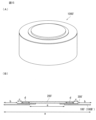
- FIG. 2 is a perspective view schematically showing the appearance of a secondary battery according to an embodiment of the present invention.
- FIG. 3 is a schematic diagram of a secondary battery according to an embodiment of the present invention (FIG. 3(A): sectional view, FIG. 3(B): half-divided perspective view).
- FIG. 4 is a schematic diagram showing typical elements constituting a secondary battery according to an embodiment of the present invention.
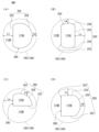
- 5(A) to 5(D) are schematic diagrams each showing a plan view of the main surface of a secondary battery according to an embodiment of the present invention.
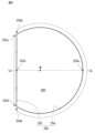
- FIGS. 6(A) to 6(D) are schematic diagrams each showing a planar view outline of an electrode terminal according to an embodiment of the present invention together with a planar view outline of an exterior body.
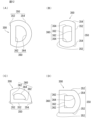
- 7(A) to 7(D) are schematic diagrams each showing a plan view outline of an electrode terminal according to an embodiment of the present invention.
- FIG. 8 is a schematic diagram showing a plan view outline of an electrode terminal according to an embodiment of the present invention.
- 9(A) to 9(D) are schematic diagrams each showing a plan view outline of an exterior body according to an embodiment of the present invention.
- FIG. 10 is a schematic diagram showing a configuration related to the opening of the outer case of a secondary battery according to an embodiment of the present invention.
- FIG. 11 is a schematic diagram for explaining a vent mechanism to which the present invention relates.
- 12(A) to 12(D) are schematic diagrams each showing a plan view outline of an insulating seal member according to an embodiment of the present invention.
- FIG. 13 is a schematic diagram for explaining the deflection or distortion of the exterior body when the cell internal pressure increases abnormally.
- FIGS. 14(A) and 14(B) are schematic perspective views for explaining the "installation mode of the external lead-out member".
- 15(A) and 15(B) are schematic diagrams for explaining a virtual battery that is the base assumed in the [Example].
- FIG. 16(A) is a schematic diagram in which the configurations of the example and comparative example are modeled, respectively, and
- FIG. 16(B) is a schematic diagram showing the non-terminal area area of the modeled configuration so that it can be seen. .
- FIG. 17 is a graph showing the results of the simulation.
- a "cross-sectional view” described directly or indirectly in this specification is based on a hypothetical cross section of the secondary battery cut along the stacking direction of the electrode assembly or electrode constituent layers that constitute the secondary battery. ing.
- the direction of "thickness” described directly or indirectly in this specification is based on the stacking direction of the electrode materials constituting the secondary battery, the direction along the winding axis of the wound laminated structure, and the like.
- the direction of "thickness” may correspond to the plate thickness direction of such a secondary battery.
- a “planar view” may correspond to, for example, a view obtained when the object is viewed along the normal or perpendicular direction of the main surface (for example, the upper surface) of the object.
- up-down direction and left-right direction used directly or indirectly in this specification correspond to the up-down direction and the left-right direction in the drawings, respectively.
- the same reference numerals or symbols indicate the same members or parts or the same meanings.
- the vertically downward direction that is, the direction in which gravity acts
- the opposite direction corresponds to the "upward direction.”
- Secondary battery refers to a battery that can be repeatedly charged and discharged. Therefore, the secondary battery according to the present invention is not excessively limited by its name, and may also include, for example, an electricity storage device.
- the secondary battery according to the present invention includes an electrode assembly in which electrode constituent layers including a positive electrode, a negative electrode, and a separator are laminated.
- An electrode assembly 10 is illustrated in FIGS. 1(A) and 1(B). As shown in the figure, a positive electrode 1 and a negative electrode 2 are stacked with a separator 3 in between to form an electrode constituent layer 5, and an electrode assembly 10 is constructed by stacking at least one such electrode constituent layer 5. ing.
- the electrode constituent layer 5 has a planar layered structure in which it is not wound but is stacked in a planar manner.
- FIG. 1(B) the electrode constituent layer 5 has a wound laminated structure wound in a spiral shape. That is, in FIG.
- the electrode constituent layer 5 including the positive electrode 1, the negative electrode 2, and the separator 3 disposed between the positive electrode 1 and the negative electrode 2 has a wound structure in which it is wound in a roll shape.
- an electrode assembly is enclosed in an outer case together with an electrolyte (for example, a non-aqueous electrolyte).
- an electrolyte for example, a non-aqueous electrolyte.
- the structure of the electrode assembly is not necessarily limited to a flat layered structure or a wound structure.
- the electrode assembly may have a so-called stack-and-fold structure in which a positive electrode, a separator, and a negative electrode are stacked on a long film and then folded.
- the positive electrode is composed of at least a positive electrode material layer and a positive electrode current collector.
- a positive electrode material layer is provided on at least one side of the positive electrode current collector.
- the positive electrode material layer contains a positive electrode active material as an electrode active material.
- each of the plurality of positive electrodes in the electrode assembly may have a positive electrode material layer provided on both sides of a positive electrode current collector, or may have a positive electrode material layer provided only on one side of the positive electrode current collector. It may be something that exists.
- the negative electrode is composed of at least a negative electrode material layer and a negative electrode current collector.
- a negative electrode material layer is provided on at least one side of the negative electrode current collector.
- the negative electrode material layer contains a negative electrode active material as an electrode active material.
- the plurality of negative electrodes in the electrode assembly may each have a negative electrode material layer provided on both sides of a negative electrode current collector, or may have a negative electrode material layer provided only on one side of the negative electrode current collector. It may be something that exists.
- the electrode active materials contained in the positive and negative electrodes are substances that are directly involved in the transfer of electrons in secondary batteries, and are the main materials of the positive and negative electrodes that are responsible for charging and discharging, that is, battery reactions. be. More specifically, ions are brought into the electrolyte due to "the positive electrode active material contained in the positive electrode material layer" and "the negative electrode active material contained in the negative electrode material layer", and these ions are brought into contact between the positive electrode and the negative electrode. The battery moves and exchanges electrons to perform charging and discharging.
- the positive electrode material layer and the negative electrode material layer may be layers capable of intercalating and deintercalating lithium ions.
- the secondary battery according to the present invention may be a non-aqueous electrolyte secondary battery in which lithium ions move between the positive electrode and the negative electrode via the non-aqueous electrolyte to charge and discharge the battery.
- the secondary battery according to the present invention corresponds to a so-called “lithium ion battery” and has layers capable of inserting and extracting lithium ions as a positive electrode and a negative electrode.
- the positive electrode active material of the positive electrode material layer is composed of, for example, granules, and a binder may be included in the positive electrode material layer for more sufficient contact between the particles and shape retention. Furthermore, a conductive additive may be included in the positive electrode material layer in order to facilitate the transmission of electrons that promote battery reactions. Similarly, when the negative electrode active material of the negative electrode material layer is composed of, for example, granules, a binder may be included for more sufficient contact between the particles and shape retention, and for the transfer of electrons that promote battery reactions. A conductive additive may be included in the negative electrode material layer to facilitate this. As described above, since a plurality of components are contained, the positive electrode material layer and the negative electrode material layer can also be referred to as a "positive electrode composite material layer" and a "negative electrode composite material layer,” respectively.
- the positive electrode active material may be a material that contributes to intercalation and desorption of lithium ions.
- the positive electrode active material may be, for example, a lithium-containing composite oxide.
- the positive electrode active material may be a lithium transition metal composite oxide containing lithium and at least one transition metal selected from the group consisting of cobalt, nickel, manganese, and iron. That is, in the positive electrode material layer of the secondary battery according to the present invention, such a lithium transition metal composite oxide is preferably contained as a positive electrode active material.
- the positive electrode active material may be lithium cobalt oxide, lithium nickel oxide, lithium manganate, lithium iron phosphate, or a material in which some of the transition metals thereof are replaced with another metal.
- such positive electrode active materials may be contained as a single species, they may be contained in a combination of two or more types.
- the binder that can be contained in the positive electrode material layer is not particularly limited, but includes polyvinylidene fluoride, vinylidene fluoride-hexafluoropropylene copolymer, vinylidene fluoride-tetrafluoroethylene copolymer, and polytetrafluoroethylene. At least one selected from the group consisting of:
- the conductive additive that can be included in the positive electrode material layer is not particularly limited, but includes carbon black such as thermal black, furnace black, channel black, Ketjen black, and acetylene black, graphite, carbon nanotubes, and vapor phase growth. Examples include at least one selected from the group consisting of carbon fibers such as carbon fibers, metal powders such as copper, nickel, aluminum and silver, and polyphenylene derivatives.
- the thickness of the positive electrode material layer is not particularly limited, but may be 1 ⁇ m or more and 300 ⁇ m or less, for example, 5 ⁇ m or more and 200 ⁇ m or less.
- the thickness dimension of the positive electrode material layer is the thickness inside the secondary battery, and the average value of the measured values at arbitrary 10 points may be adopted.
- the negative electrode active material may be a material that contributes to intercalation and desorption of lithium ions. From this point of view, the negative electrode active material may be, for example, various carbon materials, oxides, and/or lithium alloys.
- Examples of various carbon materials for the negative electrode active material include graphite (natural graphite and/or artificial graphite), hard carbon, soft carbon, and/or diamond-like carbon.
- Examples of the oxide of the negative electrode active material include at least one selected from the group consisting of silicon oxide, tin oxide, indium oxide, zinc oxide, lithium oxide, and the like.
- the lithium alloy of the negative electrode active material may be any metal that can be alloyed with lithium, such as Al, Si, Pb, Sn, In, Bi, Ag, Ba, Ca, Hg, Pd, Pt, Te, Zn, It may be a binary, ternary or higher alloy of metal such as La and lithium.
- the binder included in the negative electrode material layer is not particularly limited, but at least one selected from the group consisting of styrene-butadiene rubber, polyacrylic acid, polyvinylidene fluoride, polyimide resin, and polyamideimide resin. can be mentioned.
- the conductive additive that can be included in the negative electrode material layer is not particularly limited, but includes carbon black such as thermal black, furnace black, channel black, Ketjen black and acetylene black, graphite, carbon nanotubes, and vapor phase growth. Examples include at least one selected from the group consisting of carbon fibers such as carbon fibers, metal powders such as copper, nickel, aluminum and silver, and polyphenylene derivatives.
- the negative electrode material layer may contain a component resulting from a thickener component (for example, carboxymethylcellulose) used during battery manufacture.
- the thickness of the negative electrode material layer is not particularly limited, but may be 1 ⁇ m or more and 300 ⁇ m or less, for example, 5 ⁇ m or more and 200 ⁇ m or less.
- the thickness dimension of the negative electrode material layer is the thickness inside the secondary battery, and the average value of the measured values at ten arbitrary points may be adopted.
- the positive electrode current collector and negative electrode current collector used in the positive electrode and negative electrode are members that help collect and supply electrons generated in the electrode active material due to battery reactions.
- Such an electrode current collector may be a sheet-like metal member. Further, the electrode current collector may have a porous or perforated form.
- the current collector may be metal foil, punched metal, mesh, expanded metal, or the like.
- the positive electrode current collector used in the positive electrode is preferably made of a metal foil containing at least one selected from the group consisting of aluminum, stainless steel, nickel, etc., and may be, for example, an aluminum foil.
- the negative electrode current collector used in the negative electrode is preferably made of a metal foil containing at least one selected from the group consisting of copper, stainless steel, nickel, etc., and may be a copper foil, for example.
- the thickness dimensions of the positive electrode current collector and the negative electrode current collector are not particularly limited, but may be 1 ⁇ m or more and 100 ⁇ m or less, for example, 10 ⁇ m or more and 70 ⁇ m or less.
- the thickness dimension of the positive electrode current collector and the negative electrode current collector is the thickness inside the secondary battery, and the average value of the measured values at ten arbitrary points may be adopted.
- the separator used for the positive and negative electrodes is a member provided mainly from the viewpoint of preventing short circuits due to contact between the positive and negative electrodes and retaining electrolyte.
- the separator can be said to be a member that allows ions to pass through while preventing electronic contact between the positive electrode and the negative electrode.
- a separator is a porous or microporous insulating member that has a membrane shape due to its small thickness.
- a microporous membrane made of polyolefin may be used as the separator.
- the microporous membrane used as the separator may contain, for example, only polyethylene (PE) or polypropylene (PP) as the polyolefin.
- the separator may be a laminate composed of a "microporous membrane made of PE" and a "microporous membrane made of PP.”
- the surface of the separator may be covered with an inorganic particle coating layer and/or an adhesive layer.
- the surface of the separator may have adhesive properties.
- the separator is not particularly limited by its name, and may be a solid electrolyte, a gel electrolyte, and/or insulating inorganic particles having similar functions.
- the thickness of the separator is not particularly limited, but may be 1 ⁇ m or more and 100 ⁇ m or less, for example, 2 ⁇ m or more and 20 ⁇ m or less.
- the thickness dimension of the separator is the thickness inside the secondary battery (particularly the thickness between the positive electrode and the negative electrode), and the average value of the measured values at arbitrary 10 points may be adopted.
- an electrode assembly consisting of electrode constituent layers including a positive electrode, a negative electrode, and a separator may be enclosed in an exterior body together with an electrolyte.
- the electrolyte may be a "non-aqueous" electrolyte that includes an organic electrolyte and an organic solvent, or it may be an "aqueous” electrolyte that includes water.
- the secondary battery preferably includes a "non-aqueous" electrolyte. That is, it is preferable that the electrolyte is a non-aqueous electrolyte. In the electrolyte there will be metal ions released from the electrodes (positive and/or negative), and therefore the electrolyte can assist in the movement of metal ions in battery reactions.
- the electrolyte may have a liquid or gel form.
- a non-aqueous electrolyte is an electrolyte containing a solvent and a solute.
- the solvent may be an organic solvent.
- a specific organic solvent for the non-aqueous electrolyte may contain at least carbonate.
- Such carbonates may be cyclic carbonates and/or linear carbonates.
- examples of the cyclic carbonates include at least one selected from the group consisting of propylene carbonate (PC), ethylene carbonate (EC), butylene carbonate (BC), and vinylene carbonate (VC). be able to.
- Examples of chain carbonates include at least one selected from the group consisting of dimethyl carbonate (DMC), diethyl carbonate (DEC), ethylmethyl carbonate (EMC), and dipropyl carbonate (DPC).
- non-aqueous electrolyte a combination of cyclic carbonates and chain carbonates may be used as the non-aqueous electrolyte, for example a mixture of ethylene carbonate and diethyl carbonate may be used.
- Li salt such as LiPF 6 and/or LiBF 4 may be used as a specific solute of the non-aqueous electrolyte.
- the exterior body of a secondary battery is a member that encloses an electrode assembly in which electrode constituent layers including a positive electrode, a negative electrode, and a separator are laminated.
- the exterior body may be a metal exterior body having a non-laminated structure.
- the secondary battery of the present invention is characterized at least in the configuration related to the opening of the exterior body that encloses the electrode assembly.
- the electrode terminal provided so as to cover the opening of the exterior body and the battery tearing mechanism associated therewith.
- the electrode terminal (positive electrode terminal or negative electrode terminal) arranged on the exterior body using the insulating seal member is electrically connected to the electrode assembly via the conductive member.
- the insulating seal member is interposed between the electrode terminal and the exterior body, and is provided around the opening of the exterior body through which the conductive member passes.
- the electrode terminal and the exterior body are bonded to each other by an insulating seal member provided around the opening of the exterior body. It can be said that the electrode terminal is preferably bonded to the insulating seal member, and the exterior body is also preferably bonded to the insulating seal member.
- the electrode terminal when the exterior body is provided with an opening through which the conductive member passes, the electrode terminal is placed on the exterior body surface corresponding to the area around the opening (on the outer surface of the exterior body) through the opening. It is provided using the adhesive force of the insulating seal member so as to cover it.
- the electrode terminal is provided on the exterior body solely by the adhesive force of the insulating sealing member, without relying on mechanical or structural effects such as caulking (to put it simply, the electrode terminal and/or the exterior body are preferably (The electrode terminal is attached to the exterior body without being crimped.)
- the electrode terminals associated with the battery cleavage mechanism have never been seen before.
- the outline of the electrode terminal in plan view has a unique shape different from that of the conventional one.
- the planar view contour of the electrode terminal is composed of both straight portions and curved portions.
- the plan view outline of the electrode terminal on the surface in contact with the insulating seal member is composed of both a straight portion and a curved portion.
- the outline of the exterior body in plan view at the surface that contacts the insulating seal member includes a curve.
- the curved portion of the electrode terminal and a portion of the curve of the exterior body are opposed to each other.
- FIG. 2 shows an external appearance of a secondary battery 1000 according to an embodiment of the present invention
- FIGS. 3(A) and 3(B) show a cross-sectional view of a secondary battery 1000 according to an embodiment of the present invention. and shown in half-split perspective.
- FIG. 4 separately shows elements related to the characteristics of the secondary battery of the present invention.
- FIGS. 5A to 5D show a plan view of the top side of the secondary battery (the side where the electrode terminals are installed), and particularly show the plan view contours of the electrode terminals and the exterior body.
- FIGS. 6A to 6D show contours of the electrode terminals in plan view corresponding to FIGS. 5A to 5D, respectively.
- 5(A) and 6(A) show the plan view contours corresponding to FIGS. 2 to 4
- FIGS. 5(B) to (D) and 6(B) to (D) show the other 3 shows a plan view outline of a secondary battery according to a preferred embodiment of the present invention.
- the planar view outline 250 of the electrode terminal 200 viewed from the outside of the secondary battery has a unique shape with a straight portion. 252 and a curved portion 254.
- the planar contour of the electrode terminal on the surface in contact with the insulating seal member consists of both straight parts and curved parts (below, the outer contour of the electrode terminal on the surface in contact with the insulating seal member) (Also, the outer edge contour is also referred to as the "planar view contour of the electrode terminal" or simply the "contour of the electrode terminal").
- a plan view outline 160 of the exterior body 100 viewed from the outside of the main surface of the secondary battery is preferably curved. That is, in the exterior body 100, the plan view contour 160 (particularly the outer edge contour forming the outer edge of the battery) of the surface in contact with the insulating seal member 300 includes curvature.
- the plan view outline 160 of the exterior body 100 on the surface that is in direct contact with the insulating seal member 300 used for installing the electrode terminal 200 includes a curve (hereinafter, such a exterior body is generally referred to as the outer side).
- the outer contour or outer edge contour of the exterior body when viewed from above is also referred to as the "planar view contour of the exterior body" or simply the “outline of the exterior body”).
- the outline 160 of the exterior body 100 in plan view is curved as a whole; for example, the outline of the exterior body in plan view is entirely curved.
- the plan view outline 160 of the exterior body 100 may be, for example, circular.
- the curved outline of the exterior body faces the curved portion of the electrode terminal, and preferably faces directly.
- the curved portion 254 in the plan view contour 250 of the electrode terminal 200 and the curved portion 160a in the plan view contour 160 of the exterior body 100 are opposed to each other. (preferably directly facing each other).
- the curved portion in the outline of the electrode terminal 200 and a part of the curve in the outline of the exterior body 100 are facing or facing each other.
- facing each other means a positional relationship in which the curved portion of the electrode terminal and the curve of the exterior body are adjacent to or lined up with each other in the planar view outline of the secondary battery (for example, when the secondary battery is It means that they have a positional relationship in which they are adjacent to each other or lined up while being separated from each other in a plan view of the battery when viewed from the outside, and preferably they are adjacent or lined up more proximally or more directly. It means having a matching positional relationship.
- the electrode terminal corresponds to an output terminal for external connection.
- an electrode terminal is provided on the main surface of the exterior body so as to cover an opening provided there, and preferably the electrode terminal is provided through an insulating seal member provided around the opening. Glued or pasted.
- the electrode terminal 200 has, for example, a flat plate shape (see FIGS. 3 and 4).
- the electrode terminal 200 may be a flat member (for example, the electrode terminal 200 may have a planar main surface facing each other).
- the flat electrode terminal may be, for example, a metal disk. Since the electrode terminal has a flat plate shape, the thickness of the electrode terminal may be substantially constant.
- the electrode terminal is electrically connected to the conductive member of the electrode assembly.
- the conductive member may be a member containing metal (for example, simply a metal member), and preferably may be a metal member having an elongated shape.
- the electrically conductive member may consist of an electrode current collector of the electrode assembly, or may be a current collection lead provided on the electrode assembly (particularly the electrode thereof).
- the conductive member may be made of an electrode current collector, the conductive member may be made of a metal portion of the electrode current collector where no electrode material is provided.
- the conductive member is a current collection lead, the conductive member may be made of a metal member having a thin wall shape and/or an elongated shape.
- the conductive member that electrically connects the electrode assembly and the electrode terminal to each other can also be referred to as a "tab.”
- the conductive member preferably has flexibility, and may be provided in a bent and/or bent form to contribute to the cleavage mechanism described below.
- the closed region formed by the plan view outline 250 of the electrode terminal may also be single, for example, as shown in FIGS. 6(A) to 6(D).
- the closed area formed by the plan view outline of the exterior body particularly the plan view outline 160 of the exterior body forming the outer edge of the exterior body.
- a single closed region of the planar view outline 250 of the electrode terminal is formed.
- the material of the electrode terminal 200 is not particularly limited as long as it has electrical conductivity.
- the electrode terminal may be made of a metal material that is generally used as a terminal material for secondary batteries.
- the electrode terminal may include at least one metal selected from the group consisting of iron, SUS, aluminum, nickel, and copper.
- the planar view outline of the electrode terminal refers to the outline of the electrode terminal when viewed in plan (for example, when the electrode terminal is viewed along the normal direction or perpendicular direction to the main surface of the electrode terminal). This refers to the outline of the terminal shape obtained when Preferably, among the surfaces constituting the electrode terminal, the outer edge contour of the surface directly in contact with the insulating seal member used for installing the electrode terminal (for example, the electrode terminal surface that is on the same plane as the contacting surface) is defined as “electrode”. It can be regarded as "the outline of the terminal in plan view”. To put it simply, the "planar view contour of the electrode terminal” may correspond to the contour shape formed by the outer edge (preferably the outermost edge) of the electrode terminal.
- the "planar view contour of the exterior body” refers to the contour of the exterior body when viewed in plan as above, and typically the outer edge contour or outer contour of the exterior body. It refers to that.
- the contour, outer contour, or outer edge of the surface of the exterior that is in direct contact with the insulating seal member on which the electrode terminal is installed e.g., the surface of the exterior that is on the same plane as the contacting surface
- the contour preferably a contour that can be located outside the contour of the electrode terminal when viewed in plan, or an outer contour or an outer edge contour
- the "planar view contour of the exterior body” in the present invention refers to the shape of the exterior body when the secondary battery is viewed from a direction perpendicular to the main surface of the electrode terminal. (For example, it may be regarded as the outline of the exterior body located outside the electrode terminal, or the outer contour or the outermost contour of the exterior body.)
- the outline of the electrode terminal in plan view is composed of both a straight part and a curved part, but in such a structure, the area other than the electrode terminal on one main surface of the battery is This makes it easier to serve as a suitable area.
- the proportion of the planar view area of the non-terminal region 110B on the main surface of the battery is set to It is possible to secure a better or larger amount compared to the above.
- the degree of freedom in designing the battery is increased. For example, it becomes easier to provide an external lead-out member for external connection to the non-terminal region 110B, and the secondary battery of the present invention can be more easily used as a suitable battery (for example, a circuit provided outside the battery can be easily provided). It may also become possible to design a compact battery such as providing it on the main surface of the secondary battery of the present application). Such a problem becomes apparent when the outline of the exterior body in plan view at the surface where the exterior body contacts the insulating seal member includes a curve, and the curved portion of the electrode terminal and a part of the curve of the exterior body face each other. easy to become
- both the terminal region and the non-terminal region are easily provided on the main surface of the battery, while the electrode terminal is It becomes easier to appropriately secure the relevant sealing area. In other words, it becomes easier to secure a more suitable proportion of the planar view area of the non-terminal region 110B on the main surface of the battery without unfavorably impairing sealing strength and/or long life.
- the planar view contour of the electrode terminal is composed of both a straight part and a curved part, so that the area of the sealing area to which the electrode terminal is related via the insulating seal member on the exterior body (hereinafter, It becomes easy to suitably provide a terminal region and a non-terminal region on the main surface of the battery while ensuring a suitable seal area (also referred to as a "seal area"). This also tends to become apparent when the plan view contour of the exterior body at the surface where the exterior body contacts the insulating seal member includes a curve, and the curved portion of the electrode terminal and a part of the curve of the exterior body face each other. .
- the feature of the contour of the electrode terminal in plan view which is composed of both straight portions and curved portions, also contributes favorably to a safety mechanism when the internal pressure of the cell increases, that is, to a battery rupture mechanism.
- the electrode terminals cleave outward in order to prevent an unintentional battery explosion. ” is relatively easy to occur.
- the electrode terminal is likely to cleave open from the straight line portion of the planar contour of the electrode terminal (this cleavage will be described later), and the possibility of predicting an abnormal rise in cell internal pressure is increased.
- the secondary battery of the present invention can be provided as a safer battery while avoiding as much as possible unpredictability regarding the rupture mode when the cell internal pressure increases excessively.
- Such an effect is also apparent when the planar view contour of the exterior body at the surface where the exterior body contacts the insulating seal member includes a curve, and the curved portion of the electrode terminal and a part of the curve of the exterior body are opposed to each other. easy to become
- the curved portion of the electrode terminal is opposite to the curve of the exterior body, but in a preferred embodiment, the straight portion of the electrode terminal is also opposite to the curve of the exterior body (the curved portion of the electrode terminal is opposite to the curve of the exterior body). (a curved part that is different from the curved part).
- the curved portion 254 of the planar profile 250 of the electrode terminal 200 and the curved portion 160a of the planar profile 160 of the exterior body 100 are opposed to each other. Such a facing relationship between the electrode terminal and the exterior body may also be formed with respect to the linear contour portion of the electrode terminal.
- the curve in the planar view contour 160 of the exterior body 100 may have a portion opposite to the curved portion 254 of the planar view contour 250 of the electrode terminal 200, and may also have a portion opposite to the straight portion 252.
- the planar view outline 160 of the exterior body 100 is curved as a whole, and the curved portion 254 of the electrode terminal 200 faces the exterior body 100.
- the curved part of the electrode terminal and the curved part of the exterior body face each other, but the curved part of the electrode terminal in plan view is different from the outer contour of the exterior body in plan view. (the non-curved contour portion). It can be said that it is preferable that the curved part of the planar profile of the electrode terminal is positioned relatively closer to the curve of the planar profile of the outer package than the straight part of the planar profile of the electrode terminal. For example, in plan view shown in FIGS.
- the shortest separation distance Lw between the curved portion 254 of the plan view contour 250 of the electrode terminal 200 and the plan view external contour 160 of the exterior body 100 is smaller than Ls. It can also be said that the straight portion of the planar contour of the electrode terminal is positioned further distal to the curved portion relative to the planar outer contour of the exterior body. In the case of an electrode terminal having such a contour in plan view, the terminal region and the non-terminal region are more easily provided on the main surface of the battery, making it easier to provide a desired secondary battery.
- shortest separation distance Lw refers to the smallest or shortest distance in a direction perpendicular to the tangent of the curved portion in plan view.
- shortest separation distance Ls refers to the smallest or shortest distance in the direction perpendicular to the straight line portion.
- one end portion of the straight portion and the curved portion are arranged so that the straight portion and the curved portion are continuous in the plan view contour of the electrode terminal (for example, so as to continuously form the plan view contour).
- One end portion of the portion is shared with each other.
- the planar contour of the electrode terminal is formed by a contour in which a straight portion and a curved portion are connected through their end portions.
- one end portion 252a of the straight portion 252 and one end portion 252a of the curved portion 254 are The end portions 254a may be overlapped so as to be shared with each other, whereby the planar view contour 250 may be configured such that the straight portion 252 and the curved portion 254 are connected to each other.
- a terminal region and a non-terminal region are more easily secured on the main surface of the battery, making it easier to provide a desired secondary battery. For example, it becomes easier to provide an external lead-out member for external connection in the non-terminal region.
- a terminal area and a non-terminal area are easily provided on the main surface of the battery while ensuring a suitable sealing area.
- the curved portion may be arcuate. That is, the planar view contour of the electrode terminal may include a shape corresponding to a part of a circle.
- the plan view outline 250 of the electrode terminal may be composed of a circular arc outline 254' as the curved part 254 and a straight part 252 combined with the arc outline 254'.
- the planar view contour of the electrode terminal including such an arcuate curved part it becomes easier to secure a terminal area and a non-terminal area on the main surface of the battery, preferably while ensuring a suitable sealing area.
- the terminal area and the non-terminal area are easily secured on the main surface of the battery, making it easier to obtain a desired secondary battery. This may become more obvious when the secondary battery is button-shaped or coin-shaped. For example, it becomes easier to provide an external lead-out member for external connection in a non-terminal region, contributing to a more suitable battery design.
- the planar view contour of the electrode terminal may include an arcuate curved portion corresponding to the circumference of at least a semicircle, 1/4 circle, 1/6 circle, or 1/8 circle. .
- the curved portion has an arc shape and the contour of the exterior body in plan view (especially the outer contour of the exterior body in plan view forming the outer edge of the exterior body) has a circular shape
- the virtual circle constituting the arc of the curved portion and the contour of the exterior body in plan view are circular.
- the circles of the plan view contour may form concentric circles with each other.
- the arcuate contour of the electrode terminal and the circular contour of the exterior body may share the same circular center when viewed from above. This makes it easier to ensure a more uniform and larger sealing area between the electrode terminal and the exterior body, which in turn improves the sealing area associated with the electrode terminal (simply put, the bonding of the electrode terminal in the area around the opening of the exterior body).
- concentric circles in this specification does not necessarily mean having a perfect concentric circle relationship, but also approximately concentric circles that can be considered to have a substantially concentric circle relationship as recognized by a person skilled in the art, even though they have changed from that. (For example, the center of the circle is shifted by a distance of within 30%, within 20%, within 10%, within 5%, or within 3% with respect to the circular diameter of the planar outline of the exterior body. ).
- the proportion of the curved portion in the planar profile of the electrode terminal is relatively larger than the proportion of the straight portion. That is, in the plan view profile of the electrode terminal, the total length of the curved portion may be relatively longer than the total length of the straight portion. In the mode shown in FIG. 8, when the length of the straight portion 252 is L a and the length of the curved portion 254 is L b , then La ⁇ L b may be satisfied. In the case of an electrode terminal having a plan view profile in which the ratio of curved parts is larger than the ratio of straight parts, it becomes easier to secure a terminal area and a non-terminal area on the main surface of the battery, and a desired battery can be obtained. It's easy to get caught.
- the length L b of the curved portion may be 1.2 times or more, for example, 1.5 times or more, the length L a of the straight portion.
- the upper limit of the length L b of the curved portion is not particularly limited, but may be three times or twice the length L a of the straight portion.
- the planar contour of the electrode terminal is 1.2L a ⁇ L b ⁇ 3L a , 1.2L a ⁇ L b ⁇ 2.5L a , 1.2L a ⁇ L b ⁇ 2L a , 1.5L a ⁇ L b ⁇ 3L a , 1.5L a ⁇ L b ⁇ 2.5L a , or 1.5L a ⁇ L b ⁇ 2L a .
- the planar contour of the electrode terminal is composed of only straight portions and curved portions.
- the planar contour of the electrode terminal may be composed of only a combination of "straight lines” and "curves".
- the features of the present disclosure are likely to stand out, and the effects of the present invention are likely to become apparent.
- the terminal region and the non-terminal region can be more easily secured on the main surface of the battery, and the effect that, for example, it is easier to provide the external lead-out member for external connection to the non-terminal region can be more apparent.
- the effect of properly providing a well-balanced terminal area and non-terminal area on the main surface of the battery while ensuring a suitable sealing area related to the electrode terminal can be made more apparent.
- the electrode terminal is provided to the exterior body.
- An electrode terminal may be provided in a region including at least a part of the main surface (preferably a part of the planar main surface) of the exterior body. In particular, it is designed to cover at least an opening in the exterior body (also referred to herein as an "exterior body opening") through which a conductive member electrically connected to the electrode terminal (i.e., a conductive member extending from the electrode assembly) passes.
- the electrode terminal is provided to the exterior body.
- the electrode terminal is preferably provided to the exterior body so as to cover all of the opening of the exterior body, and the electrode terminal is preferably provided so as to cover the planar exterior body surface around the opening of the exterior body. provided.
- the sheath refers to a member for housing or enveloping an electrode assembly in which electrode constituent layers including a positive electrode, a negative electrode, and a separator are laminated.
- the sheath may be a metal sheath having a non-laminated configuration.
- the exterior body is not a laminate member consisting of a metal sheet/fusion layer/protective layer.
- the exterior body in the present invention may be different from the exterior body of a soft case type battery, which corresponds to a pouch made of a so-called laminate film.
- a metal sheath having a non-laminated construction preferably has a construction consisting of a single piece of metal.
- such a metal sheath may be a single member made of metal such as iron, stainless steel (SUS), and/or aluminum.
- the term "single metal member” here means that the exterior body does not have a so-called laminate structure, and in a narrow sense, the exterior body is a member that consists essentially only of metal. It means that. Therefore, as long as the member is made essentially only of metal, the surface of the metal sheath may be subjected to an appropriate surface treatment. For example, in a cut surface obtained by cutting such a metal exterior body in its thickness direction, a single metal layer can be observed except for areas where surface treatment has been performed.
- stainless steel in this specification refers to, for example, stainless steel defined in “JIS G 0203 Steel Terminology”, and may be chromium or an alloy steel containing chromium and nickel.
- the exterior body may have a can shape (in such a case, the exterior body can be said to have an “exterior can”).
- the exterior body may be mainly composed of two parts.
- the exterior body may be composed of two parts: a first metal exterior body and a second metal exterior body, which are metal members.
- each of the first metal exterior body and the second metal exterior body may be a single metal member.
- the exterior body may have a relatively thin thickness.
- each of the first metal exterior body and the second metal exterior body may have a thickness dimension of 50 ⁇ m or more and less than 200 ⁇ m, for example, 50 ⁇ m or more and 190 ⁇ m or less, 50 ⁇ m or more and 180 ⁇ m or less, or 50 ⁇ m or more and 170 ⁇ m or less. It may be.
- the above-mentioned "exterior body opening” may be provided in one of the first metal exterior body and the second metal exterior body.
- an opening may be provided in either the first metal exterior body or the second metal exterior body, and the electrode terminal may be provided with respect to one of the sub-exterior bodies having the opening.
- the first metal sheath and the second metal sheath of the metal member may be combined with each other by laser welding to form a sheath, or may be combined with each other by caulking to form a sheath.
- One of the first metal exterior body and the second metal exterior body may be a cup-shaped member, and the other of the first metal exterior body and the second metal exterior body may be a lid-shaped member.
- the metal exterior bodies may be joined together by welding or caulking the peripheral portion of the lid-like member from the outside, which may enable relatively simple encapsulation.
- a "cup-shaped member” has a side wall or side part corresponding to a body part and a main surface part (typically, for example, a bottom part) that is continuous with the side wall or side part, and has a hollow part formed inside. It means a member.
- the term "lid-like member” refers to a member that is assembled to cover the cup-like member (preferably, a member that is combined to cover the cup-like member (preferably, a member that is in contact with the side wall of the cup-like member to shut off the inner hollow part of the cup-like member from the outside).
- a member installed in the The lid-like member is, for example, a single member (typically a flat member) that extends in a plane direction (particularly in a direction perpendicular to the direction in which the side wall of the cup-like member extends in an upright manner). In particular, it may be a member provided so as to be in contact with the side wall of the cup-shaped member.
- the lid-like member may be provided in the lid-like member. That is, the exterior body is composed of the cup-shaped member 100A and the lid-shaped member 100B, and the lid-shaped member 100B instead of the cup-shaped member 100A may have the exterior body opening 150 (see FIG. 4).
- the lid-like member includes an exterior body opening, an electrode terminal is provided to the lid-like member.
- the secondary battery can be manufactured by once obtaining an assembly in which the electrode terminal is provided on the lid-like member, and the secondary battery can be obtained relatively easily.
- the "exterior body opening" may be provided in the cup-shaped member.
- the exterior body is composed of a cup-shaped member and a lid-shaped member, and the cup-shaped member rather than the lid-shaped member may have an exterior body opening (for example, the exterior body may be formed on a surface corresponding to the bottom of the cup-shaped member). (may have a body opening).
- an electrode terminal may be provided to the cup-shaped member (for example, to a surface corresponding to the bottom of the cup-shaped member).
- the cup-shaped member and the lid-shaped member may be hermetically sealed with each other by bonding. That is, the cup-shaped member and the lid-shaped member are not caulked, and therefore, there is no need for airtight sealing by caulking.
- the secondary battery is more space-saving than the secondary battery equipped with an exterior body that is caulked.
- the non-crimped form of the cup-shaped member and the lid-shaped member suitably contributes to miniaturization of the secondary battery and improvement in energy density.
- the exterior body opening may also have the same contour shape as the electrode terminal.
- it is a secondary battery that includes a conductive member that electrically connects an electrode assembly and an electrode terminal, and an insulating seal member is installed around the opening of an exterior body through which the conductive member passes through the electrode.
- the outer contour of the opening of the exterior body in plan view may be composed of both a straight portion and a curved portion.
- the exterior body opening 150 has two contours 180: a straight portion 182 and a curved portion 184. It consists of In other words, the shape of the opening edge forming the exterior body opening 150 is composed of a straight portion and a curved contour. In a preferred aspect, the contour 180 of the exterior body opening 150 is composed of only two types, a straight portion 182 and a curved portion 184, and therefore, the shape of the opening edge forming the exterior body opening 150 has a straight portion and a curved portion. It consists only of walls.
- a secondary battery having an exterior opening with such a contour in plan view can provide more suitable sealing.
- the plan view contour of the exterior body opening and the plan view contour of the electrode terminal tend to have a similar shape to each other, and the sealing of the electrode terminal in the peripheral area of the exterior body opening tends to be more uniform.
- the width of the seal area formed around the opening of the exterior body tends to be constant around the opening). In other words, a safer battery is likely to be produced in terms of stable hermetic sealing.
- an insulating seal member is provided between the electrode terminal and the exterior body.
- FIG. 10 shows the mutual arrangement relationship of the exterior body 100, the electrode terminal 200, and the insulating seal member 300 in a cross-sectional view.
- an insulating seal member 300 is interposed between the exterior body 100 and the electrode terminal 200.
- the exterior body 100 has an exterior body opening 150 as an opening, and an insulating seal member 300 is arranged on the exterior body surface 158 around the exterior body opening 150.
- the electrode terminal 200 is joined to the exterior body 100 in the area surrounding the exterior body opening 150 due to the bondability of the insulation seal member 300 via the insulation seal member. As shown in FIG.
- the electrode terminal 200 is preferably attached on an insulating seal member 300 so as to close the exterior body opening 150 from the outside.
- an insulating seal member 300 is interposed between the electrode terminal 200 and the exterior body surface 158 around the opening 150 of the exterior body through which the conductive member 400 passes. .
- the insulating seal member 300 is sandwiched between the electrode terminal 200 and the exterior body 100 in the joint area between the electrode terminal 200 and the exterior body 100.
- the insulating seal member 300 may be provided along the periphery of the opening 150 on the surface of the exterior body (preferably on the outer surface of the exterior body). In order to provide more suitable insulation, the insulating seal member 300 may be provided so as to extend to an area outside the electrode terminal 200. That is, as shown in FIG. 10, for example, the insulating seal member 300 may be provided on the exterior body 100 so as to protrude outward from the electrode terminal 200. Similarly, in order to provide more suitable insulation, the insulating seal member 300 may be provided further inside the outer casing 100 beyond the edge of the opening 150. That is, as shown in FIG. 10, for example, the insulating seal member 300 may extend further inward so as to exceed the edge portion 155 forming the opening 150 in the exterior body 100. A portion of 300 may extend to the area of opening 150.
- the term "insulating seal member” refers to at least a member that is interposed between the exterior body and the electrode terminal and contributes to insulation between them, and is used to seal the battery (more specifically, between the exterior body and the electrode terminal). This means a member that also contributes to airtight sealing between terminals. There is no particular restriction on the material type of the insulating seal member as long as it exhibits insulating properties. "Insulation” as used herein refers to the insulation properties of general insulators, and hence may have the electrical resistivity of general insulators, and is merely an example, but is at least 1.0.
- the insulating seal member may have a resistivity (at room temperature of 20° C.) of ⁇ 10 5 ⁇ m or more, preferably 1.0 ⁇ 10 6 ⁇ m or more, more preferably 1.0 ⁇ 10 7 ⁇ m or more.
- the insulating seal member has not only insulation properties but also fusion properties. This is because it becomes easier to improve sealing performance.
- the insulating seal member may include a thermoplastic resin.
- the insulating seal member may comprise a polyolefin such as polyethylene and/or polypropylene.
- the insulating sealing member as an insulating bonding material may contain an adhesive component exhibiting insulating properties, since it can be expected that the sealing performance will be improved.
- adhesives examples include acrylic adhesives such as acrylic acid ester copolymers, rubber adhesives such as natural rubber, silicone adhesives such as silicone rubber, and urethane resins.
- acrylic adhesives such as acrylic acid ester copolymers
- rubber adhesives such as natural rubber
- silicone adhesives such as silicone rubber
- urethane resins Urethane adhesives such as ⁇ -olefin adhesives, ether adhesives, ethylene-vinyl acetate resin adhesives, epoxy resin adhesives, vinyl chloride resin adhesives, chloroprene rubber adhesives, cyanoacrylate adhesives, etc.
- Adhesives water-based polymer-isocyanate adhesives, styrene-butadiene rubber adhesives, nitrile rubber adhesives, nitrocellulose adhesives, reactive hot melt adhesives, phenolic resin adhesives, modified silicone adhesives agent, polyamide resin adhesive, polyimide adhesive, polyurethane resin adhesive, polyolefin resin adhesive, polyvinyl acetate resin adhesive, polystyrene resin solvent adhesive, polyvinyl alcohol adhesive, polyvinylpyrrolidone resin adhesive Examples of adhesives include polyvinyl butyral resin adhesives, polybenzimidazole adhesives, polymethacrylate resin adhesives, melamine resin adhesives, urea resin adhesives, and/or resorcinol adhesives. can.
- a secondary battery in which an insulating seal member is interposed between the electrode terminal and the surface of the exterior body is likely to be provided as a safer battery.
- the electrode terminal opens (preferably, the electrode terminal moves toward the outside of the battery) to prevent a more serious accident such as an unintentional battery explosion. cleavage) can result.
- this is to prevent the battery from exploding due to an increase in the pressure inside the outer casing (also referred to as "cell internal pressure" in this specification) due to gas generated by abnormal heat generation inside the battery due to overcharging or internal short circuit, etc.
- the secondary battery is provided with a vent mechanism that releases internal gas when the cell internal pressure rises excessively.
- the secondary battery of the present invention is preferably able to be displaced so that the electrode terminal can release the sealed state blocking the opening of the exterior body when the cell internal pressure increases excessively.
- the electrode terminals are displaced to open so as to be peeled off from the insulating seal member on the surface of the exterior body (see Figure 11), and as a result, the opening of the exterior body communicates with the outside. This allows internal gas to escape to the outside and prevents battery explosions.
- the insulating seal member may also have the same contour shape as the electrode terminal. That is, the planar view profile of the insulating seal member may be composed of both a straight portion and a curved portion.
- 12(A) to 12(D) show plan view outlines of the insulating seal member 300 corresponding to FIGS. 5(A) to 6(D) or 6(A) to 6(D), respectively.
- the outer contour 350 of the insulating seal member 300 is composed of two types: a straight portion 352 and a curved portion 354.
- the outline of the outer edge of the insulating seal member 300 in plan view is composed of a straight outline and a curved outline.
- the outer contour of the insulating seal member 300 is composed of only two types, a straight portion and a curved portion, and therefore, the outer edge of the insulating seal member 300 has only a straight contour and a curved contour in a plan view. It consists of The inner contour of the insulating seal member 300 may also be similar.
- the inner contour 360 of the insulating seal member 300 is composed of two types: a straight portion 362 and a curved portion 364.
- the planar contour of the inner edge of the insulating seal member 300 is composed of a straight contour and a curved contour.
- the inner contour of the insulating seal member 300 is composed of only two types, a straight portion and a curved portion, and therefore, the inner edge of the insulating seal member 300 has only a straight contour and a curved contour in a plan view. It consists of
- the planar view outline of the outer edge and/or inner edge of the insulating seal member and the planar view outline of the electrode terminal tend to have a similar shape to each other, so that the insulating seal member and the electrode terminal are attached to the exterior body. This contributes to more uniform sealing of the area surrounding the opening (preferably, the width dimension of the sealing area formed around the opening of the exterior body tends to be constant around the opening). In other words, a safer battery is likely to be produced in terms of stable hermetic sealing.
- the shapes themselves are similar to the outline shape 250 of the electrode terminal shown in FIGS. 6(A) to 6(D), respectively. It has a relation of shape. Therefore, the various features described above regarding the plan view profile 250 of the electrode terminal may similarly apply to the plan view profile 350, 360 of the insulating seal member.
- the distance between the curved portion 254 of the contour 250 of the electrode terminal 200 in plan view and the external contour 160 of the exterior body 100 in plan view is constant. This is especially true when the curved portion 250 of the electrode terminal 200 has an arc shape and the outline of the exterior body in plan view (particularly the outer outline of the exterior body in plan view forming the outer edge of the exterior body) has a circular shape ( (See Figures 6(A) to (D)).
- the "shortest separation distance Lw" explained using FIGS. 6(A) to 6(D) may be a constant distance in plan view.
- Such a constant separation distance will contribute to a more uniform seal.
- the width of the sealing area formed around the opening of the exterior body tends to be constant around the opening, and more stable hermetic sealing can be easily achieved.
- the electrode terminal in the present invention is a non-crimped metal plate. Moreover, since such metal plates are not caulked, for example, the metal plates extend on the same plane when viewed in cross section. To put it simply, the electrode terminal serving as the external output terminal does not have a bent shape as a whole, but has a flat shape. For example, as shown in FIGS. 3A and 10, the electrode terminal 200 may have a rectangular cross-sectional shape. Such an electrode terminal 200 has not undergone a history of deformation under pressure, and is likely to have longer-term stability from the viewpoint of the material. In other words, it can easily become an external output terminal suitable for long-term use of a secondary battery.
- the insulating seal member 300 may also extend on the same plane, for example, in a cross-sectional view. That is, the cross-sectional shape of the insulating seal member provided adjacent to the electrode terminal may not be bent, but may be, for example, rectangular. As shown in FIG. 3(A) and FIG. 10, the thickness of the insulating seal member 300 may be substantially constant.
- Such an insulating seal member 300 can be said to be an insulating member or an insulating material in which the effect of pressure deformation upon installation of an electrode terminal is further reduced.
- the insulating seal member 300 may have a film form.
- the insulating seal member 300 may be provided using a film-like insulating member precursor having a shape close to the final shape.
- the cleavage mechanism related to the electrode terminal that is, the vent mechanism will be explained in detail.
- the force that the electrode terminal 200 receives due to the cell internal pressure also increases.
- the force that the electrode terminal 200 receives is the bonding force between the electrode terminal 200 and the exterior body 100 (that is, the force applied to the exterior body of the electrode terminal 200 via the insulating seal member 300). (adhesive force or fixing force to the body 100), and at least a portion of the electrode terminal 200 can be detached from the exterior body 100.
- the electrode terminal 200 is provided so as to cover the opening 150 of the exterior body 100, but the electrode terminal 200 can be displaced so that the cover opens (see FIG. 11). Due to such displacement of the electrode terminal 200, excess gas inside the exterior body is released to the outside of the exterior body, and more serious accidents such as unintentional battery explosion can be prevented.
- cell internal pressure means, in a broad sense, the pressure inside the outer casing of a secondary battery. In a narrow sense, “cell internal pressure” means the pressure inside the hermetically sealed exterior body that includes the electrode assembly (particularly the internal pressure when the battery is in use).
- the "insulating seal member” in this embodiment contributes to the vent mechanism as described above, and can be referred to as an insulating seal that can be peeled off when the cell internal pressure is abnormal, that is, a peelable member.
- the secondary battery of the present invention can be used as a battery with high predictability in the event of an abnormal increase in cell internal pressure, since the planar view contour of the electrode terminal is composed of both straight portions and curved portions. Specifically, when the internal pressure of the cell rises abnormally, the electrode terminal tends to cleave starting at a point corresponding to the "straight line" of the planar contour of the electrode terminal, which increases predictability. , a more suitable battery design becomes possible.
- the substantially planar main surface of the exterior body is structurally more flexible than the side surfaces of the exterior body, which may be provided as curved or folded surfaces.
- the central part in the width direction of the main surface of the battery tends to have a larger curvature or bend than the outer part, and the main surface of the exterior body (in the illustrated embodiment, the lid The shaped member 100B) can be deformed as shown in FIG. 13, for example. Due to such deformation of the exterior body (i.e., deformation of the battery), in locations where the curvature is relatively large (hereinafter also referred to as "maximum curvature locations"), there is a "straight line" of the plan view outline of the electrode terminal. Corresponding points are preferably located.
- the straight portion 252 of the planar view contour of the electrode terminal 200 is positioned relatively closer to the curved portion 254 at the maximum curvature point U (see FIG. 13). Therefore, the straight portion of the contour of the electrode terminal in plan view is relatively more susceptible to the deformation stress of the exterior body than the curved portion, and cleavage such as peeling off of the electrode terminal from the straight portion of the contour of the electrode terminal in plan view may occur. It's easy to get carried away.
- the secondary battery of the present invention can be obtained by enclosing an electrode assembly in which electrode constituent layers including a positive electrode, a negative electrode, and a separator are laminated in an exterior body.
- the electrode assembly may be manufactured by a conventional method, and a secondary battery can be obtained by arranging it inside the outer case.
- the exterior body is provided with an insulating seal member as a sealing material in a region surrounding the exterior body opening, and an electrode terminal is provided through the insulating seal member so that the exterior body opening is closed.
- the step of placing the electrode assembly inside the cup-shaped member and closing the open end of the cup-shaped member with the lid-shaped member (For example, the lid-shaped member and the cup-shaped member may be combined with each other through a welding process or the like), and an insulating seal member is provided in the area surrounding the exterior body opening of the exterior body, so that the exterior body opening is covered.
- a secondary battery can be obtained through the process of providing electrode terminals on the exterior body through the insulating seal member.
- the electrode terminal itself whose contour in plan view is composed of both straight portions and curved portions, can be obtained by a conventional metal processing method.
- the type of metal processing method itself is not particularly limited.
- the electrode terminal is obtained through machining (such as cutting and/or grinding), plastic working (such as pressing and/or forging), and/or casting (sand casting and/or skeleton casting). be able to.
- a metal 3D printer may be used to manufacture the electrode terminals.
- the present invention can be embodied in various aspects. This will be explained below.
- This embodiment is characterized by the number of contour components of the planar view contour of the electrode terminal.
- the planar contour of the electrode terminal is composed of a single straight portion and a single curved portion. That is, in the planar view contour of the electrode terminal, each of the two types of contour constituent elements is provided as a single piece.
- only one straight portion 252 and only one curved portion 254 are provided.
- one end portion 252a of the straight portion 252 and one end portion 254a of the curved portion 254 are arranged so that the straight portion 252 and the curved portion 254 are continuous in the plan view contour 250 of the electrode terminal 200.
- the other end portion 252b of the straight portion 252 and the other end portion 254b of the curved portion 254 be shared with each other.
- the center point of the straight portion and the center point of the curved portion may face each other so as to straddle the center of the battery.
- a center point 252c that divides the straight portion 252 into halves and a center point 254c that divides the curved portion 254 in half face each other with the battery center M in between.
- the planar view contour 250 may be configured to surround the battery center M and form a closed area from a single curved part 254 and a single straight part 252.
- battery center M here refers to the center on the main surface of the secondary battery in a broad sense, and in a narrow sense refers to the center of the shape of the outer contour of the exterior body in plan view. (For example, if the external contour of the exterior body in plan view is circular, the center of the circle corresponds to the "battery center M").
- the outline of the electrode terminal in plan view is composed of a single straight part and a single curved part, it becomes easier to appropriately secure the terminal area and the non-terminal area on the main surface of the battery, making it possible to obtain the desired battery. It becomes easier to get caught.
- an external lead-out member for external connection that is, a member provided separately from the electrode terminal for external output
- both the terminal region and the non-terminal region can be easily secured on the main surface of the battery while suitably securing the sealing area.
- the plan view contour of the electrode terminal may have a "bow shape”, "D shape", and/or "half moon shape".
- an arc-shaped, D-shaped and/or half-moon shaped electrode terminal may be provided on the main surface of the battery so as to extend to the above-mentioned "battery center M".
- the electrode terminal including both a straight contour in a plan view and a curved contour in a plan view extends from the center of the battery so as to be biased toward one side of the battery. It's okay to stay.
- the contour of the electrode terminal a contour that includes both a straight contour in plan view and a curved contour in plan view, it becomes easier to secure a desired large sealing area while moving the electrode terminal to one side from the center. It becomes easier to ensure a desired large exposed area of the exterior body (particularly the area of the non-terminal region on the main surface of the exterior body where the electrode terminals are provided) without impairing strength and/or long life.
- both one external lead-out member and the other external lead-out member for external connection are provided on the same battery main surface.
- the same battery main surface may correspond to a battery surface composed of an electrode terminal and an exterior body.
- both one external lead-out member and the other external lead-out member are provided on the main surface of the battery. .
- FIG. 14(A) and 14(B) show an embodiment in which a pair of external lead-out members 500A and 500B are provided on a terminal-installed battery surface 600 that includes a terminal area 110A and a non-terminal area 110B. has been done.
- a positive electrode side external lead-out member 500A for connection to the outside such as an external circuit and/or external device
- a positive electrode side external lead-out member 500A for connection to the outside such as an external circuit and/or external device
- a negative electrode side external lead-out member 500B for connection is provided on the terminal installation battery surface 600.
- the configuration of such a secondary battery is due to the plan view contour of the electrode terminal, which is composed of both a straight portion and a curved portion.
- the planar view contour of the electrode terminal is composed of a straight portion and a curved portion, so that the terminal region 110A and the non-terminal region 110B are more easily provided on the terminal-installed battery surface.
- a plan view contour is such that the non-terminal region 110B is a larger area (particularly a larger area compared to the case where the plan view contour of the electrode terminal does not have both a straight part and a curved part).
- the non-terminal region 110B can be provided as a region where it is easy to provide an external lead-out member for external connection. Therefore, preferably both the one external lead-out member and the other external lead-out member can be suitably provided on the terminal-installed battery surface.
- the secondary battery according to this aspect has the external lead-out members suitably concentrated on one battery main surface, and is a battery that is more suitable in terms of external connections.
- one of them may be provided on the electrode terminal, and the other may be provided on the non-terminal area. That is, one external lead-out member may be provided for the electrode terminal, and the other external lead-out member may be provided for the non-terminal region of the main surface of the battery that is a region other than the electrode terminal. Thereby, the terminal-installed battery surface can be utilized more effectively while maintaining the desired conductive function of the two external lead-out portions.
- one and the other of the external lead-out members may be provided side by side (preferably side by side so as to be adjacent to each other) on the main surface of the battery.
- the external lead-out member on the positive electrode side is at least partially disposed on the electrode terminal to be electrically connected to the electrode terminal, and the external lead-out member on the negative electrode side is electrically connected to the non-terminal area. At least a portion of the non-terminal region may be disposed on the non-terminal region to be connected to the non-terminal region. Or vice versa, the external lead-out member on the negative electrode side is at least partially disposed on the electrode terminal to be electrically connected to the electrode terminal, and the external lead-out member on the positive electrode side is disposed on the non-terminal. At least a portion of the non-terminal region may be disposed on the non-terminal region to be electrically connected to the non-terminal region.
- the pair of external lead-out members 500A and 500B may have the same form or shape. Alternatively, the pair of external lead-out members 500A and 500B may have mutually different forms or shapes. For example, as shown in FIG. 14(B), the external lead-out members 500A and 500B may each have an elongated shape.
- the material of the external lead-out member is not particularly limited as long as it has electrical conductivity.
- the material of the external lead-out members 500A and 500B may be a metal material commonly used for electrical connection of batteries.
- the external lead-out members 500A and 500B may each include at least one metal selected from the group consisting of iron, SUS, aluminum, nickel, and copper.
- the external lead-out member is a member that is provided to suitably connect the battery to the outside (for example, an element that requires energy of the battery of the present disclosure, such as an external circuit and/or an external device). It can also be referred to as an "external output tab" or "conductive member for external connection.” Therefore, in the secondary battery of the present disclosure, an external lead-out member, which is an external output tab, can be suitably attached to the same surface of the secondary battery, and as a result, a compact battery design including an external circuit is possible.
- the secondary battery of the present disclosure may include an external circuit above the terminal-installed battery surface, and two external lead-out members provided on the terminal-installed battery surface are provided between the external circuit and the terminal-installed battery surface. may be electrically connected by.
- both one and the other of the external lead-out members are positioned between the terminal-installed battery surface and the external circuit.
- the external circuit which is preferably arranged above the battery surface where the terminal is installed, is at least due to the external lead-out members on the positive electrode side and negative electrode side provided on the same battery main surface (upper end main surface). Contributes to the realization of the pack.
- the size of the external circuit arranged above the terminal-installed battery surface in plan view is the same as or smaller than the terminal-installed battery surface.
- the secondary battery 1000 has a button-shaped or coin-shaped external shape (for example, see FIG. 2).
- the circular shape of the secondary battery in plan view means that the shape of the electrode assembly and/or the exterior body containing it can be circular when the electrode assembly is viewed from above or below. .
- circular here is not limited to a complete circle (i.e., simply a “circle” or a “perfect circle”), but may be normally included in a "round shape” as recognized by those skilled in the art, even though it may be modified. It also includes a substantially circular shape. For example, it may not only be a circle or a perfect circle, but also the curvature of its arc may be locally different, and it may also be a shape derived from a circle or a perfect circle, such as an ellipse. As a typical example, a battery having such a circular shape in plan view corresponds to a so-called button-shaped or coin-shaped battery. In one preferred embodiment, the secondary battery of the present invention is a cylindrical battery.
- the curvature in the plan view outline of the exterior body is an arc shape, and has a portion opposite to the curved part of the plan view outline of the electrode terminal, and also has a portion opposite to the curved part of the plan view outline of the electrode terminal. It may also have a portion that opposes the straight line portion of the viewing contour.
- the curvature in the plan view outline of the exterior body is an arc shape, and has a portion opposite to the curved part of the plan view outline of the electrode terminal, and also has a portion opposite to the curved part of the plan view outline of the electrode terminal. It may also have a portion that opposes the straight line portion of the viewing contour.
- there is another case whose contour is different from "the arc portion 160a of the case 100 that the curved part 254 of the electrode terminal 200 is facing".
- the arc portion 160b may face the straight portion 252 of the electrode terminal 200.
- the plan view outline of the opening of the exterior body may be composed of both a straight portion and a curved portion.
- the shape of the opening contour of such an exterior body opening in plan view is similar to the plan view contour of the electrode terminal, and preferably has a similar shape having a smaller area than the plan view contour of the electrode terminal. It has become.
- the outer contour of the outer casing in plan view (that is, the outline of the portion forming the outer edge) is circular
- the outer contour of the electrode terminal in plan view, the opening contour of the outer casing opening in plan view, and the insulating seal member are non-circular, and preferably, they may be composed of both straight portions and curved portions.
- the dimension of the secondary battery in the axial direction is smaller than the width dimension (diameter dimension).
- the secondary battery of the present invention is not limited to this, and the dimension in the axial direction (for example, the normal direction of the main surface of the battery) of the secondary battery is the same as the width dimension (diameter dimension), or is larger than the width dimension (diameter dimension). It may be.
- the entire secondary battery is relatively small.
- the secondary battery may be a small battery.
- the width dimension of the secondary battery or the exterior body may be on the order of millimeters.
- the width dimension of the secondary battery or the exterior body (if the width dimension is not constant, the maximum dimension thereof) may be approximately 5 mm or more and 50 mm or less, for example, 5 mm or more and 40 mm or less, 5 mm or more and 30 mm or less, or It may be 5 mm or more and 20 mm or less.
- the lower limit value is not limited to 5 mm, but may be 10 mm (excluding 10 mm).
- the width dimension of the above-mentioned secondary battery or exterior body may be about greater than 10 mm and less than 50 mm, for example, greater than 10 mm and less than 40 mm, greater than 10 mm and less than 30 mm, greater than 10 mm and less than 20 mm, and greater than 10 mm and less than 18 mm. etc.
- the width dimension of the secondary battery may correspond to the diameter dimension of the exterior body (for example, its lid member).
- the secondary battery according to this aspect although it is small in size, it is easier to secure a terminal region and a non-terminal region on the main surface of the battery.
- an external lead-out member for external connection can be suitably provided in the non-terminal region.
- such a small battery may have a single battery main surface provided with both a positive electrode side external lead-out member and a negative electrode side external lead-out member.
- the cleavage mechanism that is, the vent mechanism was mentioned, but in the vent mechanism, the conductive member connected to the electrode terminal may have "play" so that the electrode terminal opens more suitably. That is, if there is not enough length of the conductive member connected to the electrode terminal, the existence of the conductive member itself may become a resistance to opening of the electrode terminal. Therefore, the length of the conductive member between the electrode assembly and the electrode terminal may be relatively long to the extent that it does not undesirably inhibit the opening of the electrode terminal (in particular, the length of the conductive member may be longer than the length of the conventional conductive member). ).
- the conductive member may have a length that does not create excessive tension between the electrode terminal and the electrode assembly that would prevent the electrode terminal from opening.
- a conductive member extending from the electrode assembly may be connected to the electrode terminal with its deflection and/or bending.
- the electrode terminal when comparing the electrode terminal and the exterior body, the electrode terminal may have higher rigidity. In other words, at least a portion of the exterior body may have lower rigidity than the electrode terminal. For example, the exterior portion having the surface on which the electrode terminal is arranged may have lower rigidity than the electrode terminal. In other words, the electrode terminal may have relatively higher rigidity than the exterior portion having the surface on which it is arranged. Such a difference in rigidity contributes to realizing a more suitable vent mechanism.
- the electrode terminal In the event of an abnormality such as an excessively high cell internal pressure, the electrode terminal is difficult to deform due to its high rigidity, but the exterior part that makes up the surface on which the electrode terminal is placed can deform, so it is difficult to join the insulating seal member. The surface becomes easy to peel off, and the electrode terminal becomes easy to open.
- the thickness of the exterior part that forms the surface on which the electrode terminal is arranged is It may be 170 ⁇ m or less.
- the thickness of such an exterior portion is 170 ⁇ m or less, the exterior body will easily deform in the event of an abnormality such as an excessively high cell internal pressure, and the electrode terminal will tend to open as a vent mechanism.
- the thickness of the exterior portion is greater than 170 ⁇ m (for example, 200 ⁇ m or more), the exterior body is less likely to deform in the event of an abnormality, and the electrode terminal 200 is less likely to open as intended.
- the lower limit of the thickness of such a thin exterior portion is not particularly limited, but may be, for example, 50 ⁇ m or more and 170 ⁇ m or less. Note that when the opening 150 is provided in the lid-like member 100B of the exterior body 100 shown in FIG. It's fine.
- lid-like member 100B alone constitutes "an exterior part that provides a surface on which electrode terminals are arranged," it is easy to provide as a thin member, and therefore, it is likely to be a member that easily deforms such as bending or distortion. .
- the exterior body may be composed of cup-shaped members. That is, the first metal exterior body and the second metal exterior body may each be a cup-shaped member.
- the exterior body may be composed of at least a first metal exterior body that is a cup-shaped member and a second metal exterior body that is also a cup-shaped member.
- the first metal exterior body and the second metal exterior body of the cup-shaped member may be combined so that their side walls are aligned with each other to form the exterior body.
- the cup-shaped member of either the first metal sheath or the second metal sheath may be provided with the above-mentioned "sheath opening", so that the electrode terminal and the insulating seal member can be connected to the cup-shaped member. May be provided. Furthermore, although it has been mentioned that when the exterior body is composed of a cup-shaped member and a lid-like member, the exterior body opening is provided in the lid-like member, the present invention is not necessarily limited thereto. An exterior opening may be provided in the cup-shaped member.
- the present invention is not necessarily limited to this.
- the insulating seal member may be provided so as not to protrude outward from the electrode terminal but to be hidden under the electrode terminal.
- the insulating seal member may be provided only at approximately the same level as or inside the outer edge of the electrode terminal.
- the end portion of the straight portion and the end portion of the curved portion are shared with each other.
- the shape of the shared portion between the straight portion and the curved portion is particularly There are no restrictions.
- the shape in plan view of the portion shared by the straight portion and the curved portion may be rounded or angular.
- non-terminal area has been mentioned above, it may particularly refer to an area as mentioned in [Example] described later.
- the area R on the side that does not include the electrode terminal 200 is specifically defined as a "non-terminal area". (See the right side of FIG. 16(B)). If there are a plurality of straight contours, the summation region of the regions similarly formed for each straight contour (the summation region including any one of the mutually overlapping portions) may be regarded as the non-terminal region.
- the "planar view contour of the electrode terminal on the surface where the electrode terminal contacts the insulating sealing member” may be simply regarded as the "outer contour of the electrode terminal when the secondary battery is viewed from the outside.” good.
- the planar view contour of the exterior body at the surface where the exterior body contacts the insulating sealing member is simply defined as "when the secondary battery is viewed from the outside (particularly from the outside of the battery surface where the electrode terminals are installed)" It may be regarded as the "outer contour of the exterior body”.
- the outline of the lid-like member in plan view may be regarded as "the contour in plan view of the exterior body on the surface where the exterior body contacts the insulating seal member.” If the lid-like member has a form in which its outer edge is bent toward the outside of the battery, as shown in FIGS. 3(A) and 3(B) and FIG.
- the contour in plan view formed by the portion excluding the bent outer edge can be regarded as "the contour in plan view of the exterior body on the surface where the exterior body contacts the insulating sealing member" (although this is just an example, For example, the contour indicated by reference numeral 160' may be considered such an intended contour).
- the plan view outline of the lid-like member formed by the entire member including the bent outer edge i.e., the outline of the lid-like member as a whole including the outer edge when viewed from the outside
- the contour in plan view may be regarded as "the contour in plan view of the exterior body on the surface where the exterior body contacts the insulating seal member.”
- the lid-shaped member and the cup-shaped member are airtightly combined with each other, so that the outer edge contour of the lid-shaped member and the outer edge contour of the cup-shaped member have the same shape (for example, substantially the same shape) in plan view. or a similar shape), the outer edge contour of the cup-shaped member in plan view may be regarded as "the plan view contour of the exterior body on the surface where the exterior body contacts the insulating seal member.”
- Electrode assembly an exterior body housing the electrode assembly; and an electrode terminal disposed on the exterior body and electrically connected to the electrode assembly via a conductive member,
- An insulating seal member (or an insulating member) interposed between the electrode terminal and the exterior body and provided around an opening in the exterior body through which the conductive member passes allows the electrode terminal and the exterior body to be connected to each other.
- a plan view outline of the electrode terminal on a surface where the electrode terminal contacts the insulating seal member is composed of both a straight portion and a curved portion, and a plan view of the exterior body on the surface where the exterior body contacts the insulating seal member.
- a secondary battery wherein the outline includes a curve, and the curved portion of the electrode terminal and a portion of the curve of the exterior body face each other.
- One end portion of the straight portion and one end portion of the curved portion are shared with each other so that the straight portion and the curved portion are continuous in the plan view contour of the electrode terminal.
- ⁇ 4> The secondary battery according to any one of ⁇ 1> to ⁇ 3>, wherein a proportion of the curved part in the planar view contour of the electrode terminal is relatively larger than a proportion of the straight part.
- ⁇ 5> The secondary battery according to any one of ⁇ 1> to ⁇ 4>, wherein the curved portion is arcuate in the plan view contour of the electrode terminal.
- ⁇ 6> According to any one of ⁇ 1> to ⁇ 5>, wherein the curved part is positioned relatively closer to the curve of the exterior body than the straight part of the electrode terminal.
- secondary battery. ⁇ 7> It has two external lead-out members for external connection, one and the other of the external lead-out members are provided on the same battery main surface, and the same battery main surface is connected to the The secondary battery according to any one of ⁇ 1> to ⁇ 6>, which corresponds to a battery surface composed of an electrode terminal and the exterior body.
- the one of the external lead-out members is provided with respect to the electrode terminal, and the other of the external lead-out members is provided with respect to a non-terminal area that is a region other than the electrode terminal on the same battery main surface.
- the secondary battery according to ⁇ 7> which is provided.
- ⁇ 9> The secondary battery according to any one of ⁇ 1> to ⁇ 8>, wherein the planar view contour of the electrode terminal is constituted by the single straight portion and the single curved portion. .
- ⁇ 10> The secondary battery according to any one of ⁇ 1> to ⁇ 9>, wherein a plan view opening contour of the opening of the exterior body is composed of both a straight portion and a curved portion.
- ⁇ 11> The secondary battery according to any one of ⁇ 1> to ⁇ 10>, wherein the insulating seal member has a contour in plan view composed of both a straight portion and a curved portion.
- the electrode assembly includes a positive electrode and a negative electrode capable of intercalating and deintercalating lithium ions.
- a model study was conducted in connection with the present invention. Specifically, a simulation was performed regarding the area of the non-terminal region on the main surface of the battery.
- FIGS. 15(A) and 15(B) An assumed base virtual battery 1000' is shown in FIGS. 15(A) and 15(B). The following items were set as prerequisites for such a virtual battery.
- the battery has an overall cylindrical shape. Electrode terminals are attached to the top side of the cylindrical battery via an insulating seal member.
- the lid member is joined to the can member at its outer periphery by laser welding.
- the outer diameter (a) of the lid member is 12 mm.
- the distance (b) between the outer diameter of the lid member and the insulating seal member should be 1 mm or more so that the insulation seal member is not affected by heat when laser welding the outer periphery of the lid member.
- FIG. 16A shows a schematic diagram in which the configurations of the example and the comparative example are modeled.
- the can member is omitted, and the lid member is also shown as a simple flat plate.
- non-terminal area area the effective area of the non-terminal area (hereinafter also simply referred to as "non-terminal area area”) that can be practically used for installing the external lead-out member in the lid member is compared between the example and the comparative example.
- a schematic diagram is shown in FIG. 16(B).
- FIG. 16(B) it was found that the non-terminal region area R can be made larger in the example, and a wider area for connection of the external lead-out member can be secured.
- FIG. 17 shows a graph regarding the change in the area of the non-terminal region when the dimension a (outer diameter of the lid member) in the preconditions is changed. As shown in the graph of FIG. 17, it can be seen that under the above precondition, when the dimension a is larger than ⁇ 10 mm, it can become substantially significant in terms of the area of the non-terminal region, and the larger the dimension a becomes, the more significant it becomes. Ta.
- the secondary battery according to the present invention can be used in various fields where battery use or power storage is expected. Although this is just an example, the secondary battery of the present invention can be used in the electrical, information, and communication fields where electrical and electronic devices are used (e.g., mobile phones, smartphones, notebook computers, digital cameras, activity meters, arm computers, etc.).
- electrical and electronic devices e.g., mobile phones, smartphones, notebook computers, digital cameras, activity meters, arm computers, etc.
- household and small industrial applications e.g., power tools, golf carts, household/nursing care/industrial robots), large industrial applications (e.g., forklifts, elevators, harbor cranes), transportation systems (e.g., hybrid vehicles, electric vehicles, buses, trains, electric assist) Bicycles, electric motorcycles, etc.), power system applications (e.g., various power generation, road conditioners, smart grids, home-installed power storage systems, etc.), medical applications (medical equipment such as earphones and hearing aids), and pharmaceutical applications. (in the field of medication management systems, etc.), as well as in the IoT field, and space/deep sea applications (for example, in the fields of space probes, underwater research vessels, etc.).
- household and small industrial applications e.g., power tools, golf carts, household/nursing care/industrial robots
- large industrial applications e.g., forklifts, elevators, harbor cranes
- transportation systems e.g., hybrid vehicles, electric vehicles, buses, trains
- Patent Document 1 the diameter of the electrode terminal is large, and the exposed area of the exterior member on the battery surface where the electrode terminal is provided is small. Therefore, it is not normally assumed that a member for external output (for example, a tab) is connected to the exterior member surface of the battery surface. Further, in the structure of Patent Document 2, since two circular electrode terminals are attached to the same surface of the battery, the terminals themselves are each small, and a large sealing area of the insulating seal member cannot be secured for each terminal.
- Patent Document 2 can ensure the initial battery's airtight sealing, because the two terminals are individually smaller, the amount of electrolyte volatilized from inside the cell and the amount outside the cell It is thought that the amount of water intrusion from the battery can become large, making it impossible to ensure the long-term reliability of the battery, and in addition, the adhesive strength of the electrode terminal cannot be increased.
- Electrode assembly 100 Exterior body 100A Cup-shaped member 100B Lid-like member 110A Terminal area 110B Non-terminal area 150 Exterior body opening 155 Exterior body opening edge 158 Exterior body surface 160 Planar view outline of exterior body/ Outer contour of the exterior body (outer contour of the secondary battery) 160' Planar view contour of the exterior body/outer contour of the exterior body (outer contour of the secondary battery) 160a A curved portion of the outer contour of the exterior body that faces the curved contour portion of the electrode terminal in plan view 160b A curved portion of the outer contour of the exterior body that faces the straight contour portion of the electrode terminal in plan view 180 Outline of the exterior body opening 182 Exterior body opening 184 Curved outline of the opening of the exterior body 200 Electrode terminal 250 Planar view outline of the electrode terminal 252 Straight part 252a One end of the straight part 252b The other end of the straight part 252c Half-division point of the straight part 254 Curved portion 254' Arc profile 254a One
Landscapes
- Chemical & Material Sciences (AREA)
- Chemical Kinetics & Catalysis (AREA)
- Electrochemistry (AREA)
- General Chemical & Material Sciences (AREA)
- Engineering & Computer Science (AREA)
- Manufacturing & Machinery (AREA)
- Materials Engineering (AREA)
- Sealing Battery Cases Or Jackets (AREA)
Priority Applications (2)
| Application Number | Priority Date | Filing Date | Title |
|---|---|---|---|
| JP2024544018A JPWO2024048109A1 (https=) | 2022-08-29 | 2023-07-20 | |
| US18/937,396 US20250062507A1 (en) | 2022-08-29 | 2024-11-05 | Secondary battery |
Applications Claiming Priority (2)
| Application Number | Priority Date | Filing Date | Title |
|---|---|---|---|
| JP2022135934 | 2022-08-29 | ||
| JP2022-135934 | 2022-08-29 |
Related Child Applications (1)
| Application Number | Title | Priority Date | Filing Date |
|---|---|---|---|
| US18/937,396 Continuation US20250062507A1 (en) | 2022-08-29 | 2024-11-05 | Secondary battery |
Publications (1)
| Publication Number | Publication Date |
|---|---|
| WO2024048109A1 true WO2024048109A1 (ja) | 2024-03-07 |
Family
ID=90099552
Family Applications (1)
| Application Number | Title | Priority Date | Filing Date |
|---|---|---|---|
| PCT/JP2023/026519 Ceased WO2024048109A1 (ja) | 2022-08-29 | 2023-07-20 | 二次電池 |
Country Status (3)
| Country | Link |
|---|---|
| US (1) | US20250062507A1 (https=) |
| JP (1) | JPWO2024048109A1 (https=) |
| WO (1) | WO2024048109A1 (https=) |
Families Citing this family (1)
| Publication number | Priority date | Publication date | Assignee | Title |
|---|---|---|---|---|
| US12597630B2 (en) * | 2023-08-21 | 2026-04-07 | Meta Platforms Technologies, Llc | Batteries with non-rectangular shapes for augmented reality devices, and systems and methods of use thereof |
Citations (4)
| Publication number | Priority date | Publication date | Assignee | Title |
|---|---|---|---|---|
| CN101847755A (zh) * | 2010-05-27 | 2010-09-29 | 厦门太和动力电源科技有限公司 | 一种异形高倍率聚合物锂离子电池 |
| JP2021158042A (ja) * | 2020-03-27 | 2021-10-07 | マクセルホールディングス株式会社 | 端子付き電池及びその製造方法 |
| JP2021170470A (ja) * | 2020-04-15 | 2021-10-28 | マクセルホールディングス株式会社 | 端子付き電池及びその製造方法 |
| JP2022049674A (ja) * | 2020-09-16 | 2022-03-29 | ヴァルタ マイクロバッテリー ゲゼルシャフト ミット ベシュレンクテル ハフツング | 接触ラグを有する電気化学セル |
-
2023
- 2023-07-20 JP JP2024544018A patent/JPWO2024048109A1/ja active Pending
- 2023-07-20 WO PCT/JP2023/026519 patent/WO2024048109A1/ja not_active Ceased
-
2024
- 2024-11-05 US US18/937,396 patent/US20250062507A1/en active Pending
Patent Citations (4)
| Publication number | Priority date | Publication date | Assignee | Title |
|---|---|---|---|---|
| CN101847755A (zh) * | 2010-05-27 | 2010-09-29 | 厦门太和动力电源科技有限公司 | 一种异形高倍率聚合物锂离子电池 |
| JP2021158042A (ja) * | 2020-03-27 | 2021-10-07 | マクセルホールディングス株式会社 | 端子付き電池及びその製造方法 |
| JP2021170470A (ja) * | 2020-04-15 | 2021-10-28 | マクセルホールディングス株式会社 | 端子付き電池及びその製造方法 |
| JP2022049674A (ja) * | 2020-09-16 | 2022-03-29 | ヴァルタ マイクロバッテリー ゲゼルシャフト ミット ベシュレンクテル ハフツング | 接触ラグを有する電気化学セル |
Also Published As
| Publication number | Publication date |
|---|---|
| JPWO2024048109A1 (https=) | 2024-03-07 |
| US20250062507A1 (en) | 2025-02-20 |
Similar Documents
| Publication | Publication Date | Title |
|---|---|---|
| EP2884563B1 (en) | Electrode lead and secondary battery having same | |
| JP7338701B2 (ja) | 二次電池 | |
| JP7414129B2 (ja) | 二次電池 | |
| EP4152460A1 (en) | Secondary battery and manufacturing method thereof | |
| CN114982028A (zh) | 二次电池及其制造方法 | |
| WO2020218217A1 (ja) | 二次電池 | |
| WO2020218214A1 (ja) | 二次電池 | |
| US12463302B2 (en) | Secondary battery | |
| EP4145617A1 (en) | Secondary battery | |
| US20230246313A1 (en) | Secondary battery | |
| US20250062507A1 (en) | Secondary battery | |
| CN113767496B (zh) | 二次电池 | |
| WO2021140838A1 (ja) | 二次電池 | |
| JP7647761B2 (ja) | 二次電池およびその製造方法 | |
| WO2021006161A1 (ja) | 二次電池 | |
| JP2024011964A (ja) | 二次電池 | |
| JP7616246B2 (ja) | 二次電池および二次電池の製造方法 | |
| WO2023127726A1 (ja) | 二次電池 | |
| JPWO2018105278A1 (ja) | 二次電池 | |
| JP7468635B2 (ja) | 二次電池 | |
| JP2024002700A (ja) | 二次電池 | |
| WO2024057711A1 (ja) | 二次電池 | |
| JP2024002692A (ja) | 二次電池 | |
| JP2024003631A (ja) | 二次電池 |
Legal Events
| Date | Code | Title | Description |
|---|---|---|---|
| 121 | Ep: the epo has been informed by wipo that ep was designated in this application |
Ref document number: 23859878 Country of ref document: EP Kind code of ref document: A1 |
|
| WWE | Wipo information: entry into national phase |
Ref document number: 2024544018 Country of ref document: JP |
|
| NENP | Non-entry into the national phase |
Ref country code: DE |
|
| 122 | Ep: pct application non-entry in european phase |
Ref document number: 23859878 Country of ref document: EP Kind code of ref document: A1 |