WO2024047987A1 - 舵取機 - Google Patents
舵取機 Download PDFInfo
- Publication number
- WO2024047987A1 WO2024047987A1 PCT/JP2023/020766 JP2023020766W WO2024047987A1 WO 2024047987 A1 WO2024047987 A1 WO 2024047987A1 JP 2023020766 W JP2023020766 W JP 2023020766W WO 2024047987 A1 WO2024047987 A1 WO 2024047987A1
- Authority
- WO
- WIPO (PCT)
- Prior art keywords
- hydraulic
- steering gear
- cylinders
- ram
- attached
- Prior art date
- Legal status (The legal status is an assumption and is not a legal conclusion. Google has not performed a legal analysis and makes no representation as to the accuracy of the status listed.)
- Ceased
Links
Images


Classifications
-
- B—PERFORMING OPERATIONS; TRANSPORTING
- B63—SHIPS OR OTHER WATERBORNE VESSELS; RELATED EQUIPMENT
- B63H—MARINE PROPULSION OR STEERING
- B63H25/00—Steering; Slowing-down otherwise than by use of propulsive elements; Dynamic anchoring, i.e. positioning vessels by means of main or auxiliary propulsive elements
- B63H25/06—Steering by rudders
- B63H25/08—Steering gear
- B63H25/14—Steering gear power assisted; power driven, i.e. using steering engine
- B63H25/26—Steering engines
- B63H25/28—Steering engines of fluid type
- B63H25/30—Steering engines of fluid type hydraulic
-
- F—MECHANICAL ENGINEERING; LIGHTING; HEATING; WEAPONS; BLASTING
- F15—FLUID-PRESSURE ACTUATORS; HYDRAULICS OR PNEUMATICS IN GENERAL
- F15B—SYSTEMS ACTING BY MEANS OF FLUIDS IN GENERAL; FLUID-PRESSURE ACTUATORS, e.g. SERVOMOTORS; DETAILS OF FLUID-PRESSURE SYSTEMS, NOT OTHERWISE PROVIDED FOR
- F15B11/00—Servomotor systems without provision for follow-up action; Circuits therefor
- F15B11/02—Systems essentially incorporating special features for controlling the speed or actuating force of an output member
- F15B11/028—Systems essentially incorporating special features for controlling the speed or actuating force of an output member for controlling the actuating force
-
- F—MECHANICAL ENGINEERING; LIGHTING; HEATING; WEAPONS; BLASTING
- F15—FLUID-PRESSURE ACTUATORS; HYDRAULICS OR PNEUMATICS IN GENERAL
- F15B—SYSTEMS ACTING BY MEANS OF FLUIDS IN GENERAL; FLUID-PRESSURE ACTUATORS, e.g. SERVOMOTORS; DETAILS OF FLUID-PRESSURE SYSTEMS, NOT OTHERWISE PROVIDED FOR
- F15B11/00—Servomotor systems without provision for follow-up action; Circuits therefor
- F15B11/08—Servomotor systems without provision for follow-up action; Circuits therefor with only one servomotor
-
- F—MECHANICAL ENGINEERING; LIGHTING; HEATING; WEAPONS; BLASTING
- F15—FLUID-PRESSURE ACTUATORS; HYDRAULICS OR PNEUMATICS IN GENERAL
- F15B—SYSTEMS ACTING BY MEANS OF FLUIDS IN GENERAL; FLUID-PRESSURE ACTUATORS, e.g. SERVOMOTORS; DETAILS OF FLUID-PRESSURE SYSTEMS, NOT OTHERWISE PROVIDED FOR
- F15B11/00—Servomotor systems without provision for follow-up action; Circuits therefor
- F15B11/16—Servomotor systems without provision for follow-up action; Circuits therefor with two or more servomotors
- F15B11/17—Servomotor systems without provision for follow-up action; Circuits therefor with two or more servomotors using two or more pumps
Definitions
- the present disclosure relates to a steering gear.
- Patent Document 1 discloses a steering gear 100 as shown in FIG.
- the steering gear 100 includes a steering gear main body 110 and a control device 120.
- the steering gear main body 110 includes a rudder handle 111 fixed to the rudder shaft 200, a ram 112 that engages with the rudder handle 111, and two cylinders 113 into which both ends of the ram 112 are inserted.
- the steering gear main body 110 includes a hydraulic unit 114 that constitutes a hydraulic circuit together with a cylinder 113.
- the hydraulic unit 114 includes an electromagnetic switching valve as a hydraulic device that operates in response to an electric signal, and this electromagnetic switching valve is controlled by the control device 120.
- the control device 120 is connected to the operating device 130.
- the control device 120 is disposed at a distance from the steering gear body 110, so the electrical wiring between the steering gear body 110 and the control device 120 is relatively small. becomes longer.
- an object of the present disclosure is to provide a steering gear that can shorten the electrical wiring between the steering gear body and the control device.
- the present disclosure provides a Rapson slide-type steering gear body including at least one hydraulic device that operates in response to an electric signal, and the at least one hydraulic device attached to the steering gear body.
- a steering gear is provided, comprising at least one control device for controlling the steering gear.
- the present disclosure provides a Rapson slide-type steering gear body including at least one hydraulic device that operates in response to an electric signal;
- a steering gear is provided, including at least one control device that controls two hydraulic devices.
- a steering gear is provided in which the electrical wiring between the steering gear body and the control device can be shortened.
- FIG. 3 is a hydraulic circuit diagram of the steering gear.
- FIG. 2 is an enlarged view of the main part of FIG. 1.
- FIG. It is a front view of the said principal part.
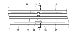
- 6 is a cross-sectional view taken along line VI-VI in FIG. 5.
- FIG. 3 is an enlarged view of the area around the electric motor in FIG. 2.
- FIG. It is a figure which shows another attachment method of a control device.
- 9A and 9B are a front view and a side view, respectively, of the electric motor and surroundings of a steering gear according to a modified example.
- FIG. 2 is a perspective view of a conventional steering gear.
- FIGS. 1 to 3 show a steering gear 1 according to an embodiment.
- the steering gear 1 includes a steering gear main body 11 of the Rapson slide type and at least one control device 9 attached to the steering gear main body 11.
- four control devices 9A to 9D are attached to the steering gear main body 11.
- the steering gear main body 11 includes a rudder handle 2 fixed to the rudder shaft 15 and two hydraulic actuators that swing the rudder handle 2.
- One hydraulic actuator includes a first ram 3A and two first cylinders 4A, 4B, and the other hydraulic actuator includes a second ram 3B and two second cylinders 4C, 4D.
- the steering gear main body 11 may include only one hydraulic actuator.
- the rudder handle 2 includes a cylindrical portion 21 into which the rudder shaft 15 is inserted, and a pair of arm portions 22 that protrude from the side surface of the cylindrical portion 21 in opposite directions.
- Each arm portion 22 includes a pair of opposing walls 23 that face each other in the vertical direction with the corresponding ram (first ram 3A or second ram 3B) in between, and an engagement groove 24 is formed at the tip of these opposing walls 23. It is formed.
- the first ram 3A and the second ram 3B are arranged parallel to each other so as to sandwich the rudder shaft 15 therebetween.
- Pins 31 that protrude upward and downward are provided at the centers of the first ram 3A and the second ram 3B, and these pins 31 engage with the engagement groove 24 of the rudder handle 2 via rollers 32. There is.
- Both ends of the first ram 3A are inserted into the first cylinders 4A and 4B, respectively, and both ends of the second ram 3B are inserted into the second cylinders 4C and 4D, respectively.
- the direction toward the ram of each cylinder will be referred to as the front, and the opposite direction will be referred to as the rear.
- the front parts of the first cylinder 4A and the second cylinder 4C that are adjacent to each other are connected by a connecting plate 13, and the front parts of the first cylinder 4B and the second cylinder 4D that are adjacent to each other are connected to each other by a connecting plate 12.
- the first cylinders 4A, 4B and the second cylinders 4C, 4D are placed on a cylinder installation base 10, which is a part of the hull, and are fixed to the cylinder installation base 10 with bolts and nuts.
- the steering gear main body 11 includes a plurality of hydraulic units 5 that constitute a hydraulic circuit together with the first cylinders 4A, 4B and the second cylinders 4C, 4D.
- the steering gear main body 11 includes four hydraulic units, a first hydraulic unit 5A, a second hydraulic unit 5B, a third hydraulic unit 5C, and a fourth hydraulic unit 5D, and is located above the first cylinders 4A and 4B.
- a first hydraulic unit 5A and a second hydraulic unit 5B are respectively disposed at
- a third hydraulic unit 5C and a fourth hydraulic unit 5D are disposed above the second cylinders 4C and 4D, respectively.
- Each of the first to fourth hydraulic units 5A to 5D includes a tank unit 51, a valve unit 52, and an electric motor 54.
- Tank unit 51 includes a tank that stores hydraulic oil and a hydraulic pump 61 disposed within the tank.
- the electric motor 54 drives a corresponding hydraulic pump 61.
- the tank unit 51 has a substantially rectangular parallelepiped shape.
- the tank unit 51 and the electric motor 54 are attached to corresponding cylinders (one of the first cylinders 4A, 4B or one of the second cylinders 4C, 4D) in a state where they are lined up in the axial direction of the cylinder.
- the tank unit 51 is located near the corresponding ram (first ram 3A or second ram 3B), and the electric motor 54 is located on the opposite side of the ram with the tank unit 51 in between.
- each hydraulic pump 61 is a variable displacement pump, and each of the first to fourth hydraulic units 5A to 5D includes a regulator 53 that changes the displacement of the corresponding hydraulic pump 61. Further, in this embodiment, each hydraulic pump 61 is a double tilting pump, and the discharge direction of the hydraulic pump 61 can be switched by the regulator 53 while the rotation direction remains in one direction. However, the discharge direction of each hydraulic pump 61 may be switched by switching the rotation direction.
- the regulator 53 is a hydraulic device that operates in response to an electrical signal. Incidentally, since the configuration of the regulator 53 is well known, its explanation will be omitted.
- a regulator 53 is attached to one side of the tank unit 51 (in this embodiment, the side facing inward of the steering gear main body 11), and a regulator 53 is attached to the other side of the tank unit 51.
- a valve unit 52 is attached to the side surface (in this embodiment, the side surface facing outside of the steering gear main body 11).
- the hydraulic pump 61 of the second hydraulic unit 5B is connected to the first cylinder 4A by a supply/discharge line 62 and to the first cylinder 4B by a supply/discharge line 63.
- the discharge direction of the hydraulic pump 61 is set to the supply/discharge line 62 side by the regulator 53, the hydraulic oil discharged from the hydraulic pump 61 is supplied to the first cylinder 4A through the supply/discharge line 62, and is also supplied to the first cylinder 4B.
- the hydraulic oil discharged from the hydraulic pump 61 is sucked into the hydraulic pump 61 through the supply/discharge line 63.
- the supply and discharge lines 62 and 63 cross the valve unit 52 of the second hydraulic unit 5B.
- the valve unit 52 includes valves such as relief valves and check valves provided in branch paths branching from the supply/discharge lines 62 and 63.
- the valve unit 52 of the second hydraulic unit 5B is connected to the first cylinder 4A by a hydraulic pipe 1a forming part of a supply/discharge line 62, and is connected to the first cylinder 4A by a hydraulic pipe 1b forming a part of a supply/discharge line 63. It is connected to the first cylinder 4B.
- the hydraulic pump 61 of the first hydraulic unit 5A is connected to the supply/discharge line 62 via a supply/discharge line 64 and to the supply/discharge line 63 via a supply/discharge line 65.
- the discharge direction of the hydraulic pump 61 is set to the supply/discharge line 64 side by the regulator 53, the hydraulic oil discharged from the hydraulic pump 61 is supplied to the first cylinder 4A through the supply/discharge lines 64, 62, and Hydraulic oil discharged from the cylinder 4B is sucked into the hydraulic pump 61 through supply and discharge lines 63 and 65.
- the supply and discharge lines 64 and 65 cross the valve unit 52 of the first hydraulic unit 5A.
- the valve unit 52 includes valves such as relief valves and check valves provided in branch paths branching from the supply/discharge lines 64 and 65.
- the valve unit 52 of the first hydraulic unit 5A is connected to the valve unit 52 of the second hydraulic unit 5B through a hydraulic pipe 1g forming part of the supply/discharge line 64 and a hydraulic pipe 1h forming part of the supply/discharge line 65. has been done.
- the hydraulic pump 61 of the fourth hydraulic unit 5D is connected to the second cylinder 4D by a supply/discharge line 66 and to the second cylinder 4C by a supply/discharge line 67.
- the discharge direction of the hydraulic pump 61 is set to the supply/discharge line 66 side by the regulator 53, the hydraulic oil discharged from the hydraulic pump 61 is supplied to the second cylinder 4D through the supply/discharge line 66, and also to the second cylinder 4C.
- the hydraulic oil discharged from the hydraulic pump 61 is sucked into the hydraulic pump 61 through the supply/discharge line 67.
- the hydraulic oil discharged from the hydraulic pump 61 is supplied to the second cylinder 4C through the supply/discharge line 67, and is also supplied to the second cylinder 4D.
- the hydraulic oil discharged from the hydraulic pump 61 is sucked into the hydraulic pump 61 through the supply/discharge line 66.
- the supply and discharge lines 66 and 67 cross the valve unit 52 of the fourth hydraulic unit 5D.
- the valve unit 52 includes valves such as relief valves and check valves provided in branch paths branching from the supply/discharge lines 66 and 67.
- the valve unit 52 of the fourth hydraulic unit 5D is connected to the second cylinder 4D by a hydraulic pipe 1d forming part of a supply/discharge line 66, and is connected to the second cylinder 4D by a hydraulic pipe 1c forming a part of a supply/discharge line 67. It is connected to the second cylinder 4C.
- the hydraulic pump 61 of the third hydraulic unit 5C is connected to the supply/discharge line 66 via a supply/discharge line 68 and to the supply/discharge line 67 via a supply/discharge line 69.
- the discharge direction of the hydraulic pump 61 is set to the supply/discharge line 68 side by the regulator 53, the hydraulic fluid discharged from the hydraulic pump 61 is supplied to the second cylinder 4D through the supply/discharge lines 68, 66, and Hydraulic oil discharged from the cylinder 4C is sucked into the hydraulic pump 61 through supply and discharge lines 67 and 69.
- the supply and discharge lines 68 and 69 cross the valve unit 52 of the third hydraulic unit 5C.
- the valve unit 52 includes valves such as relief valves and check valves provided in branch paths branching from the supply/discharge lines 68 and 69.
- the valve unit 52 of the third hydraulic unit 5C is connected to the valve unit 52 of the fourth hydraulic unit 5D through a hydraulic pipe 1i forming part of the supply/discharge line 68 and a hydraulic pipe 1j forming part of the supply/discharge line 69. has been done.
- the supply/discharge line 62 and the supply/discharge line 66 are connected by a connection line 72, and the supply/discharge line 63 and the supply/discharge line 67 are connected by a connection line 71.
- a separation valve 73 is provided near the supply/discharge lines 62, 63 of the connection lines 71, 72, and a separation valve 74 is provided near the supply/discharge lines 66, 67 of the connection lines 71, 72.
- the separation valves 73 and 74 are normally located at communication positions where the supply and discharge lines 62 and 66 are communicated with each other through the connection line 72, and the supply and discharge lines 63 and 67 are communicated with each other through the connection line 71.
- the separation valve 74 switches to the blocking position where it blocks the ends of the connection lines 71, 72 on the supply/discharge lines 66, 67 side. Cylinders 4A and 4B are disconnected from the hydraulic circuit.
- the separation valve 73 is switched to the blocking position where it blocks the ends of the connection lines 71, 72 on the supply/discharge lines 62, 63 side. Two cylinders 4C and 4D are disconnected from the hydraulic circuit.
- the separation valve 73 is included in the valve unit 52 of the second hydraulic unit 5B, and the separation valve 74 is included in the valve unit 52 of the fourth hydraulic unit 5D.
- the valve units 52 of the second hydraulic unit 5B and the fourth hydraulic unit 5D are connected to each other by a hydraulic pipe 1e that constitutes a part of the connection line 71 and a hydraulic pipe 1f that constitutes a part of the connection line 72.
- a control device 9A that controls the electric motor 54 and regulator 53 of the first hydraulic unit 5A is attached to the first cylinder 4A, and a control device 9A that controls the electric motor 54 and regulator 53 of the second hydraulic unit 5B is attached to the first cylinder 4A.
- Device 9B is attached.
- a control device 9C that controls the electric motor 54 and regulator 53 of the third hydraulic unit 5C is attached to the second cylinder 4C, and a control device 9C that controls the electric motor 54 and regulator 53 of the fourth hydraulic unit 5D is attached to the second cylinder 4D.
- Device 9D is attached.
- Each of the control devices 9A to 9D is connected to a corresponding electric motor 54 and regulator 53 by electrical wiring.
- a steering angle command is input from the operating device to the control devices 9A to 9D, and the control devices 9A to 9D control the electric motor 54 and the regulator 53 based on the steering angle command.
- controllers 9A-9D the functionality of the elements disclosed herein may include general purpose processors, special purpose processors, integrated circuits, ASICs (Application Specific Integrated Circuits), conventional processors configured or programmed to perform the disclosed functions. and/or combinations thereof.
- Processors are considered processing circuits or circuits because they include transistors and other circuits.
- a circuit, unit, or means is hardware that performs the recited functions or is hardware that is programmed to perform the recited functions.
- the hardware may be the hardware disclosed herein or other known hardware that is programmed or configured to perform the recited functions. If the hardware is a processor, which is considered a type of circuit, the circuit, means or unit is a combination of hardware and software, the software being used in the configuration of the hardware and/or the processor.
- each of the control devices 9A to 9D has the function of a starter for the electric motor 54.
- a starter for each electric motor 54 may be provided independently from the control device 9.
- the starter may be attached to the corresponding cylinder (one of the first cylinders 4A, 4B or one of the second cylinders 4C, 4D), or may be attached to the hull (for example, the cylinder installation base 10). Good too.
- the control device 9A attached to the first cylinder 4A is located on the opposite side of the first ram 3A with respect to the first hydraulic unit 5A. That is, the control device 9A is located behind the electric motor 54 of the first hydraulic unit 5A so as to face the electric motor 54 of the first hydraulic unit 5A along the axial direction of the first cylinder 4A.
- the control device 9B attached to the first cylinder 4B is located on the opposite side of the first ram 3A with respect to the second hydraulic unit 5B. That is, the control device 9B is located behind the electric motor 54 so as to face the electric motor 54 of the second hydraulic unit 5B along the axial direction of the first cylinder 4B.
- the control device 9C attached to the second cylinder 4C is located on the opposite side of the second ram 3B with respect to the third hydraulic unit 5C. That is, the control device 9C is located behind the electric motor 54 so as to face the electric motor 54 of the third hydraulic unit 5C along the axial direction of the second cylinder 4C.
- the control device 9D attached to the second cylinder 4D is located on the opposite side of the second ram 3B with respect to the fourth hydraulic unit 5D. That is, the control device 9D is located behind the electric motor 54 so as to face the electric motor 54 of the fourth hydraulic unit 5D along the axial direction of the second cylinder 4D.
- a control device receiver 41 forming a flat mounting surface is provided on the upper surface of the rear end portion of each of the first cylinders 4A, 4B and the second cylinders 4C, 4D.
- Each of the control devices 9A to 9D (control device 9) is attached to the control device receiver 41 via a bracket 91.
- a motor receiver 42 that forms a flat mounting surface is provided in front of the control device receiver 41.
- An electric motor 54 is attached to this electric motor receiver 42 via a stand 43.
- the stand 43 includes a base plate 44 and a plurality of blocks 45 provided on the base plate 44, as shown in FIG. 9B.
- the hydraulic pipes 1e and 1f connecting the valve units 52 of the second hydraulic unit 5B and the fourth hydraulic unit 5D described above surround the first cylinder 4B and the second cylinder 4D in a plan view. It is U-shaped. That is, among the control devices 9A to 9D, the control devices 9B and 9D are located near the hydraulic pipes 1e and 1f, and the control devices 9B and 9D are arranged inside the hydraulic pipes 1e and 1f. Further, as shown in FIG. 2, the hydraulic pipes 1e and 1f are laid below the control devices 9B and 9D so as to pass through a space facing the back surfaces of the first cylinder 4B and the second cylinder 4D.
- control devices 9B and 9D are arranged inside the hydraulic pipes 1e and 1f laid so as to pass through the space facing the back surfaces of the first cylinder 4B and the second cylinder 4D. , these control devices 9B and 9D occupy a smaller space behind the first cylinder 4B and second cylinder 4D. Therefore, it is possible to prevent the entire steering gear from becoming larger.
- the steering gear main body 11 includes a steering angle transmitter 8C that detects the steering angle, which is the angle of the steering plate fixed to the rudder shaft 15 with respect to the ship's ship direction, and two stroke transmitters that detect the stroke of the second ram 3B. Sensors 8A and 8B are attached.
- the rudder angle transmitter 8C outputs the detected rudder angle to a rudder angle meter provided on the bridge of the hull.
- the rudder angle transmitter 8C includes a rotation sensor 83, a column 85 erected on the cylindrical portion 21 of the rudder handle 2, and a link mechanism 84 that connects the rotation sensor 83 and the column 85 and whose bending angle can be changed.
- the rotation angle of the rotation sensor 83 is converted into a steering angle.
- the stroke sensors 8A and 8B are used as tracking transmitters for feedback control.
- the stroke sensor 8A is connected to the control device 9C through electric wiring
- the stroke sensor 8B is connected to the control device 9D through electric wiring.
- the control device 9C converts the stroke of the second ram 3B detected by the stroke sensor 8A into a steering angle
- the control device 9C converts the stroke of the second ram 3B detected by the stroke sensor 8A into a steering angle.
- only one stroke sensor may be provided and that stroke sensor may be connected to both the control devices 9C and 9D.
- the stroke sensors 8A and 8B are arranged in the vertical direction on the side of the second ram 3B (in the present embodiment, on the outside of the steering gear main body 11).
- a block 33 that protrudes in the opposite direction to the direction toward the rudder shaft 15 is provided at the center of the second ram 3B.
- Each of the stroke sensors 8A, 8B includes a detection element 81 attached to the second ram 3B via the block 33, and a linear detector 82 that emits a signal according to the position of the detection element 81.
- the linear detector 82 extends across the second cylinders 4C and 4D, and both ends of the linear detector 82 are connected to each other through the supports 40 provided in the second cylinders 4C and 4D. and is attached to the second cylinders 4C and 4D.
- each of the control devices 9A to 9D (control device 9) is located on the opposite side of the ram (first ram 3A or second ram 3B) with respect to the corresponding hydraulic unit 5, so that the hydraulic The space on the opposite side of the ram to the unit 5 can be used effectively.
- the hydraulic pipes 1e and 1f pass below the control devices 9B and 9D behind the first cylinder 4B and the second cylinder 4D, so that the hydraulic pipes 1e and 1f pass below the control devices 9B and 9D, so that the Good accessibility to the control devices 9B and 9D can be ensured.
- the stroke sensors 8A and 8B can be used as follow-up transmitters for feedback control. Moreover, since the stroke sensors 8A and 8B can be attached to the steering gear main body 11, there is no need to attach them to the hull like conventional tracking transmitters.
- a vibration isolating material 92 may be interposed between the two.
- the vibration isolating material 92 is, for example, a sheet having cushioning properties. According to this configuration, transmission of vibrations to the control device 9 can be suppressed. Note that the vibration isolating material 92 may be interposed between at least one of the control device receiver 41 and the bracket 91 and between the bracket 91 and the control device 9.
- each of the control devices 9A to 9D may be located on the side of the electric motor 54.
- the control device 9 connects the corresponding cylinder (one of the first cylinders 4A, 4B or the second cylinders 4C, 4D) via the bracket 93 having a horizontally T-shaped cross section, the base plate 44 of the stand 43, and the motor receiver 42, for example. ).
- a vibration isolator 92 may be interposed between at least one of the base plate 44 of the stand 43 and the bracket 93 and between the bracket 93 and the control device 9.
- control devices 9A to 9D do not necessarily need to be attached to the first cylinders 4A, 4B and the second cylinders C, 4D, but may be attached to the tank units 51 or valve units 52 of the first to fourth hydraulic units 5A to 5D. It's okay.
- control devices 9A to 9D may be attached to the hull (for example, the cylinder installation stand 10) near the steering gear main body 11.
- “near the steering gear body 11” refers to an area around the steering gear body 11 surrounded by a line 50 cm away from the outline of the steering gear body 11 in a plan view.
- control device 9 when each of the control devices 9A to 9D (control device 9) is attached to the hull via a bracket, the vibration isolating material 92 is provided between the hull and the bracket and at least one between the bracket and the control device 9. May intervene.
- the number of control devices 9 does not necessarily have to be four, and may be one, two, or three. However, it is desirable that the number of control devices 4 is plural from the viewpoint of fail-safe.
- a first control device in which the control devices 9A and 9B are integrated and a second control device in which the control devices 9C and 9D are integrated is adopted, and the first control device is connected to the first and second hydraulic units 5A,
- the second control device may control the motors 54 and regulators 53 of the third and fourth hydraulic units 5C and 5D.
- the first control device may be attached to one of the first cylinders 4A, 4B, and the second control device may be attached to one of the second cylinders 4C, 4D.
- the number of hydraulic units does not necessarily need to be four, and may be two or three.
- the third hydraulic unit 5C may be omitted in the embodiment.
- the hydraulic device that operates according to the electric signal included in the steering gear main body 11 does not necessarily have to be the regulator 53.
- the hydraulic equipment that operates according to the electric signal is the hydraulic pump included in the valve unit 52 of the first to fourth hydraulic units 5A to 5D. It may be an electromagnetic switching valve that switches the supply destination of the hydraulic oil discharged from 61.
- the hydraulic pump 61 is a fixed displacement pump, the discharge flow rate of the hydraulic pump 61 may be changed depending on the rotation speed of the hydraulic pump 61.
- the number of hydraulic devices that operate according to the electric signals included in the steering gear main body 11 may be one, three, or five or more. Good too.
- a Rapson slide type steering gear body including at least one hydraulic device that operates in response to an electric signal;
- a steering gear is provided, including at least one control device that controls at least one hydraulic device.
- the control device since the control device is attached to the steering gear main body, the electrical wiring between the steering gear main body and the control device can be shortened.
- the at least one hydraulic device includes a plurality of hydraulic devices
- the at least one control device includes a plurality of control devices
- the steering gear body is attached to a rudder shaft.
- a rudder handle to be fixed, at least one ram provided with a pin that engages with the rudder handle, at least two cylinders into which both ends of the at least one ram are inserted, together with the at least two cylinders;
- a plurality of hydraulic units each including a plurality of hydraulic devices, a plurality of hydraulic pumps, and a plurality of electric motors that drive the plurality of hydraulic pumps, which constitute a hydraulic circuit, and the plurality of hydraulic units include the at least one of the plurality of hydraulic units.
- the plurality of control devices may be disposed above the two cylinders, and the plurality of control devices may be attached to the at least two cylinders so as to be located on the opposite side of the ram with respect to the plurality of hydraulic units. According to this configuration, the space on the opposite side of the ram to the hydraulic unit can be effectively utilized.
- the at least one ram includes a first ram and a second ram that are arranged parallel to each other so as to sandwich the rudder shaft
- the at least two cylinders include the including two first cylinders into which both ends of a first ram are inserted, and two second cylinders into which both ends of a second ram are inserted, and below the plurality of control devices, the two Hydraulic piping may be laid so as to pass through a space facing the back surface of two adjacent cylinders of the two first cylinders and the two second cylinders. According to this configuration, good accessibility to the control device can be ensured.
- the plurality of hydraulic pumps include four hydraulic pumps
- the plurality of electric motors include four electric motors
- the plurality of hydraulic units include four hydraulic units.
- the four hydraulic units each include the four hydraulic pumps, the four electric motors, and four valve units
- the hydraulic piping connects two of the four valve units to each other. Good too.
- each of the four hydraulic pumps is a variable displacement pump
- the plurality of hydraulic devices are four regulators that respectively change the displacement of the four hydraulic pumps. May include.
- the plurality of control devices include four control devices that respectively control the four regulators, and the four control devices each control the two first cylinders and the second cylinder.
- Two of the four control devices, which are attached to each of the two second cylinders and located near the hydraulic piping, may be arranged inside the hydraulic piping. According to this configuration, for the control device placed inside the hydraulic piping laid so as to pass through the space facing the rear surfaces of two adjacent cylinders, the space occupied behind those cylinders becomes smaller. This can prevent the entire steering gear from becoming larger.
- the above-mentioned steering gear includes a detection element attached to the at least one ram, which detects a stroke of the at least one ram, and a detection element attached to the at least one ram, and further comprising at least one stroke sensor that extends across at least two cylinders and includes a linear detector that transmits a signal according to the position of the detection element, and at least two of the plurality of control devices
- a stroke of the at least one ram detected by one stroke sensor may be converted into a steering angle.
- the stroke sensor can be used as a tracking transmitter for feedback control.
- the stroke sensor can be attached to the main body of the steering gear, there is no need to attach it to the hull like a conventional follow-up transmitter.
- the present disclosure includes a Rapson slide type steering gear body including at least one hydraulic device that operates in response to an electric signal, and a steering gear body attached to the hull near the steering gear body. and at least one control device that controls the at least one hydraulic device.
- the control device since the control device is attached to the hull near the steering gear body, the electrical wiring between the steering gear body and the control device can be shortened.
- the at least one control device is attached to the steering gear main body or the hull via a bracket, and the at least one control device is attached to the steering gear main body or the hull.
- a vibration damping material may be interposed between at least one of the bracket and the bracket, and between the bracket and the at least one control device. According to this configuration, transmission of vibration to the control device can be suppressed.
Landscapes
- Engineering & Computer Science (AREA)
- Mechanical Engineering (AREA)
- Physics & Mathematics (AREA)
- Fluid Mechanics (AREA)
- General Engineering & Computer Science (AREA)
- Chemical & Material Sciences (AREA)
- Combustion & Propulsion (AREA)
- Ocean & Marine Engineering (AREA)
- Fluid-Pressure Circuits (AREA)
Priority Applications (3)
| Application Number | Priority Date | Filing Date | Title |
|---|---|---|---|
| KR1020257007861A KR20250050921A (ko) | 2022-08-31 | 2023-06-05 | 조타기 |
| DE112023003084.7T DE112023003084T5 (de) | 2022-08-31 | 2023-06-05 | Lenkgetriebe |
| CN202380060441.8A CN119677670A (zh) | 2022-08-31 | 2023-06-05 | 舵机 |
Applications Claiming Priority (2)
| Application Number | Priority Date | Filing Date | Title |
|---|---|---|---|
| JP2022-137481 | 2022-08-31 | ||
| JP2022137481A JP2024033716A (ja) | 2022-08-31 | 2022-08-31 | 舵取機 |
Publications (1)
| Publication Number | Publication Date |
|---|---|
| WO2024047987A1 true WO2024047987A1 (ja) | 2024-03-07 |
Family
ID=90099310
Family Applications (1)
| Application Number | Title | Priority Date | Filing Date |
|---|---|---|---|
| PCT/JP2023/020766 Ceased WO2024047987A1 (ja) | 2022-08-31 | 2023-06-05 | 舵取機 |
Country Status (5)
| Country | Link |
|---|---|
| JP (1) | JP2024033716A (https=) |
| KR (1) | KR20250050921A (https=) |
| CN (1) | CN119677670A (https=) |
| DE (1) | DE112023003084T5 (https=) |
| WO (1) | WO2024047987A1 (https=) |
Families Citing this family (1)
| Publication number | Priority date | Publication date | Assignee | Title |
|---|---|---|---|---|
| CN120890349B (zh) * | 2025-09-30 | 2025-11-28 | 江苏通宇锻压有限公司 | 一种用于船舶舵轴的检测装置 |
Citations (5)
| Publication number | Priority date | Publication date | Assignee | Title |
|---|---|---|---|---|
| JPS58161696A (ja) * | 1982-03-19 | 1983-09-26 | Hitachi Zosen Corp | 油圧式舵取り装置 |
| JPH0254903U (https=) * | 1988-10-14 | 1990-04-20 | ||
| JPH04231278A (ja) * | 1990-12-27 | 1992-08-20 | Yanmar Diesel Engine Co Ltd | 小型水上乗物 |
| JP2019039503A (ja) * | 2017-08-25 | 2019-03-14 | 川崎重工業株式会社 | 液圧駆動ユニット |
| CN214698618U (zh) * | 2020-12-31 | 2021-11-12 | 无锡市东舟船舶设备股份有限公司 | 一种集成式泵控闭式拨叉电动液压舵机 |
Family Cites Families (1)
| Publication number | Priority date | Publication date | Assignee | Title |
|---|---|---|---|---|
| KR20160147550A (ko) | 2015-06-15 | 2016-12-23 | (주)슬로워크 | 이메일 콘텐츠 제작 가이드 시스템 및 방법 |
-
2022
- 2022-08-31 JP JP2022137481A patent/JP2024033716A/ja active Pending
-
2023
- 2023-06-05 CN CN202380060441.8A patent/CN119677670A/zh active Pending
- 2023-06-05 KR KR1020257007861A patent/KR20250050921A/ko active Pending
- 2023-06-05 DE DE112023003084.7T patent/DE112023003084T5/de active Pending
- 2023-06-05 WO PCT/JP2023/020766 patent/WO2024047987A1/ja not_active Ceased
Patent Citations (5)
| Publication number | Priority date | Publication date | Assignee | Title |
|---|---|---|---|---|
| JPS58161696A (ja) * | 1982-03-19 | 1983-09-26 | Hitachi Zosen Corp | 油圧式舵取り装置 |
| JPH0254903U (https=) * | 1988-10-14 | 1990-04-20 | ||
| JPH04231278A (ja) * | 1990-12-27 | 1992-08-20 | Yanmar Diesel Engine Co Ltd | 小型水上乗物 |
| JP2019039503A (ja) * | 2017-08-25 | 2019-03-14 | 川崎重工業株式会社 | 液圧駆動ユニット |
| CN214698618U (zh) * | 2020-12-31 | 2021-11-12 | 无锡市东舟船舶设备股份有限公司 | 一种集成式泵控闭式拨叉电动液压舵机 |
Also Published As
| Publication number | Publication date |
|---|---|
| DE112023003084T5 (de) | 2025-05-22 |
| CN119677670A (zh) | 2025-03-21 |
| JP2024033716A (ja) | 2024-03-13 |
| KR20250050921A (ko) | 2025-04-15 |
Similar Documents
| Publication | Publication Date | Title |
|---|---|---|
| US10669131B2 (en) | Construction machine equipped with boom | |
| GB2333272A (en) | Steering system | |
| JP2007530874A (ja) | 対向するポンプ/モータ | |
| CN105960493A (zh) | 液压控制系统和方法 | |
| WO2024047987A1 (ja) | 舵取機 | |
| WO2020162353A1 (ja) | 油圧駆動システム | |
| JP5778058B2 (ja) | 建設機械の制御装置及びその制御方法 | |
| WO2017164175A1 (ja) | ショベル及びショベル用コントロールバルブ | |
| JP2023084586A (ja) | 液圧駆動装置 | |
| KR101737633B1 (ko) | 건설기계의 비상 조향 장치 | |
| KR20200024839A (ko) | 개방 중심 유압 시스템 및 밸브 | |
| KR101429041B1 (ko) | 전동 액츄에이터의 제어 장치 | |
| US20080184877A1 (en) | Control system for a hydraulic servomotor | |
| EP2077229A2 (en) | Boat propulsion system and method for controlling boat propulsion system | |
| JP4460539B2 (ja) | 複合型ポンプ設備 | |
| US6360536B1 (en) | Control system for a hydraulic transformer | |
| WO2020262700A1 (ja) | モジュールロボット | |
| CN102678348B (zh) | 具有用于控制设备功能的控制系统的设备 | |
| US11913195B2 (en) | Hydraulic machine | |
| JP3475324B2 (ja) | 建設機械の操縦装置 | |
| JP2024033716A5 (https=) | ||
| JP2017036689A (ja) | 油圧駆動システム | |
| WO2022092103A1 (ja) | 車両用制動装置 | |
| KR101813385B1 (ko) | 유압을 이용한 차량 조향장치 | |
| RU2830615C2 (ru) | Сегментный затвор с системой гидроприводов |
Legal Events
| Date | Code | Title | Description |
|---|---|---|---|
| 121 | Ep: the epo has been informed by wipo that ep was designated in this application |
Ref document number: 23859757 Country of ref document: EP Kind code of ref document: A1 |
|
| WWE | Wipo information: entry into national phase |
Ref document number: 202380060441.8 Country of ref document: CN |
|
| ENP | Entry into the national phase |
Ref document number: 20257007861 Country of ref document: KR Kind code of ref document: A |
|
| WWE | Wipo information: entry into national phase |
Ref document number: 1020257007861 Country of ref document: KR |
|
| WWE | Wipo information: entry into national phase |
Ref document number: 112023003084 Country of ref document: DE |
|
| WWP | Wipo information: published in national office |
Ref document number: 202380060441.8 Country of ref document: CN |
|
| WWP | Wipo information: published in national office |
Ref document number: 1020257007861 Country of ref document: KR |
|
| WWP | Wipo information: published in national office |
Ref document number: 112023003084 Country of ref document: DE |
|
| 122 | Ep: pct application non-entry in european phase |
Ref document number: 23859757 Country of ref document: EP Kind code of ref document: A1 |