WO2024043219A1 - ステントキット、ステントキットを有するステントシステム、およびステントキットの製造方法 - Google Patents
ステントキット、ステントキットを有するステントシステム、およびステントキットの製造方法 Download PDFInfo
- Publication number
- WO2024043219A1 WO2024043219A1 PCT/JP2023/030079 JP2023030079W WO2024043219A1 WO 2024043219 A1 WO2024043219 A1 WO 2024043219A1 JP 2023030079 W JP2023030079 W JP 2023030079W WO 2024043219 A1 WO2024043219 A1 WO 2024043219A1
- Authority
- WO
- WIPO (PCT)
- Prior art keywords
- stent
- lumen
- kit
- insertion member
- curvature
- Prior art date
- Legal status (The legal status is an assumption and is not a legal conclusion. Google has not performed a legal analysis and makes no representation as to the accuracy of the status listed.)
- Ceased
Links
Images







Classifications
-
- A—HUMAN NECESSITIES
- A61—MEDICAL OR VETERINARY SCIENCE; HYGIENE
- A61B—DIAGNOSIS; SURGERY; IDENTIFICATION
- A61B50/00—Containers, covers, furniture or holders specially adapted for surgical or diagnostic appliances or instruments, e.g. sterile covers
- A61B50/30—Containers specially adapted for packaging, protecting, dispensing, collecting or disposing of surgical or diagnostic appliances or instruments
-
- A—HUMAN NECESSITIES
- A61—MEDICAL OR VETERINARY SCIENCE; HYGIENE
- A61F—FILTERS IMPLANTABLE INTO BLOOD VESSELS; PROSTHESES; DEVICES PROVIDING PATENCY TO, OR PREVENTING COLLAPSING OF, TUBULAR STRUCTURES OF THE BODY, e.g. STENTS; ORTHOPAEDIC, NURSING OR CONTRACEPTIVE DEVICES; FOMENTATION; TREATMENT OR PROTECTION OF EYES OR EARS; BANDAGES, DRESSINGS OR ABSORBENT PADS; FIRST-AID KITS
- A61F2/00—Filters implantable into blood vessels; Prostheses, i.e. artificial substitutes or replacements for parts of the body; Appliances for connecting them with the body; Devices providing patency to, or preventing collapsing of, tubular structures of the body, e.g. stents
- A61F2/02—Prostheses implantable into the body
- A61F2/04—Hollow or tubular parts of organs, e.g. bladders, tracheae, bronchi or bile ducts
-
- A—HUMAN NECESSITIES
- A61—MEDICAL OR VETERINARY SCIENCE; HYGIENE
- A61F—FILTERS IMPLANTABLE INTO BLOOD VESSELS; PROSTHESES; DEVICES PROVIDING PATENCY TO, OR PREVENTING COLLAPSING OF, TUBULAR STRUCTURES OF THE BODY, e.g. STENTS; ORTHOPAEDIC, NURSING OR CONTRACEPTIVE DEVICES; FOMENTATION; TREATMENT OR PROTECTION OF EYES OR EARS; BANDAGES, DRESSINGS OR ABSORBENT PADS; FIRST-AID KITS
- A61F2/00—Filters implantable into blood vessels; Prostheses, i.e. artificial substitutes or replacements for parts of the body; Appliances for connecting them with the body; Devices providing patency to, or preventing collapsing of, tubular structures of the body, e.g. stents
- A61F2/82—Devices providing patency to, or preventing collapsing of, tubular structures of the body, e.g. stents
- A61F2/848—Devices providing patency to, or preventing collapsing of, tubular structures of the body, e.g. stents having means for fixation to the vessel wall, e.g. barbs
-
- A—HUMAN NECESSITIES
- A61—MEDICAL OR VETERINARY SCIENCE; HYGIENE
- A61F—FILTERS IMPLANTABLE INTO BLOOD VESSELS; PROSTHESES; DEVICES PROVIDING PATENCY TO, OR PREVENTING COLLAPSING OF, TUBULAR STRUCTURES OF THE BODY, e.g. STENTS; ORTHOPAEDIC, NURSING OR CONTRACEPTIVE DEVICES; FOMENTATION; TREATMENT OR PROTECTION OF EYES OR EARS; BANDAGES, DRESSINGS OR ABSORBENT PADS; FIRST-AID KITS
- A61F2/00—Filters implantable into blood vessels; Prostheses, i.e. artificial substitutes or replacements for parts of the body; Appliances for connecting them with the body; Devices providing patency to, or preventing collapsing of, tubular structures of the body, e.g. stents
- A61F2/82—Devices providing patency to, or preventing collapsing of, tubular structures of the body, e.g. stents
- A61F2/94—Stents retaining their form, i.e. not being deformable, after placement in the predetermined place
-
- A—HUMAN NECESSITIES
- A61—MEDICAL OR VETERINARY SCIENCE; HYGIENE
- A61F—FILTERS IMPLANTABLE INTO BLOOD VESSELS; PROSTHESES; DEVICES PROVIDING PATENCY TO, OR PREVENTING COLLAPSING OF, TUBULAR STRUCTURES OF THE BODY, e.g. STENTS; ORTHOPAEDIC, NURSING OR CONTRACEPTIVE DEVICES; FOMENTATION; TREATMENT OR PROTECTION OF EYES OR EARS; BANDAGES, DRESSINGS OR ABSORBENT PADS; FIRST-AID KITS
- A61F2/00—Filters implantable into blood vessels; Prostheses, i.e. artificial substitutes or replacements for parts of the body; Appliances for connecting them with the body; Devices providing patency to, or preventing collapsing of, tubular structures of the body, e.g. stents
- A61F2/95—Instruments specially adapted for placement or removal of stents or stent-grafts
-
- A—HUMAN NECESSITIES
- A61—MEDICAL OR VETERINARY SCIENCE; HYGIENE
- A61F—FILTERS IMPLANTABLE INTO BLOOD VESSELS; PROSTHESES; DEVICES PROVIDING PATENCY TO, OR PREVENTING COLLAPSING OF, TUBULAR STRUCTURES OF THE BODY, e.g. STENTS; ORTHOPAEDIC, NURSING OR CONTRACEPTIVE DEVICES; FOMENTATION; TREATMENT OR PROTECTION OF EYES OR EARS; BANDAGES, DRESSINGS OR ABSORBENT PADS; FIRST-AID KITS
- A61F2/00—Filters implantable into blood vessels; Prostheses, i.e. artificial substitutes or replacements for parts of the body; Appliances for connecting them with the body; Devices providing patency to, or preventing collapsing of, tubular structures of the body, e.g. stents
- A61F2/95—Instruments specially adapted for placement or removal of stents or stent-grafts
- A61F2/962—Instruments specially adapted for placement or removal of stents or stent-grafts having an outer sleeve
Definitions
- the present invention relates to a stent kit for transporting a stent into the body, a stent system having this stent kit, and a method for manufacturing this stent kit.
- Medical tubular bodies typified by stents, treat various diseases such as biliary obstruction, yellow bile, and biliary tract cancer that occur due to narrowing or obstruction of in-vivo lumens such as bile ducts, pancreatic ducts, and other digestive tracts. It is a medical device for A medical tubular body is placed in a living body lumen for the purpose of, for example, discharging bile from the bile duct to the duodenal side or maintaining the inner diameter of the lumen by expanding a lesion at a stenotic or occluded site from the inside. In the above-mentioned treatments, it is common to use stents made of resin materials.
- an endoscope is inserted through the mouth to the entrance (papilla) of the bile duct in the duodenum.
- the guide wire is delivered to the lesion site through the endoscope.
- the stent kit is transported to the lesion site along the guide wire. Then, operate the stent kit and place the stent in the lesion.
- U.S. Pat. No. 5,002,201 discloses a catheter assembly including a main catheter branch having a proximal end portion and a distal end portion having an arcuate portion, the arcuate portion having first and second ends and an outer end portion. a curved section having a surface, the arcuate section maintaining the curved section when at rest, and defined within the arcuate section and extending between a first end and a second end along the curved section.
- an assembly is described, characterized in that the projection plane is arranged in a parallel orientation and the projection plane is arranged in a parallel plane.
- Patent Document 2 discloses a tube stent including a stent circular arc portion at least one end of which is formed of at least a portion of a circular arc, and an inner circular arc portion having the same shape as the stent circular arc portion, the inner circular arc portion and the stent circular arc portion.
- a stent kit is described, which includes a tube stent and an inner catheter inserted into the tube stent so that the positions of the tube stent and the tube stent coincide with each other.
- Patent Document 3 describes a step of inserting a stent into a stock lumen of a stock tube, and a diameter reduction step of reducing the diameter of the stent in the stock lumen by deforming the stock tube and reducing the diameter of the stock lumen.
- a method for manufacturing a stent delivery catheter is described, which includes the following steps: and a moving step of moving the diameter-reduced stent from the stock lumen of the stock tube to the catheter lumen of a catheter tube.
- U.S. Pat. No. 5,002,001 describes a catheter having a cylindrical wall, a first end, a second end, a first retention feature near the first end, and a first retention feature near the second end.
- Patent Document 5 discloses a medical device having a tubular indwelling device and an inner catheter inserted through the indwelling device, wherein the indwelling device has a first bent portion that is previously shaped into a bent shape. wherein the inner catheter has a second bent part that is shaped in advance into a different bent shape from the first bent part, and the second bent part is inserted into the first bent part. is listed.
- a medical tubular body such as a stent is curved in an arc shape. Since the stent is curved in an arc shape, it is possible to prevent the stent from shifting when it is placed in a diseased area.
- the present invention has been made in view of the above-mentioned circumstances, and its purpose is to provide a stent kit that allows the stent to be easily transported to a diseased area and that does not cause misalignment of the stent after placement.
- An object of the present invention is to provide a stent system having a stent system and a method for manufacturing the stent kit.
- a stent kit according to an embodiment of the present invention that can solve the above problems is as follows.
- Stent and an insertion member inserted into the lumen of the stent A stent kit comprising: an outer cylinder member disposed outside the inner insertion member and closer to the stent, The stent has an arc portion curved in an arc shape, In the stent kit, the minimum radius of curvature of the circular arc portion is smaller than the minimum radius of curvature of the inserting member when the inserting member is not placed in the lumen of the stent.
- the inserting member In a state in which the inserting member is disposed in the lumen of the stent, the inserting member has a shaped section that is curved in an arc shape, and a shape of the inserting member that is longer than the shaped section. a straight unshaped section located on the distal end side, and the length of the unshaped section in the extending direction of the inserting member is equal to the extending direction of the inserting member.
- the stent kit according to [1] which is longer than the length of the shaped section in [1].
- the insertion member In a state in which the insertion member is disposed in the inner cavity of the stent, the insertion member has a metal wire in at least a part of the portion located in the arcuate portion of the stent.
- the inner insertion member has a hub at the proximal end, The stent kit according to any one of [3] to [5], wherein the metal wire is fixed to the hub.
- the stent has a first side hole that communicates with the lumen of the stent,
- the outer cylinder member has a second side hole that communicates with the inner cavity of the outer cylinder member,
- the connecting means has an annular portion,
- the present invention includes the stent systems described in [10] to [12] below.
- the stent kit according to any one of [1] to [9], a retaining element for retaining the stent kit, the stent system comprising:
- the holding element is a stent system in which the holding element holds the arcuate portion in a state in which the insertion member is inserted into the inner cavity of the stent.
- the stent system according to [10] wherein the holding element includes at least one of a mount, a blister, a clip, and a tape.
- a method for manufacturing a stent kit according to an embodiment of the present invention that can solve the above problems is as follows. [13] A stent having a lumen extending longitudinally from the proximal side to the distal side and having an arc portion A curved in an arc shape, and the stent is inserted into the lumen of the stent. A method for manufacturing a stent kit comprising an inserting member, a preparation step of preparing the stent; arranging the insertion member in the lumen of the stent; A method for manufacturing a stent kit, including a holding step of bringing a holding element into contact with the arcuate portion A of the stent. [14] The manufacturing method according to [13], wherein the insertion member is linear.
- the insertion member has a circular arc portion B curved in an arc shape, and the minimum radius of curvature rB in the circular arc portion B is the minimum radius of curvature in the circular arc portion A of the stent.
- the method of using the stent kit according to the present invention is as follows. [21] A stent having a lumen extending longitudinally from the proximal side to the distal side and having an arc portion A curved in an arc shape, and the stent is inserted into the lumen of the stent. A method of using a stent kit having an insertion member, the method comprising: moving the stent distally or proximally with respect to the insertion member before transporting the stent to a lumen in a living body. Method. [22] The method of use according to [21], wherein the moving distance of the stent is in the range of 1 mm or more and 50 mm or less.
- the minimum radius of curvature of the circular arc portion is smaller than the minimum radius of curvature of the insertion member when the insertion member is not placed in the inner cavity of the stent.
- the stent has a straighter shape than the arcuate portion of the stent, or has a curved shape that is closer to a straight line. Therefore, when the insertion member is inserted into the lumen of the stent, the curve of the arcuate portion of the stent becomes linear or nearly linear due to the insertion member, making it easier to transport the stent to the diseased area.
- the minimum radius of curvature of the circular arc portion of the stent becomes larger than the minimum radius of curvature of the inserted member, so the stent after placement is Misalignment is less likely to occur.
- a stent kit of the present invention it is possible to provide a stent kit that is easy to transport to a diseased area. Moreover, when the stent kit provided by the method for producing a stent kit of the present invention is transported to a lesioned area and the stent is indwelled in the lesioned area, the stent is difficult to shift from the indwelled position.
- FIG. 1 shows an overall view of a stent kit in an embodiment of the present invention.
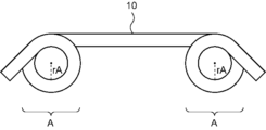
- FIG. 2 shows an overall view of the stent of the stent kit shown in FIG. 1 in a state where no insertion member is disposed in the lumen.
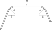
- FIG. 2 shows a partially enlarged view of the insertion member of the stent kit shown in FIG. 1 in a state where it is not placed in the lumen of the stent.
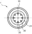
- 2 is a cross-sectional view taken along IV-IV of the stent kit shown in FIG. 1.
- FIG. FIG. 6 shows a cross-sectional view of a stent kit in another embodiment of the present invention, perpendicular to the extending direction of the stent.
- FIG. 2 shows a partially enlarged cross-sectional view of the stent kit shown in FIG. 1 along the extending direction of the insert member.
- 2 represents an overall view of a stent system comprising the stent kit shown in FIG. 1;
- FIG. FIG. 4 depicts an overall view of a stent system in another embodiment of the present invention.
- 9 shows an overall view of the protective tube of the stent system shown in FIG. 8 in a state where no stent is placed in the lumen;
- FIG. 1 is an overall view of a stent kit in which an insertion member is inserted into a lumen of a stent according to an embodiment of the present invention, and shows a state in which a holding element is brought into contact with an arcuate portion A of the stent.
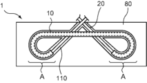
- FIG. 7 is a schematic diagram showing a state in which a holding element is brought into contact with an arcuate portion A of a stent in a stent kit in which an insertion member is inserted into a lumen of a stent according to another embodiment of the present invention.
- FIG. 1 is an overall view of a stent kit 1 in an embodiment of the present invention.
- the stent kit 1 includes a stent 10, an insertion member 20 inserted into the lumen of the stent 10, and a stent disposed outside the insertion member 20 and on the proximal side of the stent 10. It has an outer cylinder member 50.
- the stent kit 1 is a device that transports the stent 10 to a lesion site.
- the stent 10 is attached to the inner member 20 on which the outer cylinder member 50 is placed, and the stent 10 is transported to the lesion area, and the inner cavity is removed from the inner cavity of the stent 10 by pulling the inner member 20 toward the proximal side with respect to the outer cylinder member 50.
- the insertion member 20 is removed and the stent 10 is placed in the lesion.
- the proximal side refers to the user's proximal side with respect to the extending direction of the insertion member 20, and the distal side refers to the side opposite to the proximal side, that is, the side where treatment is performed with the stent kit 1. (points to the lesion side).
- the direction in which the inserting member 20 extends may be referred to as the longitudinal axis direction.
- the longitudinal axis direction of the inserting member 20 can be referred to as the perspective direction of the inserting member 20.
- FIG. 2 is an overall view of the stent 10 in a state where the insertion member 20 is not placed in the lumen of the stent 10.
- the stent 10 is a long object that has one end and the other end and has a lumen.
- the stent 10 is preferably a plastic stent.
- the material constituting the stent 10 examples include polyamide resin, polyester resin, polyurethane resin, polyolefin resin, fluorine resin, vinyl chloride resin, silicone resin, natural rubber, and the like. These may be used alone or in combination of two or more.
- the resin constituting the stent 10 is preferably at least one of a polyamide resin, a polyester resin, a polyurethane resin, a polyolefin resin, and a fluororesin.
- the material constituting the stent 10 is at least one of a polyamide resin, a polyester resin, a polyurethane resin, a polyolefin resin, and a fluorine resin
- the surface of the stent 10 has increased slipperiness and can be used to improve the lumen in the living body. It is possible to improve the insertion property.
- a tube made of resin, which is a raw material for the stent 10, can be manufactured using a conventional method such as extrusion molding or injection molding.
- the stent 10 has an arc portion A that is curved in an arc shape.
- the arcuate portion A is the portion where the stent 10 curves into an arc when the insertion member 20 is not placed in the inner cavity of the stent 10 and no external force other than gravity is applied to the stent 10. Point.
- the arc portion A has the function of contacting the in-vivo lumen and fixing the stent 10 to the in-vivo lumen.
- the stent 10 when the stent 10 is a bile duct stent, the stent 10 is placed distal to the narrowed part (obstructed part) of the bile duct or strays into the bile duct so that the stent 10 does not fall off from the bile duct toward the duodenum. In some cases, an arcuate portion A is placed near the papilla of the duodenum.
- the arcuate portion A may be located at one end of the stent 10, and is preferably located at both ends of the stent 10. That is, it is preferable that the stent 10 has arc portions A curved in an arc shape at both ends, one end and the other end. By having the arc portions A at both one end and the other end of the stent 10, it is possible to enhance the effect of fixing the stent 10 in the in-vivo lumen.
- the shape of the arc portion A may be a closed circular shape as shown in FIG. 2, or may be a semicircular arc shape where the circle is not closed. If the shape of the arc portion A is a closed circle, the effect of fixing the stent 10 in a predetermined position can be enhanced. Further, if the shape of the arc portion A is an arc shape in which the circle is not closed, the stent 10 can be easily inserted into a lumen in a living body.
- the insertion member 20 is inserted into the lumen of the stent 10.
- the insertion member 20 is a long object having one end and the other end.
- the stent 10 can be placed in the lesion by transporting the stent 10 to the lesion with the stent 10 attached to the insertion member 20 and removing the insertion member 20 from the lumen of the stent 10.
- the shape of the inserting member 20 in a state where it is not placed in the inner cavity of the stent 10 may be such that at least a portion in the extending direction of the inserting member 20 is curved in an arc shape. At least a portion in the direction may be linear, and the inserting member 20 may be linear from one end to the other end.
- the shape of the insertion member 20 before being disposed in the inner cavity of the stent 10 may have an arc portion B curved in an arc shape.
- the arcuate portion B is a curved portion of the inserting member 20 in an arcuate shape when the inserting member 20 is not placed in the inner cavity of the stent 10 and no external force other than gravity is applied to the inserting member 20. refers to the part that is
- the insert member 20 has a lumen extending from one end to the other end. Since the insertion member 20 has a lumen, when the stent 10 is transported to a diseased area, the guidewire can be inserted through the lumen of the insertion member 20, thereby improving the insertion performance.
- the cross-sectional shape of the outer shape of the inserting member 20 in a cross section perpendicular to the extending direction of the inserting member 20 is circular. Since the outer cross-sectional shape of the inserting member 20 is circular, the surface of the inserting member 20 is smooth, and even if it comes into contact with other objects such as the inner surface of the stent 10 or the wall of the lumen in the living body. , making it difficult to damage other objects.
- the cross-sectional shape of the lumen of the insert member 20 in a cross section perpendicular to the extending direction of the insert member 20 is as follows: Preferably, it is circular. Since the internal cavity of the internal insertion member 20 has a circular cross-sectional shape, the internal surface of the internal insertion member 20 is smooth, and a guide wire or the like can be smoothly inserted into the internal cavity of the internal insertion member 20. Become.
- the material constituting the inserting member 20 examples include polyamide resin, polyester resin, polyurethane resin, polyolefin resin, fluorine resin, vinyl chloride resin, silicone resin, natural rubber, and the like. These may be used alone or in combination of two or more.
- the material constituting the insert member 20 is preferably a polyamide resin, a polyester resin, a polyurethane resin, a polyolefin resin, or a fluororesin. Since the material constituting the insert member 20 is polyamide resin, polyester resin, polyurethane resin, polyolefin resin, or fluorine resin, the insert member 20 has good surface slipperiness and high insertion performance. can do.
- the outer cylindrical member 50 is an elongated member that has one end and the other end, and has an inner cavity.
- the inner insertion member 20 is inserted into the inner cavity of the outer cylinder member 50.
- the distal end of the outer cylinder member 50 is arranged more proximally than the proximal end of the stent 10. That is, the outer cylinder member 50 is disposed outside the inner insertion member 20 and closer to the proximal end of the stent 10.
- the stent 10 is attached to the inner member 20 on which the outer cylinder member 50 is placed, and the stent 10 is transported to the lesion area, and the inner cavity is removed from the inner cavity of the stent 10 by pulling the inner member 20 toward the proximal side with respect to the outer cylinder member 50.
- the insertion member 20 is removed, and the stent 10 can be placed in the lesion.
- Examples of the cross-sectional shape of the outer cylinder member 50 in a cross section perpendicular to the extending direction of the outer cylinder member 50 include a circle, a polygon, or a combination thereof. Among these, it is preferable that the external cross-sectional shape of the outer cylinder member 50 in a cross section perpendicular to the extending direction of the outer cylinder member 50 is circular. Since the outer cylindrical member 50 has a circular cross-sectional shape, the outer surface of the outer cylindrical member 50 is smooth, and even if the outer surface of the outer cylindrical member 50 comes into contact with the wall of the in-vivo lumen, it is less likely to be damaged. can do.
- the cross-sectional shape of the inner cavity of the outer cylinder member 50 in a cross section perpendicular to the extending direction of the outer cylinder member 50 is circular. Since the cross-sectional shape of the inner cavity of the outer cylinder member 50 is circular, the surface of the inner cavity of the outer cylinder member 50 is smooth, and the slidability of the outer cylinder member 50 with respect to the inner member 20 can be easily improved.
- the material constituting the outer cylinder member 50 examples include polyamide resin, polyester resin, polyurethane resin, polyolefin resin, fluorine resin, vinyl chloride resin, silicone resin, natural rubber, and the like. These may be used alone or in combination of two or more.
- the resin constituting the outer cylinder member 50 is preferably at least one of a polyamide resin, a polyester resin, a polyurethane resin, a polyolefin resin, and a fluororesin. Since the material constituting the outer cylinder member 50 is at least one of polyamide resin, polyester resin, polyurethane resin, polyolefin resin, and fluorine resin, the outer cylinder member 50 has a highly slippery surface and has good insertion performance. It can be a cylindrical member 50.
- the tube made of resin, which is the raw material for the outer cylinder member 50 can be manufactured using a conventional method such as extrusion molding or injection molding.
- FIG. 3 is a partially enlarged view of the insertion member 20 in a state where the insertion member 20 is not placed in the inner cavity of the stent 10.
- the minimum radius of curvature rA of the circular arc portion A is smaller than the minimum radius of curvature rB of the insert member 20. It's also small.
- the minimum radius of curvature rB of the inserting member 20 is the minimum curvature of the circular arc portion B that the inserting member 20 has. means radius rB.
- the minimum radius of curvature rA of the circular arc portion A is smaller than the minimum radius of curvature rB of the insertion member 20, so that the circular arc portion A of the stent 10
- the degree of curvature is different between the stent 10 and the inserting member 20, and the arc portion A of the stent 10 has a shape that is more curved than the inserting member 20.
- the arc portion A of the stent 10 is curved, and the arc portion A contacts the lumen in the living body, thereby fixing the stent 10 in the lumen in the living body. can.
- the inserting member 20 when the inserting member 20 is inserted into the inner cavity of the stent 10, the inserting member 20 reduces the curvature of the arcuate portion A of the stent 10, making it possible to approximate the shape of the arcuate portion A to a straight line. . As a result, the insertability of the stent 10 can be improved.
- the stent 10 is fed into the in-vivo lumen with the insertion member 20 inserted into the lumen of the stent 10, and transported to the target site.
- the stent 10 takes on a straight or nearly straight shape, thereby improving the insertability.
- the insertion member 20 is removed from the lumen of the stent 10.
- the shape of the arc portion A of the stent 10 returns to the shape before the insertion member 20 was inserted, or becomes a shape close to the shape before the insertion member 20 was inserted, and the arc portion A has a curved shape. becomes.
- the movement of the stent 10 can be prevented by the curved arc portion A coming into contact with the in-vivo lumen.
- the minimum radius of curvature rA of the circular arc portion A and the minimum radius of curvature rB of the insertion member 20 in a state where the insertion member 20 is not placed in the lumen of the stent 10 for example, The stent 10 and the stent 20 are taken out with the stent 10 and the stent 20 left still, and in the obtained image, the minimum radius of curvature rA of the arcuate portion A and One example is to measure the minimum radius of curvature rB of the interpolation member 20.
- the minimum radius of curvature rA of the circular arc portion A in a state where the insertion member 20 is not placed in the inner cavity of the stent 10 is 70% or less of the minimum radius of curvature rB of the insertion member 20, and 60% It is more preferably at most 50%, even more preferably at most 50%.
- the lower limit value of the ratio of the minimum radius of curvature rA of the circular arc portion A to the minimum radius of curvature rB of the insertion member 20 in a state where the insertion member 20 is not placed in the inner cavity of the stent 10 is not particularly limited. , for example, more than 0%, 0.1% or more, or 1% or more.
- the shape of the insertion member 20 in a state where it is not placed in the lumen of the stent 10 is linear. Since the inserting member 20 is linear, when the inserting member 20 is inserted into the inner cavity of the stent 10, the effect of reducing the curvature of the arc portion A of the stent 10 can be enhanced, and the stent 10 can be straightened. It becomes possible to improve the insertion property by having a shape like this.
- the inserting member 20 in a state where the inserting member 20 is disposed in the inner cavity of the stent 10, the inserting member 20 has a shaped section s1 curved in an arc shape, and a shaped section s1 that is longer than the shaped section s1. It has a straight unshaped section s2 located on the distal end side of the inserting member 20, and the length L2 of the unshaped section s2 in the extending direction of the inserting member 20 is It is preferable that it is longer than the length L1 of the shaping section s1 in the extending direction of the insert member 20.
- the shaped section s1 is a section where the extending direction of the inserting member 20 is curved in an arc shape
- the non-shaped section s2 is a section where the extending direction of the inserting member 20 is linear. It is an interval of a part.
- the length L2 of the non-shaped section s2 is longer than the length L1 of the shaped section s1, so that the distal end of the insertion member 20 A straight portion can be secured.
- the level difference that occurs between the tip of the insert member 20 and the guide wire can be reduced, and the insertability of the stent kit 1 is improved. be able to.
- the length L2 of the non-shaped section s2 in the extending direction of the inserting member 20 is preferably at least twice the length L1 of the shaping section s1 in the extending direction of the inserting member 20, and is 2.5 It is more preferably at least twice as large, and even more preferably at least 3 times.
- the length of the shaped section s1 can be It becomes easier to make the length L2 of the non-shaped section s2 sufficiently longer than L1.
- the length L2 of the non-shaped section s2 in the extending direction of the inserting member 20 is preferably 30 times or less the length L1 of the shaping section s1 in the extending direction of the inserting member 20, and 25 It is more preferably at most 20 times, and even more preferably at most 20 times.
- the length of the interpolation member 20 is prevented from becoming excessively long,
- the insertion member 20 can be easily placed in the lumen of the stent 10.
- the length L2 of the unshaped section s2 in the extending direction of the inserting member 20 is preferably 50 mm or less, more preferably 45 mm or less, and even more preferably 40 mm or less.
- the length of the insertion member 20 in the extending direction is less likely to become excessively long, and when the stent 10 is placed, the in-vivo tube It can make the cavity less likely to be damaged.
- the lower limit of the length L2 of the non-shaped section s2 in the extending direction of the inserting member 20 is not particularly limited, but may be, for example, 5 mm or more, 7 mm or more, or 10 mm or more.
- FIG. 4 is a cross-sectional view of the stent kit 1 perpendicular to the extending direction of the stent 10
- FIG. 5 is a cross-sectional view of the stent kit 1 in another embodiment perpendicular to the extending direction of the stent 10.
- the metal wire 30 be included in the metal wire 30.
- the metal wire 30 By having the metal wire 30 in at least a part of the portion of the inserting member 20 located in the circular arc portion A, the rigidity of the portion of the inserting member 20 having the metal wire 30 is increased.
- the inserting member 20 when the inserting member 20 is placed in the inner cavity of the stent 10, the effect of reducing the curvature of the arcuate portion A of the stent 10 by the inserting member 20 can be enhanced, and the insertability of the stent 10 is improved. It becomes easier.
- the metal wire 30 is preferably placed over 30% or more of the length of the arc portion A of the stent 10, and preferably over 50% of the length of the arc portion A of the stent 10. It is more preferable that it is arranged at 70% or more, it is even more preferable that it is arranged at 90% or more, and it is especially preferable that it is arranged at 100%.
- the metal wire 30 being disposed over 100% of the length of the arc portion A of the stent 10 means that the metal wire 30 is present over the entire length of the arc portion A.
- the metal wire 30 can be placed inside the stent 10 when the insertion member 20 is placed in the inner cavity of the stent 10. It becomes easier to reduce the curvature of the arcuate portion A, and it becomes possible to improve the insertability of the stent 10.
- the upper limit of the length of the metal wire 30 in the arc portion A is not particularly limited, but may be, for example, 100% or less.
- the length of the metal wire 30 in the extending direction of the insertion member 20 is preferably 30% or more, more preferably 50% or more, of the length of the circular arc portion A in the extending direction of the stent 10. It is more preferably 70% or more, even more preferably 90%, and particularly preferably 100% or more.
- the lower limit of the ratio of the length of the metal wire 30 to the length of the arcuate portion A within the above range, when the insertion member 20 is placed in the inner cavity of the stent 10, the metal wire 30 is placed in the arcuate portion A.
- the line 30 can be easily placed.
- the curvature of the arc portion A can be easily reduced by the insertion member 20.
- the upper limit of the ratio of the length of the metal wire 30 to the length of the arc portion A is not particularly limited, but may be, for example, 500% or less, 400% or less, or 300% or less.
- the number of metal wires 30 that the inserting member 20 has may be one, but preferably a plurality. Since the inserting member 20 has a plurality of metal wires 30, the rigidity of the portion of the inserting member 20 where the metal wires 30 are provided is further increased, and the arcuate portion A of the stent 10 due to the inserting member 20 is It becomes possible to enhance the effect of reducing the curvature of.
- the cross-sectional shape of the metal wire 30 in the cross section perpendicular to the extending direction of the inserting member 20 may be, for example, circular, polygonal, or a combination thereof. Among these, it is preferable that the cross-sectional shape of the metal wire 30 in a cross section perpendicular to the extending direction of the insertion member 20 is circular. Since the cross-sectional shape of the metal wire 30 is circular, when the metal wire 30 is pressed against the insert member 20 due to bending or the like, the insert member 20 is not torn by the metal wire 30, etc. Damage can be made less likely to occur.
- Examples of the material constituting the metal wire 30 include stainless steel such as SUS304 and SUS316, platinum, nickel, cobalt, chromium, titanium, tungsten, gold, copper, iron, manganese, aluminum, zinc, or alloys thereof.
- the material constituting the metal wire 30 is preferably a shape memory alloy.
- the metal wire 30 tends to have a straight shape or a shape with a large radius of curvature. Therefore, by inserting the insertion member 20 into the inner cavity of the stent 10, the curvature of the arc portion A of the stent 10 can be easily reduced.
- the shape memory alloy constituting the metal wire 30 preferably contains at least one selected from the group consisting of a nickel titanium alloy, a beta titanium alloy, an iron-manganese-silicon alloy, and a cobalt-chromium alloy. Since the shape memory alloy constituting the metal wire 30 contains at least one selected from the above group, the metal wire 30 has excellent elasticity, which reduces the curvature of the arcuate portion A of the stent 10. The effect can be increased.
- the metal wire 30 has higher straightness than the stent 10. Since the straightness of the metal wire 30 is higher than the straightness of the stent 10, the metal wire 30 makes it easier for the insertion member 20 to have a straight or nearly straight shape. As a result, by arranging the insertion member 20 in the inner cavity of the stent 10, the curvature of the stent 10 can be reduced, and the penetrability of the stent 10 can be easily improved. In addition, when the inserting member 20 has a lumen extending from one end to the other end, the inner lumen of the inserting member 20 is It is possible to easily insert a guide wire or the like.
- the metal wire 30 includes at least one of a stainless steel wire and a tungsten wire. Since the metal wire 30 includes at least one of a stainless steel wire and a tungsten wire, the straightness of the metal wire 30 tends to be higher than that of the stent 10. Therefore, the straightness of the inserting member 20 also increases, and it becomes possible to reduce the curvature of the stent 10 and improve the ability of the inserting member 20 to pass into the lumen.
- the metal wire 30 is fixed to the wall portion 21 of the insertion member 20.
- the metal wire 30 may be embedded and fixed inside the wall portion 21 of the insertion member 20, and as shown in FIG. It may be arranged in the inner cavity of the insertion member 20 and fixed to the surface of the wall portion 21 of the insertion member 20.
- the metal wire 30 may be fixed to the wall portion 21 of the inserting member 20 only at a portion in the extending direction of the metal wire 30, or may be fixed to the wall portion 21 of the inserting member 20 over the entire length in the extending direction of the metal wire 30. It may be fixed to the wall portion 21.
- the insertion member 20 has a hub 40 at its proximal end, and although not shown, the metal wire 30 is preferably fixed to the hub 40.
- the structure in which the metal wire 30 is fixed to the hub 40 include a structure in which the proximal portion of the metal wire 30 is fixed to the hub 40. Since the metal wire 30 is fixed to the hub 40, the proximal side of the metal wire 30 is fixed and supported by the hub 40, and the effect of increasing the rigidity and straightness of the entire inserting member 20 by the metal wire 30 is further enhanced. It becomes easier.
- the hub 40 has a guide wire port communicating with the inner cavity of the endoscopic member 20, and is used when introducing a guide wire into the inner cavity of the endoscopic member 20 or when injecting a contrast medium, a drug solution, etc. It is a member used for etc.
- FIG. 6 is a partially enlarged cross-sectional view of the stent kit 1 along the extending direction of the insertion member 20.
- the connecting means 60 is annular, and the insertion member 20 is disposed inside the ring of the connecting means 60.
- FIG. 6 in order to make it easier to understand the positional relationship between the connecting means 60 and the inserting member 20, the portion of the connecting means 60 that is present on the front side of the page is shown with a broken line.
- the connecting means 60 Since the stent 10 and the outer tube member 50 are connected by the connecting means 60, the force applied from the proximal side is easily transmitted to the stent 10 through the outer tube member 50, and the stent 10 is pushed out to the distal side. It is possible to facilitate the operation of transporting to the target site.
- the stent 10 has a first side hole 71 that communicates with the inner cavity of the stent 10
- the outer cylinder member 50 has a second side hole 72 that communicates with the inner cavity of the outer cylinder member 50.
- the connecting means 60 is inserted into the first side hole 71 and the second side hole 72. Since the connecting means 60 is inserted into the first side hole 71 of the stent 10 and the second side hole 72 of the outer cylinder member 50, the stent 10 and the outer cylinder member 50 can be easily connected by the connecting means 60, and The connection between the stent 10 and the outer cylinder member 50 can also be easily released, if necessary.
- the connecting means 60 only needs to be able to connect the stent 10 and the outer cylinder member 50.
- the configuration of the connecting means 60 includes, for example, a configuration in which the connecting means 60 forms one ring, and the inner member 20 and the outer cylinder member 50 are arranged inside the annular portion, or a configuration in which the connecting means 60 forms a plurality of rings. It has an annular part, the inner member 20 is arranged in one annular part, and the outer cylinder member 50 is arranged in the other annular part, and the connecting means 60 is rod-shaped, and the inner member 20 is arranged in one end. Examples include a configuration in which the member 20 is fixed and the outer cylinder member 50 is fixed to the other end.
- the connecting means 60 has an annular portion, and the insertion member 20 is preferably disposed inside the annular portion. Since the connecting means 60 has an annular portion and the insertion member 20 is arranged inside the annular portion, it is possible to remove the insertion member 20 from the annular portion, cut the annular portion, etc. Accordingly, the connection between the stent 10 and the outer cylinder member 50 can be easily released. Therefore, it becomes easier to indwell the stent 10 at the target site.
- the connecting means 60 is a suture. Since the connecting means 60 is a suture, the connecting means 60 can be made flexible while maintaining its durability, and the connecting means 60 is less likely to damage the stent 10 or the wall of the in-vivo lumen. can do.
- the connecting means 60 forms one annular part, and the inner member 20 and a part of the distal end of the outer cylinder member 50 are arranged inside the annular part of the connecting means 60. It is preferable that the As shown in FIG. 6, the structure in which the inner member 20 and a part of the distal end of the outer cylinder member 50 are disposed inside the annular portion of the connecting means 60 is such that the connecting means is inserted into the first side hole 71. In other words, two linear members constituting the connecting means 60 are disposed, and one linear member constituting the connecting means 60 is disposed in the second side hole 72.
- the inner insert member 20 can be inserted from inside the annular portion of the connecting means 60. Since the connecting means 60 is fixed to the outer cylindrical member 50 even after being removed, it is possible to prevent the connecting means 60 from falling off, thereby increasing safety.
- FIG. 7 is an overall view of the stent system 100 including the stent kit 1.
- the stent system 100 includes a stent kit 1 and a holding element 80 that holds the stent kit 1, and the holding element 80 is inserted into the lumen of the stent 10. It is preferable to hold the arc portion A in a state where the member 20 is inserted. Since the holding element 80 holds the arcuate part A with the insertion member 20 inserted into the inner cavity of the stent 10, the shape of the arcuate part A of the stent 10 can be maintained by the holding element 80. .
- the insertion member 20 prevents the curve of the arcuate portion A of the stent 10 from being excessively corrected into a straight line, the holding element 80 maintains the arcuate portion A of the stent 10, and the stent It is possible to prevent the arc portion A of the stent 10 from disappearing when the insertion member 20 is removed from the inner cavity of the stent 10.
- the stent 10 when the stent 10 is transported, the stent 10 can be shaped into a straight line or a shape close to a straight line by the inserting member 20 to improve the insertion property, and after the inserting member 20 is removed from the inner cavity of the stent 10 In this case, the curve of the arc portion A of the stent 10 is restored, and the stent system 100 in which the arc portion A contacts the in-vivo lumen and is less likely to be misaligned can be achieved.
- the retaining element 80 includes at least one of a mount, a blister, a clip, and a tape. That is, the material constituting the holding element 80 preferably includes at least one selected from the group consisting of a mount, a blister, a clip, and a tape. Retaining element 80 may include one or more of a mount, a blister, a clip, and tape. Blister refers to so-called blister packs, such as those in which a thin plate-like object made of synthetic resin with irregularities is assembled to a mount or thin plate-like object, or a thin plate-like object made of synthetic resin with grooves formed in it. . Since the holding element 80 includes at least one of a mount, a blister, a clip, and a tape, the holding element 80 can easily and firmly fix and hold the arc portion A of the stent 10.
- a method for holding the arcuate part A in the holding element 80 with the insertion member 20 inserted into the inner cavity of the stent 10 is to make holes or cuts in the paper material,
- the stent 10 may be inserted into a hole or a notch to fix and hold the arc portion A.
- the holding element 80 is a blister
- the stent 10 may be fitted into the unevenness of a thin plate-like object made of synthetic resin to fix and hold the arcuate portion A.
- the holding element 80 is a clip
- the clip may be attached to the stent 10 to fix and hold the arc portion A.
- the holding element 80 is a tape
- the tape may be attached to the stent 10 to fix and hold the arc portion A.
- the stent system 100 may further include other holding elements 81 that hold the insertion member 20, the portion of the stent 10 other than the arcuate portion A, and the like.
- the stent system 100 further includes another holding element 81 holding other parts, so that the stent system 100 can be stored easily. It is possible to prevent the insertion member 20 from falling off the stent 10 during storage or transportation, and from unintentionally contacting each other and causing damage to the members.
- FIG. 8 is an overall view of the stent system 100 in another embodiment
- FIG. 9 is an overall view of the protective tube 90 in a state where the stent 10 is not placed in the lumen.
- the stent system 100 further includes a protection tube 90, and the minimum radius of curvature rC of the protection tube 90 is larger than the minimum radius of curvature rA of the circular arc portion A.
- the stent 10 is inserted into the inner lumen of the protective tube 90. As shown in FIG.
- the minimum radius of curvature rC of the protective tube 90 is equal to the minimum radius of curvature rC of the circular arc portion C that the protective tube 90 has.
- the arc portion C is a portion where the protection tube 90 curves into an arc when the stent 10 is not placed in the inner lumen of the protection tube 90 and no external force other than gravity is applied to the protection tube 90. refers to
- the minimum radius of curvature rC of the protective tube 90 is measured with the stent 10 not inserted into the inner lumen of the protective tube 90.
- the minimum radius of curvature rC of the protective tube 90 in a state where the stent 10 is not inserted into the inner cavity of the protective tube 90 is equal to It is preferably larger than the minimum radius of curvature rA. Since the minimum radius of curvature rC of the protective tube 90 is larger than the minimum radius of curvature rA of the circular arc portion A, the degrees of curvature of the protective tube 90 and the circular arc portion A of the stent 10 are different, and the protective tube 90 is different from the circular arc portion A of the stent 10.
- the shape has a smaller degree of curvature than the arcuate portion A.
- the protective tube 90 has a linear shape or a shape that is closer to a linear shape compared to the arcuate portion A of the stent 10. Therefore, by inserting the stent 10 into the inner lumen of the protective tube 90, the protective tube 90 protects the stent 10 while reducing the curvature of the arcuate portion A of the stent 10, allowing the stent 10 to pass through the lumen. It becomes possible to improve sexual performance.
- the method is as follows: An example of this method is to leave the protective tube 90 still, take a photograph of the protective tube 90, and measure the minimum radius of curvature rC of the protective tube 90 in the obtained image.
- the protective tube 90 is a long object that has one end and the other end, and has an inner cavity.
- the length of the protective tube 90 from one end to the other end is preferably longer than the length of the stent 10 from one end to the other end. Since the protective tube 90 is longer than the stent 10, it becomes easier to protect the entire stent 10.
- the cross-sectional shape of the protective tube 90 in a cross section perpendicular to the extending direction of the protective tube 90 may be, for example, circular, polygonal, or a combination thereof.
- the external cross-sectional shape of the protective tube 90 in a cross section perpendicular to the extending direction of the protective tube 90 is circular. Since the outer cross-sectional shape of the protective tube 90 is circular, the outer surface of the protective tube 90 is smooth, and even if the outer surface of the protective tube 90 comes into contact with another object, it is less likely to be damaged.
- the cross-sectional shape of the inner cavity of the protective tube 90 in a cross section perpendicular to the extending direction of the protective tube 90 is circular. Since the cross-sectional shape of the inner cavity of the protective tube 90 is circular, the slidability of the inner surface of the protective tube 90 is increased, making it possible for the stent 10 to move smoothly through the inner cavity of the protective tube 90. .
- the material constituting the protective tube 90 examples include polyamide resin, polyester resin, polyurethane resin, polyolefin resin, fluorine resin, vinyl chloride resin, silicone resin, natural rubber, and the like. These may be used alone or in combination of two or more.
- the resin constituting the protective tube 90 is preferably at least one of a polyamide resin, a polyester resin, a polyurethane resin, a polyolefin resin, and a fluororesin.
- the material constituting the protective tube 90 is at least one of a polyamide resin, a polyester resin, a polyurethane resin, a polyolefin resin, and a fluororesin
- the protective tube 90 can have good slipperiness.
- a tube made of resin, which is a raw material for the protective tube 90 can be manufactured using a conventional method such as extrusion molding or injection molding.
- the delivery device of the present invention includes a stent, an insertion member inserted into the inner cavity of the stent, and an outer cylinder disposed outside the insertion member and proximal to the stent.
- the insertion member has a shape that is more linear than the arcuate portion of the stent, or has a curved shape that is close to a straight shape.
- the curve of the arcuate portion of the stent becomes linear or nearly linear due to the insertion member, making it easier to transport the stent to the diseased area.
- the minimum radius of curvature of the circular arc portion of the stent becomes larger than the minimum radius of curvature of the inserted member, so the stent after placement is Misalignment is less likely to occur.
- a method for manufacturing a stent kit according to the present invention includes a stent having a lumen extending longitudinally from a proximal side to a distal side and having an arcuate portion A curved in an arc shape;
- a method for producing a stent kit comprising an insertion member inserted into the lumen of the stent, comprising: a preparation step of preparing the stent; a placement step of arranging the insertion member in the lumen of the stent; The method includes a holding step of bringing a holding element into contact with the arcuate portion A of the stent.
- the inner lumen of the stent has an inner lumen extending in the longitudinal direction from the proximal side to the distal side and has an arc portion A curved in an arc shape.
- the method includes a holding step of bringing a holding element into contact with the circular arc portion A of the stent in a state in which the inserting member is arranged, so that the inserting member is, for example, linear or circular.
- the stent Even if the stent has a circular arc portion B curved in an arc shape, and the minimum radius of curvature rB in the circular arc portion B is larger than the minimum radius of curvature rA in the circular arc portion A of the stent, the stent can maintain the state in which the arc portion A is curved in an arc shape. Therefore, when the stent is transported to the lesioned area, the curve of the arcuate portion A of the stent becomes linear or nearly linear due to the insertion member, making it easier to transport the stent to the lesioned area.
- the minimum radius of curvature rA of the circular arc portion A of the stent is the minimum radius of curvature rB of the insertion member. Since the shape is larger than that of the stent, the stent placed in the lesion is less likely to be misaligned.
- the stent 10 is prepared, which has a lumen extending longitudinally from the proximal side to the distal side and has an arc portion A curved in an arc shape.
- FIG. 2 shows a configuration example of an embodiment of the stent 10 prepared in the preparation process. Note that the insertion member 20 is not arranged in the lumen of the stent 10 shown in FIG.
- the stent 10 may be prepared, which has a lumen extending longitudinally from the proximal side to the distal side and an arc portion A curved in an arc shape, or the stent 10
- the method may include a step of preparing a tube that is a raw material (hereinafter sometimes referred to as a raw material tube) and curving a part of the raw material tube into an arc shape to form the above-mentioned arcuate portion A.
- a method for forming the arc part A by curving a part of the raw material tube into an arc shape for example, inserting a long object into the inner cavity of the raw material tube, and curving a part of the raw material tube together with the long object into an arc shape.
- An example of this method is to heat the raw material tube in a curved state to form the arc portion A in the raw material tube.
- the placement step is a step of placing the insertion member 20 in the lumen of the stent 10 described above.
- FIG. 3 shows a configuration example of an embodiment of the insertion member 20 disposed in the lumen of the stent 10. Note that FIG. 3 shows a state in which the insertion member 20 is not placed in the lumen of the stent 10.
- the manufacturing method of the present invention may include a step of subjecting the inserting member 20 to a heat treatment to make it straight, before placing the inserting member 20 in the lumen of the stent 10.
- the heat treatment may be performed by heating, for example, at 80 to 150° C. for 1 to 2 hours while pulling both ends of the insert member 20.
- the holding element 80 is brought into contact with the arcuate portion A of the stent 10 in which the insertion member 20 is disposed in the inner cavity.
- the holding element 80 is a member that can hold the shape of the arcuate portion A of the stent 10.
- the material constituting the holding element 80 includes, for example, at least one selected from the group consisting of a mount, a synthetic resin, a clip, and a tape. Since the holding element 80 includes at least one of a mount, a synthetic resin, a clip, and a tape, the holding element 80 can easily and firmly hold the arc portion A of the stent 10.
- the synthetic resin of the material constituting the holding element 80 is preferably at least one of a polyamide resin, a polyester resin, a polyurethane resin, a polyolefin resin, and a fluorine resin, for example.
- the material constituting the holding element 80 is a synthetic resin
- the holding element 80 As a method for bringing the holding element 80 into contact with the arcuate portion A of the stent 10 in which the insertion member 20 is disposed in the inner cavity, when the holding element 80 is a mount, a hole or notch is made in the paper material, and the hole or notch is Another method is to insert the arcuate portion A of the stent 10 and maintain the shape of the arcuate portion A.
- the holding element 80 is made of synthetic resin
- a method of holding the arcuate portion A by fitting the arcuate portion A of the stent 10 into the unevenness of a thin plate-like object made of synthetic resin is exemplified.
- the holding element 80 is a clip
- a method for holding the arcuate portion A by attaching the clip to the arcuate portion A of the stent 10 is exemplified.
- the holding element 80 is a tape
- a method for holding the arcuate portion A of the stent 10 by attaching the tape to the arcuate portion A can be mentioned.
- FIG. 10 is a schematic diagram showing a state in which the holding element 80 is brought into contact with the stent kit 1 in which the insertion member 20 is disposed in the inner cavity of the stent 10.
- the stent 10 shown in FIG. 10 has closed circular arc portions A at one end and the other end, and a holding element 80 is abutted on each arc portion A. The shape is maintained.
- the holding element 80 shown in FIG. 10 is a tape, and by bringing the tape into contact with the arcuate portion A of the stent 10, the shape of the arcuate portion A is held.
- FIG. 11 is a schematic diagram showing another state in which the holding element 80 is brought into contact with the stent kit 1 in which the insertion member 20 is disposed in the inner cavity of the stent 10.
- the stent 10 shown in FIG. 11 is the same as that in FIG. 10, and has closed circular arc portions A at one end and the other end, and a holding element 80 abuts on each arc portion A. The shape of the arc portion A is maintained.
- the holding element 80 shown in FIG. 11 is a blister, and a groove 110 is formed in the blister, and the stent 10 is entirely embedded along the groove 110 of the blister, so that the shape of the arcuate portion A is maintained. There is.
- FIG. 12 is a schematic diagram showing another state in which the holding element 80 is brought into contact with the stent kit 1 in which the insertion member 20 is disposed in the inner cavity of the stent 10.
- the stent 10 shown in FIG. 12 has semicircular arc portions A in which the circle is not closed at one end and the other end, and a holding element 80 is abutted on each arc portion A. The shape of A is maintained.
- the holding element 80 shown in FIG. 12 is a blister, and a groove 110 is formed in the blister, and the stent 10 is entirely embedded along the groove 110 of the blister, so that the shape of the arcuate portion A is maintained. There is.
- the manufacturing method of the present invention preferably includes a sterilization step after the holding step.
- a sterilization step By sterilizing the holding element 80 with the holding element 80 in contact with the arcuate portion A of the stent 10, the portion of the insertion member 20 located in the arcuate portion A of the stent 10 is It has a shape that approximates the radius of curvature rA.
- the arcuate portion A of the stent 10 does not immediately become straight, and the shape of the arcuate portion A of the stent 10 is maintained for a certain period of time. can. Therefore, the stent 10 can be fixed in the lumen of the living body.
- the sterilization conditions are not particularly limited, but may be, for example, at 50 to 90°C for 8 to 15 hours.
- the stent kit 1 having the insertion member 20 can be used after moving the stent 10 distally or proximally with respect to the insertion member 20 before transporting the stent 10 to the in-vivo lumen. is preferred.
- the shape of the arcuate portion A of the stent 10 can be made closer to a linear shape. This makes it easier to insert the stent kit 1 into the lumen of the living body.
- the position of the stent 10 relative to the insertion member 20 may be moved by a doctor, but may also be moved by a medical professional other than a doctor. By having medical personnel other than the doctor move the device before surgery, the doctor can quickly perform the procedure.
- the movement distance of the stent 10 is preferably in the range of 1 mm or more and 50 mm or less, for example. By setting the moving distance of the stent 10 within the above range, the ability to insert the stent 10 into the lumen of the living body is improved.
- the insertion member has a circular arc portion B that is linear or curved in an arc shape, for example. Even if the minimum radius of curvature rB in is larger than the minimum radius of curvature rA in the arcuate portion A of the stent, the stent can maintain the state in which the arcuate portion A is curved into an arc. Therefore, when the stent is transported to the lesioned area, the curve of the arcuate portion A of the stent becomes linear or nearly linear due to the insertion member, making it easier to transport the stent to the lesioned area.
- the minimum radius of curvature rA of the circular arc portion A of the stent is the minimum curvature of the insertion member. Since the shape is larger than the radius rB, the stent placed in the lesion is less likely to be misaligned.
- Stent kit 10 Stent 20: Insertion member 21: Wall portion 30: Metal wire 40: Hub 50: Outer tube member 60: Connecting means 71: First side hole 72: Second side hole 80: Holding element 81: Other retention elements 90: Protective tube 100: Stent system 110: Groove A: Arc of the stent rA: Minimum radius of curvature at arc A B: Arc of the insert rB: Minimum radius of curvature at arc B C : Arc part of the protective tube rC: Minimum radius of curvature in arc part C s1: Shaped section s2: Unshaped section L1: Length of shaped section L2: Length of unshaped section
Landscapes
- Health & Medical Sciences (AREA)
- Engineering & Computer Science (AREA)
- Biomedical Technology (AREA)
- Life Sciences & Earth Sciences (AREA)
- Animal Behavior & Ethology (AREA)
- Veterinary Medicine (AREA)
- Public Health (AREA)
- Heart & Thoracic Surgery (AREA)
- General Health & Medical Sciences (AREA)
- Transplantation (AREA)
- Vascular Medicine (AREA)
- Oral & Maxillofacial Surgery (AREA)
- Cardiology (AREA)
- Surgery (AREA)
- Nuclear Medicine, Radiotherapy & Molecular Imaging (AREA)
- Medical Informatics (AREA)
- Molecular Biology (AREA)
- Gastroenterology & Hepatology (AREA)
- Pulmonology (AREA)
- Media Introduction/Drainage Providing Device (AREA)
Priority Applications (2)
| Application Number | Priority Date | Filing Date | Title |
|---|---|---|---|
| JP2024542817A JPWO2024043219A1 (https=) | 2022-08-22 | 2023-08-22 | |
| CN202380057682.7A CN119654117A (zh) | 2022-08-22 | 2023-08-22 | 支架套件、具有支架套件的支架系统以及支架套件的制造方法 |
Applications Claiming Priority (4)
| Application Number | Priority Date | Filing Date | Title |
|---|---|---|---|
| JP2022131982 | 2022-08-22 | ||
| JP2022-131982 | 2022-08-22 | ||
| JP2022-146169 | 2022-09-14 | ||
| JP2022146169 | 2022-09-14 |
Publications (1)
| Publication Number | Publication Date |
|---|---|
| WO2024043219A1 true WO2024043219A1 (ja) | 2024-02-29 |
Family
ID=90013357
Family Applications (1)
| Application Number | Title | Priority Date | Filing Date |
|---|---|---|---|
| PCT/JP2023/030079 Ceased WO2024043219A1 (ja) | 2022-08-22 | 2023-08-22 | ステントキット、ステントキットを有するステントシステム、およびステントキットの製造方法 |
Country Status (3)
| Country | Link |
|---|---|
| JP (1) | JPWO2024043219A1 (https=) |
| CN (1) | CN119654117A (https=) |
| WO (1) | WO2024043219A1 (https=) |
Cited By (1)
| Publication number | Priority date | Publication date | Assignee | Title |
|---|---|---|---|---|
| WO2025258456A1 (ja) * | 2024-06-12 | 2025-12-18 | 株式会社カネカ | カテーテル、治具、および、カテーテルの製造方法 |
Citations (5)
| Publication number | Priority date | Publication date | Assignee | Title |
|---|---|---|---|---|
| US5141502A (en) * | 1991-08-28 | 1992-08-25 | Macaluso Jr Joseph N | Ureteral stent |
| JP2010506685A (ja) * | 2006-10-16 | 2010-03-04 | ウィルソン−クック・メディカル・インコーポレーテッド | 非拡張性ステント |
| JP2017529894A (ja) * | 2014-08-12 | 2017-10-12 | ブライトウォーター メディカル インコーポレイテッド | カテーテルを連結および分断するためのシステムおよび方法 |
| JP2021141928A (ja) * | 2020-03-10 | 2021-09-24 | テルモ株式会社 | 保護具 |
| JP2022052207A (ja) * | 2020-09-23 | 2022-04-04 | 住友ベークライト株式会社 | 医療器具 |
-
2023
- 2023-08-22 JP JP2024542817A patent/JPWO2024043219A1/ja active Pending
- 2023-08-22 CN CN202380057682.7A patent/CN119654117A/zh active Pending
- 2023-08-22 WO PCT/JP2023/030079 patent/WO2024043219A1/ja not_active Ceased
Patent Citations (5)
| Publication number | Priority date | Publication date | Assignee | Title |
|---|---|---|---|---|
| US5141502A (en) * | 1991-08-28 | 1992-08-25 | Macaluso Jr Joseph N | Ureteral stent |
| JP2010506685A (ja) * | 2006-10-16 | 2010-03-04 | ウィルソン−クック・メディカル・インコーポレーテッド | 非拡張性ステント |
| JP2017529894A (ja) * | 2014-08-12 | 2017-10-12 | ブライトウォーター メディカル インコーポレイテッド | カテーテルを連結および分断するためのシステムおよび方法 |
| JP2021141928A (ja) * | 2020-03-10 | 2021-09-24 | テルモ株式会社 | 保護具 |
| JP2022052207A (ja) * | 2020-09-23 | 2022-04-04 | 住友ベークライト株式会社 | 医療器具 |
Cited By (1)
| Publication number | Priority date | Publication date | Assignee | Title |
|---|---|---|---|---|
| WO2025258456A1 (ja) * | 2024-06-12 | 2025-12-18 | 株式会社カネカ | カテーテル、治具、および、カテーテルの製造方法 |
Also Published As
| Publication number | Publication date |
|---|---|
| JPWO2024043219A1 (https=) | 2024-02-29 |
| CN119654117A (zh) | 2025-03-18 |
Similar Documents
| Publication | Publication Date | Title |
|---|---|---|
| CN109567991B (zh) | 输送鞘管 | |
| US7789915B2 (en) | Stent for implantation | |
| CN102791316B (zh) | 支架几何结构 | |
| CN108186176B (zh) | 植入物的输送系统 | |
| JP2017209532A (ja) | 複数の並行ガイドワイヤを有する医療用ガイドワイヤシステム | |
| WO2004018031A2 (en) | Guide wire | |
| CN103917198A (zh) | 微导管 | |
| CN111712292A (zh) | 引导延伸导管 | |
| US20070050006A1 (en) | Coaxial dilatation method for stent implantation | |
| WO2024043219A1 (ja) | ステントキット、ステントキットを有するステントシステム、およびステントキットの製造方法 | |
| KR102668695B1 (ko) | 의료용 관상체 반송 장치 | |
| JP7043589B2 (ja) | ステント | |
| JP7378460B2 (ja) | 医療用管状体搬送装置およびその製造方法 | |
| JP7378459B2 (ja) | 医療用管状体搬送装置およびその製造方法 | |
| JP2011255001A (ja) | カテーテル補助具およびカテーテルユニット | |
| JP7329043B2 (ja) | 医療用管状体搬送装置 | |
| JP7824929B2 (ja) | 医療用管状体搬送装置の製造方法 | |
| CN223336596U (zh) | 斑马导丝 | |
| JPWO2020158096A1 (ja) | バスケットカテーテル | |
| JP2567676Y2 (ja) | カテ−テル | |
| JP2018201575A (ja) | カテーテルおよびその製造方法 | |
| WO2022044488A1 (ja) | チューブステント | |
| KR102228845B1 (ko) | 양방향 요관 스텐트를 이용한 요관 스텐트 삽입 시술방법 | |
| WO2025177936A1 (ja) | 生体内留置具 | |
| CN121866028A (zh) | 医疗用具 |
Legal Events
| Date | Code | Title | Description |
|---|---|---|---|
| 121 | Ep: the epo has been informed by wipo that ep was designated in this application |
Ref document number: 23857328 Country of ref document: EP Kind code of ref document: A1 |
|
| WWE | Wipo information: entry into national phase |
Ref document number: 2024542817 Country of ref document: JP |
|
| WWE | Wipo information: entry into national phase |
Ref document number: 202380057682.7 Country of ref document: CN |
|
| WWP | Wipo information: published in national office |
Ref document number: 202380057682.7 Country of ref document: CN |
|
| NENP | Non-entry into the national phase |
Ref country code: DE |
|
| 122 | Ep: pct application non-entry in european phase |
Ref document number: 23857328 Country of ref document: EP Kind code of ref document: A1 |