WO2024042948A1 - コイル部品 - Google Patents
コイル部品 Download PDFInfo
- Publication number
- WO2024042948A1 WO2024042948A1 PCT/JP2023/026908 JP2023026908W WO2024042948A1 WO 2024042948 A1 WO2024042948 A1 WO 2024042948A1 JP 2023026908 W JP2023026908 W JP 2023026908W WO 2024042948 A1 WO2024042948 A1 WO 2024042948A1
- Authority
- WO
- WIPO (PCT)
- Prior art keywords
- mounting
- facing
- outer end
- surface facing
- metal terminal
- Prior art date
- Legal status (The legal status is an assumption and is not a legal conclusion. Google has not performed a legal analysis and makes no representation as to the accuracy of the status listed.)
- Ceased
Links
Images



Classifications
-
- H—ELECTRICITY
- H01—ELECTRIC ELEMENTS
- H01F—MAGNETS; INDUCTANCES; TRANSFORMERS; SELECTION OF MATERIALS FOR THEIR MAGNETIC PROPERTIES
- H01F27/00—Details of transformers or inductances, in general
- H01F27/28—Coils; Windings; Conductive connections
- H01F27/29—Terminals; Tapping arrangements for signal inductances
- H01F27/292—Surface mounted devices
-
- H—ELECTRICITY
- H01—ELECTRIC ELEMENTS
- H01F—MAGNETS; INDUCTANCES; TRANSFORMERS; SELECTION OF MATERIALS FOR THEIR MAGNETIC PROPERTIES
- H01F17/00—Fixed inductances of the signal type
- H01F17/04—Fixed inductances of the signal type with magnetic core
- H01F17/045—Fixed inductances of the signal type with magnetic core with core of cylindric geometry and coil wound along its longitudinal axis, i.e. rod or drum core
-
- H—ELECTRICITY
- H01—ELECTRIC ELEMENTS
- H01F—MAGNETS; INDUCTANCES; TRANSFORMERS; SELECTION OF MATERIALS FOR THEIR MAGNETIC PROPERTIES
- H01F27/00—Details of transformers or inductances, in general
- H01F27/28—Coils; Windings; Conductive connections
-
- H—ELECTRICITY
- H01—ELECTRIC ELEMENTS
- H01F—MAGNETS; INDUCTANCES; TRANSFORMERS; SELECTION OF MATERIALS FOR THEIR MAGNETIC PROPERTIES
- H01F27/00—Details of transformers or inductances, in general
- H01F27/28—Coils; Windings; Conductive connections
- H01F27/2823—Wires
-
- H—ELECTRICITY
- H01—ELECTRIC ELEMENTS
- H01F—MAGNETS; INDUCTANCES; TRANSFORMERS; SELECTION OF MATERIALS FOR THEIR MAGNETIC PROPERTIES
- H01F27/00—Details of transformers or inductances, in general
- H01F27/28—Coils; Windings; Conductive connections
- H01F27/2823—Wires
- H01F27/2828—Construction of conductive connections, of leads
-
- H—ELECTRICITY
- H01—ELECTRIC ELEMENTS
- H01F—MAGNETS; INDUCTANCES; TRANSFORMERS; SELECTION OF MATERIALS FOR THEIR MAGNETIC PROPERTIES
- H01F27/00—Details of transformers or inductances, in general
- H01F27/28—Coils; Windings; Conductive connections
- H01F27/29—Terminals; Tapping arrangements for signal inductances
-
- H—ELECTRICITY
- H01—ELECTRIC ELEMENTS
- H01F—MAGNETS; INDUCTANCES; TRANSFORMERS; SELECTION OF MATERIALS FOR THEIR MAGNETIC PROPERTIES
- H01F27/00—Details of transformers or inductances, in general
- H01F27/28—Coils; Windings; Conductive connections
- H01F27/30—Fastening or clamping coils, windings, or parts thereof together; Fastening or mounting coils or windings on core, casing, or other support
- H01F27/306—Fastening or mounting coils or windings on core, casing or other support
Definitions
- the present invention relates to a wire-wound coil component having a structure in which a wire is wound around a core, and particularly to the structure of a metal terminal made of a metal plate attached to the core.
- Patent Document 1 Japanese Unexamined Patent Publication No. 2017-199841
- the core has a winding core extending in the axial direction and a pair of flanges provided at opposite ends of the winding core in the axial direction.
- a metal terminal made of a metal plate is attached to each collar and fixed with an adhesive.
- a wire is wound around the winding core, and the wire is connected to a metal terminal.
- the flange connects the mounting surface facing the mounting board side, the top surface facing the opposite side of the mounting surface, and the mounting surface and the top surface during mounting. It has an inner end surface on which the end of the core portion in the axial direction is located, and an outer end surface facing opposite to the inner end surface.
- the metal terminal has a mounting surface facing portion and an outer end surface facing portion that respectively oppose the mounting surface and the outer end surface of the collar portion.
- the mounting surface facing part has a mounting connection part that is connected to a conductor on the mounting board side during mounting, and a wire connection part to which a wire is connected, and the mounting connection part and the wire connection part are separated from each other. There is.
- Patent Document 1 describes that laser welding is applied to connect the wire to the wire connection part. As described above, if the mounting connection portion and the wire connection portion are separated from each other, it is expected that heat during welding the wires will be less likely to be transmitted to the mounting connection portion.
- both the mounting connection portion and the wire connection portion that constitute the mounting surface facing portion of the metal terminal are continuous from the outer end surface facing portion via the bent portion.
- the external force applied to the wire connection portion during thermocompression bonding is applied to the outer end surface facing portion continuous to the wire connection portion. Furthermore, when the coil component is mounted on the mounting board, an external force applied to the mounting connection portion is also applied to the outer end surface facing portion continuous to the mounting connection portion. Such concentration of external force on the outer end surface facing portion may cause the terminal electrode to come off from the flange.
- an object of the present invention is to provide a coil with a structure that makes it difficult for external force to concentrate on a specific location of the coil component in the process of connecting the wire to the metal terminal and the process of mounting the coil component on the mounting board. We are trying to provide parts.
- the present invention provides a core having a winding core extending in the axial direction, a first collar and a second collar provided at opposite ends of the winding core in the axial direction, and a first collar.
- the present invention is directed to a coil component comprising an attached metal terminal made of a metal plate and at least one wire connected to the metal terminal and wound around a winding core.
- the first flange connects the mounting surface facing the mounting board, the top surface facing the opposite side of the mounting surface, and the mounting surface and the top surface during mounting, and the first flange connects the mounting surface facing the mounting board and the top surface facing the opposite side of the mounting surface. and an inner end surface on which the end in the axial direction of the winding core is located, an outer end surface facing opposite to the inner end surface, a first side surface and a second side surface connecting the inner end surface and the outer end surface and facing in opposite directions to each other. and a side surface.
- this invention is characterized by having the following configuration.
- the metal terminal has a mounting surface facing portion facing the mounting surface, an outer end surface facing portion facing the outer end surface, and a side facing portion facing at least one of the first side surface and the second side surface.
- the mounting surface facing part has a mounting connection part that can be connected to a conductor on the mounting board side during mounting, and a wire connection part to which a wire can be connected.
- the mounting connection part and the wire connection part are separated from each other.
- the mounting connection part is connected from either the outer end facing part or the side facing part via the bent part, and the wire connecting part is connected from the other of the outer end facing part or the side facing part through the bent part. There is.
- the mounting connection part and the wire connection part are not only separated from each other, but also the mounting connection part is connected to either the outer end face facing part or the side face facing part, while the wire connection part is Since it is connected to the other of the outer end facing part and the side facing part, the load to the mounting connection part is applied to either the outer end facing part or the side facing part, and the load to the wire connection part is applied to the outer end facing part.
- the load can be applied to either the side facing portion or the side facing portion, respectively, and these loads can be advantageously distributed. Therefore, the wire connection part can be made less susceptible to loads such as heat and stress applied to the mounting connection part, and the mounting connection part can be made less susceptible to the influence of loads such as heat and stress applied to the wire connection part.
- the metal terminal has not only a mounting surface facing portion facing the mounting surface and an outer end surface facing portion facing the outer end surface, but also a side facing portion facing at least one of the first side surface and the second side surface. Therefore, surface-to-surface opposition is realized at at least three locations between the metal terminal and the first flange.
- the load such as heat and stress exerted on the metal terminal can be advantageously dispersed, thereby making it difficult for the metal terminal to come off from the first flange.
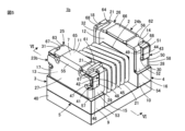
- FIG. 1 is a perspective view showing the appearance of a coil component 1 according to a first embodiment of the present invention, with mounting surfaces 7 and 8 facing upward.
- FIG. 2 is a perspective view showing a mounted state of the coil component 1 shown in FIG. 1.
- FIG. 3 is a perspective view for explaining a typical external force exerted on the coil component 1 in the mounted state shown in FIG. 2.
- FIG. 7 is a perspective view showing the appearance of a coil component 1a according to a second embodiment of the present invention, with mounting surfaces 7 and 8 facing upward.
- FIG. 7 is a perspective view showing the appearance of a coil component 1b according to a third embodiment of the present invention, with mounting surfaces 7 and 8 facing upward.
- 6 is a cross-sectional view taken along line VI-VI in FIG. 5.
- FIG. 5 is a cross-sectional view taken along line VI-VI in FIG. 5.
- a coil component 1 according to a first embodiment of the present invention will be described with reference to FIGS. 1 to 3.
- the coil component 1 includes a winding core 2 extending in the axial direction (L direction), and a pair of flanges provided at mutually opposite ends of the winding core 2 in the L direction, that is, first flanges. 3 and a second flange 4, the drum-shaped core 5 is provided.
- the core 5 is made of a magnetic material such as ferrite, a resin containing ferrite powder or metal magnetic powder, or a non-magnetic material such as alumina.
- the winding core 2 has a substantially rectangular cross-sectional shape in the drawings, it may also have a polygonal shape such as a hexagonal shape, a circular shape, an elliptical shape, or a combination thereof.
- the first flange 3 connects a mounting surface 7 that faces the mounting board 6 (see FIG. 2) side during mounting, a top surface 9 that faces the opposite side of the mounting surface 7, and the mounting surface 7 and the top surface 9.
- the inner end surface 11 faces the winding core 2 side and positions the end of the winding core 2 in the L direction
- the outer end surface 13 faces the opposite side of the inner end surface 11, and the inner end surface 11. It has a first side surface 15 and a second side surface 17 that connect the outer end surface 13 and face in opposite directions.
- the second flange 4 connects the mounting surface 8 facing the mounting board 6 side, the top surface 10 facing the opposite side of the mounting surface 8, and the mounting surface 8 and the top surface 10 during mounting.
- the dimensions of the core 5 are not limited, but as an example, the dimension in the L direction is 3.2 mm, which is a direction perpendicular to the L direction and in the direction in which the mounting surfaces 7 and 8 and the top surfaces 9 and 10 extend.
- the dimension in the direction (W direction) is 2.5 mm
- the dimension in the direction (T direction) connecting the mounting surfaces 7 and 8 and the top surfaces 9 and 10 is 1.8 mm.
- the coil component 1 constitutes a wire-wound inductor, for example, and includes a wire 21 wound around the winding core portion 2 of the core 5.
- the wire 21 includes, for example, a center wire made of a highly conductive metal such as copper, silver, or gold, and an insulating coating made of an electrically insulating resin such as polyamideimide, polyurethane, or polyesterimide that covers the center wire.
- the diameter of the center wire of the wire 21 does not matter, it is preferable to use one having a diameter of 80 ⁇ m or more and 200 ⁇ m or less, for example.
- the number of turns of the wire 21 on the winding core 2 does not matter.
- a pair of metal terminals 23 and 24 are attached to the flanges 3 and 4. More specifically, the first metal terminal 23 is attached to the first flange 3 , and the second metal terminal 24 is attached to the second flange 4 .
- the mutually opposite first and second ends of the wire 21 described above are connected to the first metal terminal 23 and the second metal terminal 24, respectively.
- the first metal terminal 23 and the second metal terminal 24 are each made of a single metal plate, and have substantially the same shape or a point-symmetrical shape.
- the metal plates constituting the metal terminals 23 and 24 for example, a plate formed by Ni plating and Sn plating on a base material made of phosphor bronze is used.
- the first metal terminal 23 includes a mounting surface facing portion 25, an outer end surface facing portion 27, and a first side surface facing portion 25 facing the mounting surface 7, the outer end surface 13, the first side surface 15, and the second side surface 17 of the first collar portion 3, respectively. portion 29 and a second side facing portion 31 .
- the second metal terminal 24 has a mounting surface facing portion 26, an outer end surface facing portion 28, and a first side surface facing the mounting surface 8, the outer end surface 14, the first side surface 16, and the second side surface 18 of the second collar portion 4, respectively. portion 30 and a second side facing portion 32 .
- the mounting surface facing portion 25 includes a first mounting surface facing end 61 on the first side surface 15 side, a second mounting surface facing end portion 63 on the second side surface 17 side, and a first mounting surface facing end portion 63 on the second side surface 17 side. It is divided into a mounting surface facing central portion 65 sandwiched between an end portion 61 and a second mounting surface facing end portion 63.
- the mounting surface facing center portion 65 is connected to the outer end surface facing portion 27 via the first bent portion 55, but the first mounting surface facing end portion 61 and the second mounting surface facing end portion 63 are respectively , are connected to the first side facing portion 29 and the second side facing portion 31 via the third bent portion 67.
- the mounting surface facing portion 26 includes a first mounting surface facing end 62 on the first side surface 16 side, a second mounting surface facing end portion 64 on the second side surface 18 side, and a first mounting surface facing end portion 64 on the second side surface 18 side. It is divided into a mounting surface facing central portion 66 sandwiched between a mounting surface facing end portion 62 and a second mounting surface facing end portion 64 .
- the mounting surface facing central portion 66 is connected to the outer end surface facing portion 28 via the first bent portion 56, but the first mounting surface facing end portion 62 and the second mounting surface facing end portion 64 are respectively , are connected to the first side facing portion 30 and the second side facing portion 32 via the third bent portion 68.
- the coil component 1 is mounted with metal terminals 23 and 24 connected to conductive lands 37 and 38 provided on the mounting board 6 via solder. At this time, solder is applied to central portions 65 and 66 of metal terminals 23 and 24 facing the mounting surfaces. In the mounted state shown in FIG. 2, the central parts 65 and 66 facing the mounting surface become “mounting connection parts" that can be connected to the conductive lands 37 and 38 on the mounting board 6 side.
- FIG. 2 shows a fillet 39 formed by solder that connects the conductive land 37 and the first metal terminal 23. As shown in FIG.
- the first end of the wire 21 is connected to one of the first mounting surface facing end 61 and the second mounting surface facing end 63, for example, the first mounting surface facing end 61.
- the second end of the wire 21 is connected to one of the first mounting surface facing end 62 and the second mounting surface facing end 64, for example, the second mounting surface facing end 64. be done. Therefore, the first mounting surface facing end 61 and the second mounting surface facing end 63 as well as the first mounting surface facing end 62 and the second mounting surface facing end 64 are "wire connection parts" to which the wire 21 can be connected. becomes.
- wires are connected to all of the first mounting surface facing end 61 and second mounting surface facing end 63, as well as the first mounting surface facing end 62 and second mounting surface facing end 64, which are “wire connection parts”. Not that it will be done.
- a “wire connection” is therefore to be understood as a part to which a wire can be connected.
- thermocompression bonding is applied to connect the wire 21 and the metal terminals 23 and 24 described above.
- the first end of the wire 21 is connected to the end 61 of the first metal terminal 23 facing the first mounting surface
- the second end of the wire 21 is connected to the end 61 of the second metal terminal 24 facing the second mounting surface.
- the excess portion of the tip of the wire 21 is cut and removed.
- the edges on the outer end faces 13 and 14 can be advantageously used.
- a top plate 40 is provided on the coil component 1 so as to connect the top surface 9 of the first flange 3 of the core 5 and the top surface 10 of the second flange 4.
- the top plate 40 is bonded to the core 5 with an adhesive.
- the adhesive for example, a thermosetting epoxy resin is used.
- Inorganic fillers such as silica fillers may be added to the adhesive to improve its thermal shock resistance.
- Examples of adhesive application methods include a printing method in which the adhesive is applied to the top plate 40, a method in which the top surfaces 9 and 10 sides of the flanges 3 and 4 of the core 5 are dipped in adhesive, and a method in which the adhesive is applied to the top plate 40 and the core 5.
- a method such as dispensing adhesive on both sides can be adopted.
- the material for the top plate 40 for example, a magnetic material such as ferrite, a resin containing ferrite powder or metal magnetic powder, or a non-magnetic material such as alumina is used.
- a resin coating may be applied. Note that the top plate 40 and the resin coating may not be provided.
- the first flange portion 3 resists the external force in the direction from the top surfaces 9 and 10 toward the mounting surfaces 7 and 8 in the T direction.
- the resistance can be maintained by the contact between the mounting surface 7 and the mounting surface facing portion 25 of the first metal terminal 23 and the contact between the mounting surface 8 of the second collar portion 4 and the mounting surface facing portion 26 of the second metal terminal 24. can.
- the metal terminals 23 and 24 can withstand external forces in at least the five directions described above without coming off from the flanges 3 and 4.
- This embodiment has a structure that makes it even more difficult for the metal terminals 23 and 24 to come off from the flanges 3 and 4. That is, the metal terminals 23 and 24 are directed away from the flange parts 3 and 4, at least the mounting surface facing parts 25 and 26 are away from the mounting surfaces 7 and 8, and at least the outer end face facing parts 27 and 28 are moved away from the outer end faces 13 and 14. It further includes a regulating section for regulating movement in the direction of separation.
- the regulating portion includes a first convex portion 41 provided on at least one of the first side surface 15 and the second side surface 17 of the first collar portion 3, and the first metal terminal 23.
- a notch 42 is located on at least one of the first side facing portion 29 and the second side facing portion 31 of the terminal 23 and receives the first convex portion 41.
- the regulating portion includes the first convex portion 43 provided on at least one of the first side surface 16 and the second side surface 18 of the second collar portion 4 and the first convex portion 43 of the second metal terminal 24 .
- a notch 44 is located on at least one of the side facing portion 30 and the second side facing portion 32 and receives the first convex portion 43.
- the first metal terminal 23 receives a relatively large external force.
- a large area can be secured for the outer end surface facing portion 27 and the mounting surface facing portion 25 of the metal terminal 23.
- the same can be said of the notch portion 44 in the second metal terminal 24. Therefore, the effect of making it difficult for the metal terminals 23 and 24 to come off from the flanges 3 and 4 can be further enhanced.
- the first convex portion 41 is provided on both the first side surface 15 and the second side surface 17 of the first collar portion 3, and the notch portion 42 is provided on the first metal terminal 23. It is located on both the first side facing portion 29 and the second side facing portion 31 of 23.
- the second metal terminal 24 the first convex portion 43 is provided on both the first side surface 16 and the second side surface 18 of the second collar portion 4
- the notch portion 44 is provided on the first side surface 16 and the second side surface 18 of the second collar portion 4 . It is located on both the first side facing portion 30 and the second side facing portion 32.
- the first convex portion 41 is provided on both the first side surface 15 and the second side surface 17 of the first collar portion 3, and the first convex portion 43 is provided on both the first side surface 16 and the second side surface of the second collar portion 4.
- the metal terminals 23 and 24 are difficult to come off from the flanges 3 and 4, and the effect can be further enhanced.
- the mounting surface facing portions 25 and 26 not only move in the direction away from the mounting surfaces 7 and 8, but also in the outer end surface. Movement of the opposing parts 27 and 28 in the direction away from the outer end surfaces 13 and 14 can also be restricted.
- the first convex portion 41 has a first rising wall 45 extending along the direction in which the top surface 9 of the first collar portion 3 and the mounting surface 7 face each other, and the outer end surface 13 and a second rising wall 46 extending along the direction in which the inner end surface 11 and the inner end surface 11 face each other, and the cutout portion 42 faces the first opposing wall 47 that faces the first rising wall 45 and the second rising wall 46.
- a second opposing wall 48 is provided.
- the first convex portion 43 has a first rising wall 49 extending along the direction in which the top surface 10 of the second collar portion 4 and the mounting surface 8 face each other, and the outer end surface 14 and the inner end surface. 12 and a second rising wall 50 extending along the opposite direction, the cutout portion 44 provides a first opposing wall 51 facing the first rising wall 49 and a second opposing wall 50 facing the second rising wall 50.
- a wall 52 is provided.
- the first rising walls 45 and 49 extend linearly in parallel with the inner end surfaces 11 and 12, respectively, and the second rising walls Preferably, 46 and 50 extend linearly parallel to mounting surfaces 7 and 8, respectively.
- the first convex portion 41 is connected to the outer end surface 13 and the mounting surface at the first side surface 15 and the second side surface 17.
- the notch portion 42 is located so as to be in contact with the corner where the first metal terminal 23 intersects with the inner end surface 11 side of the first side facing portion 29 and the second side facing portion 31 of the first metal terminal 23 and the top surface 9. It is located at a predetermined distance from the side edge.
- the first side facing portion 29 and the second side facing portion 31 have an L-shape that is biased toward the inner end surface 11 side and the top surface 9 side.
- the first convex section 43 is connected to the outer end surface 14 on the first side surface 16 and the second side surface 18.
- the cutout portion 44 is located so as to be in contact with the corner where the surface 8 intersects, and the cutout portion 44 is located at the edge of the inner end surface 12 side of the first side facing portion 30 and the second side facing portion 32 of the second metal terminal 24 and the top surface. It is located at a predetermined distance from the edge on the 10 side.
- the first side facing portion 30 and the second side facing portion 32 have an L-shape that is biased toward the inner end surface 12 side and the top surface 10 side.
- the area of each of the first protrusions 41 and 43 can be increased. Further, the rising walls along the mounting surfaces 7 and 8 in the first convex portions 41 and 43 are flush with the mounting surfaces 7 and 8, and the rising walls along the outer end surfaces 13 and 14 in the first convex portions 41 and 43 are on the outer end surface. Since it is flush with 13 and 14, it becomes easy to mold the core 5 including the first protrusions 41 and 43.
- the first flange 3 also includes a second convex portion 53 that faces at least a portion of the edge of the first metal terminal 23 on the top surface 9 side in a direction in which the top surface 9 and the mounting surface 7 face each other.
- the second flange 4 further includes a second protrusion that faces at least a portion of the edge of the second metal terminal 24 on the top surface 10 side in a direction in which the top surface 10 and the mounting surface 8 face each other. It is preferable to further include a section 54.
- the metal terminals 23 and 24 are protected against the rotational external force generated around the axis facing the W direction and the external force generated around the axis facing the L direction. It is possible to more reliably prevent it from coming off from parts 3 and 4.
- the external force in the rotational direction generated around the axis facing the W direction is caused by, for example, thermal expansion of the core 5 and the mounting board 6 when a temperature change occurs in a state where the coil component 1 and the mounting board 6 are mounted. This difference may be caused by the mounting board 6 thermally expanding more than the core 5.
- the second convex portion 53 is provided across the first side surface 15, the outer end surface 13, and the second side surface 17 of the first collar portion 3, and the second convex portion 54 is provided over the first side surface 15, the outer end surface 13, and the second side surface 17 of the first collar portion 3. It is provided over the side surface 16, the outer end surface 14, and the second side surface 18.
- the second convex portion 53 is opposed to the edge of the first side surface facing portion 29 and the second side surface facing portion 31 of the first metal terminal 23 on the top surface 9 side.
- the second convex portion 54 is provided so as to face the edge of the first side surface facing portion 30 and the second side surface facing portion 32 of the second metal terminal 24 on the top surface 10 side. Effective.
- outer end surfaces 27 and 28 of the metal terminals 23 and 24 may form a step on the outer end surfaces 13 and 14 side of the flanges 3 and 4, but the outer end surfaces 13 and 14 of the second convex portions 53 and 54 The portion located at contributes to eliminating or reducing such a level difference. Therefore, for example, it is possible to prevent the tip of a tweezers from getting stuck between the opposing outer end surfaces 27 and 28 of the metal terminals 23 and 24 and the outer end surfaces 13 and 14 of the flanges 3 and 4. can.
- the central parts 65 and 66 facing the mounting surface, which serve as “mounting connection parts”, and the end parts 61 to 64, facing the mounting surface, which serve as “wire connection parts” are separated from each other.
- the mounting surface facing ends 61 to 64 are continuous to the outer end surface facing parts 27 and 28 via the side facing parts 29 to 32.
- the mounting surface facing ends 61 to 64 are less susceptible to the effects of loads such as heat and stress exerted on the mounting surface facing central portions 65 and 66, and the mounting surface facing ends 61 to 64 are less susceptible to loads such as heat and stress exerted on the mounting surface facing central portions 65 and 66.
- the central portions 65 and 66 facing the mounting surface are less susceptible to the influence of the mounting surface. Therefore, the connection reliability between the mounting board 6 and the metal terminals 23 and 24 and the connection reliability between the metal terminals 23 and 24 and the wire 21 can be improved.
- the stress exerted on the mounting surface facing ends 61 to 64 includes, for example, the stress exerted on a specific one of the mounting surface facing ends 61 to 64 when the wire 21 is thermocompression bonded. If the mounting surface facing ends 61 to 64, which serve as "wire connection parts", were directly connected to the outer end surface facing parts 27 and 28 via the bent parts, the above-mentioned stress would cause the mounting surface facing ends 61 to 64 to 64 may tilt in the T direction about the ridgeline where the outer end surfaces 13 and 14 of the flanges 3 and 4 intersect with the mounting surfaces 7 and 8 as a fulcrum. In particular, the movement of the mounting surface facing ends 61 to 64 is large on the inner end surfaces 11 and 12 that are relatively far from the fulcrum.
- the wire 21 extends from the inner end surfaces 11 and 12 side, a connection failure of the wire 21 may occur or the wire 21 may be cut at the edge portion of the ends 61 to 64 facing the mounting surface.
- the wire 21 is more likely to be cut.
- the mounting surface facing ends 61 to 64 which serve as "wire connection parts" extend from the side surface facing parts 29 to 32, the ridge line where the side surfaces 15 to 18 and the mounting surfaces 7 and 8 intersect serves as a fulcrum, so the distance from the fulcrum to the inner end surfaces 11 and 12 of the mounting surface facing ends 61 to 64 is relatively short, so the amount of deflection of the mounting surface facing ends 61 to 64 during thermocompression bonding is It can be made smaller, and connection failures of the wire 21 can be made less likely to occur.
- the metal terminals 23 and 24 can be made difficult to come off from the collar parts 3 and 4.
- FIGS. 4 and 5 are diagrams corresponding to FIG. 1, showing a coil component 1a according to a second embodiment of the present invention and a coil component 1b according to a third embodiment, respectively.
- FIG. 6 is a cross-sectional view taken along line VI-VI in FIG.
- elements corresponding to those shown in FIG. 1 are given the same reference numerals, and redundant explanation will be omitted.
- the coil component 1a shown in FIG. 4 differs from the coil component 1 shown in FIG. 1 in the form of the mounting surface facing ends 61 to 64 of each of the metal terminals 23a and 24a. More specifically, among the mounting surface facing ends 61 to 64 that become “wire connection parts", the mounting surface facing ends 61 and 64 that actually become “wire connection parts” are connected to the flange parts 3 and 4. The height from the mounting surfaces 7 and 8 forms a slope that becomes lower from the outer end surfaces 13 and 14 toward the inner end surfaces 11 and 12.
- the wire 21 when connecting the wire 21 to a specific one of the ends 61 to 64 facing the mounting surface, the wire 21 can be pulled out while being guided smoothly. It is possible to reduce the possibility that 21 will be cut undesirably at the edges of the inner end surfaces 11 and 12 of the mounting surface facing ends 61 to 64.
- all of the mounting surface facing ends 61 to 64 serving as "wire connection parts” may form a slope that becomes lower from the outer end surfaces 13 and 14 side toward the inner end surfaces 11 and 12 side. According to this configuration, the wire 21 can be made to remain thick after crimping, so that the wire 21 is less likely to break.
- a central portion 65 facing the mounting surface as a "mounting connection section” and 66 are characterized by being higher than the mounting surface facing ends 61 to 64 serving as "wire connection parts".
- FIG. 6 the positional relationship between the mounting surface facing central portion 66 and the mounting surface facing ends 62 and 64 with respect to the mounting surface 8 of the second collar portion 4 is clearly shown.
- the end of the wire 21 connected to a specific one of the ends 61 to 64 facing the mounting surface is crushed by thermocompression bonding, but the above-mentioned height difference absorbs the thickness of the connected end of the wire 21. can do.
- the gap 69 (see FIG. 6) between the mounting surface facing central portions 65 and 66 and the mounting surfaces 7 and 8 of the collar portions 3 and 4 caused by this height difference is preferably 200 ⁇ m or less, for example.
- the gaps between the surface facing ends 61 to 64 and the mounting surfaces 7 and 8 of the flanges 3 and 4 are narrower than the gap 69.
- the coil parts to which this invention is directed include those that constitute a common mode choke coil, transformers, baluns, etc., in addition to those that constitute a single coil as in the illustrated embodiment. It's okay. Therefore, the number of wires can also be changed depending on the function of the coil component, and the number of metal terminals provided on each collar can also be changed accordingly. Typically, two metal terminals may be arranged side by side in the W direction on one flange.
- each metal terminal has a mounting surface facing part facing an area less than half of the width direction dimension of the mounting surface;
- the outer end surface has an outer end surface facing portion that faces an area that is less than half of the widthwise dimension of the outer end surface, and a side surface facing portion that faces one of the first side surface and the second side surface.
- the mounting surface facing part has a mounting connection part that can be connected to a conductor on the mounting board side during mounting and a wire connection part to which a wire can be connected, and the central part facing the mounting surface that becomes the mounting connection part. is less than half the widthwise dimension of the one shown, and has one end facing the mounting surface as a wire connection portion.
- the mounting surface facing central portion 65 is located between the first mounting surface facing end portion 61 and the second mounting surface facing end portion 63
- the mounting surface facing central portion 66 is located between the first mounting surface facing end portion 62 and the second mounting surface facing end portion 63.
- the wire 21 is located between the mounting surface facing ends 64, and the wire 21 is connected to the mounting surface facing central parts 65 and 66, and the wire 21 is connected to the mounting surface facing ends 61 and 62 or the second mounting surface facing ends 63 and 66. 64 and a conductive land on the mounting board may be connected.
- the first metal terminal 23 and the second metal terminal 24 have the same configuration, but one of the first metal terminal 23 and the second metal terminal 24, for example, the first Only the metal terminal 23 may have the characteristic configuration of the present invention.
- the second metal terminal 24 may be made of a metal plate that does not have the characteristic features of the present invention, or may be made of a conductive film obtained by firing a conductive paste, for example.
- Embodiments of this invention include the following.
- a core having a core portion extending in the axial direction, and a first flange portion and a second flange portion provided at mutually opposite ends of the core portion in the axial direction; a metal terminal made of a metal plate attached to the first flange; at least one wire connected to the metal terminal and wound around the core; Equipped with The first flange portion connects a mounting surface facing the mounting board during mounting, a top surface facing the opposite side of the mounting surface, and the mounting surface and the top surface, and an inner end face facing the core side and on which the end of the winding core in the axial direction is located; an outer end face facing the opposite side of the inner end face; and an inner end face connecting the inner end face and the outer end face to each other.
- the metal terminal includes a mounting surface facing portion facing the mounting surface, an outer end surface facing portion facing the outer end surface, and a side facing portion facing at least one of the first side surface and the second side surface.
- the mounting surface facing part has a mounting connection part that can be connected to a conductor on the mounting board side during mounting, and a wire connection part to which the wire can be connected, the mounting connection part and the wire connection part are separated from each other,
- the mounting connection portion is connected to one of the outer end surface facing portion and the side surface facing portion via a bent portion, and the wire connection portion is bent from either the outer end surface facing portion and the side surface facing portion. connected through the coil parts.
- ⁇ 2> The coil component according to ⁇ 1>, wherein the mounting connection portion is continuous from the outer end surface facing portion via a bending portion, and the wire connection portion is continuous from the side surface opposing portion via a bending portion.
- the metal terminal includes, as the side surface facing portions, a first side surface facing portion facing the first side surface and a second side surface facing portion facing the second side surface,
- the mounting surface facing part has a first wire connection part and a second wire connection part as the wire connection part,
- the width direction is the direction in which the first side surface and the second side surface face each other
- the first wire connection section and the second wire connection section are arranged so that the width of the mounting surface is equal to the width of the mounting surface, with the mounting connection section sandwiched therebetween. placed at each end of the direction,
- the wire is connected to at least one of the first wire connection part and the second wire connection part,
- the coil component according to any one of ⁇ 1> to ⁇ 3>.
- ⁇ 5> The coil component according to any one of ⁇ 1> to ⁇ 4>, wherein the mounting connection part is higher than the wire connection part with respect to the height of the first collar part from the mounting surface.
- a regulating portion for regulating movement of the metal terminal with respect to the first flange in a direction in which at least the mounting surface facing portion moves away from the mounting surface and at least in a direction in which the outer end surface facing portion moves away from the outer end surface; Furthermore,
- the regulating portion includes a first convex portion provided on at least one of the first side surface and the second side surface of each of the pair of collar portions, and a portion facing the first side surface and the second side surface of the metal terminal.
- the coil component according to any one of ⁇ 1> to ⁇ 6>, which is provided by a notch portion located on at least one of the opposing portions and receiving each of the first convex portions.
- Each of the pair of flange portions further includes a second convex portion that faces at least a portion of the edge of the metal terminal on the top surface side in a direction in which the top surface and the mounting surface face each other.
- ⁇ 10> Any one of ⁇ 1> to ⁇ 9>, further comprising a second metal terminal made of a metal plate attached to the second flange, the second metal terminal having the same configuration as the metal terminal. Coil parts listed.
Landscapes
- Engineering & Computer Science (AREA)
- Power Engineering (AREA)
- Microelectronics & Electronic Packaging (AREA)
- Coils Or Transformers For Communication (AREA)
Priority Applications (3)
| Application Number | Priority Date | Filing Date | Title |
|---|---|---|---|
| JP2024542667A JPWO2024042948A1 (https=) | 2022-08-23 | 2023-07-22 | |
| CN202380061036.8A CN119908020A (zh) | 2022-08-23 | 2023-07-22 | 线圈部件 |
| US19/058,365 US20250191834A1 (en) | 2022-08-23 | 2025-02-20 | Coil component |
Applications Claiming Priority (2)
| Application Number | Priority Date | Filing Date | Title |
|---|---|---|---|
| JP2022132156 | 2022-08-23 | ||
| JP2022-132156 | 2022-08-23 |
Related Child Applications (1)
| Application Number | Title | Priority Date | Filing Date |
|---|---|---|---|
| US19/058,365 Continuation US20250191834A1 (en) | 2022-08-23 | 2025-02-20 | Coil component |
Publications (1)
| Publication Number | Publication Date |
|---|---|
| WO2024042948A1 true WO2024042948A1 (ja) | 2024-02-29 |
Family
ID=90013231
Family Applications (1)
| Application Number | Title | Priority Date | Filing Date |
|---|---|---|---|
| PCT/JP2023/026908 Ceased WO2024042948A1 (ja) | 2022-08-23 | 2023-07-22 | コイル部品 |
Country Status (4)
| Country | Link |
|---|---|
| US (1) | US20250191834A1 (https=) |
| JP (1) | JPWO2024042948A1 (https=) |
| CN (1) | CN119908020A (https=) |
| WO (1) | WO2024042948A1 (https=) |
Citations (3)
| Publication number | Priority date | Publication date | Assignee | Title |
|---|---|---|---|---|
| JP2003332139A (ja) * | 2002-05-08 | 2003-11-21 | Tdk Corp | 表面実装型コイル部品 |
| JP2009177148A (ja) * | 2007-12-27 | 2009-08-06 | Tdk Corp | コイル部品の継線方法 |
| JP2021086969A (ja) * | 2019-11-29 | 2021-06-03 | Tdk株式会社 | コイル装置 |
-
2023
- 2023-07-22 CN CN202380061036.8A patent/CN119908020A/zh active Pending
- 2023-07-22 JP JP2024542667A patent/JPWO2024042948A1/ja active Pending
- 2023-07-22 WO PCT/JP2023/026908 patent/WO2024042948A1/ja not_active Ceased
-
2025
- 2025-02-20 US US19/058,365 patent/US20250191834A1/en active Pending
Patent Citations (3)
| Publication number | Priority date | Publication date | Assignee | Title |
|---|---|---|---|---|
| JP2003332139A (ja) * | 2002-05-08 | 2003-11-21 | Tdk Corp | 表面実装型コイル部品 |
| JP2009177148A (ja) * | 2007-12-27 | 2009-08-06 | Tdk Corp | コイル部品の継線方法 |
| JP2021086969A (ja) * | 2019-11-29 | 2021-06-03 | Tdk株式会社 | コイル装置 |
Also Published As
| Publication number | Publication date |
|---|---|
| US20250191834A1 (en) | 2025-06-12 |
| CN119908020A (zh) | 2025-04-29 |
| JPWO2024042948A1 (https=) | 2024-02-29 |
Similar Documents
| Publication | Publication Date | Title |
|---|---|---|
| US20250218643A1 (en) | Coil component | |
| JP6930433B2 (ja) | インダクタ素子 | |
| US10153081B2 (en) | Coil component | |
| US20060022788A1 (en) | Surface mount coil component | |
| JP6399010B2 (ja) | コイル部品 | |
| CN111128513B (zh) | 线圈部件和电子器件 | |
| KR20210059625A (ko) | 전자 부품 | |
| US20190156990A1 (en) | Coil component | |
| US11430602B2 (en) | Coil component | |
| CN109119234B (zh) | 线圈部件 | |
| US11862379B2 (en) | Coil component and electronic device | |
| JP7124429B2 (ja) | コイル部品およびコイル装置 | |
| CN114628122B (zh) | 线圈部件 | |
| WO2024042948A1 (ja) | コイル部品 | |
| WO2022070804A1 (ja) | コイル部品 | |
| US20230274875A1 (en) | Coil component | |
| JP7823757B2 (ja) | コイル部品 | |
| US11869704B2 (en) | Coil device | |
| JP4337312B2 (ja) | 低背型巻線コイル | |
| US20220148791A1 (en) | Coil component and method for manufacturing coil component | |
| WO2024042949A1 (ja) | コイル部品 | |
| JP7326704B2 (ja) | 電子部品 | |
| JP4702601B2 (ja) | コイル部品 | |
| CN116206852B (zh) | 线圈部件 | |
| JP7775849B2 (ja) | コア及びコイル部品 |
Legal Events
| Date | Code | Title | Description |
|---|---|---|---|
| 121 | Ep: the epo has been informed by wipo that ep was designated in this application |
Ref document number: 23857064 Country of ref document: EP Kind code of ref document: A1 |
|
| WWE | Wipo information: entry into national phase |
Ref document number: 2024542667 Country of ref document: JP |
|
| WWE | Wipo information: entry into national phase |
Ref document number: 202380061036.8 Country of ref document: CN |
|
| NENP | Non-entry into the national phase |
Ref country code: DE |
|
| WWP | Wipo information: published in national office |
Ref document number: 202380061036.8 Country of ref document: CN |
|
| 122 | Ep: pct application non-entry in european phase |
Ref document number: 23857064 Country of ref document: EP Kind code of ref document: A1 |