WO2024038580A1 - 受信電力推定装置、受信電力推定方法及びプログラム - Google Patents
受信電力推定装置、受信電力推定方法及びプログラム Download PDFInfo
- Publication number
- WO2024038580A1 WO2024038580A1 PCT/JP2022/031366 JP2022031366W WO2024038580A1 WO 2024038580 A1 WO2024038580 A1 WO 2024038580A1 JP 2022031366 W JP2022031366 W JP 2022031366W WO 2024038580 A1 WO2024038580 A1 WO 2024038580A1
- Authority
- WO
- WIPO (PCT)
- Prior art keywords
- evaluation
- received power
- mesh
- parameter
- radio wave
- Prior art date
- Legal status (The legal status is an assumption and is not a legal conclusion. Google has not performed a legal analysis and makes no representation as to the accuracy of the status listed.)
- Ceased
Links
Images




Classifications
-
- H—ELECTRICITY
- H04—ELECTRIC COMMUNICATION TECHNIQUE
- H04W—WIRELESS COMMUNICATION NETWORKS
- H04W16/00—Network planning, e.g. coverage or traffic planning tools; Network deployment, e.g. resource partitioning or cells structures
- H04W16/18—Network planning tools
Definitions
- the present invention relates to a received power estimating device, a received power estimating method, and a program.
- the radio wave propagation calculation formula for interference evaluation is determined by the directive of the Ministry of Internal Affairs and Communications (Reference 1: Internet ⁇ https://www.soumu.go.jp/main_content/000711787.pdf>). ing.
- a map is divided into meshes, and the received power is calculated for each received power evaluation point (hereinafter also referred to as evaluation point) determined at the center of the mesh or by any predetermined method within the mesh.
- evaluation point received power evaluation point
- the received power level was evaluated (for example, see Patent Documents 1 and 2).
- the mesh size used to evaluate the received power level and the mesh size used to calculate the values of parameters used in radio wave propagation calculations were the same.
- how to define an area for deriving parameter values that vary due to the influence of topography and features in a radio wave propagation calculation model depends on the individual radio wave propagation calculation model.
- ITU-R P Let us take as an example the case where 1411 is applied.
- ITU-R P The radio wave propagation calculation model of 1411 uses average road width and average building height as parameters. Let us consider that the mesh size when evaluating the received power level is 10 m on a side, and that the received power is determined for each mesh.
- an object of the present invention is to provide a received power estimation device, a received power estimation method, and a program capable of calculating estimated received power regardless of the size of a mesh that is a unit for evaluating received power.
- a received power estimating device sets an evaluation range, which is a geographical range for evaluating received power, to a received power evaluation mesh for calculating received power at evaluation points located within the evaluation range.
- an evaluation range dividing unit that performs a dividing process and a process of creating a parameter evaluation mesh in the evaluation range for obtaining a value of a parameter for radio wave propagation calculation used to calculate the received power at the evaluation point; and the received power a matching data generation unit that generates data indicating a correspondence relationship between an evaluation mesh and the parameter evaluation mesh, and a topography or feature that is included in the parameter evaluation mesh that corresponds to the received power evaluation mesh to which the evaluation point belongs.
- a received power calculation unit that calculates the received power at the evaluation point by a radio wave propagation calculation using the value of the radio wave propagation calculation parameter obtained based on the information.
- a received power estimation method sets an evaluation range, which is a geographical range for evaluating received power, to a received power evaluation mesh for calculating received power at evaluation points located within the evaluation range.
- a mesh dividing step of dividing the mesh a mesh creation step of creating a parameter evaluation mesh in the evaluation range for obtaining a value of a parameter for radio wave propagation calculation used to calculate the received power at the evaluation point, and a mesh creation step of the received power evaluation mesh.
- a matching data generation step of generating data indicating a correspondence relationship between the parameter evaluation mesh and the parameter evaluation mesh, based on information on topography or features included in the parameter evaluation mesh corresponding to the received power evaluation mesh to which the evaluation point belongs.
- a received power calculation step of calculating the received power at the evaluation point by a radio wave propagation calculation using the value of the radio wave propagation calculation parameter obtained.
- One aspect of the present invention is a program for causing a computer to function as the above-mentioned received power estimating device.
- FIG. 1 is a functional block diagram showing the configuration of a received power estimating device according to an embodiment of the present invention.
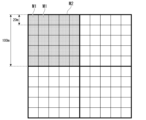
- FIG. 3 is a diagram showing the correspondence between the reception power evaluation mesh and the evaluation point side parameter evaluation mesh according to the same embodiment.
- FIG. 7 is a diagram illustrating an example of a match list according to the same embodiment.
- FIG. 3 is a flow diagram showing processing of the received power estimating device according to the embodiment.
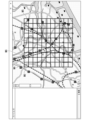
- FIG. 3 is a diagram illustrating an example of creating a base station-side parameter evaluation mesh according to the same embodiment. It is a figure which shows the example of creation of the evaluation point side parameter evaluation mesh by the same embodiment.
- FIG. 2 is a diagram illustrating an example of a hardware configuration of a received power estimating device according to the same embodiment.
- the received power estimating device of this embodiment determines the size of a mesh that is a unit of a geographical area for evaluating received power at a received power evaluation point, and the size of a mesh for calculating the value of a parameter for radio wave propagation calculation. Derived individually. Furthermore, the received power estimating device of this embodiment calculates the mesh size for calculating the value of the parameter for radio wave propagation calculation according to the frequency or according to the radio wave propagation calculation model used for calculating the received power. This is determined by determining a threshold value for the autocorrelation coefficient of fluctuations in received power. This makes it possible to derive parameter values in mesh units of appropriate size for calculating parameters for radio wave propagation calculation, regardless of the size of the mesh for evaluating received power.
- FIG. 1 is a functional block diagram showing the configuration of a received power estimating device 1 in an embodiment of the present invention.
- the received power estimating device 1 can be realized by, for example, a computer device. In FIG. 1, only functional blocks related to this embodiment are extracted and shown.
- the received power estimation device 1 includes a radio system information input section 11, a base station information input section 12, an evaluation range specification section 13, a map database (DB) 14, an evaluation range division section 15, and a base station side parameter calculation unit. section 16 , evaluation point side parameter calculation section 17 , matching list generation section 18 , received power calculation section 19 , and evaluation result output section 20 .
- DB map database
- the wireless system information input unit 11, the base station information input unit 12, and the evaluation range designation unit 13 are input units that input conditions that are a prerequisite for calculating the received power of radio waves radiated from a base station.
- the input unit receives information input by a user using, for example, a keyboard, a mouse, a touch panel, buttons, or keys. Alternatively, the input unit may receive information from another computer device connected via a network or read information from a computer-readable recording medium.
- the wireless system information input unit 11 inputs information regarding the wireless system, such as the effective radiated power and antenna pattern of the wireless system. Transmission power, antenna gain, feed line loss, etc. may be input as the effective radiated power.
- the base station information input unit 12 inputs base station information.
- the base station information includes information regarding the base station, such as the installation location, installation environment, and installation information of the base station.
- Latitude, longitude, height, etc. may be input as the installation location.
- the height may be ground clearance or altitude.
- the installation environment indoors or outdoors, etc. are input, and in the case of indoors, building penetration loss, etc. are further input.
- the north, south, east, west, and elevation angles of the antenna of the base station are input.
- the evaluation range specifying unit 13 specifies an evaluation range on the map according to the operator's operation or other conditions.
- the map DB 14 is a storage unit that stores map data.
- the map data includes information such as topographic information, building information, structure information, and land use information.
- the topographical information is information such as latitude, longitude, and altitude. Building information, structure information, and land use information are linked to topographic information.
- the building information and structure information are information on local features.
- the building information is information such as the outline and height of the building.
- the structure information is information such as the position of the road and the width of the road.
- Land use information includes information on building sites, sea level, lake level, farmland, forests, etc.
- the evaluation range dividing unit 15 divides the geographical evaluation range specified by the evaluation range specifying unit 13 to create a reception power evaluation mesh, a base station side parameter evaluation mesh, and an evaluation point side parameter evaluation mesh. Has a function.
- the evaluation range division section 15 includes a reception power evaluation mesh creation section 151, a radio wave propagation calculation model selection section 152, a base station side parameter evaluation mesh creation section 153, and an evaluation point side parameter evaluation mesh creation section 154.
- the reception power evaluation mesh creation unit 151 has a function of creating a reception power evaluation mesh by dividing the evaluation range according to input by the operator or other conditions.
- the reception power evaluation mesh is a unit for evaluating reception power at a reception power evaluation point.
- the radio wave propagation calculation model selection unit 152 has a function of selecting a radio wave propagation calculation model to be used for calculating the received power at the received power evaluation point. For example, the received power level is calculated using a radio wave propagation calculation model.
- the base station side parameter evaluation mesh creation unit 153 has a function of creating a base station side parameter evaluation mesh around the base station in the evaluation range when the radio wave propagation calculation model includes base station side parameters.
- the base station parameter evaluation mesh is an area for calculating values of base station parameters.
- the base station side parameters are radio wave propagation calculation parameters whose values vary depending on information around the base station.
- the evaluation point side parameter evaluation mesh creation unit 154 has a function of dividing the evaluation range and creating an evaluation point side parameter evaluation mesh when the radio wave propagation calculation model includes evaluation point side parameters.
- the evaluation point side parameter evaluation mesh is an area for calculating the value of the evaluation point side parameter.
- the evaluation point side parameter is a radio wave propagation calculation parameter whose value varies depending on information around the received power evaluation point.
- the base station side parameter calculation unit 16 has a function of deriving the value of the base station side parameter. That is, the base station side parameter calculation unit 16 determines whether among the base station side parameters used in the radio wave propagation calculation model, there are base station side parameters that need to be calculated based on map data such as topography and feature information. Decide whether or not. When the base station side parameter calculation unit 16 determines that there is such a base station side parameter, the base station side parameter calculation unit 16 calculates the base station side parameter based on the base station side parameter evaluation mesh created by the base station side parameter evaluation mesh creation unit 153. Information for calculating the value is acquired from the map DB 14. The base station side parameter calculation unit 16 derives the value of the base station side parameter using the acquired information. Information that is not acquired from the map DB 14, such as base station information, may be further used to derive the value of the base station side parameter.
- the evaluation point side parameter calculation unit 17 has a function of deriving the value of the evaluation point side parameter. That is, the evaluation point side parameter calculation unit 17 determines whether there are evaluation point side parameters that need to be calculated based on map data such as topography and feature information among the evaluation point side parameters used in the radio wave propagation calculation model. Decide whether or not. When the evaluation point side parameter calculation unit 17 determines that there is such an evaluation point side parameter, the evaluation point side parameter calculation unit 17 calculates the evaluation point side parameter based on the evaluation point side parameter evaluation mesh created by the evaluation point side parameter evaluation mesh creation unit 154. Information for calculating the value is acquired from the map DB 14. The evaluation point side parameter calculation unit 17 derives the value of the evaluation point side parameter using the acquired information. Information that is not acquired from the map DB 14 may be further used to derive the value of the evaluation point side parameter.
- the matching list generation unit 18 has a function of creating a matching list that matches the received power evaluation mesh, the base station side parameter evaluation mesh, and the evaluation point side parameter evaluation mesh created by the evaluation range division unit 15. .
- the matching list generation unit 18 further stores, in the matching list, the values of each base station side parameter and evaluation point side parameter used in the radio wave propagation calculation model.
- the received power calculation unit 19 calculates the received power for each received power evaluation point according to the radio wave propagation calculation model using at least part of the wireless system information, base station information, base station side parameters, and evaluation point side parameters. It has the ability to calculate.
- the evaluation result output section 20 has a function of outputting the calculation result of the received power calculation section 19 using an arbitrary output method. For example, the evaluation result output unit 20 may display the received power in each received power evaluation mesh on a map using a GUI (graphic user interface), or may output it as text information.
- FIG. 2 is a diagram showing the received power evaluation mesh M1 and the evaluation point side parameter evaluation mesh M2.
- FIG. 2 shows an example in which the size of the reception power evaluation mesh M1 and the size of the evaluation point side parameter evaluation mesh M2 are different.
- the size of the received power evaluation mesh M1 is 20 [m] x 20 [m].
- the size of the evaluation point side parameter evaluation mesh M2 is 100 [m] x 100 [m].
- the base station side parameter evaluation mesh is created for the vicinity of each base station within the evaluation range.
- the size of the base station side parameter evaluation mesh may be larger than, smaller than, or the same as the size of the evaluation point side parameter evaluation mesh M2.
- FIG. 3 is a diagram showing an example of a match list.
- the matching list includes the base station side parameter evaluation mesh, the base station side parameter values obtained from the base station side parameter evaluation mesh, the evaluation point side parameter evaluation mesh, and the evaluation points obtained from the evaluation point side parameter evaluation mesh. This is data that associates side parameter values with received power evaluation points.
- the base station side parameter evaluation mesh is represented by the identification information of the base station side parameter evaluation mesh
- the evaluation point side parameter evaluation mesh is represented by the identification information of the evaluation point side parameter evaluation mesh.
- a received power evaluation point belongs to any received power evaluation mesh. Therefore, the matching list shows the correspondence between the base station side parameter evaluation mesh, the evaluation point side parameter evaluation mesh, and the received power evaluation mesh to which the received power evaluation point belongs.
- the matching list shown in FIG. 3 includes one base station side parameter value and one evaluation point side parameter value, but there may be a plurality of base station side parameters and a plurality of evaluation point side parameters.
- FIG. 4 is a flow diagram showing the processing of the received power estimating device 1.
- an operator or others inputs wireless system information such as the effective radiated power and antenna pattern of the wireless system using the wireless system information input unit 11 (step S1).
- the operator or others inputs base station information including the base station installation location and designations of various setting values used for calculating the received power level using the base station information input unit 12 (step S2). Note that the order of inputs in step S1 and step S2 may be reversed.
- the operator or others inputs selection of an evaluation range through the evaluation range designation unit 13 (step S3).
- the operator may select the evaluation range by specifying the evaluation range on a GUI such as a map displayed on the display included in the received power estimating device 1. This may be done by inputting information in text, or by a combination of these selection methods.
- the received power evaluation mesh creating unit 151 divides the evaluation range selected in step S3 into received power evaluation meshes (step S4).
- the division of the received power evaluation mesh may be specified by the number of meshes, the mesh size, or a combination of these specifying methods.
- the designation of division of the reception power evaluation mesh may be inputted by the evaluation range designation unit 13 or may be stored in the evaluation range division unit 15 in advance.
- the radio wave propagation calculation model selection unit 152 selects a radio wave propagation calculation method (step S5).
- the radio wave propagation calculation model selection unit 152 may select one radio wave propagation calculation model as the radio wave propagation calculation method, or may select a plurality of radio wave propagation calculation models according to the distance between the base station and the received power evaluation point or other conditions. You may select a calculation method that combines calculation models.
- the radio wave propagation calculation model selection unit 152 uses information such as frequency included in the input wireless system information, whether the received power evaluation point is indoors or outdoors, and the visibility between the base station and the received power evaluation point.
- the radio wave propagation calculation model is selected depending on whether or not there is a radio wave propagation calculation model.
- the radio wave propagation calculation model is selected for each combination of an evaluation point or received power evaluation mesh and a base station or base station side parameter evaluation mesh, for example.
- the evaluation range dividing unit 15 After selecting the radio wave propagation calculation method, the evaluation range dividing unit 15 performs processing to derive parameter values according to the selected calculation method. First, the base station-side parameter evaluation mesh creation unit 153 determines whether the base station-side parameters are used in the calculation method selected in step S5 (step S6).
- step S6 When the base station side parameter evaluation mesh creation unit 153 determines that the base station side parameters are used in step S6 (step S6: YES), it performs the process of step S7. That is, the base station side parameter evaluation mesh creation unit 153 creates a base station side parameter evaluation mesh for deriving the value of the base station side parameter in the evaluation range selected in step S3 (step S7).
- the base station side parameter calculation unit 16 reads map data of the area corresponding to the base station side parameter evaluation mesh from the map DB 14 for each base station side parameter evaluation mesh created in step S7, and calculates the map data included in the read map data.
- the base station side parameter values are calculated using the information (step S8).
- step S6 determines in step S6 that the base station side parameters are not used (step S6: NO), or after the process in step S8, the received power estimating device 1 performs step S9. Process. That is, the evaluation point side parameter evaluation mesh creation unit 154 determines whether the evaluation point side parameter is used in the calculation method selected in step S5 (step S9).
- step S9 When the evaluation point side parameter evaluation mesh creation unit 154 determines that the evaluation point side parameter is used in step S9 (step S9: YES), it performs the process of step S10. That is, the evaluation point side parameter evaluation mesh creation unit 154 divides the evaluation range selected in step S3 into evaluation point side parameter evaluation meshes for deriving the values of the evaluation point side parameters (step S10).
- the evaluation point side parameter calculation unit 17 reads the map data of the area corresponding to the evaluation point side parameter evaluation mesh from the map DB 14 for each evaluation point side parameter evaluation mesh divided in step S10, and calculates the map data included in the read map data. The value of the evaluation point side parameter is calculated using the information (step S11).
- the match list generation unit 18 generates a match list (step S12).
- the matching list includes the received power evaluation mesh divided in step S4, the base station parameter evaluation mesh divided in step S7, and the base station parameter values calculated for the base station parameter evaluation mesh in step S8. This is data that associates the evaluation point side parameter evaluation mesh divided in step S9 with the value of the evaluation point side parameter calculated for the evaluation point side parameter evaluation mesh in step S10.
- received power evaluation points belonging to the received power evaluation mesh are set as information on the received power evaluation mesh.
- step S9 If the evaluation point side parameter evaluation mesh creation unit 154 determines in step S9 that the evaluation point side parameter is not used (step S9: NO), or after the process in step S12, the received power calculation unit 19 executes the process in step S13.
- the received power calculation unit 19 calculates the received power for each received power evaluation point using the radio wave propagation calculation method selected in step S5 (step S13).
- the received power calculation unit 19 calculates the value of the base station side parameter calculated for the base station side parameter evaluation mesh associated with the received power evaluation mesh to which the received power evaluation point belongs, and The value of the evaluation point side parameter calculated for the evaluation point side parameter evaluation mesh associated with the received power evaluation mesh to which the received power evaluation point belongs is read from the matching list.
- the received power calculation unit 19 adds the value of the read base station side parameter and the evaluation point side parameter to the radio wave propagation calculation method selected in step S5 for the received power evaluation point or the received power evaluation mesh to which the received power evaluation point belongs. By using the value, the received power level at the received power evaluation point is calculated. Note that when there are multiple base stations, the received power level is calculated for each combination of received power evaluation points and base stations.
- the evaluation result output unit 20 outputs an evaluation result indicating the received power level of each received power evaluation point calculated in step S13 (step S14).
- the base station side parameter evaluation mesh and the evaluation point side parameter evaluation mesh depends on the radio wave propagation calculation model and frequency. These parameters are modeled taking into consideration the influence of topography and terrestrial objects. Therefore, it is necessary to take into account that there is a correlation between the representative point and other points in the mesh in the calculation of the radio wave propagation calculation model used.
- the representative point is the installation position of the base station in the case of the base station side, and is, for example, the center point of the evaluation point side parameter evaluation mesh in the case of the received power evaluation point side.
- the received power Pr is calculated by the following equation (1).
- the propagation loss amount L in the case of outdoor visibility is calculated by the following equation (2).
- the value of d RD is calculated by inputting the value of d k obtained by inputting a value from 0 to 4 for k in the following formula (4) and inputting the value into the above formula (3).
- the value of L dRD is obtained by inputting a value from 0 to 4 for k in the following equation (6) to obtain all L dk values, and then calculating the value within the range of the conditions of the above equation (5). Calculated by inputting the value.
- the average building height h r is the average value of the heights of buildings around the base station. That is, the average building height hr is a base station side parameter.
- FIG. 5 is a diagram showing an example of creating a base station side parameter evaluation mesh when calculating the average building height around the base station.
- the base station side parameter evaluation mesh creation unit 153 creates base station side parameter evaluation meshes M3 and M4 using squares of a predetermined size centered on the positions of the two base stations B1 and B2.
- the base station parameter calculation unit 16 reads map data of the area corresponding to the base station parameter evaluation mesh from the map DB 14.
- the base station side parameter calculation unit 16 calculates the average building height h r based on the height of each building indicated by the building information included in the read map data.
- the road width w is the average value of the road widths around the received power evaluation point. That is, the road width w is an evaluation point side parameter.
- FIG. 6 is a diagram showing an example of creating an evaluation point-side parameter evaluation mesh when calculating the average road width around the reception power evaluation point.
- the evaluation point side parameter evaluation mesh generation unit 154 divides the evaluation range M5 into square meshes of a predetermined size, and creates an evaluation point side parameter evaluation mesh M6.
- the evaluation point side parameter calculation unit 17 reads map data of the area corresponding to the evaluation point side parameter evaluation mesh M6 from the map DB 14.
- the evaluation point side parameter calculation unit 17 calculates the road width w based on the position and road width of the road indicated by the structure information included in the read map data.
- the transmission power P T , transmission antenna gain G T , base station feed line loss L f , reception antenna gain G R , frequency f, and wavelength ⁇ are input in step S1 or step S2.
- the distance d between the base station and the reception power evaluation point is determined by the reception power calculation unit 19, for example, from the installation location of the base station obtained from the base station information and topographical information (latitude, longitude, and altitude) included in the map data. It is calculated using the position of the received power evaluation point obtained.
- the road angle ⁇ is calculated, for example, by the evaluation point side parameter calculation unit 17 using information on the position of the road and the installation location and installation method of the base station obtained from the base station information.
- the information on the position of the road is obtained from the structure information included in the map data of the area corresponding to the evaluation point side parameter evaluation mesh.
- the height h2 of the received power evaluation point is obtained, for example, by the received power calculation unit 19 from topographical information included in the map data.
- the received power estimating device 1 creates a base station side parameter evaluation mesh and/or an evaluation point side parameter evaluation mesh, separately from the received power evaluation mesh. Thereby, regardless of the size of the reception power evaluation mesh, it is possible to create a mesh of an appropriate size for deriving the values of parameters used in radio wave propagation calculations.
- the evaluation point side parameter evaluation mesh creation unit 154 takes 100 [m] on each side from the center of the mesh created for deriving the value of the evaluation point side parameter. It is conceivable to create an evaluation point-side parameter evaluation mesh with a size of [m].
- the received power evaluation mesh, the base station side parameter evaluation mesh, and the evaluation point side parameter evaluation mesh are rectangular in the above description, they may be other than rectangular.
- the mesh size for calculating the received power and the mesh size for calculating the value of the radio wave propagation calculation parameter can be set independently. It is possible to calculate the received power of radio waves at each received power evaluation point with good accuracy regardless of the mesh size of the received power.
- the received power estimating device 1 may be realized by a plurality of computer devices connected to a network.
- each functional unit of the received power estimating device 1 can be implemented by any one of the plurality of computer devices.
- the map DB 14 and other functional units may be implemented by different computer devices.
- the same functional unit may be realized by a plurality of computer devices.
- FIG. 7 is a device configuration diagram showing an example of the hardware configuration of the received power estimating device 1.
- the received power estimating device 1 includes a processor 71 , a storage section 72 , a communication interface 73 , and a user interface 74 .
- the processor 71 is a central processing unit that performs calculations and control.
- the processor 71 is, for example, a CPU (central processing unit) or a GPU (graphics processing unit).
- the processor 71 reads a program from the storage unit 72 and executes it.
- the storage unit 72 further includes a work area when the processor 71 executes various programs.
- the communication interface 73 is communicably connected to other devices.
- the user interface 74 is an input device such as a keyboard, a pointing device (mouse, tablet, etc.), a button, a touch panel, or a display device such as a display. A human operation is input through the user interface 74 .
- At least some of the functions of the received power estimating device 1 described above are realized by the processor 71 reading a program from the storage unit 72 and executing it.
- the program of the received power estimating device 1 may be recorded on a computer-readable recording medium.
- the computer-readable recording medium is, for example, a portable medium such as a flexible disk, magneto-optical disk, ROM, or CD-ROM, or a storage device such as a hard disk built into a computer system.
- the program of the received power estimating device 1 may be transmitted via a telecommunications line.
- the functions of the received power estimating device 1 may be realized using hardware such as an ASIC (Application Specific Integrated Circuit), a PLD (Programmable Logic Device), or an FPGA (Field Programmable Gate Array).
- the map data DB2 may be realized using the storage unit 72.
- the wireless system information input unit 11, the base station information input unit 12, and the evaluation range designation unit 13 may be realized using the user interface 74.
- the received power estimating device includes an evaluation range dividing section, a matching data generating section, and a received power calculating section.
- the evaluation range dividing unit performs processing to divide the evaluation range, which is a geographical range for evaluating received power, into received power evaluation meshes for calculating received power at evaluation points located within the evaluation range, and evaluation point A process of creating a parameter evaluation mesh in the evaluation range for obtaining the values of parameters for radio wave propagation calculation used in calculating the received power in is performed.
- the matching data generation unit generates data indicating the correspondence between the reception power evaluation mesh and the parameter evaluation mesh.
- the matching data generation section corresponds to, for example, the matching list generation section 18 of the embodiment.
- the received power calculation unit performs radio wave propagation calculation using the value of the radio wave propagation calculation parameter obtained based on the information on the topography or features included in the parameter evaluation mesh corresponding to the received power evaluation mesh to which the evaluation point belongs. , calculate the received power at the evaluation point.
- the size of the parameter evaluation mesh is determined by setting a threshold value for the autocorrelation coefficient of fluctuations in radio wave propagation, depending on the frequency of radio waves received at the evaluation point or according to the radio wave propagation calculation model used for radio wave propagation calculation. You may also decide based on this. For example, the size of the parameter evaluation mesh is set so that the autocorrelation coefficient of fluctuations in radio wave propagation is greater than or equal to a threshold value, depending on the frequency of radio waves received at the evaluation point, or depending on the radio wave propagation calculation model used for radio wave propagation calculation. It may be determined as follows.
- the evaluation range dividing unit may select a radio wave propagation calculation model to be used for radio wave propagation calculation according to the distance between the evaluation point and a wireless device that emits radio waves to the evaluation point.
- the evaluation range dividing unit performs processing of dividing the evaluation range into first parameter evaluation meshes for calculating the values of the first radio wave propagation calculation parameters using topography or feature information around the evaluation point, and evaluation.
- a second parameter evaluation mesh for calculating the value of the second radio wave propagation calculation parameter using information on the topography or features around the wireless device that emits radio waves to a point is installed at the installation position of the wireless device in the evaluation range. You may also perform processing to create the area around the .
- the matching data generation unit generates data indicating a correspondence relationship between the reception power evaluation mesh, the first parameter evaluation mesh, and the second parameter evaluation mesh.
- the received power calculation unit calculates the value of the first radio wave propagation calculation parameter calculated based on the information on topography or features included in the first parameter evaluation mesh corresponding to the received power evaluation mesh to which the evaluation point belongs, and the evaluation The evaluation point is determined by radio wave propagation calculation using the value of the second radio wave propagation calculation parameter calculated based on the information of the topography or features included in the second parameter evaluation mesh corresponding to the reception power evaluation mesh to which the point belongs. Calculate the received power at .
- Received power estimation device 11 Radio system information input section 12 Base station information input section 13 Evaluation range specification section 14 Map DB 15 Evaluation range division section 17 Evaluation point side parameter calculation section 18 Matching list generation section 19 Received power calculation section 20 Evaluation result output section 71 Processor 72 Storage section 73 Communication interface 74 User interface 151 Received power evaluation mesh creation section 152 Radio wave propagation calculation Model selection section 153 Base station side parameter evaluation mesh creation section 154 Evaluation point side parameter evaluation mesh creation section
Landscapes
- Engineering & Computer Science (AREA)
- Computer Networks & Wireless Communication (AREA)
- Signal Processing (AREA)
- Monitoring And Testing Of Transmission In General (AREA)
- Mobile Radio Communication Systems (AREA)
Priority Applications (2)
| Application Number | Priority Date | Filing Date | Title |
|---|---|---|---|
| PCT/JP2022/031366 WO2024038580A1 (ja) | 2022-08-19 | 2022-08-19 | 受信電力推定装置、受信電力推定方法及びプログラム |
| JP2024541374A JP7804236B2 (ja) | 2022-08-19 | 2022-08-19 | 受信電力推定装置、受信電力推定方法及びプログラム |
Applications Claiming Priority (1)
| Application Number | Priority Date | Filing Date | Title |
|---|---|---|---|
| PCT/JP2022/031366 WO2024038580A1 (ja) | 2022-08-19 | 2022-08-19 | 受信電力推定装置、受信電力推定方法及びプログラム |
Publications (1)
| Publication Number | Publication Date |
|---|---|
| WO2024038580A1 true WO2024038580A1 (ja) | 2024-02-22 |
Family
ID=89941727
Family Applications (1)
| Application Number | Title | Priority Date | Filing Date |
|---|---|---|---|
| PCT/JP2022/031366 Ceased WO2024038580A1 (ja) | 2022-08-19 | 2022-08-19 | 受信電力推定装置、受信電力推定方法及びプログラム |
Country Status (2)
| Country | Link |
|---|---|
| JP (1) | JP7804236B2 (https=) |
| WO (1) | WO2024038580A1 (https=) |
Citations (3)
| Publication number | Priority date | Publication date | Assignee | Title |
|---|---|---|---|---|
| JP2017158141A (ja) * | 2016-03-04 | 2017-09-07 | 株式会社国際電気通信基礎技術研究所 | コンピュータに実行させるためのプログラム、そのプログラムを搭載した計算装置、およびプログラムを記録したコンピュータ読み取り可能な記録媒体 |
| JP2020191555A (ja) * | 2019-05-22 | 2020-11-26 | Kddi株式会社 | 受信電力推定装置、受信電力推定方法およびプログラム |
| JP2021093673A (ja) * | 2019-12-12 | 2021-06-17 | 日本放送協会 | 世帯代表点算出装置、電界強度算出装置及びプログラム |
-
2022
- 2022-08-19 JP JP2024541374A patent/JP7804236B2/ja active Active
- 2022-08-19 WO PCT/JP2022/031366 patent/WO2024038580A1/ja not_active Ceased
Patent Citations (3)
| Publication number | Priority date | Publication date | Assignee | Title |
|---|---|---|---|---|
| JP2017158141A (ja) * | 2016-03-04 | 2017-09-07 | 株式会社国際電気通信基礎技術研究所 | コンピュータに実行させるためのプログラム、そのプログラムを搭載した計算装置、およびプログラムを記録したコンピュータ読み取り可能な記録媒体 |
| JP2020191555A (ja) * | 2019-05-22 | 2020-11-26 | Kddi株式会社 | 受信電力推定装置、受信電力推定方法およびプログラム |
| JP2021093673A (ja) * | 2019-12-12 | 2021-06-17 | 日本放送協会 | 世帯代表点算出装置、電界強度算出装置及びプログラム |
Also Published As
| Publication number | Publication date |
|---|---|
| JP7804236B2 (ja) | 2026-01-22 |
| JPWO2024038580A1 (https=) | 2024-02-22 |
Similar Documents
| Publication | Publication Date | Title |
|---|---|---|
| US6889053B1 (en) | Likelihood-based geolocation prediction algorithms for CDMA systems using pilot strength measurements | |
| CN1951027B (zh) | 无线网络里的位置确定和位置跟踪 | |
| EP2659697B1 (en) | Method for the prediction of coverage areas of a cellular network | |
| CN111818555A (zh) | 一种基于虚拟建站的无线电监测站点覆盖范围评估分析方法 | |
| US11418272B2 (en) | Radio wave environment display device and method for displaying radio wave environment | |
| US7171210B2 (en) | Method and apparatus for network planning | |
| JP2004524751A (ja) | 放射経路損失の測定に基づく予測方法 | |
| CN108513305B (zh) | 一种目标区域的基站选址方法、装置及设备 | |
| US20090144028A1 (en) | Method and apparatus of combining mixed resolution databases and mixed radio frequency propagation techniques | |
| JP2006311547A (ja) | レシーバシステムにおけるrfレシーバの位置を評価し、最適化する方法及びシステム | |
| US20200412463A1 (en) | Radio wave environment display device and radio wave environment display method | |
| WO2020245976A1 (ja) | 置局設計装置、置局設計方法及びプログラム | |
| CN112910583A (zh) | 干扰能量的确定方法和装置 | |
| KR101504357B1 (ko) | 측정 데이터를 이용한 무선망 최적화용 지형 지물 정보 추출 방법 | |
| Tayebi et al. | Development of a web-based simulation tool to estimate the path loss in outdoor environments using openstreetmaps [wireless corner] | |
| JP2018032939A (ja) | 品質推定装置及び品質推定方法 | |
| Filiposka et al. | Terrain-aware three-dimensional radio-propagation model extension for NS-2 | |
| JP4152249B2 (ja) | 電波伝搬特性推定装置、電波伝搬特性推定方法および電波伝搬特性推定プログラム | |
| WO2024038580A1 (ja) | 受信電力推定装置、受信電力推定方法及びプログラム | |
| Sangkusolwong et al. | Indoor wifi signal prediction using modelized heatmap generator tool | |
| JP2006287685A (ja) | 電波伝搬の推定プログラム、電波伝搬の推定方法、この方法を実行する装置 | |
| US20220174520A1 (en) | Arrival rate estimation apparatus, arrival rate estimation method and program | |
| KR101355363B1 (ko) | 고속 전파 해석 장치 및 그 방법 | |
| Međedović et al. | Softwares for urban electromagnetic wave propagation modeling | |
| CN106612510A (zh) | 室内覆盖设计的方法和装置 |
Legal Events
| Date | Code | Title | Description |
|---|---|---|---|
| 121 | Ep: the epo has been informed by wipo that ep was designated in this application |
Ref document number: 22955753 Country of ref document: EP Kind code of ref document: A1 |
|
| WWE | Wipo information: entry into national phase |
Ref document number: 2024541374 Country of ref document: JP |
|
| NENP | Non-entry into the national phase |
Ref country code: DE |
|
| 122 | Ep: pct application non-entry in european phase |
Ref document number: 22955753 Country of ref document: EP Kind code of ref document: A1 |