WO2024038580A1 - Received signal power estimation device, received signal power estimation method, and program - Google Patents
Received signal power estimation device, received signal power estimation method, and program Download PDFInfo
- Publication number
- WO2024038580A1 WO2024038580A1 PCT/JP2022/031366 JP2022031366W WO2024038580A1 WO 2024038580 A1 WO2024038580 A1 WO 2024038580A1 JP 2022031366 W JP2022031366 W JP 2022031366W WO 2024038580 A1 WO2024038580 A1 WO 2024038580A1
- Authority
- WO
- WIPO (PCT)
- Prior art keywords
- evaluation
- received power
- mesh
- parameter
- radio wave
- Prior art date
Links
- 238000000034 method Methods 0.000 title claims abstract description 26
- 238000011156 evaluation Methods 0.000 claims abstract description 377
- 238000004364 calculation method Methods 0.000 claims abstract description 131
- 238000012876 topography Methods 0.000 claims abstract description 18
- 238000009434 installation Methods 0.000 claims description 13
- 238000010586 diagram Methods 0.000 description 13
- 238000012545 processing Methods 0.000 description 9
- 238000004891 communication Methods 0.000 description 4
- 230000005540 biological transmission Effects 0.000 description 3
- 239000000969 carrier Substances 0.000 description 1
- 230000035515 penetration Effects 0.000 description 1
- 238000010187 selection method Methods 0.000 description 1
Images


Classifications
-
- H—ELECTRICITY
- H04—ELECTRIC COMMUNICATION TECHNIQUE
- H04W—WIRELESS COMMUNICATION NETWORKS
- H04W16/00—Network planning, e.g. coverage or traffic planning tools; Network deployment, e.g. resource partitioning or cells structures
- H04W16/18—Network planning tools
Definitions
- the present invention relates to a received power estimating device, a received power estimating method, and a program.
- the radio wave propagation calculation formula for interference evaluation is determined by the directive of the Ministry of Internal Affairs and Communications (Reference 1: Internet ⁇ https://www.soumu.go.jp/main_content/000711787.pdf>). ing.
- a map is divided into meshes, and the received power is calculated for each received power evaluation point (hereinafter also referred to as evaluation point) determined at the center of the mesh or by any predetermined method within the mesh.
- evaluation point received power evaluation point
- the received power level was evaluated (for example, see Patent Documents 1 and 2).
- the mesh size used to evaluate the received power level and the mesh size used to calculate the values of parameters used in radio wave propagation calculations were the same.
- how to define an area for deriving parameter values that vary due to the influence of topography and features in a radio wave propagation calculation model depends on the individual radio wave propagation calculation model.
- ITU-R P Let us take as an example the case where 1411 is applied.
- ITU-R P The radio wave propagation calculation model of 1411 uses average road width and average building height as parameters. Let us consider that the mesh size when evaluating the received power level is 10 m on a side, and that the received power is determined for each mesh.
- an object of the present invention is to provide a received power estimation device, a received power estimation method, and a program capable of calculating estimated received power regardless of the size of a mesh that is a unit for evaluating received power.
- a received power estimating device sets an evaluation range, which is a geographical range for evaluating received power, to a received power evaluation mesh for calculating received power at evaluation points located within the evaluation range.
- an evaluation range dividing unit that performs a dividing process and a process of creating a parameter evaluation mesh in the evaluation range for obtaining a value of a parameter for radio wave propagation calculation used to calculate the received power at the evaluation point; and the received power a matching data generation unit that generates data indicating a correspondence relationship between an evaluation mesh and the parameter evaluation mesh, and a topography or feature that is included in the parameter evaluation mesh that corresponds to the received power evaluation mesh to which the evaluation point belongs.
- a received power calculation unit that calculates the received power at the evaluation point by a radio wave propagation calculation using the value of the radio wave propagation calculation parameter obtained based on the information.
- a received power estimation method sets an evaluation range, which is a geographical range for evaluating received power, to a received power evaluation mesh for calculating received power at evaluation points located within the evaluation range.
- a mesh dividing step of dividing the mesh a mesh creation step of creating a parameter evaluation mesh in the evaluation range for obtaining a value of a parameter for radio wave propagation calculation used to calculate the received power at the evaluation point, and a mesh creation step of the received power evaluation mesh.
- a matching data generation step of generating data indicating a correspondence relationship between the parameter evaluation mesh and the parameter evaluation mesh, based on information on topography or features included in the parameter evaluation mesh corresponding to the received power evaluation mesh to which the evaluation point belongs.
- a received power calculation step of calculating the received power at the evaluation point by a radio wave propagation calculation using the value of the radio wave propagation calculation parameter obtained.
- One aspect of the present invention is a program for causing a computer to function as the above-mentioned received power estimating device.
- FIG. 1 is a functional block diagram showing the configuration of a received power estimating device according to an embodiment of the present invention.
- FIG. 3 is a diagram showing the correspondence between the reception power evaluation mesh and the evaluation point side parameter evaluation mesh according to the same embodiment.
- FIG. 7 is a diagram illustrating an example of a match list according to the same embodiment.
- FIG. 3 is a flow diagram showing processing of the received power estimating device according to the embodiment.
- FIG. 3 is a diagram illustrating an example of creating a base station-side parameter evaluation mesh according to the same embodiment. It is a figure which shows the example of creation of the evaluation point side parameter evaluation mesh by the same embodiment.
- FIG. 2 is a diagram illustrating an example of a hardware configuration of a received power estimating device according to the same embodiment.
- the received power estimating device of this embodiment determines the size of a mesh that is a unit of a geographical area for evaluating received power at a received power evaluation point, and the size of a mesh for calculating the value of a parameter for radio wave propagation calculation. Derived individually. Furthermore, the received power estimating device of this embodiment calculates the mesh size for calculating the value of the parameter for radio wave propagation calculation according to the frequency or according to the radio wave propagation calculation model used for calculating the received power. This is determined by determining a threshold value for the autocorrelation coefficient of fluctuations in received power. This makes it possible to derive parameter values in mesh units of appropriate size for calculating parameters for radio wave propagation calculation, regardless of the size of the mesh for evaluating received power.
- FIG. 1 is a functional block diagram showing the configuration of a received power estimating device 1 in an embodiment of the present invention.
- the received power estimating device 1 can be realized by, for example, a computer device. In FIG. 1, only functional blocks related to this embodiment are extracted and shown.
- the received power estimation device 1 includes a radio system information input section 11, a base station information input section 12, an evaluation range specification section 13, a map database (DB) 14, an evaluation range division section 15, and a base station side parameter calculation unit. section 16 , evaluation point side parameter calculation section 17 , matching list generation section 18 , received power calculation section 19 , and evaluation result output section 20 .
- DB map database
- the wireless system information input unit 11, the base station information input unit 12, and the evaluation range designation unit 13 are input units that input conditions that are a prerequisite for calculating the received power of radio waves radiated from a base station.
- the input unit receives information input by a user using, for example, a keyboard, a mouse, a touch panel, buttons, or keys. Alternatively, the input unit may receive information from another computer device connected via a network or read information from a computer-readable recording medium.
- the wireless system information input unit 11 inputs information regarding the wireless system, such as the effective radiated power and antenna pattern of the wireless system. Transmission power, antenna gain, feed line loss, etc. may be input as the effective radiated power.
- the base station information input unit 12 inputs base station information.
- the base station information includes information regarding the base station, such as the installation location, installation environment, and installation information of the base station.
- Latitude, longitude, height, etc. may be input as the installation location.
- the height may be ground clearance or altitude.
- the installation environment indoors or outdoors, etc. are input, and in the case of indoors, building penetration loss, etc. are further input.
- the north, south, east, west, and elevation angles of the antenna of the base station are input.
- the evaluation range specifying unit 13 specifies an evaluation range on the map according to the operator's operation or other conditions.
- the map DB 14 is a storage unit that stores map data.
- the map data includes information such as topographic information, building information, structure information, and land use information.
- the topographical information is information such as latitude, longitude, and altitude. Building information, structure information, and land use information are linked to topographic information.
- the building information and structure information are information on local features.
- the building information is information such as the outline and height of the building.
- the structure information is information such as the position of the road and the width of the road.
- Land use information includes information on building sites, sea level, lake level, farmland, forests, etc.
- the evaluation range dividing unit 15 divides the geographical evaluation range specified by the evaluation range specifying unit 13 to create a reception power evaluation mesh, a base station side parameter evaluation mesh, and an evaluation point side parameter evaluation mesh. Has a function.
- the evaluation range division section 15 includes a reception power evaluation mesh creation section 151, a radio wave propagation calculation model selection section 152, a base station side parameter evaluation mesh creation section 153, and an evaluation point side parameter evaluation mesh creation section 154.
- the reception power evaluation mesh creation unit 151 has a function of creating a reception power evaluation mesh by dividing the evaluation range according to input by the operator or other conditions.
- the reception power evaluation mesh is a unit for evaluating reception power at a reception power evaluation point.
- the radio wave propagation calculation model selection unit 152 has a function of selecting a radio wave propagation calculation model to be used for calculating the received power at the received power evaluation point. For example, the received power level is calculated using a radio wave propagation calculation model.
- the base station side parameter evaluation mesh creation unit 153 has a function of creating a base station side parameter evaluation mesh around the base station in the evaluation range when the radio wave propagation calculation model includes base station side parameters.
- the base station parameter evaluation mesh is an area for calculating values of base station parameters.
- the base station side parameters are radio wave propagation calculation parameters whose values vary depending on information around the base station.
- the evaluation point side parameter evaluation mesh creation unit 154 has a function of dividing the evaluation range and creating an evaluation point side parameter evaluation mesh when the radio wave propagation calculation model includes evaluation point side parameters.
- the evaluation point side parameter evaluation mesh is an area for calculating the value of the evaluation point side parameter.
- the evaluation point side parameter is a radio wave propagation calculation parameter whose value varies depending on information around the received power evaluation point.
- the base station side parameter calculation unit 16 has a function of deriving the value of the base station side parameter. That is, the base station side parameter calculation unit 16 determines whether among the base station side parameters used in the radio wave propagation calculation model, there are base station side parameters that need to be calculated based on map data such as topography and feature information. Decide whether or not. When the base station side parameter calculation unit 16 determines that there is such a base station side parameter, the base station side parameter calculation unit 16 calculates the base station side parameter based on the base station side parameter evaluation mesh created by the base station side parameter evaluation mesh creation unit 153. Information for calculating the value is acquired from the map DB 14. The base station side parameter calculation unit 16 derives the value of the base station side parameter using the acquired information. Information that is not acquired from the map DB 14, such as base station information, may be further used to derive the value of the base station side parameter.
- the evaluation point side parameter calculation unit 17 has a function of deriving the value of the evaluation point side parameter. That is, the evaluation point side parameter calculation unit 17 determines whether there are evaluation point side parameters that need to be calculated based on map data such as topography and feature information among the evaluation point side parameters used in the radio wave propagation calculation model. Decide whether or not. When the evaluation point side parameter calculation unit 17 determines that there is such an evaluation point side parameter, the evaluation point side parameter calculation unit 17 calculates the evaluation point side parameter based on the evaluation point side parameter evaluation mesh created by the evaluation point side parameter evaluation mesh creation unit 154. Information for calculating the value is acquired from the map DB 14. The evaluation point side parameter calculation unit 17 derives the value of the evaluation point side parameter using the acquired information. Information that is not acquired from the map DB 14 may be further used to derive the value of the evaluation point side parameter.
- the matching list generation unit 18 has a function of creating a matching list that matches the received power evaluation mesh, the base station side parameter evaluation mesh, and the evaluation point side parameter evaluation mesh created by the evaluation range division unit 15. .
- the matching list generation unit 18 further stores, in the matching list, the values of each base station side parameter and evaluation point side parameter used in the radio wave propagation calculation model.
- the received power calculation unit 19 calculates the received power for each received power evaluation point according to the radio wave propagation calculation model using at least part of the wireless system information, base station information, base station side parameters, and evaluation point side parameters. It has the ability to calculate.
- the evaluation result output section 20 has a function of outputting the calculation result of the received power calculation section 19 using an arbitrary output method. For example, the evaluation result output unit 20 may display the received power in each received power evaluation mesh on a map using a GUI (graphic user interface), or may output it as text information.
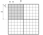
- FIG. 2 is a diagram showing the received power evaluation mesh M1 and the evaluation point side parameter evaluation mesh M2.
- FIG. 2 shows an example in which the size of the reception power evaluation mesh M1 and the size of the evaluation point side parameter evaluation mesh M2 are different.
- the size of the received power evaluation mesh M1 is 20 [m] x 20 [m].
- the size of the evaluation point side parameter evaluation mesh M2 is 100 [m] x 100 [m].
- the base station side parameter evaluation mesh is created for the vicinity of each base station within the evaluation range.
- the size of the base station side parameter evaluation mesh may be larger than, smaller than, or the same as the size of the evaluation point side parameter evaluation mesh M2.
- FIG. 3 is a diagram showing an example of a match list.
- the matching list includes the base station side parameter evaluation mesh, the base station side parameter values obtained from the base station side parameter evaluation mesh, the evaluation point side parameter evaluation mesh, and the evaluation points obtained from the evaluation point side parameter evaluation mesh. This is data that associates side parameter values with received power evaluation points.
- the base station side parameter evaluation mesh is represented by the identification information of the base station side parameter evaluation mesh
- the evaluation point side parameter evaluation mesh is represented by the identification information of the evaluation point side parameter evaluation mesh.
- a received power evaluation point belongs to any received power evaluation mesh. Therefore, the matching list shows the correspondence between the base station side parameter evaluation mesh, the evaluation point side parameter evaluation mesh, and the received power evaluation mesh to which the received power evaluation point belongs.
- the matching list shown in FIG. 3 includes one base station side parameter value and one evaluation point side parameter value, but there may be a plurality of base station side parameters and a plurality of evaluation point side parameters.
- FIG. 4 is a flow diagram showing the processing of the received power estimating device 1.
- an operator or others inputs wireless system information such as the effective radiated power and antenna pattern of the wireless system using the wireless system information input unit 11 (step S1).
- the operator or others inputs base station information including the base station installation location and designations of various setting values used for calculating the received power level using the base station information input unit 12 (step S2). Note that the order of inputs in step S1 and step S2 may be reversed.
- the operator or others inputs selection of an evaluation range through the evaluation range designation unit 13 (step S3).
- the operator may select the evaluation range by specifying the evaluation range on a GUI such as a map displayed on the display included in the received power estimating device 1. This may be done by inputting information in text, or by a combination of these selection methods.
- the received power evaluation mesh creating unit 151 divides the evaluation range selected in step S3 into received power evaluation meshes (step S4).
- the division of the received power evaluation mesh may be specified by the number of meshes, the mesh size, or a combination of these specifying methods.
- the designation of division of the reception power evaluation mesh may be inputted by the evaluation range designation unit 13 or may be stored in the evaluation range division unit 15 in advance.
- the radio wave propagation calculation model selection unit 152 selects a radio wave propagation calculation method (step S5).
- the radio wave propagation calculation model selection unit 152 may select one radio wave propagation calculation model as the radio wave propagation calculation method, or may select a plurality of radio wave propagation calculation models according to the distance between the base station and the received power evaluation point or other conditions. You may select a calculation method that combines calculation models.
- the radio wave propagation calculation model selection unit 152 uses information such as frequency included in the input wireless system information, whether the received power evaluation point is indoors or outdoors, and the visibility between the base station and the received power evaluation point.
- the radio wave propagation calculation model is selected depending on whether or not there is a radio wave propagation calculation model.
- the radio wave propagation calculation model is selected for each combination of an evaluation point or received power evaluation mesh and a base station or base station side parameter evaluation mesh, for example.
- the evaluation range dividing unit 15 After selecting the radio wave propagation calculation method, the evaluation range dividing unit 15 performs processing to derive parameter values according to the selected calculation method. First, the base station-side parameter evaluation mesh creation unit 153 determines whether the base station-side parameters are used in the calculation method selected in step S5 (step S6).
- step S6 When the base station side parameter evaluation mesh creation unit 153 determines that the base station side parameters are used in step S6 (step S6: YES), it performs the process of step S7. That is, the base station side parameter evaluation mesh creation unit 153 creates a base station side parameter evaluation mesh for deriving the value of the base station side parameter in the evaluation range selected in step S3 (step S7).
- the base station side parameter calculation unit 16 reads map data of the area corresponding to the base station side parameter evaluation mesh from the map DB 14 for each base station side parameter evaluation mesh created in step S7, and calculates the map data included in the read map data.
- the base station side parameter values are calculated using the information (step S8).
- step S6 determines in step S6 that the base station side parameters are not used (step S6: NO), or after the process in step S8, the received power estimating device 1 performs step S9. Process. That is, the evaluation point side parameter evaluation mesh creation unit 154 determines whether the evaluation point side parameter is used in the calculation method selected in step S5 (step S9).
- step S9 When the evaluation point side parameter evaluation mesh creation unit 154 determines that the evaluation point side parameter is used in step S9 (step S9: YES), it performs the process of step S10. That is, the evaluation point side parameter evaluation mesh creation unit 154 divides the evaluation range selected in step S3 into evaluation point side parameter evaluation meshes for deriving the values of the evaluation point side parameters (step S10).
- the evaluation point side parameter calculation unit 17 reads the map data of the area corresponding to the evaluation point side parameter evaluation mesh from the map DB 14 for each evaluation point side parameter evaluation mesh divided in step S10, and calculates the map data included in the read map data. The value of the evaluation point side parameter is calculated using the information (step S11).
- the match list generation unit 18 generates a match list (step S12).
- the matching list includes the received power evaluation mesh divided in step S4, the base station parameter evaluation mesh divided in step S7, and the base station parameter values calculated for the base station parameter evaluation mesh in step S8. This is data that associates the evaluation point side parameter evaluation mesh divided in step S9 with the value of the evaluation point side parameter calculated for the evaluation point side parameter evaluation mesh in step S10.
- received power evaluation points belonging to the received power evaluation mesh are set as information on the received power evaluation mesh.
- step S9 If the evaluation point side parameter evaluation mesh creation unit 154 determines in step S9 that the evaluation point side parameter is not used (step S9: NO), or after the process in step S12, the received power calculation unit 19 executes the process in step S13.
- the received power calculation unit 19 calculates the received power for each received power evaluation point using the radio wave propagation calculation method selected in step S5 (step S13).
- the received power calculation unit 19 calculates the value of the base station side parameter calculated for the base station side parameter evaluation mesh associated with the received power evaluation mesh to which the received power evaluation point belongs, and The value of the evaluation point side parameter calculated for the evaluation point side parameter evaluation mesh associated with the received power evaluation mesh to which the received power evaluation point belongs is read from the matching list.
- the received power calculation unit 19 adds the value of the read base station side parameter and the evaluation point side parameter to the radio wave propagation calculation method selected in step S5 for the received power evaluation point or the received power evaluation mesh to which the received power evaluation point belongs. By using the value, the received power level at the received power evaluation point is calculated. Note that when there are multiple base stations, the received power level is calculated for each combination of received power evaluation points and base stations.
- the evaluation result output unit 20 outputs an evaluation result indicating the received power level of each received power evaluation point calculated in step S13 (step S14).
- the base station side parameter evaluation mesh and the evaluation point side parameter evaluation mesh depends on the radio wave propagation calculation model and frequency. These parameters are modeled taking into consideration the influence of topography and terrestrial objects. Therefore, it is necessary to take into account that there is a correlation between the representative point and other points in the mesh in the calculation of the radio wave propagation calculation model used.
- the representative point is the installation position of the base station in the case of the base station side, and is, for example, the center point of the evaluation point side parameter evaluation mesh in the case of the received power evaluation point side.
- the received power Pr is calculated by the following equation (1).
- the propagation loss amount L in the case of outdoor visibility is calculated by the following equation (2).
- the value of d RD is calculated by inputting the value of d k obtained by inputting a value from 0 to 4 for k in the following formula (4) and inputting the value into the above formula (3).
- the value of L dRD is obtained by inputting a value from 0 to 4 for k in the following equation (6) to obtain all L dk values, and then calculating the value within the range of the conditions of the above equation (5). Calculated by inputting the value.
- the average building height h r is the average value of the heights of buildings around the base station. That is, the average building height hr is a base station side parameter.
- FIG. 5 is a diagram showing an example of creating a base station side parameter evaluation mesh when calculating the average building height around the base station.
- the base station side parameter evaluation mesh creation unit 153 creates base station side parameter evaluation meshes M3 and M4 using squares of a predetermined size centered on the positions of the two base stations B1 and B2.
- the base station parameter calculation unit 16 reads map data of the area corresponding to the base station parameter evaluation mesh from the map DB 14.
- the base station side parameter calculation unit 16 calculates the average building height h r based on the height of each building indicated by the building information included in the read map data.
- the road width w is the average value of the road widths around the received power evaluation point. That is, the road width w is an evaluation point side parameter.
- FIG. 6 is a diagram showing an example of creating an evaluation point-side parameter evaluation mesh when calculating the average road width around the reception power evaluation point.
- the evaluation point side parameter evaluation mesh generation unit 154 divides the evaluation range M5 into square meshes of a predetermined size, and creates an evaluation point side parameter evaluation mesh M6.
- the evaluation point side parameter calculation unit 17 reads map data of the area corresponding to the evaluation point side parameter evaluation mesh M6 from the map DB 14.
- the evaluation point side parameter calculation unit 17 calculates the road width w based on the position and road width of the road indicated by the structure information included in the read map data.
- the transmission power P T , transmission antenna gain G T , base station feed line loss L f , reception antenna gain G R , frequency f, and wavelength ⁇ are input in step S1 or step S2.
- the distance d between the base station and the reception power evaluation point is determined by the reception power calculation unit 19, for example, from the installation location of the base station obtained from the base station information and topographical information (latitude, longitude, and altitude) included in the map data. It is calculated using the position of the received power evaluation point obtained.
- the road angle ⁇ is calculated, for example, by the evaluation point side parameter calculation unit 17 using information on the position of the road and the installation location and installation method of the base station obtained from the base station information.
- the information on the position of the road is obtained from the structure information included in the map data of the area corresponding to the evaluation point side parameter evaluation mesh.
- the height h2 of the received power evaluation point is obtained, for example, by the received power calculation unit 19 from topographical information included in the map data.
- the received power estimating device 1 creates a base station side parameter evaluation mesh and/or an evaluation point side parameter evaluation mesh, separately from the received power evaluation mesh. Thereby, regardless of the size of the reception power evaluation mesh, it is possible to create a mesh of an appropriate size for deriving the values of parameters used in radio wave propagation calculations.
- the evaluation point side parameter evaluation mesh creation unit 154 takes 100 [m] on each side from the center of the mesh created for deriving the value of the evaluation point side parameter. It is conceivable to create an evaluation point-side parameter evaluation mesh with a size of [m].
- the received power evaluation mesh, the base station side parameter evaluation mesh, and the evaluation point side parameter evaluation mesh are rectangular in the above description, they may be other than rectangular.
- the mesh size for calculating the received power and the mesh size for calculating the value of the radio wave propagation calculation parameter can be set independently. It is possible to calculate the received power of radio waves at each received power evaluation point with good accuracy regardless of the mesh size of the received power.
- the received power estimating device 1 may be realized by a plurality of computer devices connected to a network.
- each functional unit of the received power estimating device 1 can be implemented by any one of the plurality of computer devices.
- the map DB 14 and other functional units may be implemented by different computer devices.
- the same functional unit may be realized by a plurality of computer devices.
- FIG. 7 is a device configuration diagram showing an example of the hardware configuration of the received power estimating device 1.
- the received power estimating device 1 includes a processor 71 , a storage section 72 , a communication interface 73 , and a user interface 74 .
- the processor 71 is a central processing unit that performs calculations and control.
- the processor 71 is, for example, a CPU (central processing unit) or a GPU (graphics processing unit).
- the processor 71 reads a program from the storage unit 72 and executes it.
- the storage unit 72 further includes a work area when the processor 71 executes various programs.
- the communication interface 73 is communicably connected to other devices.
- the user interface 74 is an input device such as a keyboard, a pointing device (mouse, tablet, etc.), a button, a touch panel, or a display device such as a display. A human operation is input through the user interface 74 .
- At least some of the functions of the received power estimating device 1 described above are realized by the processor 71 reading a program from the storage unit 72 and executing it.
- the program of the received power estimating device 1 may be recorded on a computer-readable recording medium.
- the computer-readable recording medium is, for example, a portable medium such as a flexible disk, magneto-optical disk, ROM, or CD-ROM, or a storage device such as a hard disk built into a computer system.
- the program of the received power estimating device 1 may be transmitted via a telecommunications line.
- the functions of the received power estimating device 1 may be realized using hardware such as an ASIC (Application Specific Integrated Circuit), a PLD (Programmable Logic Device), or an FPGA (Field Programmable Gate Array).
- the map data DB2 may be realized using the storage unit 72.
- the wireless system information input unit 11, the base station information input unit 12, and the evaluation range designation unit 13 may be realized using the user interface 74.
- the received power estimating device includes an evaluation range dividing section, a matching data generating section, and a received power calculating section.
- the evaluation range dividing unit performs processing to divide the evaluation range, which is a geographical range for evaluating received power, into received power evaluation meshes for calculating received power at evaluation points located within the evaluation range, and evaluation point A process of creating a parameter evaluation mesh in the evaluation range for obtaining the values of parameters for radio wave propagation calculation used in calculating the received power in is performed.
- the matching data generation unit generates data indicating the correspondence between the reception power evaluation mesh and the parameter evaluation mesh.
- the matching data generation section corresponds to, for example, the matching list generation section 18 of the embodiment.
- the received power calculation unit performs radio wave propagation calculation using the value of the radio wave propagation calculation parameter obtained based on the information on the topography or features included in the parameter evaluation mesh corresponding to the received power evaluation mesh to which the evaluation point belongs. , calculate the received power at the evaluation point.
- the size of the parameter evaluation mesh is determined by setting a threshold value for the autocorrelation coefficient of fluctuations in radio wave propagation, depending on the frequency of radio waves received at the evaluation point or according to the radio wave propagation calculation model used for radio wave propagation calculation. You may also decide based on this. For example, the size of the parameter evaluation mesh is set so that the autocorrelation coefficient of fluctuations in radio wave propagation is greater than or equal to a threshold value, depending on the frequency of radio waves received at the evaluation point, or depending on the radio wave propagation calculation model used for radio wave propagation calculation. It may be determined as follows.
- the evaluation range dividing unit may select a radio wave propagation calculation model to be used for radio wave propagation calculation according to the distance between the evaluation point and a wireless device that emits radio waves to the evaluation point.
- the evaluation range dividing unit performs processing of dividing the evaluation range into first parameter evaluation meshes for calculating the values of the first radio wave propagation calculation parameters using topography or feature information around the evaluation point, and evaluation.
- a second parameter evaluation mesh for calculating the value of the second radio wave propagation calculation parameter using information on the topography or features around the wireless device that emits radio waves to a point is installed at the installation position of the wireless device in the evaluation range. You may also perform processing to create the area around the .
- the matching data generation unit generates data indicating a correspondence relationship between the reception power evaluation mesh, the first parameter evaluation mesh, and the second parameter evaluation mesh.
- the received power calculation unit calculates the value of the first radio wave propagation calculation parameter calculated based on the information on topography or features included in the first parameter evaluation mesh corresponding to the received power evaluation mesh to which the evaluation point belongs, and the evaluation The evaluation point is determined by radio wave propagation calculation using the value of the second radio wave propagation calculation parameter calculated based on the information of the topography or features included in the second parameter evaluation mesh corresponding to the reception power evaluation mesh to which the point belongs. Calculate the received power at .
- Received power estimation device 11 Radio system information input section 12 Base station information input section 13 Evaluation range specification section 14 Map DB 15 Evaluation range division section 17 Evaluation point side parameter calculation section 18 Matching list generation section 19 Received power calculation section 20 Evaluation result output section 71 Processor 72 Storage section 73 Communication interface 74 User interface 151 Received power evaluation mesh creation section 152 Radio wave propagation calculation Model selection section 153 Base station side parameter evaluation mesh creation section 154 Evaluation point side parameter evaluation mesh creation section
Landscapes
- Engineering & Computer Science (AREA)
- Computer Networks & Wireless Communication (AREA)
- Signal Processing (AREA)
- Monitoring And Testing Of Transmission In General (AREA)
Abstract
This received signal power estimation device comprises an evaluation area division unit, a matching data generation unit, and a received signal power calculation unit. The evaluation area division unit carries out a process for dividing an evaluation area which is a geographic area for which the received signal power is to be evaluated into a received signal power evaluation mesh, and a process for creating, for the evaluation area, a parameter evaluation mesh for calculating the value of a radio wave propagation calculation parameter which is used to calculate the received signal power at an evaluation point. The matching data generation unit generates data which indicates a correspondence between the received signal power evaluation mesh and the parameter evaluation mesh. The received signal power calculation unit calculates a received signal power at an evaluation point by means of the radio wave propagation calculation which uses the value of the radio wave propagation calculation parameter based on topography or geographic feature information included in the parameter evaluation mesh corresponding to the received signal power evaluation mesh to which the evaluation point belongs.
Description
本発明は、受信電力推定装置、受信電力推定方法及びプログラムに関する。
The present invention relates to a received power estimating device, a received power estimating method, and a program.
無線活用が進み、キャリヤが運用する公衆無線システム以外に、利用者が自営で無線システムを構築することが可能な自営無線システムの利用が拡大している。自営無線システムとして、電波免許不要で利用可能なWi-Fi等に加え、電波免許を取得することにより無線システム利用時に干渉による影響が生じないローカル5G等の新たな無線システムの利用拡大が見込まれる。
With the advancement of wireless utilization, in addition to public wireless systems operated by carriers, the use of private wireless systems, which allow users to construct their own wireless systems, is expanding. As a private wireless system, in addition to Wi-Fi, which can be used without a radio license, the use of new wireless systems such as local 5G, which will not be affected by interference when using the wireless system by obtaining a radio license, is expected to expand. .
こうした電波免許が必要な無線システムを利用する場合には、干渉評価を行い、先行利用者に対して干渉による影響を与えないことを証明する必要がある。例えばローカル5Gの場合には、総務省の訓令(参考文献1:インターネット<https://www.soumu.go.jp/main_content/000711787.pdf>)により干渉評価時の電波伝搬計算式が定められている。あるいは、第5世代モバイル推進フォーラム(5GMF:インターネット<https://5gmf.jp/>)の「ローカル5G免許申請支援マニュアル」(参考文献2:インターネット<https://5gmf.jp/case/4484/>)にて、具体的な干渉評価時の電波伝搬計算結果の描画方法等が公開されている。
When using such a wireless system that requires a radio license, it is necessary to conduct an interference assessment and prove that the interference will not have an impact on previous users. For example, in the case of local 5G, the radio wave propagation calculation formula for interference evaluation is determined by the directive of the Ministry of Internal Affairs and Communications (Reference 1: Internet <https://www.soumu.go.jp/main_content/000711787.pdf>). ing. Alternatively, please refer to the "Local 5G License Application Support Manual" (Reference 2: Internet <https://5gmf.jp/case/4484) from the 5th Generation Mobile Promotion Forum (5GMF: Internet <https://5gmf.jp/>) >>) discloses methods for drawing the results of radio wave propagation calculations during specific interference evaluations.
従来は、地図をメッシュに分割し、メッシュの中心、あるいはメッシュ内のいずれかの定められた方法で決定された受信電力評価点(以下、評価点とも記載する)毎に受信電力を計算することで、受信電力レベルの評価を行っていた(例えば、特許文献1、2参照)。
Conventionally, a map is divided into meshes, and the received power is calculated for each received power evaluation point (hereinafter also referred to as evaluation point) determined at the center of the mesh or by any predetermined method within the mesh. The received power level was evaluated (for example, see Patent Documents 1 and 2).
従来技術では、受信電力レベルを評価する際のメッシュサイズと、電波伝搬計算に用いるパラメータの値を算出するためのメッシュサイズとが同一であった。一方で、電波伝搬計算モデルで地形や地物の影響により変動するパラメータ値を導出するためのエリアをどのように定義するかは、個々の電波伝搬計算モデルに依存する。例えば、電波伝搬計算モデルにITU-R P.1411を適用する場合を例にあげる。ITU-R P.1411の電波伝搬計算モデルでは、平均道路幅、平均建物高をパラメータとして用いる。受信電力レベルを評価する際のメッシュサイズを1辺10mとし、当該メッシュ毎に受信電力を求めることを考える。すると、この大きさのメッシュには、パラメータ値を算出する根拠となる道路や建物等が存在しない可能性があるため、平均道路幅及び平均建物高を計算できない場合がある。平均道路幅及び平均建物高が得られないメッシュについては、受信電力を算出できない。
In the prior art, the mesh size used to evaluate the received power level and the mesh size used to calculate the values of parameters used in radio wave propagation calculations were the same. On the other hand, how to define an area for deriving parameter values that vary due to the influence of topography and features in a radio wave propagation calculation model depends on the individual radio wave propagation calculation model. For example, in the radio wave propagation calculation model, ITU-R P. Let us take as an example the case where 1411 is applied. ITU-R P. The radio wave propagation calculation model of 1411 uses average road width and average building height as parameters. Let us consider that the mesh size when evaluating the received power level is 10 m on a side, and that the received power is determined for each mesh. Then, in a mesh of this size, there is a possibility that there are no roads, buildings, etc. that serve as a basis for calculating parameter values, so it may not be possible to calculate the average road width and average building height. Received power cannot be calculated for meshes for which the average road width and average building height cannot be obtained.
上記事情に鑑み、本発明は、受信電力の評価を行う単位となるメッシュのサイズによらず推定の受信電力を算出可能な受信電力推定装置、受信電力推定方法及びプログラムを提供することを目的としている。
In view of the above circumstances, an object of the present invention is to provide a received power estimation device, a received power estimation method, and a program capable of calculating estimated received power regardless of the size of a mesh that is a unit for evaluating received power. There is.
本発明の一態様の受信電力推定装置は、受信電力を評価する地理的な範囲である評価範囲を、前記評価範囲内に位置する評価点における受信電力を計算するための受信電力評価用メッシュに分割する処理と、前記評価点における受信電力の計算に用いられる電波伝搬計算用パラメータの値を得るためのパラメータ評価メッシュを前記評価範囲に作成する処理とを行う評価範囲分割部と、前記受信電力評価用メッシュと前記パラメータ評価メッシュとの対応関係を示すデータを生成する突合データ生成部と、前記評価点が属する前記受信電力評価用メッシュに対応した前記パラメータ評価メッシュに含まれる地形又は地物の情報に基づいて得られた前記電波伝搬計算用パラメータの値を用いた電波伝搬計算により前記評価点における受信電力を計算する受信電力計算部と、を備える。
A received power estimating device according to one aspect of the present invention sets an evaluation range, which is a geographical range for evaluating received power, to a received power evaluation mesh for calculating received power at evaluation points located within the evaluation range. an evaluation range dividing unit that performs a dividing process and a process of creating a parameter evaluation mesh in the evaluation range for obtaining a value of a parameter for radio wave propagation calculation used to calculate the received power at the evaluation point; and the received power a matching data generation unit that generates data indicating a correspondence relationship between an evaluation mesh and the parameter evaluation mesh, and a topography or feature that is included in the parameter evaluation mesh that corresponds to the received power evaluation mesh to which the evaluation point belongs. and a received power calculation unit that calculates the received power at the evaluation point by a radio wave propagation calculation using the value of the radio wave propagation calculation parameter obtained based on the information.
本発明の一態様の受信電力推定方法は、受信電力を評価する地理的な範囲である評価範囲を、前記評価範囲内に位置する評価点における受信電力を計算するための受信電力評価用メッシュに分割するメッシュ分割ステップと、前記評価点における受信電力の計算に用いられる電波伝搬計算用パラメータの値を得るためのパラメータ評価メッシュを前記評価範囲に作成するメッシュ作成ステップと、前記受信電力評価用メッシュと前記パラメータ評価メッシュとの対応関係を示すデータを生成する突合データ生成ステップと、前記評価点が属する前記受信電力評価用メッシュに対応した前記パラメータ評価メッシュに含まれる地形又は地物の情報に基づいて得られた前記電波伝搬計算用パラメータの値を用いた電波伝搬計算により前記評価点における受信電力を計算する受信電力計算ステップと、を有する。
A received power estimation method according to one aspect of the present invention sets an evaluation range, which is a geographical range for evaluating received power, to a received power evaluation mesh for calculating received power at evaluation points located within the evaluation range. a mesh dividing step of dividing the mesh, a mesh creation step of creating a parameter evaluation mesh in the evaluation range for obtaining a value of a parameter for radio wave propagation calculation used to calculate the received power at the evaluation point, and a mesh creation step of the received power evaluation mesh. and a matching data generation step of generating data indicating a correspondence relationship between the parameter evaluation mesh and the parameter evaluation mesh, based on information on topography or features included in the parameter evaluation mesh corresponding to the received power evaluation mesh to which the evaluation point belongs. and a received power calculation step of calculating the received power at the evaluation point by a radio wave propagation calculation using the value of the radio wave propagation calculation parameter obtained.
本発明の一態様は、コンピュータを、上述した受信電力推定装置として機能させるためのプログラムである。
One aspect of the present invention is a program for causing a computer to function as the above-mentioned received power estimating device.
本発明により、受信電力の評価を行う単位となるメッシュのサイズによらず推定の受信電力を算出することが可能となる。
According to the present invention, it is possible to calculate estimated received power regardless of the size of the mesh that is the unit for evaluating received power.
以下、図面を参照しながら本発明の実施形態を詳細に説明する。本実施形態の受信電力推定装置は、受信電力評価点における受信電力を評価する地理的な領域の単位となるメッシュのサイズと、電波伝搬計算用パラメータの値を算出するためのメッシュのサイズとを個々に導出する。さらには、本実施形態の受信電力推定装置は、電波伝搬計算用パラメータの値を算出するためのメッシュのサイズを、周波数に応じてあるいは受信電力の計算に用いる電波伝搬計算モデルに応じて、算出される受信電力の変動の自己相関係数の閾値を定めて判定することにより決定する。これにより、受信電力を評価するためのメッシュのサイズによらず、電波伝搬計算用パラメータの算出に適切なサイズのメッシュの単位でパラメータ値を導出可能とする。
Hereinafter, embodiments of the present invention will be described in detail with reference to the drawings. The received power estimating device of this embodiment determines the size of a mesh that is a unit of a geographical area for evaluating received power at a received power evaluation point, and the size of a mesh for calculating the value of a parameter for radio wave propagation calculation. Derived individually. Furthermore, the received power estimating device of this embodiment calculates the mesh size for calculating the value of the parameter for radio wave propagation calculation according to the frequency or according to the radio wave propagation calculation model used for calculating the received power. This is determined by determining a threshold value for the autocorrelation coefficient of fluctuations in received power. This makes it possible to derive parameter values in mesh units of appropriate size for calculating parameters for radio wave propagation calculation, regardless of the size of the mesh for evaluating received power.
図1は、本発明の実施形態における受信電力推定装置1の構成を示す機能ブロック図である。受信電力推定装置1は、例えば、コンピュータ装置で実現することができる。図1では、本実施形態と関係する機能ブロックのみを抽出して示してある。受信電力推定装置1は、無線システム情報入力部11と、基地局情報入力部12と、評価範囲指定部13と、地図データベース(DB)14と、評価範囲分割部15と、基地局側パラメータ計算部16と、評価点側パラメータ計算部17と、突合リスト生成部18と、受信電力計算部19と、評価結果出力部20とを備える。
FIG. 1 is a functional block diagram showing the configuration of a received power estimating device 1 in an embodiment of the present invention. The received power estimating device 1 can be realized by, for example, a computer device. In FIG. 1, only functional blocks related to this embodiment are extracted and shown. The received power estimation device 1 includes a radio system information input section 11, a base station information input section 12, an evaluation range specification section 13, a map database (DB) 14, an evaluation range division section 15, and a base station side parameter calculation unit. section 16 , evaluation point side parameter calculation section 17 , matching list generation section 18 , received power calculation section 19 , and evaluation result output section 20 .
無線システム情報入力部11、基地局情報入力部12及び評価範囲指定部13は、基地局から放射された電波の受信電力を計算する前提となる条件を入力する入力部である。入力部は、例えば、キーボード、マウス、タッチパネル、ボタンやキーなどによりユーザが入力した情報を受信する。あるいは、入力部は、ネットワークを介して接続される他のコンピュータ装置から情報を受信したり、コンピュータ読み取り可能な記録媒体から情報を読み出したりするものでもよい。
The wireless system information input unit 11, the base station information input unit 12, and the evaluation range designation unit 13 are input units that input conditions that are a prerequisite for calculating the received power of radio waves radiated from a base station. The input unit receives information input by a user using, for example, a keyboard, a mouse, a touch panel, buttons, or keys. Alternatively, the input unit may receive information from another computer device connected via a network or read information from a computer-readable recording medium.
無線システム情報入力部11は、無線システムの実効輻射電力やアンテナパターン等の無線システムに関する情報を入力する。実効輻射電力として、送信電力、アンテナ利得、給電線損失等が入力されてもよい。
The wireless system information input unit 11 inputs information regarding the wireless system, such as the effective radiated power and antenna pattern of the wireless system. Transmission power, antenna gain, feed line loss, etc. may be input as the effective radiated power.
基地局情報入力部12は、基地局情報を入力する。基地局情報は、基地局の設置場所、設置環境及び設置情報など、基地局に関する情報を含む。設置場所として、緯度、経度、及び、高さ等が入力されてもよい。高さは、地上高でもよく、標高でもよい。また、設置環境として、屋内あるいは屋外等が入力され、屋内の場合には、建物侵入損等がさらに入力される。設置方法として、基地局が有するアンテナの東西南北の方向及び仰俯角等が入力される。
The base station information input unit 12 inputs base station information. The base station information includes information regarding the base station, such as the installation location, installation environment, and installation information of the base station. Latitude, longitude, height, etc. may be input as the installation location. The height may be ground clearance or altitude. Further, as the installation environment, indoors or outdoors, etc. are input, and in the case of indoors, building penetration loss, etc. are further input. As the installation method, the north, south, east, west, and elevation angles of the antenna of the base station are input.
評価範囲指定部13は、操作者の操作あるいはその他の条件に則って、地図上に評価範囲を指定する。
The evaluation range specifying unit 13 specifies an evaluation range on the map according to the operator's operation or other conditions.
地図DB14は、地図データを記憶する記憶部である。地図データは、地形情報、建物情報、構造物情報、土地利用情報等の情報を含む。地形情報は、緯度、経度及び標高等の情報である。建物情報、構造物情報及び土地利用情報は、地形情報と紐づけられる。建物情報及び構造物情報は、地物の情報である。建物情報は、建物の外郭及び高さ等の情報である。構造物情報は、道路の位置及び道路幅等の情報である。土地利用情報は、建物用地・海面・湖面・農地・森林等の情報である。
The map DB 14 is a storage unit that stores map data. The map data includes information such as topographic information, building information, structure information, and land use information. The topographical information is information such as latitude, longitude, and altitude. Building information, structure information, and land use information are linked to topographic information. The building information and structure information are information on local features. The building information is information such as the outline and height of the building. The structure information is information such as the position of the road and the width of the road. Land use information includes information on building sites, sea level, lake level, farmland, forests, etc.
評価範囲分割部15は、評価範囲指定部13により指定された地理的な評価範囲を分割して、受信電力評価用メッシュ、基地局側パラメータ評価メッシュ、及び、評価点側パラメータ評価メッシュを作成する機能を有する。評価範囲分割部15は、受信電力評価用メッシュ作成部151と、電波伝搬計算モデル選択部152と、基地局側パラメータ評価メッシュ作成部153と、評価点側パラメータ評価メッシュ作成部154とを有する。
The evaluation range dividing unit 15 divides the geographical evaluation range specified by the evaluation range specifying unit 13 to create a reception power evaluation mesh, a base station side parameter evaluation mesh, and an evaluation point side parameter evaluation mesh. Has a function. The evaluation range division section 15 includes a reception power evaluation mesh creation section 151, a radio wave propagation calculation model selection section 152, a base station side parameter evaluation mesh creation section 153, and an evaluation point side parameter evaluation mesh creation section 154.
受信電力評価用メッシュ作成部151は、操作者による入力あるいはその他の条件に則って評価範囲を分割することにより、受信電力評価用メッシュを作成する機能を有する。受信電力評価用メッシュは、受信電力評価点における受信電力を評価する単位である。電波伝搬計算モデル選択部152は、受信電力評価点における受信電力の計算に用いる電波伝搬計算モデルを選択する機能を有する。例えば、電波伝搬計算モデルにより受信電力レベルが算出される。
The reception power evaluation mesh creation unit 151 has a function of creating a reception power evaluation mesh by dividing the evaluation range according to input by the operator or other conditions. The reception power evaluation mesh is a unit for evaluating reception power at a reception power evaluation point. The radio wave propagation calculation model selection unit 152 has a function of selecting a radio wave propagation calculation model to be used for calculating the received power at the received power evaluation point. For example, the received power level is calculated using a radio wave propagation calculation model.
基地局側パラメータ評価メッシュ作成部153は、電波伝搬計算モデルに基地局側パラメータが含まれる場合に、評価範囲の基地局周辺に対して基地局側パラメータ評価メッシュを作成する機能を有する。基地局側パラメータ評価メッシュは、基地局側パラメータの値を算出するための領域である。基地局側パラメータは、基地局の周辺の情報によって値が変動する電波伝搬計算用パラメータである。
The base station side parameter evaluation mesh creation unit 153 has a function of creating a base station side parameter evaluation mesh around the base station in the evaluation range when the radio wave propagation calculation model includes base station side parameters. The base station parameter evaluation mesh is an area for calculating values of base station parameters. The base station side parameters are radio wave propagation calculation parameters whose values vary depending on information around the base station.
評価点側パラメータ評価メッシュ作成部154は、電波伝搬計算モデルに評価点側パラメータが含まれる場合に、評価範囲を分割して評価点側パラメータ評価メッシュを作成する機能を有する。評価点側パラメータ評価メッシュは、評価点側パラメータの値を算出するための領域である。評価点側パラメータは、受信電力評価点の周辺の情報によって値が変動する電波伝搬計算用パラメータである。
The evaluation point side parameter evaluation mesh creation unit 154 has a function of dividing the evaluation range and creating an evaluation point side parameter evaluation mesh when the radio wave propagation calculation model includes evaluation point side parameters. The evaluation point side parameter evaluation mesh is an area for calculating the value of the evaluation point side parameter. The evaluation point side parameter is a radio wave propagation calculation parameter whose value varies depending on information around the received power evaluation point.
基地局側パラメータ計算部16は、基地局側パラメータの値を導出する機能を有する。すなわち、基地局側パラメータ計算部16は、電波伝搬計算モデルに用いられる基地局側パラメータの中に、地形や地物の情報など地図データに基づき計算することが必要な基地局側パラメータがあるか否かを判断する。基地局側パラメータ計算部16は、そのような基地局側パラメータがあると判断した場合、基地局側パラメータ評価メッシュ作成部153が作成した基地局側パラメータ評価メッシュに基づき、その基地局側パラメータの値を計算するための情報を地図DB14から取得する。基地局側パラメータ計算部16は、取得した情報を用いて基地局側パラメータの値を導出する。基地局側パラメータの値の導出には、基地局情報など地図DB14から取得されない情報をさらに用いてもよい。
The base station side parameter calculation unit 16 has a function of deriving the value of the base station side parameter. That is, the base station side parameter calculation unit 16 determines whether among the base station side parameters used in the radio wave propagation calculation model, there are base station side parameters that need to be calculated based on map data such as topography and feature information. Decide whether or not. When the base station side parameter calculation unit 16 determines that there is such a base station side parameter, the base station side parameter calculation unit 16 calculates the base station side parameter based on the base station side parameter evaluation mesh created by the base station side parameter evaluation mesh creation unit 153. Information for calculating the value is acquired from the map DB 14. The base station side parameter calculation unit 16 derives the value of the base station side parameter using the acquired information. Information that is not acquired from the map DB 14, such as base station information, may be further used to derive the value of the base station side parameter.
評価点側パラメータ計算部17は、評価点側パラメータの値を導出する機能を有する。すなわち、評価点側パラメータ計算部17は、電波伝搬計算モデルに用いられる評価点側パラメータの中に、地形や地物の情報など地図データに基づき計算することが必要な評価点側パラメータがあるか否かを判断する。評価点側パラメータ計算部17は、そのような評価点側パラメータがあると判断した場合、評価点側パラメータ評価メッシュ作成部154が作成した評価点側パラメータ評価メッシュに基づき、その評価点側パラメータの値を計算するための情報を地図DB14から取得する。評価点側パラメータ計算部17は、取得した情報を用いて評価点側パラメータの値を導出する。評価点側パラメータの値の導出には、地図DB14から取得されない情報がさらに用いられてもよい。
The evaluation point side parameter calculation unit 17 has a function of deriving the value of the evaluation point side parameter. That is, the evaluation point side parameter calculation unit 17 determines whether there are evaluation point side parameters that need to be calculated based on map data such as topography and feature information among the evaluation point side parameters used in the radio wave propagation calculation model. Decide whether or not. When the evaluation point side parameter calculation unit 17 determines that there is such an evaluation point side parameter, the evaluation point side parameter calculation unit 17 calculates the evaluation point side parameter based on the evaluation point side parameter evaluation mesh created by the evaluation point side parameter evaluation mesh creation unit 154. Information for calculating the value is acquired from the map DB 14. The evaluation point side parameter calculation unit 17 derives the value of the evaluation point side parameter using the acquired information. Information that is not acquired from the map DB 14 may be further used to derive the value of the evaluation point side parameter.
突合リスト生成部18は、評価範囲分割部15が作成した受信電力評価用メッシュ、基地局側パラメータ評価メッシュ、及び、評価点側パラメータ評価メッシュの3つを突合する突合リストを作成する機能を有する。突合リスト生成部18は、突合リストに、電波伝搬計算モデルに用いられる各々の基地局側パラメータ及び評価点側パラメータの値をさらに格納する。
The matching list generation unit 18 has a function of creating a matching list that matches the received power evaluation mesh, the base station side parameter evaluation mesh, and the evaluation point side parameter evaluation mesh created by the evaluation range division unit 15. . The matching list generation unit 18 further stores, in the matching list, the values of each base station side parameter and evaluation point side parameter used in the radio wave propagation calculation model.
受信電力計算部19は、無線システム情報、基地局情報、基地局側パラメータ、及び、評価点側パラメータの少なくとも一部を用いて、電波伝搬計算モデルに則って受信電力評価点毎の受信電力を計算する機能を有する。評価結果出力部20は、受信電力計算部19の計算結果を任意の出力方法を用いて出力する機能を有する。例えば、評価結果出力部20は、各受信電力評価用メッシュにおける受信電力を、GUI(グラフィック・ユーザ・インタフェース)により地図上に表示してもよく、テキスト情報により出力してもよい。
The received power calculation unit 19 calculates the received power for each received power evaluation point according to the radio wave propagation calculation model using at least part of the wireless system information, base station information, base station side parameters, and evaluation point side parameters. It has the ability to calculate. The evaluation result output section 20 has a function of outputting the calculation result of the received power calculation section 19 using an arbitrary output method. For example, the evaluation result output unit 20 may display the received power in each received power evaluation mesh on a map using a GUI (graphic user interface), or may output it as text information.
図2は、受信電力評価用メッシュM1と、評価点側パラメータ評価メッシュM2とを示す図である。図2は、受信電力評価用メッシュM1のサイズと、評価点側パラメータ評価メッシュM2のサイズとが異なっている例を示す。この例では、受信電力評価用メッシュM1のサイズは、20[m]×20[m]である。一方で、評価点側パラメータ評価メッシュM2のサイズは100[m]×100[m]である。なお、基地局側パラメータ評価メッシュは、評価範囲内の各基地局の周辺に対して作成される。基地局側パラメータ評価メッシュのサイズは、評価点側パラメータ評価メッシュM2のサイズより大きくてもよく、小さくてもよく、同じででもよい。
FIG. 2 is a diagram showing the received power evaluation mesh M1 and the evaluation point side parameter evaluation mesh M2. FIG. 2 shows an example in which the size of the reception power evaluation mesh M1 and the size of the evaluation point side parameter evaluation mesh M2 are different. In this example, the size of the received power evaluation mesh M1 is 20 [m] x 20 [m]. On the other hand, the size of the evaluation point side parameter evaluation mesh M2 is 100 [m] x 100 [m]. Note that the base station side parameter evaluation mesh is created for the vicinity of each base station within the evaluation range. The size of the base station side parameter evaluation mesh may be larger than, smaller than, or the same as the size of the evaluation point side parameter evaluation mesh M2.
図3は、突合リストの例を示す図である。突合リストは、基地局側パラメータ評価メッシュと、基地局側パラメータ評価メッシュから得られた基地局側パラメータの値と、評価点側パラメータ評価メッシュと、評価点側パラメータ評価メッシュから得られた評価点側パラメータの値と、受信電力評価点とを対応付けたデータである。基地局側パラメータ評価メッシュは、基地局側パラメータ評価メッシュの識別情報により表され、評価点側パラメータ評価メッシュは、評価点側パラメータ評価メッシュの識別情報により表される。受信電力評価点は、いずれかの受信電力評価用メッシュに属する。そのため、突合リストは、基地局側パラメータ評価メッシュと、評価点側パラメータ評価メッシュと、受信電力評価点が属す受信電力評価用メッシュとの対応付けを示す。図3に示す突合リストには、基地局側パラメータの値、及び、評価点側パラメータの値が一つずつ含まれているが、基地局側パラメータ及び評価点側パラメータはそれぞれ複数でもよい。
FIG. 3 is a diagram showing an example of a match list. The matching list includes the base station side parameter evaluation mesh, the base station side parameter values obtained from the base station side parameter evaluation mesh, the evaluation point side parameter evaluation mesh, and the evaluation points obtained from the evaluation point side parameter evaluation mesh. This is data that associates side parameter values with received power evaluation points. The base station side parameter evaluation mesh is represented by the identification information of the base station side parameter evaluation mesh, and the evaluation point side parameter evaluation mesh is represented by the identification information of the evaluation point side parameter evaluation mesh. A received power evaluation point belongs to any received power evaluation mesh. Therefore, the matching list shows the correspondence between the base station side parameter evaluation mesh, the evaluation point side parameter evaluation mesh, and the received power evaluation mesh to which the received power evaluation point belongs. The matching list shown in FIG. 3 includes one base station side parameter value and one evaluation point side parameter value, but there may be a plurality of base station side parameters and a plurality of evaluation point side parameters.
図4は、受信電力推定装置1の処理を示すフロー図である。まず、操作者あるいはその他は、無線システム情報入力部11により、無線システムの実効輻射電力やアンテナパターン等の無線システム情報を入力する(ステップS1)。続いて、操作者あるいはその他は、基地局情報入力部12により、基地局設置位置を含む基地局情報と、受信電力レベルの計算に用いる各種の設定値の指定とを入力する(ステップS2)。なお、ステップS1及びステップS2における入力の順序は入れ替わってもよい。
FIG. 4 is a flow diagram showing the processing of the received power estimating device 1. First, an operator or others inputs wireless system information such as the effective radiated power and antenna pattern of the wireless system using the wireless system information input unit 11 (step S1). Subsequently, the operator or others inputs base station information including the base station installation location and designations of various setting values used for calculating the received power level using the base station information input unit 12 (step S2). Note that the order of inputs in step S1 and step S2 may be reversed.
次に、操作者あるいはその他は、評価範囲指定部13により評価範囲の選択を入力する(ステップS3)。例えば、操作者は、評価範囲の選択を、受信電力推定装置1が備えるディスプレイに表示される地図等のGUI上で評価範囲を指定することにより行ってもよく、評価範囲の緯度及び経度等の情報をテキストで入力することにより行ってもよく、これらの選択方法を組み合わせることにより行ってもよい。
Next, the operator or others inputs selection of an evaluation range through the evaluation range designation unit 13 (step S3). For example, the operator may select the evaluation range by specifying the evaluation range on a GUI such as a map displayed on the display included in the received power estimating device 1. This may be done by inputting information in text, or by a combination of these selection methods.
次に、受信電力評価用メッシュ作成部151は、ステップS3において選択された評価範囲を、受信電力評価用メッシュに分割する(ステップS4)。例えば、受信電力評価用メッシュの分割は、メッシュ数で指定されてもよいし、メッシュサイズで指定されてもよいし、これらの指定方法を組み合わせて指定されてもよい。また、受信電力評価用メッシュの分割の指定は、評価範囲指定部13により入力されてもよく、予め評価範囲分割部15に記憶されていてもよい。
Next, the received power evaluation mesh creating unit 151 divides the evaluation range selected in step S3 into received power evaluation meshes (step S4). For example, the division of the received power evaluation mesh may be specified by the number of meshes, the mesh size, or a combination of these specifying methods. Further, the designation of division of the reception power evaluation mesh may be inputted by the evaluation range designation unit 13 or may be stored in the evaluation range division unit 15 in advance.
次に、電波伝搬計算モデル選択部152は、電波伝搬計算方法を選択する(ステップS5)。電波伝搬計算モデル選択部152は、電波伝搬計算方法として、一つの電波伝搬計算モデルを選択してもよいし、基地局と受信電力評価点との距離あるいはその他の条件に応じて複数の電波伝搬計算モデルを組み合わせる計算方法を選択してもよい。例えば、電波伝搬計算モデル選択部152は、入力された無線システム情報に含まれる周波数等の情報や、受信電力評価点が屋内であるか屋外であるか、基地局と受信電力評価点とに見通しがあるか否か等に応じて、電波伝搬計算モデルを選択する。電波伝搬計算モデルは、例えば、評価点又は受信電力評価用メッシュと、基地局又は基地局側パラメータ評価メッシュとの組み合わせごとに選択される。
Next, the radio wave propagation calculation model selection unit 152 selects a radio wave propagation calculation method (step S5). The radio wave propagation calculation model selection unit 152 may select one radio wave propagation calculation model as the radio wave propagation calculation method, or may select a plurality of radio wave propagation calculation models according to the distance between the base station and the received power evaluation point or other conditions. You may select a calculation method that combines calculation models. For example, the radio wave propagation calculation model selection unit 152 uses information such as frequency included in the input wireless system information, whether the received power evaluation point is indoors or outdoors, and the visibility between the base station and the received power evaluation point. The radio wave propagation calculation model is selected depending on whether or not there is a radio wave propagation calculation model. The radio wave propagation calculation model is selected for each combination of an evaluation point or received power evaluation mesh and a base station or base station side parameter evaluation mesh, for example.
参考として、第5世代モバイル推進フォーラム(5GMF)の「ローカル5G免許申請支援マニュアル」(参考文献2)に記載の電波伝搬計算モデルのうち、28GHz帯に係るITU-R P.1411の一部である「屋外で見通し外の場合」を後述する。後述の通り、ローカル5Gというシステムの場合にも、周波数や、屋内、屋外あるいは見通しの有無等の環境に応じて、いずれかの電波伝搬計算モデルを選択する場合と、複数の電波伝搬モデルを組み合わせて評価を行う場合とがある。
For reference, among the radio wave propagation calculation models described in the "Local 5G License Application Support Manual" (Reference 2) of the 5th Generation Mobile Promotion Forum (5GMF), ITU-R P. 1411 will be described later. As explained later, even in the case of local 5G systems, there are cases in which one radio wave propagation calculation model is selected depending on the frequency and the environment such as indoors, outdoors, or visibility, and there are cases in which multiple radio wave propagation models are combined. There are cases where evaluation is performed based on
電波伝搬計算方法の選択後、評価範囲分割部15は、選択された計算方法に応じたパラメータの値を導出するための処理を行う。まず、基地局側パラメータ評価メッシュ作成部153は、ステップS5において選択された計算方法において基地局側パラメータが使用されるかどうかを判断する(ステップS6)。
After selecting the radio wave propagation calculation method, the evaluation range dividing unit 15 performs processing to derive parameter values according to the selected calculation method. First, the base station-side parameter evaluation mesh creation unit 153 determines whether the base station-side parameters are used in the calculation method selected in step S5 (step S6).
基地局側パラメータ評価メッシュ作成部153は、ステップS6において基地局側パラメータが使用されると判断した場合(ステップS6:YES)、ステップS7の処理を行う。すなわち、基地局側パラメータ評価メッシュ作成部153は、ステップS3において選択された評価範囲に、基地局側パラメータの値を導出するための基地局側パラメータ評価メッシュを作成する(ステップS7)。基地局側パラメータ計算部16は、ステップS7において作成された基地局側パラメータ評価メッシュごとに、地図DB14から基地局側パラメータ評価メッシュに対応した領域の地図データを読み出し、読み出した地図データに含まれる情報を用いて基地局側パラメータの値を計算する(ステップS8)。
When the base station side parameter evaluation mesh creation unit 153 determines that the base station side parameters are used in step S6 (step S6: YES), it performs the process of step S7. That is, the base station side parameter evaluation mesh creation unit 153 creates a base station side parameter evaluation mesh for deriving the value of the base station side parameter in the evaluation range selected in step S3 (step S7). The base station side parameter calculation unit 16 reads map data of the area corresponding to the base station side parameter evaluation mesh from the map DB 14 for each base station side parameter evaluation mesh created in step S7, and calculates the map data included in the read map data. The base station side parameter values are calculated using the information (step S8).
一方、基地局側パラメータ評価メッシュ作成部153がステップS6において基地局側パラメータは使用されないと判断した場合(ステップS6:NO)、又は、ステップS8の処理の後、受信電力推定装置1はステップS9の処理を行う。すなわち、評価点側パラメータ評価メッシュ作成部154は、ステップS5において選択された計算方法において評価点側パラメータが使用されるかどうかを判断する(ステップS9)。
On the other hand, if the base station side parameter evaluation mesh creation unit 153 determines in step S6 that the base station side parameters are not used (step S6: NO), or after the process in step S8, the received power estimating device 1 performs step S9. Process. That is, the evaluation point side parameter evaluation mesh creation unit 154 determines whether the evaluation point side parameter is used in the calculation method selected in step S5 (step S9).
評価点側パラメータ評価メッシュ作成部154は、ステップS9において評価点側パラメータが使用されると判断した場合(ステップS9:YES)、ステップS10の処理を行う。すなわち、評価点側パラメータ評価メッシュ作成部154は、ステップS3において選択された評価範囲を、評価点側パラメータの値を導出するための評価点側パラメータ評価メッシュに分割する(ステップS10)。評価点側パラメータ計算部17は、ステップS10において分割された評価点側パラメータ評価メッシュごとに、地図DB14から評価点側パラメータ評価メッシュに対応した領域の地図データを読み出し、読み出した地図データに含まれる情報を用いて評価点側パラメータの値を計算する(ステップS11)。
When the evaluation point side parameter evaluation mesh creation unit 154 determines that the evaluation point side parameter is used in step S9 (step S9: YES), it performs the process of step S10. That is, the evaluation point side parameter evaluation mesh creation unit 154 divides the evaluation range selected in step S3 into evaluation point side parameter evaluation meshes for deriving the values of the evaluation point side parameters (step S10). The evaluation point side parameter calculation unit 17 reads the map data of the area corresponding to the evaluation point side parameter evaluation mesh from the map DB 14 for each evaluation point side parameter evaluation mesh divided in step S10, and calculates the map data included in the read map data. The value of the evaluation point side parameter is calculated using the information (step S11).
突合リスト生成部18は、突合リストを生成する(ステップS12)。突合リストは、ステップS4において分割された受信電力評価用メッシュと、ステップS7において分割された基地局側パラメータ評価メッシュと、ステップS8において基地局側パラメータ評価メッシュについて算出された基地局側パラメータの値と、ステップS9において分割された評価点側パラメータ評価メッシュと、ステップS10において評価点側パラメータ評価メッシュについて算出された評価点側パラメータの値とを対応付けたデータである。なお、図3に示す突合リストの場合、受信電力評価用メッシュの情報として、受信電力評価用メッシュに属する受信電力評価点が設定される。
The match list generation unit 18 generates a match list (step S12). The matching list includes the received power evaluation mesh divided in step S4, the base station parameter evaluation mesh divided in step S7, and the base station parameter values calculated for the base station parameter evaluation mesh in step S8. This is data that associates the evaluation point side parameter evaluation mesh divided in step S9 with the value of the evaluation point side parameter calculated for the evaluation point side parameter evaluation mesh in step S10. In the case of the matching list shown in FIG. 3, received power evaluation points belonging to the received power evaluation mesh are set as information on the received power evaluation mesh.
評価点側パラメータ評価メッシュ作成部154が、ステップS9において評価点側パラメータは使用されないと判定した場合(ステップS9:NO)、又は、ステップS12の処理の後、受信電力計算部19は、ステップS13の処理を行う。すなわち、受信電力計算部19は、ステップS5において選択された電波伝搬計算方法を用いて、受信電力評価点毎の受信電力を計算する(ステップS13)。突合リストが生成されている場合、受信電力計算部19は、受信電力評価点が属する受信電力評価用メッシュに対応付けられた基地局側パラメータ評価メッシュについて算出された基地局側パラメータの値と、受信電力評価点が属する受信電力評価用メッシュに対応付けられた評価点側パラメータ評価メッシュについて算出された評価点側パラメータの値とを突合リストから読み出す。受信電力計算部19は、受信電力評価点又は受信電力評価点が属する受信電力評価用メッシュについてステップS5において選択された電波伝搬計算方法に、読み出した基地局側パラメータの値及び評価点側パラメータの値を用いることにより、受信電力評価点における受信電力レベルを算出する。なお、基地局が複数ある場合、受信電力評価点と基地局との組み合わせ毎に受信電力レベルを計算する。評価結果出力部20は、ステップS13において算出された各受信電力評価点の受信電力レベルを示す評価結果を出力する(ステップS14)。
If the evaluation point side parameter evaluation mesh creation unit 154 determines in step S9 that the evaluation point side parameter is not used (step S9: NO), or after the process in step S12, the received power calculation unit 19 executes the process in step S13. Process. That is, the received power calculation unit 19 calculates the received power for each received power evaluation point using the radio wave propagation calculation method selected in step S5 (step S13). When the matching list has been generated, the received power calculation unit 19 calculates the value of the base station side parameter calculated for the base station side parameter evaluation mesh associated with the received power evaluation mesh to which the received power evaluation point belongs, and The value of the evaluation point side parameter calculated for the evaluation point side parameter evaluation mesh associated with the received power evaluation mesh to which the received power evaluation point belongs is read from the matching list. The received power calculation unit 19 adds the value of the read base station side parameter and the evaluation point side parameter to the radio wave propagation calculation method selected in step S5 for the received power evaluation point or the received power evaluation mesh to which the received power evaluation point belongs. By using the value, the received power level at the received power evaluation point is calculated. Note that when there are multiple base stations, the received power level is calculated for each combination of received power evaluation points and base stations. The evaluation result output unit 20 outputs an evaluation result indicating the received power level of each received power evaluation point calculated in step S13 (step S14).
基地局側パラメータ評価メッシュや評価点側パラメータ評価メッシュを、どのようなサイズで作成することが望ましいかは、電波伝搬計算モデルや周波数に依存する。これらのパラメータは、地形や地物の影響等を考慮してモデル化されている。そのため、メッシュ内の代表点及び他の点との間で、使用される電波伝搬計算モデルの計算において相関があること等を考慮することが必要になる。なお、代表点は、基地局側の場合は基地局の設置位置であり、受信電力評価点側の場合は評価点側パラメータ評価メッシュの例えば中心点などである。
What size it is desirable to create the base station side parameter evaluation mesh and the evaluation point side parameter evaluation mesh depends on the radio wave propagation calculation model and frequency. These parameters are modeled taking into consideration the influence of topography and terrestrial objects. Therefore, it is necessary to take into account that there is a correlation between the representative point and other points in the mesh in the calculation of the radio wave propagation calculation model used. Note that the representative point is the installation position of the base station in the case of the base station side, and is, for example, the center point of the evaluation point side parameter evaluation mesh in the case of the received power evaluation point side.
基地局側パラメータや評価点側パラメータを電波伝搬計算方法に適用する場合の例の詳細を、実際の電波伝搬計算モデルに基づき説明する。ここでは、ローカル5G免許申請支援マニュアルに記載のITU-R P.1411の電波伝搬モデルを説明する。受信電力Prは、以下の式(1)により算出される。
Details of an example of applying base station side parameters and evaluation point side parameters to the radio wave propagation calculation method will be explained based on an actual radio wave propagation calculation model. Here, we will introduce the ITU-R P.ITU-R described in the local 5G license application support manual. The radio wave propagation model of 1411 will be explained below. The received power Pr is calculated by the following equation (1).

屋外で見通しの場合の伝搬損失量Lは、以下の式(2)により算出される。
The propagation loss amount L in the case of outdoor visibility is calculated by the following equation (2).

上記式(2)におけるdRDは、以下の式(3)により算出される。
d RD in the above formula (2) is calculated by the following formula (3).

dRDの値は、以下の式(4)のkに0から4までの値を入力して求めたdkの値を、上記の式(3)に値を入力して算出される。
The value of d RD is calculated by inputting the value of d k obtained by inputting a value from 0 to 4 for k in the following formula (4) and inputting the value into the above formula (3).

また、式(2)におけるLdRDの値は、以下の式(5)により算出される。
Furthermore, the value of L dRD in equation (2) is calculated using equation (5) below.

また、LdRDの値は、以下の式(6)のkに0から4までの値を入力して全てのLdkの値を求めた後、上記の式(5)の条件の範囲内の値を入力して算出される。
In addition, the value of L dRD is obtained by inputting a value from 0 to 4 for k in the following equation (6) to obtain all L dk values, and then calculating the value within the range of the conditions of the above equation (5). Calculated by inputting the value.

上記の式において、平均建物高hrは基地局周辺の建物の高さの平均値である。すなわち、平均建物高hrは、基地局側パラメータである。図5は、基地局周辺の平均建物高を求める場合の基地局側パラメータ評価メッシュの作成例を示す図である。図5では、基地局側パラメータ評価メッシュ作成部153は、2台の基地局B1、B2の位置を中心とした所定のサイズの正方形により基地局側パラメータ評価メッシュM3、M4を作成している。基地局側パラメータ計算部16は、基地局側パラメータ評価メッシュに対応した領域の地図データを地図DB14から読み出す。基地局側パラメータ計算部16は、読み出した地図データに含まれる建物情報が示す各建物の高さに基づいて平均建物高hrを算出する。
In the above equation, the average building height h r is the average value of the heights of buildings around the base station. That is, the average building height hr is a base station side parameter. FIG. 5 is a diagram showing an example of creating a base station side parameter evaluation mesh when calculating the average building height around the base station. In FIG. 5, the base station side parameter evaluation mesh creation unit 153 creates base station side parameter evaluation meshes M3 and M4 using squares of a predetermined size centered on the positions of the two base stations B1 and B2. The base station parameter calculation unit 16 reads map data of the area corresponding to the base station parameter evaluation mesh from the map DB 14. The base station side parameter calculation unit 16 calculates the average building height h r based on the height of each building indicated by the building information included in the read map data.
また、同様に上記の式において道路幅wは、受信電力評価点周辺の道路幅の平均値である。すなわち、道路幅wは、評価点側パラメータである。図6は、受信電力評価点周辺の平均道路幅を求める場合の評価点側パラメータ評価メッシュの作成例を示す図である。図6では、評価点側パラメータ評価メッシュ作成部154は、評価範囲M5を分割して所定のサイズの正方形ごとのメッシュに分割し、評価点側パラメータ評価メッシュM6を作成している。評価点側パラメータ計算部17は、評価点側パラメータ評価メッシュM6に対応した領域の地図データを地図DB14から読み出す。評価点側パラメータ計算部17は、読み出した地図データに含まれる構造物情報が示す道路の位置及び道路幅に基づいて道路幅wを算出する。
Similarly, in the above equation, the road width w is the average value of the road widths around the received power evaluation point. That is, the road width w is an evaluation point side parameter. FIG. 6 is a diagram showing an example of creating an evaluation point-side parameter evaluation mesh when calculating the average road width around the reception power evaluation point. In FIG. 6, the evaluation point side parameter evaluation mesh generation unit 154 divides the evaluation range M5 into square meshes of a predetermined size, and creates an evaluation point side parameter evaluation mesh M6. The evaluation point side parameter calculation unit 17 reads map data of the area corresponding to the evaluation point side parameter evaluation mesh M6 from the map DB 14. The evaluation point side parameter calculation unit 17 calculates the road width w based on the position and road width of the road indicated by the structure information included in the read map data.
なお、送信電力PT、送信アンテナ利得GT、基地局の給電線損失Lf、受信アンテナ利得GR、周波数f、波長λは、ステップS1又はステップS2において入力される。基地局と受信電力評価点間の距離dは、例えば、受信電力計算部19が、基地局情報から得られる基地局の設置場所と、地図データに含まれる地形情報(緯度、経度及び標高)から得られる受信電力評価点の位置とを用いて算出する。道路角φは、例えば、評価点側パラメータ計算部17が、道路の位置の情報と、基地局情報から得られる基地局の設置場所及び設置方法とを用いて算出する。道路の位置の情報は、評価点側パラメータ評価メッシュに対応した領域の地図データに含まれる構造物情報から得られる。受信電力評価点の高さh2は、例えば、受信電力計算部19が、地図データに含まれる地形情報から得る。
Note that the transmission power P T , transmission antenna gain G T , base station feed line loss L f , reception antenna gain G R , frequency f, and wavelength λ are input in step S1 or step S2. The distance d between the base station and the reception power evaluation point is determined by the reception power calculation unit 19, for example, from the installation location of the base station obtained from the base station information and topographical information (latitude, longitude, and altitude) included in the map data. It is calculated using the position of the received power evaluation point obtained. The road angle φ is calculated, for example, by the evaluation point side parameter calculation unit 17 using information on the position of the road and the installation location and installation method of the base station obtained from the base station information. The information on the position of the road is obtained from the structure information included in the map data of the area corresponding to the evaluation point side parameter evaluation mesh. The height h2 of the received power evaluation point is obtained, for example, by the received power calculation unit 19 from topographical information included in the map data.
本実施形態によれば、受信電力推定装置1は、受信電力評価用メッシュとは別に、基地局側パラメータ評価メッシュ及び評価点側パラメータ評価メッシュ、あるいは、そのいずれかを作成する。これにより、受信電力評価用メッシュのサイズに係らず、電波伝搬計算に用いられるパラメータの値の導出に適切なサイズのメッシュを作成することができる。
According to this embodiment, the received power estimating device 1 creates a base station side parameter evaluation mesh and/or an evaluation point side parameter evaluation mesh, separately from the received power evaluation mesh. Thereby, regardless of the size of the reception power evaluation mesh, it is possible to create a mesh of an appropriate size for deriving the values of parameters used in radio wave propagation calculations.
また、電波伝搬には短区間変動があり、短区間変動は送受信間の移動端末の移動に伴い建物等の遮蔽により生じる変動である。例えば、ITU-R M.2135のチャネルモデルを適用する場合、短区間変動の自己相関係数が0.5となる2点間距離は50mとなる。このことから、例えば、評価点側パラメータ評価メッシュ作成部154は、評価点側パラメータの値の導出のために作成されたメッシュの中心から東西南北それぞれ50[m]ずつとることによって、1辺100[m]のサイズの評価点側パラメータ評価メッシュを作成すること等が考えられる。
Additionally, there are short-term fluctuations in radio wave propagation, and short-term fluctuations are fluctuations caused by shielding by buildings, etc. as the mobile terminal moves between transmitting and receiving. For example, ITU-R M. When applying the No. 2135 channel model, the distance between two points at which the autocorrelation coefficient of short-term fluctuation is 0.5 is 50 m. From this, for example, the evaluation point side parameter evaluation mesh creation unit 154 takes 100 [m] on each side from the center of the mesh created for deriving the value of the evaluation point side parameter. It is conceivable to create an evaluation point-side parameter evaluation mesh with a size of [m].
なお、上記においては、受信電力評価用メッシュ、基地局側パラメータ評価メッシュ及び評価点側パラメータ評価メッシュが矩形である場合を説明したが、矩形以外でもよい。
In addition, although the received power evaluation mesh, the base station side parameter evaluation mesh, and the evaluation point side parameter evaluation mesh are rectangular in the above description, they may be other than rectangular.
上述した実施形態によれば、受信電力を算出するためのメッシュサイズと電波伝搬計算用パラメータの値を算出するためのメッシュサイズとを独立して設定することができるため、受信電力を算出するためのメッシュサイズによらず、各受信電力評価点における電波の受信電力を良い精度で算出することが可能となる。
According to the embodiment described above, the mesh size for calculating the received power and the mesh size for calculating the value of the radio wave propagation calculation parameter can be set independently. It is possible to calculate the received power of radio waves at each received power evaluation point with good accuracy regardless of the mesh size of the received power.
受信電力推定装置1をネットワークに接続される複数のコンピュータ装置により実現してもよい。この場合、受信電力推定装置1の各機能部を、これら複数のコンピュータ装置のいずれにより実現するかは任意とすることができる。例えば、地図DB14と、他の機能部とをそれぞれ異なるコンピュータ装置により実現してもよい。また、同一の機能部を複数のコンピュータ装置により実現してもよい。
The received power estimating device 1 may be realized by a plurality of computer devices connected to a network. In this case, each functional unit of the received power estimating device 1 can be implemented by any one of the plurality of computer devices. For example, the map DB 14 and other functional units may be implemented by different computer devices. Furthermore, the same functional unit may be realized by a plurality of computer devices.
図7は、受信電力推定装置1のハードウェア構成例を示す装置構成図である。受信電力推定装置1は、プロセッサ71と、記憶部72と、通信インタフェース73と、ユーザインタフェース74とを備える。
FIG. 7 is a device configuration diagram showing an example of the hardware configuration of the received power estimating device 1. The received power estimating device 1 includes a processor 71 , a storage section 72 , a communication interface 73 , and a user interface 74 .
プロセッサ71は、演算や制御を行う中央演算装置である。プロセッサ71は、例えば、CPU(central processing unit)やGPU(Graphics Processing Unit)である。プロセッサ71は、記憶部72からプログラムを読み出して実行する。記憶部72は、さらに、プロセッサ71が各種プログラムを実行する際のワークエリアなどを有する。通信インタフェース73は、他装置と通信可能に接続するものである。ユーザインタフェース74は、キーボード、ポインティングデバイス(マウス、タブレット等)、ボタン、タッチパネル等の入力装置や、ディスプレイなどの表示装置である。ユーザインタフェース74により、人為的な操作が入力される。
The processor 71 is a central processing unit that performs calculations and control. The processor 71 is, for example, a CPU (central processing unit) or a GPU (graphics processing unit). The processor 71 reads a program from the storage unit 72 and executes it. The storage unit 72 further includes a work area when the processor 71 executes various programs. The communication interface 73 is communicably connected to other devices. The user interface 74 is an input device such as a keyboard, a pointing device (mouse, tablet, etc.), a button, a touch panel, or a display device such as a display. A human operation is input through the user interface 74 .
上述した受信電力推定装置1の少なくとも一部の機能は、プロセッサ71が記憶部72からプログラムを読み出して実行することより実現される。受信電力推定装置1のプログラムは、コンピュータ読み取り可能な記録媒体に記録されてもよい。コンピュータ読み取り可能な記録媒体とは、例えばフレキシブルディスク、光磁気ディスク、ROM、CD-ROM等の可搬媒体、コンピュータシステムに内蔵されるハードディスク等の記憶装置である。受信電力推定装置1のプログラムは、電気通信回線を介して送信されてもよい。なお、受信電力推定装置1の機能の少なくとも一部は、ASIC(Application Specific Integrated Circuit)やPLD(Programmable Logic Device)やFPGA(Field Programmable Gate Array)等のハードウェアを用いて実現されてもよい。地図データDB2は、記憶部72を用いて実現されてもよい。無線システム情報入力部11、基地局情報入力部12及び評価範囲指定部13は、ユーザインタフェース74を用いて実現されてもよい。
At least some of the functions of the received power estimating device 1 described above are realized by the processor 71 reading a program from the storage unit 72 and executing it. The program of the received power estimating device 1 may be recorded on a computer-readable recording medium. The computer-readable recording medium is, for example, a portable medium such as a flexible disk, magneto-optical disk, ROM, or CD-ROM, or a storage device such as a hard disk built into a computer system. The program of the received power estimating device 1 may be transmitted via a telecommunications line. Note that at least part of the functions of the received power estimating device 1 may be realized using hardware such as an ASIC (Application Specific Integrated Circuit), a PLD (Programmable Logic Device), or an FPGA (Field Programmable Gate Array). The map data DB2 may be realized using the storage unit 72. The wireless system information input unit 11, the base station information input unit 12, and the evaluation range designation unit 13 may be realized using the user interface 74.
以上説明した実施形態によれば、受信電力推定装置は、評価範囲分割部と、突合データ生成部と、受信電力計算部とを備える。評価範囲分割部は、受信電力を評価する地理的な範囲である評価範囲を、評価範囲内に位置する評価点における受信電力を計算するための受信電力評価用メッシュに分割する処理と、評価点における受信電力の計算に用いられる電波伝搬計算用パラメータの値を得るためのパラメータ評価メッシュを評価範囲に作成する処理とを行う。突合データ生成部は、受信電力評価用メッシュとパラメータ評価メッシュとの対応関係を示すデータを生成する。突合データ生成部は、例えば、実施形態の突合リスト生成部18に対応する。受信電力計算部は、評価点が属する受信電力評価用メッシュに対応したパラメータ評価メッシュに含まれる地形又は地物の情報に基づいて得られた電波伝搬計算用パラメータの値を用いた電波伝搬計算により、評価点における受信電力を計算する。
According to the embodiment described above, the received power estimating device includes an evaluation range dividing section, a matching data generating section, and a received power calculating section. The evaluation range dividing unit performs processing to divide the evaluation range, which is a geographical range for evaluating received power, into received power evaluation meshes for calculating received power at evaluation points located within the evaluation range, and evaluation point A process of creating a parameter evaluation mesh in the evaluation range for obtaining the values of parameters for radio wave propagation calculation used in calculating the received power in is performed. The matching data generation unit generates data indicating the correspondence between the reception power evaluation mesh and the parameter evaluation mesh. The matching data generation section corresponds to, for example, the matching list generation section 18 of the embodiment. The received power calculation unit performs radio wave propagation calculation using the value of the radio wave propagation calculation parameter obtained based on the information on the topography or features included in the parameter evaluation mesh corresponding to the received power evaluation mesh to which the evaluation point belongs. , calculate the received power at the evaluation point.
パラメータ評価メッシュのサイズは、評価点において受信する電波の周波数に応じて、又は、電波伝搬計算に用いる電波伝搬計算モデルに応じて、電波伝搬の変動の自己相関係数の閾値を定めて判定することで決定することとしてもよい。例えば、パラメータ評価メッシュのサイズは、評価点において受信する電波の周波数に応じて、又は、電波伝搬計算に用いる電波伝搬計算モデルに応じて、電波伝搬の変動の自己相関係数が閾値以上となるように決定されてもよい。
The size of the parameter evaluation mesh is determined by setting a threshold value for the autocorrelation coefficient of fluctuations in radio wave propagation, depending on the frequency of radio waves received at the evaluation point or according to the radio wave propagation calculation model used for radio wave propagation calculation. You may also decide based on this. For example, the size of the parameter evaluation mesh is set so that the autocorrelation coefficient of fluctuations in radio wave propagation is greater than or equal to a threshold value, depending on the frequency of radio waves received at the evaluation point, or depending on the radio wave propagation calculation model used for radio wave propagation calculation. It may be determined as follows.
評価範囲分割部は、評価点への電波を放射する無線装置と評価点との距離に応じて電波伝搬計算に用いる電波伝搬計算モデルを選択してもよい。
The evaluation range dividing unit may select a radio wave propagation calculation model to be used for radio wave propagation calculation according to the distance between the evaluation point and a wireless device that emits radio waves to the evaluation point.
評価範囲分割部は、評価範囲を、評価点周辺の地形又は地物の情報を利用して第一電波伝搬計算用パラメータの値を算出するための第一パラメータ評価メッシュに分割する処理と、評価点への電波を放射する無線装置の周辺の地形又は地物の情報を利用した第二電波伝搬計算用パラメータの値を算出するための第二パラメータ評価メッシュを、評価範囲における無線装置の設置位置の周辺に作成する処理とを行ってもよい。突合データ生成部は、受信電力評価用メッシュと第一パラメータ評価メッシュと第二パラメータ評価メッシュとの対応関係を示すデータを生成する。受信電力計算部は、評価点が属する受信電力評価用メッシュに対応した第一パラメータ評価メッシュに含まれる地形又は地物の情報に基づいて算出された第一電波伝搬計算用パラメータの値と、評価点が属する受信電力評価用メッシュに対応した第二パラメータ評価メッシュに含まれる地形又は地物の情報に基づいて算出された第二電波伝搬計算用パラメータの値とを用いた電波伝搬計算により評価点における受信電力を計算する。
The evaluation range dividing unit performs processing of dividing the evaluation range into first parameter evaluation meshes for calculating the values of the first radio wave propagation calculation parameters using topography or feature information around the evaluation point, and evaluation. A second parameter evaluation mesh for calculating the value of the second radio wave propagation calculation parameter using information on the topography or features around the wireless device that emits radio waves to a point is installed at the installation position of the wireless device in the evaluation range. You may also perform processing to create the area around the . The matching data generation unit generates data indicating a correspondence relationship between the reception power evaluation mesh, the first parameter evaluation mesh, and the second parameter evaluation mesh. The received power calculation unit calculates the value of the first radio wave propagation calculation parameter calculated based on the information on topography or features included in the first parameter evaluation mesh corresponding to the received power evaluation mesh to which the evaluation point belongs, and the evaluation The evaluation point is determined by radio wave propagation calculation using the value of the second radio wave propagation calculation parameter calculated based on the information of the topography or features included in the second parameter evaluation mesh corresponding to the reception power evaluation mesh to which the point belongs. Calculate the received power at .
以上、この発明の実施形態について図面を参照して詳述してきたが、具体的な構成はこれら実施形態に限られるものではなく、この発明の要旨を逸脱しない範囲の設計等も含まれる。
Although the embodiments of the present invention have been described above in detail with reference to the drawings, the specific configuration is not limited to these embodiments, and includes designs within the scope of the gist of the present invention.
1 受信電力推定装置
11 無線システム情報入力部
12 基地局情報入力部
13 評価範囲指定部
14 地図DB
15 評価範囲分割部
17 評価点側パラメータ計算部
18 突合リスト生成部
19 受信電力計算部
20 評価結果出力部
71 プロセッサ
72 記憶部
73 通信インタフェース
74 ユーザインタフェース
151 受信電力評価用メッシュ作成部
152 電波伝搬計算モデル選択部
153 基地局側パラメータ評価メッシュ作成部
154 評価点側パラメータ評価メッシュ作成部 1 Receivedpower estimation device 11 Radio system information input section 12 Base station information input section 13 Evaluation range specification section 14 Map DB
15 Evaluationrange division section 17 Evaluation point side parameter calculation section 18 Matching list generation section 19 Received power calculation section 20 Evaluation result output section 71 Processor 72 Storage section 73 Communication interface 74 User interface 151 Received power evaluation mesh creation section 152 Radio wave propagation calculation Model selection section 153 Base station side parameter evaluation mesh creation section 154 Evaluation point side parameter evaluation mesh creation section
11 無線システム情報入力部
12 基地局情報入力部
13 評価範囲指定部
14 地図DB
15 評価範囲分割部
17 評価点側パラメータ計算部
18 突合リスト生成部
19 受信電力計算部
20 評価結果出力部
71 プロセッサ
72 記憶部
73 通信インタフェース
74 ユーザインタフェース
151 受信電力評価用メッシュ作成部
152 電波伝搬計算モデル選択部
153 基地局側パラメータ評価メッシュ作成部
154 評価点側パラメータ評価メッシュ作成部 1 Received
15 Evaluation
Claims (6)
- 受信電力を評価する地理的な範囲である評価範囲を、前記評価範囲内に位置する評価点における受信電力を計算するための受信電力評価用メッシュに分割する処理と、前記評価点における受信電力の計算に用いられる電波伝搬計算用パラメータの値を得るためのパラメータ評価メッシュを前記評価範囲に作成する処理とを行う評価範囲分割部と、
前記受信電力評価用メッシュと前記パラメータ評価メッシュとの対応関係を示すデータを生成する突合データ生成部と、
前記評価点が属する前記受信電力評価用メッシュに対応した前記パラメータ評価メッシュに含まれる地形又は地物の情報に基づいて得られた前記電波伝搬計算用パラメータの値を用いた電波伝搬計算により前記評価点における受信電力を計算する受信電力計算部と、
を備える受信電力推定装置。 A process of dividing an evaluation range, which is a geographical range for evaluating received power, into received power evaluation meshes for calculating received power at evaluation points located within the evaluation range, and an evaluation range dividing unit that performs a process of creating a parameter evaluation mesh in the evaluation range for obtaining values of parameters for radio wave propagation calculation used in calculation;
a matching data generation unit that generates data indicating a correspondence relationship between the received power evaluation mesh and the parameter evaluation mesh;
The evaluation is performed by radio wave propagation calculation using the value of the radio wave propagation calculation parameter obtained based on the information of the topography or feature included in the parameter evaluation mesh corresponding to the received power evaluation mesh to which the evaluation point belongs. a received power calculation unit that calculates received power at a point;
A received power estimating device comprising: - 前記パラメータ評価メッシュのサイズは、前記評価点において受信する電波の周波数に応じて、又は、前記電波伝搬計算に用いる電波伝搬計算モデルに応じて、電波伝搬の変動の自己相関係数の閾値を定めて判定することで決定される、
請求項1に記載の受信電力推定装置。 The size of the parameter evaluation mesh determines the threshold value of the autocorrelation coefficient of fluctuations in radio wave propagation depending on the frequency of radio waves received at the evaluation point or according to the radio wave propagation calculation model used in the radio wave propagation calculation. determined by determining the
The received power estimating device according to claim 1. - 前記評価範囲分割部は、前記評価点への電波を放射する無線装置と前記評価点との距離に応じて前記電波伝搬計算に用いる電波伝搬計算モデルを選択する、
請求項1に記載の受信電力推定装置。 The evaluation range dividing unit selects a radio wave propagation calculation model to be used for the radio wave propagation calculation according to a distance between a wireless device that emits radio waves to the evaluation point and the evaluation point.
The received power estimating device according to claim 1. - 前記評価範囲分割部は、前記評価範囲を、前記評価点周辺の地形又は地物の情報を利用して第一電波伝搬計算用パラメータの値を算出するための第一パラメータ評価メッシュに分割する処理と、前記評価点への電波を放射する無線装置の周辺の地形又は地物の情報を利用した第二電波伝搬計算用パラメータの値を算出するための第二パラメータ評価メッシュを、前記評価範囲における前記無線装置の設置位置の周辺に作成する処理とを行い、
前記突合データ生成部は、前記受信電力評価用メッシュと前記第一パラメータ評価メッシュと前記第二パラメータ評価メッシュとの対応関係を示すデータを作成し、
前記受信電力計算部は、前記評価点が属する前記受信電力評価用メッシュに対応した前記第一パラメータ評価メッシュに含まれる地形又は地物の情報に基づいて算出された前記第一電波伝搬計算用パラメータの値と、前記評価点が属する前記受信電力評価用メッシュに対応した前記第二パラメータ評価メッシュに含まれる地形又は地物の情報に基づいて算出された前記第二電波伝搬計算用パラメータの値とを用いた電波伝搬計算により前記評価点における受信電力を計算する、
請求項1に記載の受信電力推定装置。 The evaluation range dividing unit divides the evaluation range into first parameter evaluation meshes for calculating values of first radio wave propagation calculation parameters using information on topography or features around the evaluation point. and a second parameter evaluation mesh for calculating the value of the second radio wave propagation calculation parameter using information on the topography or features around the wireless device that emits radio waves to the evaluation point, in the evaluation range. and creating a process around the installation position of the wireless device,
The matching data generation unit creates data indicating a correspondence relationship between the received power evaluation mesh, the first parameter evaluation mesh, and the second parameter evaluation mesh,
The received power calculation unit calculates the first radio wave propagation calculation parameter calculated based on information on topography or features included in the first parameter evaluation mesh corresponding to the received power evaluation mesh to which the evaluation point belongs. and the value of the second radio wave propagation calculation parameter calculated based on information on topography or features included in the second parameter evaluation mesh corresponding to the received power evaluation mesh to which the evaluation point belongs. calculating the received power at the evaluation point by radio wave propagation calculation using
The received power estimating device according to claim 1. - 受信電力を評価する地理的な範囲である評価範囲を、前記評価範囲内に位置する評価点における受信電力を計算するための受信電力評価用メッシュに分割するメッシュ分割ステップと、
前記評価点における受信電力の計算に用いられる電波伝搬計算用パラメータの値を得るためのパラメータ評価メッシュを前記評価範囲に作成するメッシュ作成ステップと、
前記受信電力評価用メッシュと前記パラメータ評価メッシュとの対応関係を示すデータを生成する突合データ生成ステップと、
前記評価点が属する前記受信電力評価用メッシュに対応した前記パラメータ評価メッシュに含まれる地形又は地物の情報に基づいて得られた前記電波伝搬計算用パラメータの値を用いた電波伝搬計算により前記評価点における受信電力を計算する受信電力計算ステップと、
を有する受信電力推定方法。 a mesh dividing step of dividing an evaluation range, which is a geographical range for evaluating received power, into received power evaluation meshes for calculating received power at evaluation points located within the evaluation range;
a mesh creation step of creating a parameter evaluation mesh in the evaluation range for obtaining values of parameters for radio wave propagation calculation used to calculate received power at the evaluation point;
a matching data generation step of generating data indicating a correspondence relationship between the received power evaluation mesh and the parameter evaluation mesh;
The evaluation is performed by radio wave propagation calculation using the value of the radio wave propagation calculation parameter obtained based on the information of the topography or feature included in the parameter evaluation mesh corresponding to the received power evaluation mesh to which the evaluation point belongs. a received power calculation step of calculating the received power at the point;
A method for estimating received power. - コンピュータを、
請求項1から請求項4のいずれか一項に記載の受信電力推定装置として機能させるためのプログラム。 computer,
A program for functioning as the received power estimating device according to any one of claims 1 to 4.
Priority Applications (1)
| Application Number | Priority Date | Filing Date | Title |
|---|---|---|---|
| PCT/JP2022/031366 WO2024038580A1 (en) | 2022-08-19 | 2022-08-19 | Received signal power estimation device, received signal power estimation method, and program |
Applications Claiming Priority (1)
| Application Number | Priority Date | Filing Date | Title |
|---|---|---|---|
| PCT/JP2022/031366 WO2024038580A1 (en) | 2022-08-19 | 2022-08-19 | Received signal power estimation device, received signal power estimation method, and program |
Publications (1)
| Publication Number | Publication Date |
|---|---|
| WO2024038580A1 true WO2024038580A1 (en) | 2024-02-22 |
Family
ID=89941727
Family Applications (1)
| Application Number | Title | Priority Date | Filing Date |
|---|---|---|---|
| PCT/JP2022/031366 WO2024038580A1 (en) | 2022-08-19 | 2022-08-19 | Received signal power estimation device, received signal power estimation method, and program |
Country Status (1)
| Country | Link |
|---|---|
| WO (1) | WO2024038580A1 (en) |
Citations (3)
| Publication number | Priority date | Publication date | Assignee | Title |
|---|---|---|---|---|
| JP2017158141A (en) * | 2016-03-04 | 2017-09-07 | 株式会社国際電気通信基礎技術研究所 | Program to be executed by computer, computing device equipped with the program, and computer-readable recording medium recording the program |
| JP2020191555A (en) * | 2019-05-22 | 2020-11-26 | Kddi株式会社 | Received power estimation device, received power estimation method, and program |
| JP2021093673A (en) * | 2019-12-12 | 2021-06-17 | 日本放送協会 | Household representative point calculation device, electric field strength calculation device, and program |
-
2022
- 2022-08-19 WO PCT/JP2022/031366 patent/WO2024038580A1/en unknown
Patent Citations (3)
| Publication number | Priority date | Publication date | Assignee | Title |
|---|---|---|---|---|
| JP2017158141A (en) * | 2016-03-04 | 2017-09-07 | 株式会社国際電気通信基礎技術研究所 | Program to be executed by computer, computing device equipped with the program, and computer-readable recording medium recording the program |
| JP2020191555A (en) * | 2019-05-22 | 2020-11-26 | Kddi株式会社 | Received power estimation device, received power estimation method, and program |
| JP2021093673A (en) * | 2019-12-12 | 2021-06-17 | 日本放送協会 | Household representative point calculation device, electric field strength calculation device, and program |
Similar Documents
| Publication | Publication Date | Title |
|---|---|---|
| CN111818555B (en) | Radio monitoring station coverage area evaluation and analysis method based on virtual station building | |
| CN1951027B (en) | Location determination and location tracking in wireless networks | |
| US6889053B1 (en) | Likelihood-based geolocation prediction algorithms for CDMA systems using pilot strength measurements | |
| EP2659697B1 (en) | Method for the prediction of coverage areas of a cellular network | |
| US20070094000A1 (en) | Method and Apparatus For Network Planning | |
| JP2006311547A (en) | Method and system for evaluating and optimizing rf receiver locations in receiver system | |
| JP2004524751A (en) | Prediction method based on measurement of radiation path loss | |
| US11418272B2 (en) | Radio wave environment display device and method for displaying radio wave environment | |
| CN108513305B (en) | Base station address selection method, device and equipment for target area | |
| JP4530898B2 (en) | Radio wave propagation estimation program, radio wave propagation estimation method, and apparatus for executing the method | |
| Filiposka et al. | Terrain-aware three-dimensional radio-propagation model extension for NS-2 | |
| JPWO2019107388A1 (en) | Position estimation system, position estimation method and program | |
| WO2024038580A1 (en) | Received signal power estimation device, received signal power estimation method, and program | |
| Monserrat et al. | Map-based channel model for urban macrocell propagation scenarios | |
| KR101504357B1 (en) | Method to extract and represent terrain obstacles for radio network optimization from measured drive-test data | |
| JP2005229453A (en) | Method and device of tuning propagation model | |
| JP4152249B2 (en) | Radio wave propagation characteristic estimation apparatus, radio wave propagation characteristic estimation method, and radio wave propagation characteristic estimation program | |
| Basere et al. | Cell coverage area estimation from receive signal level (RSL) measurements | |
| CN112910583A (en) | Method and device for determining interference energy | |
| Međedović et al. | Softwares for urban electromagnetic wave propagation modeling | |
| Fanan et al. | Performance of a TV white space database with different terrain resolutions and propagation models | |
| Ponce et al. | Educational software tool based on a geographical information system (GIS) for radio wave propagation analysis | |
| JP7325358B2 (en) | Information processing device, information processing method and program | |
| KR101337686B1 (en) | Method for Estimating Objects on Terrain for Radio Propagation Analysis Using Measured Data | |
| Militaru et al. | UHF propagation model calibration using correlations between field measurements and prediction |
Legal Events
| Date | Code | Title | Description |
|---|---|---|---|
| 121 | Ep: the epo has been informed by wipo that ep was designated in this application |
Ref document number: 22955753 Country of ref document: EP Kind code of ref document: A1 |