WO2024034425A1 - 電子部品及び電子部品の製造方法 - Google Patents
電子部品及び電子部品の製造方法 Download PDFInfo
- Publication number
- WO2024034425A1 WO2024034425A1 PCT/JP2023/027678 JP2023027678W WO2024034425A1 WO 2024034425 A1 WO2024034425 A1 WO 2024034425A1 JP 2023027678 W JP2023027678 W JP 2023027678W WO 2024034425 A1 WO2024034425 A1 WO 2024034425A1
- Authority
- WO
- WIPO (PCT)
- Prior art keywords
- base electrode
- element body
- silicon
- copper
- electronic component
- Prior art date
- Legal status (The legal status is an assumption and is not a legal conclusion. Google has not performed a legal analysis and makes no representation as to the accuracy of the status listed.)
- Ceased
Links
Images




Classifications
-
- H—ELECTRICITY
- H01—ELECTRIC ELEMENTS
- H01G—CAPACITORS; CAPACITORS, RECTIFIERS, DETECTORS, SWITCHING DEVICES, LIGHT-SENSITIVE OR TEMPERATURE-SENSITIVE DEVICES OF THE ELECTROLYTIC TYPE
- H01G4/00—Fixed capacitors; Processes of their manufacture
- H01G4/30—Stacked capacitors
-
- H—ELECTRICITY
- H01—ELECTRIC ELEMENTS
- H01C—RESISTORS
- H01C7/00—Non-adjustable resistors formed as one or more layers or coatings; Non-adjustable resistors made from powdered conducting material or powdered semi-conducting material with or without insulating material
-
- H—ELECTRICITY
- H01—ELECTRIC ELEMENTS
- H01C—RESISTORS
- H01C7/00—Non-adjustable resistors formed as one or more layers or coatings; Non-adjustable resistors made from powdered conducting material or powdered semi-conducting material with or without insulating material
- H01C7/02—Non-adjustable resistors formed as one or more layers or coatings; Non-adjustable resistors made from powdered conducting material or powdered semi-conducting material with or without insulating material having positive temperature coefficient
-
- H—ELECTRICITY
- H01—ELECTRIC ELEMENTS
- H01C—RESISTORS
- H01C7/00—Non-adjustable resistors formed as one or more layers or coatings; Non-adjustable resistors made from powdered conducting material or powdered semi-conducting material with or without insulating material
- H01C7/04—Non-adjustable resistors formed as one or more layers or coatings; Non-adjustable resistors made from powdered conducting material or powdered semi-conducting material with or without insulating material having negative temperature coefficient
-
- H—ELECTRICITY
- H01—ELECTRIC ELEMENTS
- H01C—RESISTORS
- H01C7/00—Non-adjustable resistors formed as one or more layers or coatings; Non-adjustable resistors made from powdered conducting material or powdered semi-conducting material with or without insulating material
- H01C7/06—Non-adjustable resistors formed as one or more layers or coatings; Non-adjustable resistors made from powdered conducting material or powdered semi-conducting material with or without insulating material including means to minimise changes in resistance with changes in temperature
-
- H—ELECTRICITY
- H01—ELECTRIC ELEMENTS
- H01C—RESISTORS
- H01C7/00—Non-adjustable resistors formed as one or more layers or coatings; Non-adjustable resistors made from powdered conducting material or powdered semi-conducting material with or without insulating material
- H01C7/10—Non-adjustable resistors formed as one or more layers or coatings; Non-adjustable resistors made from powdered conducting material or powdered semi-conducting material with or without insulating material voltage responsive, i.e. varistors
-
- H—ELECTRICITY
- H01—ELECTRIC ELEMENTS
- H01F—MAGNETS; INDUCTANCES; TRANSFORMERS; SELECTION OF MATERIALS FOR THEIR MAGNETIC PROPERTIES
- H01F27/00—Details of transformers or inductances, in general
- H01F27/28—Coils; Windings; Conductive connections
- H01F27/29—Terminals; Tapping arrangements for signal inductances
-
- H—ELECTRICITY
- H01—ELECTRIC ELEMENTS
- H01G—CAPACITORS; CAPACITORS, RECTIFIERS, DETECTORS, SWITCHING DEVICES, LIGHT-SENSITIVE OR TEMPERATURE-SENSITIVE DEVICES OF THE ELECTROLYTIC TYPE
- H01G4/00—Fixed capacitors; Processes of their manufacture
- H01G4/002—Details
- H01G4/005—Electrodes
- H01G4/008—Selection of materials
-
- H—ELECTRICITY
- H01—ELECTRIC ELEMENTS
- H01G—CAPACITORS; CAPACITORS, RECTIFIERS, DETECTORS, SWITCHING DEVICES, LIGHT-SENSITIVE OR TEMPERATURE-SENSITIVE DEVICES OF THE ELECTROLYTIC TYPE
- H01G4/00—Fixed capacitors; Processes of their manufacture
- H01G4/002—Details
- H01G4/005—Electrodes
- H01G4/012—Form of non-self-supporting electrodes
-
- H—ELECTRICITY
- H01—ELECTRIC ELEMENTS
- H01G—CAPACITORS; CAPACITORS, RECTIFIERS, DETECTORS, SWITCHING DEVICES, LIGHT-SENSITIVE OR TEMPERATURE-SENSITIVE DEVICES OF THE ELECTROLYTIC TYPE
- H01G4/00—Fixed capacitors; Processes of their manufacture
- H01G4/002—Details
- H01G4/228—Terminals
- H01G4/232—Terminals electrically connecting two or more layers of a stacked or rolled capacitor
-
- H—ELECTRICITY
- H01—ELECTRIC ELEMENTS
- H01G—CAPACITORS; CAPACITORS, RECTIFIERS, DETECTORS, SWITCHING DEVICES, LIGHT-SENSITIVE OR TEMPERATURE-SENSITIVE DEVICES OF THE ELECTROLYTIC TYPE
- H01G4/00—Fixed capacitors; Processes of their manufacture
- H01G4/002—Details
- H01G4/228—Terminals
- H01G4/232—Terminals electrically connecting two or more layers of a stacked or rolled capacitor
- H01G4/2325—Terminals electrically connecting two or more layers of a stacked or rolled capacitor characterised by the material of the terminals
-
- H—ELECTRICITY
- H01—ELECTRIC ELEMENTS
- H01G—CAPACITORS; CAPACITORS, RECTIFIERS, DETECTORS, SWITCHING DEVICES, LIGHT-SENSITIVE OR TEMPERATURE-SENSITIVE DEVICES OF THE ELECTROLYTIC TYPE
- H01G9/00—Electrolytic capacitors, rectifiers, detectors, switching devices, light-sensitive or temperature-sensitive devices; Processes of their manufacture
- H01G9/004—Details
- H01G9/04—Electrodes or formation of dielectric layers thereon
- H01G9/042—Electrodes or formation of dielectric layers thereon characterised by the material
-
- H—ELECTRICITY
- H01—ELECTRIC ELEMENTS
- H01G—CAPACITORS; CAPACITORS, RECTIFIERS, DETECTORS, SWITCHING DEVICES, LIGHT-SENSITIVE OR TEMPERATURE-SENSITIVE DEVICES OF THE ELECTROLYTIC TYPE
- H01G9/00—Electrolytic capacitors, rectifiers, detectors, switching devices, light-sensitive or temperature-sensitive devices; Processes of their manufacture
- H01G9/004—Details
- H01G9/04—Electrodes or formation of dielectric layers thereon
- H01G9/048—Electrodes or formation of dielectric layers thereon characterised by their structure
Definitions
- the present invention relates to electronic components and methods for manufacturing electronic components.
- the electronic component described in Patent Document 1 includes an element body, an internal electrode, and an external electrode.
- the internal electrode is located inside the element body.
- the external electrode has a base electrode and a metal layer.
- the base electrode covers a part of the outer surface of the element body.
- the metal layer covers the outer surface of the base electrode.
- a plating solution is applied to the outer surface of the base electrode. At this time, the plating solution may penetrate into the base electrode. If the plating solution penetrates into the inside of the base electrode, it is not preferable because it may cause peeling of the base electrode and the metal layer.
- one aspect of the present disclosure includes an element body and an external electrode that covers a part of the outer surface of the element body, and the external electrode includes a base electrode and an outer surface of the base electrode.
- the base electrode contains copper and silicon, at least a portion of the copper is copper particles having an oblateness of 0.5 or less, and the base electrode has a metal layer covering the base electrode.
- the silicon is an electronic component distributed so as to fill between the plurality of copper particles.
- the base electrode is a dense and dense film. Therefore, according to the above configuration, it is possible to suppress, for example, a plating solution for forming a metal layer from entering the base electrode.
- the present invention includes a laminate preparation step of preparing an element body, and a conductor coating step of applying a conductor paste containing a copper component and a silicon component to the outer surface of the element body. , a step of heating the element coated with the conductive paste to form the conductive paste into a base electrode, and immersing the element body with the base electrode formed thereon in a plating solution to form the base electrode.
- the hardening start temperature of the silicon component is higher than the sintering start temperature of the copper component, and the hardening start temperature of the silicon component and the copper component
- the difference between the sintering start temperature and the sintering start temperature is 100 degrees or less.
- the base electrode is a dense and dense film. Therefore, according to the above configuration, it is possible to suppress, for example, a plating solution for forming a metal layer from entering the base electrode.
- FIG. 1 is a perspective view of an electronic component.
- FIG. 2 is a side view of the electronic component.
- FIG. 3 is a cross-sectional view taken along line 3-3 in FIG.
- FIG. 4 is an enlarged cross-sectional view of the first base electrode of the electronic component.
- FIG. 5 is an enlarged cross-sectional view of the first base electrode of the electronic component.
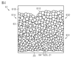
- FIG. 6 is an enlarged schematic diagram of the outer surface of the first base electrode in the electronic component.
- FIG. 7 is a graph showing the relationship between weight loss rate and temperature when the test object is fired.
- FIG. 8 is a flowchart illustrating a method for manufacturing electronic components.
- electronic component 10 is a multilayer ceramic capacitor.
- the electronic component 10 includes an element body 20.
- the element body 20 has a substantially quadrangular prism shape and has a central axis CA.
- the axis extending along the central axis CA will be referred to as a first axis X.
- one of the axes orthogonal to the first axis X is defined as a second axis Y.
- an axis perpendicular to the first axis X and the second axis Y is defined as a third axis Z.
- one of the directions along the first axis X is defined as a first positive direction X1, and the direction opposite to the first positive direction X1 among the directions along the first axis X is defined as a first negative direction X2.
- one of the directions along the second axis Y is defined as a second positive direction Y1, and the direction opposite to the second positive direction Y1 among the directions along the second axis Y is defined as a second negative direction Y2.
- one of the directions along the third axis Z is defined as a third positive direction Z1, and among the directions along the third axis Z, the direction opposite to the third positive direction Z1 is defined as a third negative direction Z2.
- the outer surface 21 of the element body 20 has six flat surfaces 22.
- the "surface" of the element body 20 herein refers to what can be observed as a surface when the entire element body 20 is observed. That is, even if there are minute irregularities or steps that cannot be seen unless a part of the element body 20 is observed under a microscope or the like, it is expressed as a flat or curved surface.
- the six planes 22 face different directions.
- the six planes 22 are roughly divided into a first end surface 22A facing the first positive direction X1, a second end surface 22B facing the first negative direction X2, and four side surfaces 22C.
- the four side surfaces 22C each include a surface facing the third positive direction Z1, a surface facing the third negative direction Z2, a surface facing the second positive direction Y1, and a surface facing the second negative direction Y2. .
- the outer surface 21 of the element body 20 has 12 boundary surfaces 23.
- the boundary surface 23 includes a curved surface existing at the boundary between adjacent planes 22. That is, the boundary surface 23 includes, for example, a curved surface formed by rounding the corners of the adjacent planes 22.
- the outer surface 21 of the element body 20 has eight spherical corner surfaces 24.
- the corner surface 24 is a boundary between three adjacent planes 22.
- the corner surface 24 includes a curved surface where the three boundary surfaces 23 intersect. That is, the corner surface 24 includes a curved surface formed by, for example, rounding the corner formed by the three adjacent planes 22.
- the dimension of the element body 20 in the direction along the first axis X is larger than the dimension in the direction along the third axis Z.
- the material of the element body 20 is dielectric ceramic. Specifically, the material of the element body 20 has BaTiO 3 as a main component. Further, the material of the element body 20 may be mainly composed of CaTiO 3 , SrTiO 3 , CaZrO 3 or the like. Further, the material of the element body 20 may contain a Mn compound, a Co compound, a Si compound, a rare earth compound, or the like as a subcomponent.
- the electronic component 10 includes four first internal electrodes 41 and four second internal electrodes 42 as wiring.
- the first internal electrode 41 and the second internal electrode 42 are embedded inside the element body 20 .
- the material of the first internal electrode 41 is a conductive material.
- the material of the first internal electrode 41 is Ni.
- the material of the first internal electrode 41 may further include metals such as Ni, Cu, Ag, Au, Pt, Sn, and Pd, or alloys containing these metals.
- the material of the second internal electrode 42 is the same as that of the first internal electrode 41.
- the shape of the first internal electrode 41 is a rectangular plate.
- the main surface of the first internal electrode 41 is perpendicular to the second axis Y.
- the shape of the second internal electrode 42 is the same rectangular plate shape as the first internal electrode 41.
- the main surface of the second internal electrode 42 is perpendicular to the second axis Y, similarly to the first internal electrode 41.
- the dimension of the first internal electrode 41 in the direction along the first axis X is smaller than the dimension of the element body 20 in the direction along the first axis X. Further, as shown in FIG. 1, the dimension of the first internal electrode 41 in the direction along the third axis Z is approximately two-thirds of the dimension of the element body 20 in the direction along the third axis Z. The dimensions of the second internal electrode 42 in each direction are the same as those of the first internal electrode 41.
- the first internal electrodes 41 and the second internal electrodes 42 are located alternately in the direction along the second axis Y. That is, a total of eight internal electrodes are alternately arranged in the order of the first internal electrodes 41 and the second internal electrodes 42 from the side surface 22C facing the second positive direction Y1 toward the second negative direction Y2. In this embodiment, the distance between each internal electrode in the direction along the second axis Y is equal.
- the four first internal electrodes 41 and the four second internal electrodes 42 are both located at the center of the element body 20 in the direction along the third axis Z.
- the first internal electrode 41 is located closer to the first positive direction X1.
- the second internal electrode 42 is located closer to the first negative direction X2.
- the end of the first internal electrode 41 on the first positive direction X1 side matches the end of the element body 20 on the first positive direction X1 side.
- the end of the first internal electrode 41 on the first negative direction X2 side is located inside the element body 20 and does not reach the end of the element body 20 on the first negative direction X2 side.
- the end of the second internal electrode 42 on the first negative direction X2 side coincides with the end of the element body 20 on the first negative direction X2 side.
- the end of the second internal electrode 42 on the first positive direction X1 side is located inside the element body 20 and does not reach the end of the element body 20 on the first positive direction X1 side.
- the electronic component 10 includes a first external electrode 61 and a second external electrode 62.
- the first external electrode 61 includes a first base electrode 61A and a first metal layer 61B.
- the first base electrode 61A is laminated on a portion of the outer surface 21 of the element body 20, including the first end surface 22A.
- the first base electrode 61A is a five-sided electrode that covers the first end surface 22A of the element body 20 and a portion of the four side surfaces 22C on the first positive direction X1 side.
- the materials of the first base electrode 61A are copper and glass.
- the first base electrode 61A is a sintered body.
- the first metal layer 61B covers the first base electrode 61A from the outside. Therefore, the first metal layer 61B is laminated on the first base electrode 61A. Further, a portion of the first metal layer 61B protrudes from the first base electrode 61A.
- the first metal layer 61B has a two-layer structure including a nickel layer and a tin layer in order from the first base electrode 61A side. Note that the first metal layer 61B does not penetrate into the inside of the first base electrode 61A.
- the second external electrode 62 includes a second base electrode 62A and a second metal layer 62B.
- the second base electrode 62A is laminated on a portion of the outer surface 21 of the element body 20, including the second end surface 22B.
- the second base electrode 62A is a five-sided electrode that covers the second end surface 22B of the element body 20 and a portion of the four side surfaces 22C on the first negative direction X2 side.
- the material of the second base electrode 62A is the same as that of the first external electrode 61, which is copper and glass. Further, the second base electrode 62A is a sintered body like the first base electrode 61A.
- the second metal layer 62B covers the second base electrode 62A from the outside. Therefore, the second metal layer 62B is laminated on the second base electrode 62A. Further, a portion of the second metal layer 62B protrudes from the second base electrode 62A. Although not shown, the second metal layer 62B, like the first metal layer 61B, has a two-layer structure including a nickel layer and a tin layer in order from the second base electrode 62A side. Note that the second metal layer 62B does not penetrate into the second base electrode 62A.
- the second external electrode 62 does not reach the first external electrode 61 on the side surface 22C, and is arranged apart from the first external electrode 61 in the direction along the first axis X. Further, on the side surface 22C of the element body 20, the first external electrode 61 and the second external electrode 62 are not stacked at the central portion in the direction along the first axis X. Note that in FIGS. 1 to 3, the first external electrode 61 and the second external electrode 62 are illustrated by two-dot chain lines.
- the first base electrode 61A contains copper and silicon. Further, the first base electrode 61A is a sintered body. Note that, although the first base electrode 61A will be described as a representative example below, the same applies to the second base electrode 62A.
- the weight ratio of copper to silicon in the first base electrode 61A is 0.5 or more and 2 or less. As shown in FIG. 4, at least a portion of the copper in the first base electrode 61A is copper particles 63. Further, silicon in the first base electrode 61A exists as a silicone resin 64. Note that the silicone resin 64 is a polymer consisting of siloxane bonds and Si--C bonds.
- the flatness F of the copper particles 63 is 0.5 or less. Therefore, the copper particles 63 have a generally spherical appearance.
- the flattening ratio F is calculated as follows. First, as shown in FIG. 6, the contours of the copper particles 63 are acquired by image processing using a scanning transmission electron microscope (STEM). The image is acquired by a scanning transmission electron microscope adjusted to a magnification of, for example, 200,000 times or more. The photographing parameters were an accelerating voltage of 200 kV and a focusing lens aperture of #3. Platinum sputter coating was performed as a pretreatment for photography.
- the image acquired under these conditions is analyzed, and the half length of the longest line segment among the line segments connecting the edges of one copper particle 63 is defined as the semi-major axis a. Further, the half length of a line segment that is perpendicular to the semi-major axis a and connects the edges of the copper particles 63 is defined as the semi-minor radius b.
- the first base electrode 61A is divided into a first portion 631 on the inner surface 620 side of the first base electrode 61A, a second portion 632 on the outer surface 610 side of the first base electrode 61A, Divide into two equal parts.
- the inner surface 620 is a boundary surface of the first base electrode 61A on the side closer to the element body 20.
- the outer surface 610 is the outer surface of the first base electrode 61A on the side opposite to the element body 20.
- the position where the first base electrode 61A is divided into two equal parts is the position where the average value of the thickness H of the first base electrode 61A, which will be described later, is divided into two equal parts.
- the average value of the particle diameter of the copper particles 63 is different between the first portion 631 and the second portion 632. Specifically, the average value of the particle size of the copper particles 63 in the first portion 631 is smaller than the average value of the particle size of the copper particles 63 in the second portion 632. That is, the particle size of the copper particles 63 located in the first portion 631 is often smaller than the particle size of the copper particles 63 located in the second portion 632. As a whole, the particle size of the copper particles 63 becomes smaller toward the inner surface 620 within the first base electrode 61A.
- the particle size of the copper particles 63 is twice the average length of the major axis a and the minor axis b.
- the average value of the particle diameters of the copper particles 63 in the first portion 631 is the average value of the particle diameters of the five copper particles 63 located in the first portion 631.
- the average value of the particle diameters of the copper particles 63 in the second portion 632 is the average value of the particle diameters of the five copper particles 63 located in the second portion 632.
- the silicone resin 64 as silicon is distributed in a network shape. Specifically, when the first base electrode 61A is viewed in cross section, the silicone resin 64 is distributed so as to fill the spaces between the plurality of copper particles 63. In this embodiment, the silicone resin 64 is distributed in a network shape, reflecting the fact that the plurality of copper particles 63 are in general point contact with each other. Further, a portion of the silicone resin 64 is in the form of a lump.
- the lump-like silicone resin 64 is a condensation of a part of the mesh-like silicone resin 64.
- the first portion 631 has a higher proportion of bulk silicone resin 64 than the second portion 632.
- the proportion of silicone resin 64 in the first portion 631 of the first base electrode 61A is higher than the proportion of silicone resin 64 in the second portion 632 of the first base electrode 61A.
- the proportion of the silicone resin 64 is calculated as follows. First, a cross section of the first base electrode 61A is photographed using a scanning electron microscope (SEM-EDX). The image is acquired by a scanning electron microscope adjusted to a magnification of, for example, 200,000 times or more. The imaging parameters were a spot diameter of 5, a time constant of Rate 1, and a number of integrations of 100. Next, for the photographed image, the area occupied by the silicone resin 64 within a certain square range is calculated.
- the area of the silicone resin 64 with respect to the area of the square is defined as the ratio of the silicone resin 64.
- a square area is defined so as not to protrude from the first portion 631, and the proportion of the silicone resin 64 is calculated.
- the proportion of the silicone resin 64 is calculated at three or more points, and the average value thereof is taken as the proportion of the silicone resin 64 in the first portion 631. Note that the same applies to the second portion 632.
- the thickness H of the first base electrode 61A is calculated as follows. First, a cross section including the outer surface 610 and inner surface 620 of the first base electrode 61A is photographed using a scanning transmission electron microscope. The parameters for imaging are the same as those for imaging using the scanning transmission electron microscope described above. Next, the range in the direction along the outer surface 610 of the first base electrode 61A is specified for the photographed image. In this range, the cross-sectional area of the first base electrode 61A is calculated by image processing for a measurement range of at least 5 ⁇ m or more.
- the thickness H of the first base electrode 61A is calculated by dividing the cross-sectional area of the first base electrode 61A in the calculated measurement range by the length of the measurement range. That is, the thickness H of the first base electrode 61A is the thickness within the measurement range.
- the first base electrode 61A has gaps PA between the copper particles 63 in which no synthetic resin such as the silicone resin 64 is present.
- the proportion of voids PA in the first base electrode 61A is less than 5%. In this way, if the proportion of the voids PA in the first base electrode 61A is less than 5%, it can be said that the silicone resin 64 is distributed so as to fill the spaces between the copper particles 63. Note that in FIG. 5, the void PA is schematically illustrated.
- the porosity measured as follows is used. First, the first base electrode 61A is observed in a square area of 500 nm on a side using a scanning transmission electron microscope at a magnification of 200,000 times or more. In this range, the areas where the copper particles 63 and the silicone resin 64 are not present, that is, the total area of the voids PA, are calculated by image processing. Then, the porosity is calculated from the ratio of the total area of the voids PA to the area of the observation range. This step is repeated at four locations on the first base electrode 61A, and the average value of the porosity in each range is taken as the percentage of voids PA in the first base electrode 61A.
- the method for manufacturing the electronic component 10 further includes a laminate preparation step S11, an R chamfering step S12, a conductor coating step S13, a curing step S14, and a plating step S15. There is.
- a laminate which is the element body 20 without the boundary surface 23 and the corner surface 24 is prepared. That is, the laminate is in a state before R-chamfering and is in the shape of a rectangular parallelepiped with six planes 22.
- a plurality of ceramic sheets that will become the element body 20 are prepared. The sheet is in the form of a thin plate. A conductive paste that will become the first internal electrode 41 is laminated on the sheet. A ceramic sheet that will become the element body 20 is laminated on the lamination paste. A conductive paste that will become the second internal electrode 42 is laminated on the sheet. In this way, the ceramic sheet and the conductive paste are laminated.
- the stacked sheets are pressed together in the stacking direction by means such as a mold press. Thereafter, the crimped product is cut into a predetermined size to form an unfired laminate. Thereafter, a laminate is prepared by firing the unfired laminate at a high temperature.
- an R chamfering process S12 is performed.
- a boundary surface 23 and a corner surface 24 are formed on the laminate prepared in the laminate preparation step S11.
- the corners of the laminate are rounded to form a curved boundary surface 23 and a curved corner surface 24 .
- a conductor coating step S13 is performed.
- a conductor paste is applied to two locations: a portion of the first end surface 22A of the element body 20 and a portion of the second end surface 22B of the element body 20.
- the conductive paste is applied so as to cover the entire first end surface 22A and a portion of the four side surfaces 22C.
- a conductive paste is applied so as to cover the entire second end surface 22B and a portion of the four side surfaces 22C.
- the conductive paste is a complex ink.
- the conductive paste of the complex ink is created as follows. First, an amine compound such as 2-ethylhexylamine and an alcohol amine such as 2-amino-2-methylpropanol are mixed. Then, a silicon component such as a silicone resin is added in an amount of 10 to 300 wt% based on the weight of Cu alone. Then, a metal salt is further added and dissolved to create a conductive paste. That is, the conductive paste contains a copper component and a silicon component. The sintering start temperature of the copper component is 170 degrees, and the hardening start temperature of the silicon component is 250 degrees. Note that how to determine the sintering start temperature of the copper component and the hardening start temperature of the silicon component will be described later.
- a curing step S14 is performed. Specifically, in the curing step S14, the element body 20 coated with the conductive paste is heated. In this embodiment, the element body 20 coated with the conductive paste is heated in a nitrogen atmosphere. Then, it is maintained at a temperature within the range of 300 degrees to 600 degrees. As a result, the conductive paste is fired. During firing of the conductive paste, first, sintering of the copper component contained in the first base electrode 61A and the second base electrode 62A is started. At the time when sintering of the copper component is started, the silicon component is not hardened and has fluidity. Therefore, the silicon component fills the gaps between the copper components.
- the hardening of the silicon component contained in the first base electrode 61A and the second base electrode 62A is started. That is, the hardening start temperature of the silicon component is higher than the sintering start temperature of the copper component. Then, copper particles 63 are generated by sintering the copper component. Furthermore, silicone resin 64 is generated by curing the silicon component. Further, as described above, since the hardening start temperature of the silicon component is higher than the sintering start temperature of the copper component, the mesh-like silicone resin 64 fills the gaps between the copper particles 63.
- the first base electrode 61A and the second base electrode 62A as described above are formed.
- the silicone resin 64 forms a dense film that fills the gaps between the copper particles 63.
- the proportion of the voids PA in the first base electrode 61A and the second base electrode 62A becomes smaller.
- a plating step S15 is performed. Electroplating is performed on the first base electrode 61A and the second base electrode 62A. As a result, a first metal layer 61B is formed on the surface of the first base electrode 61A. Further, a second metal layer 62B is formed on the surface of the second base electrode 62A. Although not shown, the first metal layer 61B and the second metal layer 62B are electroplated with two types of metal, nickel and tin, so that they have a two-layer structure. In this way, electronic component 10 is formed.
- the sintering start temperature of the copper component was measured as follows. First, a complex ink composed of a copper component is created. Then, the weight change of the complex ink during firing was measured using a thermal analyzer (Thermo Plus EVO2 manufactured by Rigaku).
- the weight reduction rate is defined as 100% when the temperature is set to 600 degrees with respect to the weight of the complex ink before sintering. Then, the temperature at which the weight reduction rate after starting sintering is 99% is defined as the sintering start temperature. For example, if the temperature is 600 degrees and the amount reduced from before sintering is 10 mg, the sintering start temperature is the temperature at which the weight reduction amount is 9.9 mg, that is, the weight reduction rate is 99%. shall be.
- the sintering start temperature of the copper component was measured using the complex ink as a test subject under the following conditions.
- the temperature at the start of the test was 40 degrees.
- the temperature increase rate was 10 degrees/min.
- the temperature at the end of the test was 600 degrees.
- FIG. 7 when the weight loss at 600 degrees is normalized to 100%, a 99% weight loss occurs when the temperature is 170 degrees. That is, the sintering start temperature of the copper component is 170 degrees.
- the curing temperature of the silicon component was measured as follows. In the measurement test, a stretched silicon paste was used as the test object. In the measurement test, the test object was fired. At this time, the test was performed while changing the maximum value of the firing temperature in 10 degree increments. After firing, the test object was touched with a finger, and the temperature at which the tackiness was felt was taken as the curing start temperature. The tackiness was evaluated based on JIS K 5600-1-1 4.3.5 (c). The tackiness in this embodiment is the condition in which there are no scratches on the painted surface in the evaluation based on JIS above.
- the test object in the above test is a slide glass with silicone resin squeegeeed to a thickness of 500 ⁇ m.
- the test object is placed on a hot plate.
- the test piece was heated at 150 degrees for 10 minutes.
- the test piece was evaluated based on the above JIS.
- the heating temperature was increased by 10 degrees and the test piece was heated for 10 minutes.
- the evaluation based on the above JIS was performed again.In this way, the evaluation based on the above JIS was performed every time the heating temperature of the test piece was increased by 10 degrees, and the temperature at which it was felt that the tackiness had disappeared was determined as the hardening start temperature of the silicon component. Note that the measurement was performed in the atmosphere. In this embodiment, the hardening start temperature of silicon was 250 degrees in this test.
- Examples 1 to 12 and Comparative Examples 1 to 4 The electronic components of Examples 1 to 12 and Comparative Examples 1 to 4 will be described below.
- the proportion of voids in the first base electrode is 1%.
- the average value of the thickness H of the first base electrode is 550 nm.
- the oblateness of the copper particles is 0.2.
- the proportion of voids in the first base electrode is 1%.
- the average value of the thickness H of the first base electrode is 550 nm.
- the oblateness of the copper particles is 0.4.
- the proportion of voids in the first base electrode is 3%.
- the average value of the thickness H of the first base electrode is 500 nm.
- the oblateness of the copper particles is 0.5.
- the proportion of voids in the first base electrode is 1%.
- the average value of the thickness H of the first base electrode is 750 nm.
- the oblateness of the copper particles is 0.2.
- the proportion of voids in the first base electrode is 3%.
- the average value of the thickness H of the first base electrode is 800 nm.
- the oblateness of the copper particles is 0.4.
- the proportion of voids in the first base electrode is 3%.
- the average value of the thickness H of the first base electrode is 750 nm.
- the oblateness of the copper particles is 0.5.
- the proportion of voids in the first base electrode was 2%.
- the average value of the thickness H of the first base electrode is 1200 nm.
- the oblateness of the copper particles is 0.2.
- the proportion of voids in the first base electrode was 3%.
- the average value of the thickness H of the first base electrode is 1100 nm.
- the oblateness of the copper particles is 0.4.
- the proportion of voids in the first base electrode was 4%.
- the average value of the thickness H of the first base electrode is 1300 nm.
- the oblateness of the copper particles is 0.5.
- the proportion of voids in the first base electrode was 3%.
- the average value of the thickness H of the first base electrode is 1800 nm.
- the oblateness of the copper particles is 0.2.
- the proportion of voids in the first base electrode was 4%.
- the average value of the thickness H of the first base electrode is 1950 nm.
- the oblateness of the copper particles is 0.4.
- the proportion of voids in the first base electrode is 4%.
- the average value of the thickness H of the first base electrode is 2000 nm.
- the oblateness of the copper particles is 0.5.
- the proportion of voids in the first base electrode was 3%.
- the average value of the thickness H of the first base electrode is 350 nm.
- the oblateness of the copper particles is 0.2.
- the proportion of voids in the first base electrode is 5%.
- the average value of the thickness H of the first base electrode is 750 nm.
- the oblateness of the copper particles is 0.6.
- the proportion of voids in the first base electrode was 8%.
- the average value of the thickness H of the first base electrode is 750 nm.
- the oblateness of the copper particles is 0.7.
- the proportion of voids in the first base electrode was 4%.
- the average value of the thickness H of the first base electrode is 2200 nm.
- the oblateness of the copper particles is 0.3.
- the appearance of the first base electrode was inspected by observation. In the inspection, first, the first base electrode was observed from the first end surface side of the element using an optical microscope. Then, the presence or absence of cracks in the first base electrode and the presence or absence of film breakage were determined. It was determined that film breakage occurred when the first base electrode could not cover the entire first end surface. Note that the appearance of the first base electrode was observed before the first metal layer was formed on the first base electrode.
- the first base electrode of the electronic components of Examples 1 to 12 and Comparative Examples 2 and 3 was a continuous film that covered the entire first end surface of the element body.
- film breakage was observed.
- cracks were observed in the first base conductor of the electronic component of Comparative Example 4.
- the cross section of the first base electrode was observed and inspected. Specifically, the presence or absence of penetration of the plating solution into the first base electrode was observed.
- a cross-sectional image of the first base electrode was taken using a scanning electron microscope (SEM-EDX). The images were taken at a magnification of 200,000 times or more on four different cross sections. In each cross section, if a component of the first metal layer is detected at a position inside the outer surface of the first base electrode by a thickness of 10% or more of the average thickness of the first base electrode 61A, plating is detected. It was determined that there was liquid intrusion. In addition, in the determination, if plating solution intrusion was observed in even one of the four cross sections observed, it was determined that there was plating solution intrusion.
- the plating solution invaded the first base electrode when the average thickness of the first base electrode was greater than 2000 nm.
- the average value of the thickness of the first base electrode is preferably 2000 nm or less.
- the plating solution invaded the first base electrode when the oblateness of the copper particles was larger than 0.5.
- the flatness of the copper particles is preferably 0.5 or less.
- the plating solution invaded the first base electrode when the porosity of the first base electrode was 5% or more. .
- the porosity of the first base electrode is preferably less than 5%.
- the silicone resin 64 is distributed around the copper particles 63 without gaps.
- the first base electrode 61A is a dense and dense film. Therefore, according to the above configuration, it is possible to suppress, for example, a plating solution for forming the first metal layer 61B from entering the first base electrode 61A.
- the silicone resin 64 has higher adhesion to other members than the copper particles 63.
- the proportion of silicone resin 64 in the first portion 631 of the first base electrode 61A is higher than the proportion of silicone resin 64 in the second portion 632 of the first base electrode 61A.
- the silicone resin 64 it is highly likely that the silicone resin 64 is exposed on the inner surface 620 of the first base electrode 61A. Therefore, the silicone resin 64 easily adheres to the element body 20, and the first base electrode 61A is difficult to peel off from the element body 20.
- the average value of the thickness H of the first base electrode 61A is 700 nm.
- the average value of the thickness H of the first base electrode 61A is this value, stress generated during sintering can be reduced.
- the average value of the thickness H of the first base electrode 61A is within the range of 500 nm or more and 2000 nm or less. Therefore, according to this configuration, the occurrence of film breakage and cracks in the first base electrode 61A can be suppressed from the results of the above-mentioned observational inspection. Furthermore, this configuration can be said to be highly effective in suppressing the plating solution and the like for forming the first metal layer 61B from entering the first base electrode 61A.
- the average value of the particle size of the copper particles 63 in the first portion 631 of the first base electrode 61A is the same as the particle size of the copper particles 63 in the second portion 632 of the first base electrode 61A. smaller than the average value. That is, the copper particles 63 having small particle diameters tend to be densely packed on the inner surface 620. Thereby, the electrical connection between the first base electrode 61A and the first internal electrode 41 can be easily established.
- the hardening step S14 sintering of the copper component in the conductor paste is started before hardening of the silicon component.
- the silicon component is filled into the gaps between the copper grain components.
- the silicon component is distributed in the gaps between the copper components. This suppresses the progress of sintering of the copper component. As a result, the particle size of the copper particles 63 formed is difficult to increase. That is, according to the embodiment described above, stress caused by the copper particles 63 becoming excessively large during sintering can be suppressed.
- the copper components may connect to each other and form a film before the silicon component is hardened. If the copper component is connected in a film-like manner as described above, it becomes difficult for the silicon component to be distributed in a network shape. As in the above embodiment, if the difference between the sintering start temperature of the copper component and the hardening start temperature of the silicon component is about 80 degrees, the copper component will not connect into a film as described above. It can be prevented.
- the electronic component 10 is not limited to a multilayer ceramic capacitor.
- the electronic component 10 may be a piezoelectric component, a thermistor, an inductor, etc. that includes the element body 20, the first external electrode 61, and the second external electrode 62.
- the material of the element body 20 may be a dielectric material, a piezoelectric material, a magnetic material such as ferrite, a composite material of synthetic resin and metal, or the like.
- the conductor paste may be nano ink. If it is nano ink, it is created as follows. Nanometal powder is dispersed in a solvent containing cellosolves, carbitols, hydrocarbons, aromatics, and the like. Then, various silicone-modified resins, silicone resins, sol-gel materials, etc. are added in an amount of 10 to 300 wt % based on the weight of Cu alone. The nano-ink conductor paste may be created in this way, or a different method may be used.
- the material used when the conductor paste is used as a complex ink is not limited to the example of the above embodiment.
- the amine compound may be a primary amine, a secondary amine, or a tertiary amine, and the number of N atoms is not limited.
- primary amines such as octylamine and hexylamine
- secondary amines such as di-n-butylamine
- tertiary amines such as N,N-dimethylhexylamine
- the amine compound may be an alcohol amine, a diamine, or the like, and the positional relationship between the N atom and the OH group is not specified, such as ⁇ , ⁇ , or ⁇ positions.
- the number of N and O atoms in one molecule is not particularly limited either.
- ⁇ -hydroxyamines such as 2-dimethylaminoethanol and 2-ethylaminoethanol
- ⁇ -hydroxyamines such as 3-amino-1-propanol and 4-amino-2-butanol
- it may be a diamine such as ethylenediamine or a cyclic diamine such as piperazine.
- the silicon component may be, for example, various silicone-modified resins such as epoxy resins, polyester resins, and phenol resins, sol-gel materials, and the like.
- the metal salt a metal salt made of formic acid, acetic acid, oxalic acid, other organic acids, etc. may be employed. Examples of this type of metal salt include anhydrous copper formate.
- first internal electrodes 41 and second internal electrodes 42 are not limited to the example of the above embodiment.
- the number of first internal electrodes 41 may be less than four or more than four. The same applies to the second internal electrode 42 in this regard.
- the electronic component 10 may include a glass film.
- the glass film may be formed to cover a part of the outer surface 21 of the element body 20. In other words, even if there is a glass film covering the element body 20, the electrical connection between the first internal electrode 41 and the first external electrode 61, and the electrical connection between the second internal electrode 42 and the second external electrode 62 is maintained. It is sufficient if this is ensured.
- the proportion of the silicone resin 64 in the first portion 631 of the first base electrode 61A may be lower than the proportion of the silicone resin 64 in the second portion 632 of the first base electrode 61A. However, it may be the same. In this respect, the same applies to the second base electrode 62A.
- the average value of the thickness H of the first base electrode 61A is not limited to the example of the above embodiment. Note that in order to reduce stress generated during firing, the average value of the thickness H of the first base electrode 61A is preferably 500 nm or more and 2000 nm or less. In this respect, the same applies to the second base electrode 62A.
- the average value of the particle size of the copper particles 63 in the first portion 631 of the first base electrode 61A is the average value of the particle size of the copper particles 63 in the second portion 632 of the first base electrode 61A. It can be the same as or smaller. In this respect, the same applies to the second base electrode 62A.
- silicon is not limited to the silicone resin 64.
- silicon may be silica (silicon dioxide) or the like.
- the curing step S14 may be performed in multiple steps. That is, the firing may be performed in multiple steps.
- the difference between the sintering start temperature of the copper component and the hardening start temperature of the silicon component of the conductive paste is not limited to the example of the above embodiment. However, in order to keep the copper component spherical, it is preferable that the difference in these starting temperatures be 100 degrees or less.
- the curing start temperature of the silicon component may be measured by a different method.
- the sintering start temperature of the copper component may be measured by a different method. For example, first, pellets of nanopowder made of a copper component are created. Then, shrinkage of the pellet during firing is measured using a thermomechanical analyzer TMA (TA7000, manufactured by Hitachi High-Tech Science). Specifically, a cylindrical pellet with a diameter of 5 mm and a height of 5 mm is used as a test object, and the height of the pellet during firing is measured. Then, when a two-dimensional graph of height and temperature is made, the temperature at which the height becomes an inflection point is defined as the sintering start temperature.
- TMA thermomechanical analyzer
- the first metal layer 61B may be formed by other methods such as sputtering. The same applies to the second metal layer 62B in this respect.
- the material of the first metal layer 61B is not limited to the example of the above embodiment.
- the first metal layer 61B may be made of only nickel, only tin, or may contain other materials.
- the material of the first metal layer 61B may be copper, silver, gold, palladium, or the like. The same applies to the second metal layer 62B in this respect.
- the copper particles 63 may be an alloy containing a copper component.
- the copper particles 63 may be an alloy of copper and a metal such as silver, gold, palladium, or nickel.
- An element body and an external electrode that covers a part of the outer surface of the element body has a base electrode and a metal layer that covers the outer surface of the base electrode, and the base electrode contains copper and silicon, at least a part of the copper is copper particles having an oblateness of 0.5 or less, and when the base electrode is viewed in cross section, the silicon contains a plurality of the An electronic component that is distributed between copper particles.
- the base electrode When the base electrode is divided into two parts: a first part located on the element body side and a second part on the opposite side from the element body, the proportion of silicon in the first part is equal to the proportion of silicon in the first part.
- the average value of the thickness of the base electrode is 500 nm or more. , and 2000 nm or less, the electronic component according to [1] or [2].
- the particle size of the copper particles in the first part is The electronic component according to any one of [1] to [3], wherein the average value is smaller than the average value of the particle diameter of the copper particles in the second portion.
- the hardening start temperature of the silicon component is higher than the sintering start temperature of the copper component, and the difference between the hardening start temperature of the silicon component and the sintering start temperature of the copper component is A method for manufacturing electronic components at a temperature of 100 degrees or less.
Landscapes
- Engineering & Computer Science (AREA)
- Power Engineering (AREA)
- Microelectronics & Electronic Packaging (AREA)
- Manufacturing & Machinery (AREA)
- Physics & Mathematics (AREA)
- Electromagnetism (AREA)
- Chemical & Material Sciences (AREA)
- Materials Engineering (AREA)
- Ceramic Engineering (AREA)
- Fixed Capacitors And Capacitor Manufacturing Machines (AREA)
Priority Applications (3)
| Application Number | Priority Date | Filing Date | Title |
|---|---|---|---|
| CN202380014573.7A CN118266052A (zh) | 2022-08-08 | 2023-07-28 | 电子部件以及电子部件的制造方法 |
| JP2024540378A JPWO2024034425A1 (https=) | 2022-08-08 | 2023-07-28 | |
| US18/612,190 US12567541B2 (en) | 2022-08-08 | 2024-03-21 | Electronic component and method for manufacturing electronic component |
Applications Claiming Priority (2)
| Application Number | Priority Date | Filing Date | Title |
|---|---|---|---|
| JP2022126338 | 2022-08-08 | ||
| JP2022-126338 | 2022-08-08 |
Related Child Applications (1)
| Application Number | Title | Priority Date | Filing Date |
|---|---|---|---|
| US18/612,190 Continuation US12567541B2 (en) | 2022-08-08 | 2024-03-21 | Electronic component and method for manufacturing electronic component |
Publications (1)
| Publication Number | Publication Date |
|---|---|
| WO2024034425A1 true WO2024034425A1 (ja) | 2024-02-15 |
Family
ID=89851600
Family Applications (1)
| Application Number | Title | Priority Date | Filing Date |
|---|---|---|---|
| PCT/JP2023/027678 Ceased WO2024034425A1 (ja) | 2022-08-08 | 2023-07-28 | 電子部品及び電子部品の製造方法 |
Country Status (4)
| Country | Link |
|---|---|
| US (1) | US12567541B2 (https=) |
| JP (1) | JPWO2024034425A1 (https=) |
| CN (1) | CN118266052A (https=) |
| WO (1) | WO2024034425A1 (https=) |
Cited By (2)
| Publication number | Priority date | Publication date | Assignee | Title |
|---|---|---|---|---|
| WO2025220548A1 (ja) * | 2024-04-15 | 2025-10-23 | 株式会社村田製作所 | 電子部品 |
| WO2025239223A1 (ja) * | 2024-05-15 | 2025-11-20 | 株式会社村田製作所 | 電子部品及び電子部品の製造方法 |
Citations (3)
| Publication number | Priority date | Publication date | Assignee | Title |
|---|---|---|---|---|
| WO2016186053A1 (ja) * | 2015-05-21 | 2016-11-24 | 株式会社村田製作所 | 電子部品 |
| JP2021019123A (ja) * | 2019-07-22 | 2021-02-15 | Tdk株式会社 | セラミック電子部品 |
| JP2022057923A (ja) * | 2020-09-30 | 2022-04-11 | 株式会社村田製作所 | 積層セラミックコンデンサ |
Family Cites Families (6)
| Publication number | Priority date | Publication date | Assignee | Title |
|---|---|---|---|---|
| JP5206440B2 (ja) | 2009-01-16 | 2013-06-12 | Tdk株式会社 | セラミック電子部品 |
| KR101228752B1 (ko) * | 2011-11-04 | 2013-01-31 | 삼성전기주식회사 | 적층 세라믹 전자 부품 및 그 제조 방법 |
| JP2015053495A (ja) * | 2014-10-07 | 2015-03-19 | 株式会社村田製作所 | セラミック電子部品およびその製造方法 |
| JP6780673B2 (ja) * | 2018-03-30 | 2020-11-04 | 株式会社村田製作所 | 積層セラミックコンデンサおよびその実装構造 |
| KR102070235B1 (ko) * | 2018-10-29 | 2020-01-28 | 삼성전기주식회사 | 커패시터 부품 |
| WO2021033387A1 (ja) * | 2019-08-22 | 2021-02-25 | 株式会社村田製作所 | 電子部品 |
-
2023
- 2023-07-28 WO PCT/JP2023/027678 patent/WO2024034425A1/ja not_active Ceased
- 2023-07-28 CN CN202380014573.7A patent/CN118266052A/zh active Pending
- 2023-07-28 JP JP2024540378A patent/JPWO2024034425A1/ja active Pending
-
2024
- 2024-03-21 US US18/612,190 patent/US12567541B2/en active Active
Patent Citations (3)
| Publication number | Priority date | Publication date | Assignee | Title |
|---|---|---|---|---|
| WO2016186053A1 (ja) * | 2015-05-21 | 2016-11-24 | 株式会社村田製作所 | 電子部品 |
| JP2021019123A (ja) * | 2019-07-22 | 2021-02-15 | Tdk株式会社 | セラミック電子部品 |
| JP2022057923A (ja) * | 2020-09-30 | 2022-04-11 | 株式会社村田製作所 | 積層セラミックコンデンサ |
Cited By (2)
| Publication number | Priority date | Publication date | Assignee | Title |
|---|---|---|---|---|
| WO2025220548A1 (ja) * | 2024-04-15 | 2025-10-23 | 株式会社村田製作所 | 電子部品 |
| WO2025239223A1 (ja) * | 2024-05-15 | 2025-11-20 | 株式会社村田製作所 | 電子部品及び電子部品の製造方法 |
Also Published As
| Publication number | Publication date |
|---|---|
| CN118266052A (zh) | 2024-06-28 |
| US12567541B2 (en) | 2026-03-03 |
| US20240234036A1 (en) | 2024-07-11 |
| JPWO2024034425A1 (https=) | 2024-02-15 |
Similar Documents
| Publication | Publication Date | Title |
|---|---|---|
| US10840021B2 (en) | Multilayer ceramic electronic component | |
| US10714261B2 (en) | Multilayer ceramic capacitor | |
| US10529486B2 (en) | Conductive paste for external electrode and method for manufacturing electronic component including the conductive paste for external electrode | |
| CN111952076B (zh) | 电子部件的安装构造体及其制造方法 | |
| US10020117B2 (en) | Multi-layer ceramic capacitor and method of producing the same | |
| US11062848B2 (en) | Multilayer ceramic electronic component | |
| US12567541B2 (en) | Electronic component and method for manufacturing electronic component | |
| US20140063684A1 (en) | Conductive paste composition for external electrode, multilayered ceramic component including the same and manufacturing method thereof | |
| KR20160079748A (ko) | 세라믹 전자부품 및 그 제조방법 | |
| JP2012019159A (ja) | セラミック電子部品 | |
| US20150014900A1 (en) | Composite conductive powder, conductive paste for external electrode including the same, and manufacturing method of multilayer ceramic capacitor | |
| US20250308798A1 (en) | Multilayer ceramic electronic component | |
| US20240420894A1 (en) | Multilayer ceramic electronic component | |
| JP2016063079A (ja) | 抵抗素子およびその製造方法 | |
| JP2005072452A (ja) | 積層型電子部品およびその製法 | |
| JP7582508B2 (ja) | 電子部品 | |
| JP7715289B2 (ja) | 電子部品 | |
| JP2005101301A (ja) | 積層型電子部品およびその製法 | |
| WO2023084878A1 (ja) | 電子部品 | |
| CN119317986A (zh) | 层叠陶瓷电子部件 | |
| US20250149248A1 (en) | Electronic component that suppresses migration in external electodes | |
| WO2024166447A1 (ja) | 電子部品 | |
| WO2024166504A1 (ja) | 電子部品及び電子部品の実装構造 | |
| WO2025089298A1 (ja) | 電子部品、保護膜の成膜方法、及び電子部品の製造方法 | |
| WO2025220548A1 (ja) | 電子部品 |
Legal Events
| Date | Code | Title | Description |
|---|---|---|---|
| 121 | Ep: the epo has been informed by wipo that ep was designated in this application |
Ref document number: 23852399 Country of ref document: EP Kind code of ref document: A1 |
|
| WWE | Wipo information: entry into national phase |
Ref document number: 202380014573.7 Country of ref document: CN |
|
| WWE | Wipo information: entry into national phase |
Ref document number: 2024540378 Country of ref document: JP |
|
| NENP | Non-entry into the national phase |
Ref country code: DE |
|
| 122 | Ep: pct application non-entry in european phase |
Ref document number: 23852399 Country of ref document: EP Kind code of ref document: A1 |