WO2024034259A1 - モータ制御装置並びに電動車両システム - Google Patents
モータ制御装置並びに電動車両システム Download PDFInfo
- Publication number
- WO2024034259A1 WO2024034259A1 PCT/JP2023/022480 JP2023022480W WO2024034259A1 WO 2024034259 A1 WO2024034259 A1 WO 2024034259A1 JP 2023022480 W JP2023022480 W JP 2023022480W WO 2024034259 A1 WO2024034259 A1 WO 2024034259A1
- Authority
- WO
- WIPO (PCT)
- Prior art keywords
- control device
- voltage
- motor
- magnetic flux
- motor control
- Prior art date
- Legal status (The legal status is an assumption and is not a legal conclusion. Google has not performed a legal analysis and makes no representation as to the accuracy of the status listed.)
- Ceased
Links
Images





Classifications
-
- B—PERFORMING OPERATIONS; TRANSPORTING
- B60—VEHICLES IN GENERAL
- B60L—PROPULSION OF ELECTRICALLY-PROPELLED VEHICLES; SUPPLYING ELECTRIC POWER FOR AUXILIARY EQUIPMENT OF ELECTRICALLY-PROPELLED VEHICLES; ELECTRODYNAMIC BRAKE SYSTEMS FOR VEHICLES IN GENERAL; MAGNETIC SUSPENSION OR LEVITATION FOR VEHICLES; MONITORING OPERATING VARIABLES OF ELECTRICALLY-PROPELLED VEHICLES; ELECTRIC SAFETY DEVICES FOR ELECTRICALLY-PROPELLED VEHICLES
- B60L15/00—Methods, circuits, or devices for controlling the traction-motor speed of electrically-propelled vehicles
- B60L15/02—Methods, circuits, or devices for controlling the traction-motor speed of electrically-propelled vehicles characterised by the form of the current used in the control circuit
- B60L15/025—Methods, circuits, or devices for controlling the traction-motor speed of electrically-propelled vehicles characterised by the form of the current used in the control circuit using field orientation; Vector control; Direct Torque Control [DTC]
-
- B—PERFORMING OPERATIONS; TRANSPORTING
- B60—VEHICLES IN GENERAL
- B60L—PROPULSION OF ELECTRICALLY-PROPELLED VEHICLES; SUPPLYING ELECTRIC POWER FOR AUXILIARY EQUIPMENT OF ELECTRICALLY-PROPELLED VEHICLES; ELECTRODYNAMIC BRAKE SYSTEMS FOR VEHICLES IN GENERAL; MAGNETIC SUSPENSION OR LEVITATION FOR VEHICLES; MONITORING OPERATING VARIABLES OF ELECTRICALLY-PROPELLED VEHICLES; ELECTRIC SAFETY DEVICES FOR ELECTRICALLY-PROPELLED VEHICLES
- B60L3/00—Electric devices on electrically-propelled vehicles for safety purposes; Monitoring operating variables, e.g. speed, deceleration or energy consumption
- B60L3/12—Recording operating variables ; Monitoring of operating variables
-
- B—PERFORMING OPERATIONS; TRANSPORTING
- B60—VEHICLES IN GENERAL
- B60L—PROPULSION OF ELECTRICALLY-PROPELLED VEHICLES; SUPPLYING ELECTRIC POWER FOR AUXILIARY EQUIPMENT OF ELECTRICALLY-PROPELLED VEHICLES; ELECTRODYNAMIC BRAKE SYSTEMS FOR VEHICLES IN GENERAL; MAGNETIC SUSPENSION OR LEVITATION FOR VEHICLES; MONITORING OPERATING VARIABLES OF ELECTRICALLY-PROPELLED VEHICLES; ELECTRIC SAFETY DEVICES FOR ELECTRICALLY-PROPELLED VEHICLES
- B60L50/00—Electric propulsion with power supplied within the vehicle
- B60L50/50—Electric propulsion with power supplied within the vehicle using propulsion power supplied by batteries or fuel cells
- B60L50/51—Electric propulsion with power supplied within the vehicle using propulsion power supplied by batteries or fuel cells characterised by AC-motors
-
- H—ELECTRICITY
- H02—GENERATION; CONVERSION OR DISTRIBUTION OF ELECTRIC POWER
- H02P—CONTROL OR REGULATION OF ELECTRIC MOTORS, ELECTRIC GENERATORS OR DYNAMO-ELECTRIC CONVERTERS; CONTROLLING TRANSFORMERS, REACTORS OR CHOKE COILS
- H02P23/00—Arrangements or methods for the control of AC motors characterised by a control method other than vector control
- H02P23/14—Estimation or adaptation of motor parameters, e.g. rotor time constant, flux, speed, current or voltage
-
- H—ELECTRICITY
- H02—GENERATION; CONVERSION OR DISTRIBUTION OF ELECTRIC POWER
- H02P—CONTROL OR REGULATION OF ELECTRIC MOTORS, ELECTRIC GENERATORS OR DYNAMO-ELECTRIC CONVERTERS; CONTROLLING TRANSFORMERS, REACTORS OR CHOKE COILS
- H02P29/00—Arrangements for regulating or controlling electric motors, appropriate for both AC and DC motors
- H02P29/60—Controlling or determining the temperature of the motor or of the drive
- H02P29/66—Controlling or determining the temperature of the rotor
- H02P29/662—Controlling or determining the temperature of the rotor the rotor having permanent magnets
-
- H—ELECTRICITY
- H02—GENERATION; CONVERSION OR DISTRIBUTION OF ELECTRIC POWER
- H02P—CONTROL OR REGULATION OF ELECTRIC MOTORS, ELECTRIC GENERATORS OR DYNAMO-ELECTRIC CONVERTERS; CONTROLLING TRANSFORMERS, REACTORS OR CHOKE COILS
- H02P6/00—Arrangements for controlling synchronous motors or other dynamo-electric motors using electronic commutation dependent on the rotor position; Electronic commutators therefor
- H02P6/08—Arrangements for controlling the speed or torque of a single motor
-
- B—PERFORMING OPERATIONS; TRANSPORTING
- B60—VEHICLES IN GENERAL
- B60L—PROPULSION OF ELECTRICALLY-PROPELLED VEHICLES; SUPPLYING ELECTRIC POWER FOR AUXILIARY EQUIPMENT OF ELECTRICALLY-PROPELLED VEHICLES; ELECTRODYNAMIC BRAKE SYSTEMS FOR VEHICLES IN GENERAL; MAGNETIC SUSPENSION OR LEVITATION FOR VEHICLES; MONITORING OPERATING VARIABLES OF ELECTRICALLY-PROPELLED VEHICLES; ELECTRIC SAFETY DEVICES FOR ELECTRICALLY-PROPELLED VEHICLES
- B60L2220/00—Electrical machine types; Structures or applications thereof
- B60L2220/10—Electrical machine types
- B60L2220/14—Synchronous machines
-
- B—PERFORMING OPERATIONS; TRANSPORTING
- B60—VEHICLES IN GENERAL
- B60L—PROPULSION OF ELECTRICALLY-PROPELLED VEHICLES; SUPPLYING ELECTRIC POWER FOR AUXILIARY EQUIPMENT OF ELECTRICALLY-PROPELLED VEHICLES; ELECTRODYNAMIC BRAKE SYSTEMS FOR VEHICLES IN GENERAL; MAGNETIC SUSPENSION OR LEVITATION FOR VEHICLES; MONITORING OPERATING VARIABLES OF ELECTRICALLY-PROPELLED VEHICLES; ELECTRIC SAFETY DEVICES FOR ELECTRICALLY-PROPELLED VEHICLES
- B60L2240/00—Control parameters of input or output; Target parameters
- B60L2240/40—Drive Train control parameters
- B60L2240/42—Drive Train control parameters related to electric machines
- B60L2240/421—Speed
-
- B—PERFORMING OPERATIONS; TRANSPORTING
- B60—VEHICLES IN GENERAL
- B60L—PROPULSION OF ELECTRICALLY-PROPELLED VEHICLES; SUPPLYING ELECTRIC POWER FOR AUXILIARY EQUIPMENT OF ELECTRICALLY-PROPELLED VEHICLES; ELECTRODYNAMIC BRAKE SYSTEMS FOR VEHICLES IN GENERAL; MAGNETIC SUSPENSION OR LEVITATION FOR VEHICLES; MONITORING OPERATING VARIABLES OF ELECTRICALLY-PROPELLED VEHICLES; ELECTRIC SAFETY DEVICES FOR ELECTRICALLY-PROPELLED VEHICLES
- B60L2240/00—Control parameters of input or output; Target parameters
- B60L2240/40—Drive Train control parameters
- B60L2240/42—Drive Train control parameters related to electric machines
- B60L2240/423—Torque
-
- B—PERFORMING OPERATIONS; TRANSPORTING
- B60—VEHICLES IN GENERAL
- B60L—PROPULSION OF ELECTRICALLY-PROPELLED VEHICLES; SUPPLYING ELECTRIC POWER FOR AUXILIARY EQUIPMENT OF ELECTRICALLY-PROPELLED VEHICLES; ELECTRODYNAMIC BRAKE SYSTEMS FOR VEHICLES IN GENERAL; MAGNETIC SUSPENSION OR LEVITATION FOR VEHICLES; MONITORING OPERATING VARIABLES OF ELECTRICALLY-PROPELLED VEHICLES; ELECTRIC SAFETY DEVICES FOR ELECTRICALLY-PROPELLED VEHICLES
- B60L2240/00—Control parameters of input or output; Target parameters
- B60L2240/40—Drive Train control parameters
- B60L2240/42—Drive Train control parameters related to electric machines
- B60L2240/425—Temperature
-
- B—PERFORMING OPERATIONS; TRANSPORTING
- B60—VEHICLES IN GENERAL
- B60L—PROPULSION OF ELECTRICALLY-PROPELLED VEHICLES; SUPPLYING ELECTRIC POWER FOR AUXILIARY EQUIPMENT OF ELECTRICALLY-PROPELLED VEHICLES; ELECTRODYNAMIC BRAKE SYSTEMS FOR VEHICLES IN GENERAL; MAGNETIC SUSPENSION OR LEVITATION FOR VEHICLES; MONITORING OPERATING VARIABLES OF ELECTRICALLY-PROPELLED VEHICLES; ELECTRIC SAFETY DEVICES FOR ELECTRICALLY-PROPELLED VEHICLES
- B60L2260/00—Operating Modes
- B60L2260/40—Control modes
- B60L2260/44—Control modes by parameter estimation
Definitions
- the present invention relates to a motor control device and an electric vehicle system using the same.
- Permanent magnet synchronous motors are widely applied in fields such as electric vehicles because the field is provided by permanent magnets and are advantageous for high efficiency.
- a permanent magnet synchronous motor when the amount of magnetic flux of the permanent magnet changes due to temperature or the like, motor characteristics such as torque characteristics change. Therefore, depending on the field of application, the amount of magnetic flux of the permanent magnet is estimated, and the permanent magnet synchronous motor is controlled based on the estimated amount of magnetic flux.
- Patent Document 1 As a conventional technique for estimating the amount of magnetic flux of a permanent magnet synchronous motor, the techniques described in Patent Document 1 and Patent Document 2 are known.
- Vd ** and Vd ** are correction values for the d-axis voltage command value Vd * and the q-axis voltage command value Vq * , respectively.
- Vd * and Vq * are corrected according to the dead time Tdead of the switching element in the inverter and the DC voltage drop of the switching element.
- the correction amount of Vd * and Vq * according to Tdead is calculated based on the DC input voltage Vdc of the inverter, the switching frequency Fsw, Tdead, and the d-axis reference current phase ⁇ d (see paragraph [0054]). Further, the amount of correction according to the DC voltage drop of the switching element of Vd * and Vq * is calculated using a voltage drop correction map using current as an argument.
- a magnetic flux estimated value calculated based on a q-axis voltage command value, a d-axis voltage command value, a q-axis current, a d-axis current, and an angular velocity ⁇ is calculated based on the operating state of a permanent magnet synchronous motor.
- Error correction is calculated using multiple maps using multiple parameters as arguments: angular velocity, torque (or current), temperature of each part (sensor temperature, motor temperature, inverter temperature), and inverter DC voltage. Corrected by value.
- Patent Document 1 discloses that in calculating the magnetic flux fluctuation amount estimated value ⁇ est, the ratio (Vq ** /Vd ** ) of the q-axis corrected voltage command value Vq ** to the d-axis corrected voltage command value Vd ** is used. Therefore, when Vd ** is small, the estimated magnetic flux variation amount ⁇ est itself increases. Therefore, there is a problem with the reliability of the estimated value.
- Patent Document 2 the q-axis voltage command value and the d-axis voltage command value used for calculating the magnetic flux estimated value are not corrected. This limits the improvement in accuracy of the magnetic flux estimate.
- the present invention provides a motor control device that can improve the accuracy and reliability of magnetic flux estimation, and an electric vehicle system that uses this motor control device.
- a motor control device provides a voltage command for controlling the output voltage of a power conversion device to a motor in accordance with a speed command or a torque command of a motor whose rotor has a permanent magnet.
- a voltage command generation section that generates a voltage command
- a dead time compensation section that performs dead time compensation for the voltage command
- a magnetic flux estimating section that estimates the magnetic flux of a permanent magnet.
- the magnetic flux of the permanent magnet is estimated based on the command, the motor and the power converter, and the voltage drop that occurs between the motor and the power converter.
- an electric vehicle system includes wheels, a motor that drives the wheels, a power conversion device that supplies electric power to the motor, and a control device that controls the power conversion device.
- the control device is the motor control device according to the present invention.
- the accuracy and reliability of magnetic flux estimation can be improved.
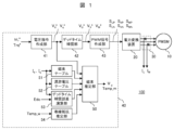
- FIG. 1 is a functional block diagram showing a schematic configuration of a motor drive system according to a first embodiment.
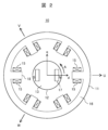
- FIG. 1 is a cross-sectional view in a direction perpendicular to a rotation axis, showing the structure of a permanent magnet synchronous motor 10.
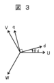
- FIG. 3 is a diagram showing the relationship between the dq axes and the three-phase windings 15 in the stator 11 of the permanent magnet synchronous motor 10.
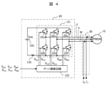
- FIG. FIG. 2 is a circuit diagram showing the configuration of power conversion device 20 (FIG. 1).
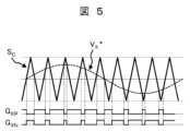
- FIG. 3 is a waveform diagram showing an example of drive signals (G XP , G XN ) (X: any one of U, V, and W).
- 4 is a functional block diagram showing the configuration of a voltage command creation section 41.
- FIG. 1 is a cross-sectional view in a direction perpendicular to a rotation axis, showing the structure of a permanent magnet synchronous motor 10.
- FIG. 3 is a diagram showing the relationship between
- FIG. 2 is a functional block diagram showing the configuration of a magnetic flux estimation unit 50 (FIG. 1) in Example 1.
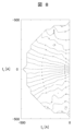
- FIG. This is an example of calculating the q-axis voltage drop V drop_q ′ expressed as an isovalue diagram on the I d - I q plane.
- 9 is a graph showing the relationship between I q and V drop_q shown in FIG. 8 using I d as a parameter.
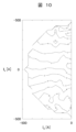
- This is an example of calculating the second q-axis voltage drop V drop_q ′ expressed as an isovalue diagram on the I d - I q plane.
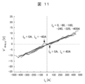
- 11 is a graph showing the relationship between I q and V drop_q ' shown in FIG. 10 using I d as a parameter.
- FIG. 3 is a functional block diagram showing the configuration of a calculation unit for a q-axis voltage drop V drop_q_est in the motor control device 40.
- FIG. FIG. 2 is a functional block diagram showing a schematic configuration of a motor drive system according to a second embodiment.
- 15 is a functional block diagram showing an example of the configuration of a command value correction section 48 (FIG. 14).
- FIG. FIG. 3 is a functional block diagram showing a schematic configuration of a motor control device in a motor drive system according to a third embodiment.
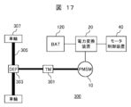
- FIG. 3 is a functional block diagram showing the configuration of an electric vehicle system 300 according to a fourth embodiment.
- FIG. 1 is a functional block diagram showing a schematic configuration of a motor drive system that is Embodiment 1 of the present invention.
- the motor drive system 100 includes a permanent magnet synchronous motor 10, a power conversion device 20, a current sensor 30, and a motor control device 40. Although not shown, a mechanical load is connected to the permanent magnet synchronous motor 10 via a transmission mechanism that mechanically or magnetically transmits the mechanical output of the permanent magnet synchronous motor 10.
- the motor control device 40 controls the rotation speed or torque of the permanent magnet synchronous motor 10 to a desired value by controlling the power conversion device 20. Furthermore, in the first embodiment, the motor control device 40 has a function of estimating the magnetic flux and temperature of the permanent magnets included in the permanent magnet synchronous motor 10, as described later.
- FIG. 2 is a cross-sectional view in a direction perpendicular to the rotation axis, showing the structure of the permanent magnet synchronous motor 10.
- the permanent magnet synchronous motor 10 is composed of a stator 11 and a rotor 12 that face each other with an air gap in between.
- the stator 11 has a plurality of stator magnetic poles 18 each having a winding 15 wound around a stator core 16 made of a magnetic material.
- the rotor 12 has a rotor core 13 made of a magnetic material and a permanent magnet 17 located within the rotor core 13.
- the number of magnetic poles of the stator 11 and rotor 12 is not limited to the number shown in FIG. 2, but can be arbitrarily set according to desired motor characteristics.
- the plurality of windings may be connected in parallel or in series.
- the windings 15 of two opposing stator magnetic poles 18 in the stator 11 are connected in series to form a winding for one phase. Therefore, the stator 11 includes windings for three phases (U, V, W).
- the stator magnetic pole 18 generates a magnetic pole of either north or south polarity by passing a current through the winding 15, and the polarity can be changed depending on the direction of the current in the winding 15.
- the stator magnetic pole 18 becomes an S pole, and when the N pole of the permanent magnet 17 in the rotor 12 is attracted to this S pole, the rotor 12 Let the rotation angle of be zero degrees. Note that, hereinafter, the rotation angle of the rotor 12 will be referred to as "rotor position.”
- the position of any one winding is the reference position.
- the position of the winding 15 (U-phase winding) located on the right side in FIG. 2 is taken as the reference position.
- counterclockwise rotation of the rotor 12 is referred to as normal rotation, and clockwise rotation is referred to as reverse rotation.
- the rotor position is detected by a rotation detector such as a resolver or an encoder, and is used for control processing in the motor control device 40.
- a rotation detector such as a resolver or an encoder
- the rotor position can also be estimated based on the motor current flowing through the permanent magnet synchronous motor 10 or the voltage applied to the permanent magnet synchronous motor 10 without using a rotation detector by applying so-called position sensorless control. good.
- an embedded magnet type permanent magnet synchronous motor 10 is applied, but the rotor is not limited to this, such as a surface magnet type permanent magnet synchronous motor.
- a motor equipped with a permanent magnet whose magnetic flux changes depending on the temperature of the motor may be applied.
- FIG. 3 is a diagram showing the relationship between the dq axes and the three-phase (U, V, W) windings 15 in the stator 11 of the permanent magnet synchronous motor 10.
- the three-phase windings (U, V, W) are arranged with a phase difference of 120 electrical degrees.
- the main magnetic flux direction of the permanent magnets 17 in the rotor 12 is the d-axis, and the direction 90 electrical degrees in the rotational direction from the d-axis is the q-axis.
- the dq axes are coordinate axes in a rotating coordinate system, that is, coordinate axes set on the rotor 12, and rotate together with the rotor 12. Therefore, the rotation angle of the d-axis is equal to the rotor position ( ⁇ d).
- the position of the U-phase winding is used as the reference position, so as shown in FIG. It is expressed as an angle.
- FIG. 4 is a circuit diagram showing the configuration of the power conversion device 20 (FIG. 1).
- FIG. 4 also shows the permanent magnet synchronous motor 10 and the current sensor 30 (FIG. 1).
- the power conversion device 20 includes a DC voltage source 120, a main circuit 131 composed of a three-phase full bridge circuit of semiconductor switching elements 22a to 22f, and a gate drive circuit 123. .
- a shunt resistor 135 is connected between the DC voltage source 120 and the main circuit 131. This prevents excessive current from flowing through the main circuit 131.
- the DC voltage source 120 a battery, an AC/DC converter (including a rectifier), a DC/DC converter, etc. are applied.
- IGBTs are used as the semiconductor switching elements 22a to 22f, but the present invention is not limited to this, and MOSFETs or the like may also be used.
- the main circuit 131 is configured by an inverter module.
- freewheeling diodes are connected in parallel to each of the semiconductor switching elements 22a to 22f, and each parallel connection constitutes an arm.
- the switching elements 22a and 22b constitute the U-phase
- the switching elements 22c and 22d constitute the V-phase
- the switching elements 22e and 22f constitute the W-phase upper and lower arms.
- the connection points of the upper and lower arms of each phase are connected to a permanent magnet synchronous motor 10.
- the gate drive circuit 123 generates drive signals G UP to G WN based on on/off control signals S UP to S WN made up of PWM pulse signals output by the PWM signal generation section 43 (FIG. 1), and generates drive signals G UP to G WN , respectively. It is output to the control terminals (gate terminals in this embodiment) of the semiconductor switching elements 22a to 22f. The semiconductor switching elements 22a to 22f are driven on and off by drive signals G UP to G WN , respectively.
- the main circuit 131 converts the DC voltage Edc of the DC voltage source 120 into a three-phase AC voltage by turning on and off the semiconductor switching elements 22a to 22f, and converts this three-phase AC voltage into a three-phase AC voltage of the permanent magnet synchronous motor 10. Output to three-phase AC terminal.
- FIG. 5 is a waveform diagram showing an example of the drive signals (G XP , G XN ) (X: any one of U, V, and W).
- FIG. 5 also shows an example of the triangular wave carrier signal S C and the X-phase voltage command V X * used by the PWM signal generator 43 (FIG. 1).
- the PWM signal generation unit 43 (FIG. 1) generates an on/off signal consisting of a PWM pulse signal, not shown in FIG. 5, based on the magnitude relationship between the triangular wave carrier signal SC and the X - phase voltage command V Generate control signals S XP and S XN .
- the gate drive circuit 123 In response to the off control signals S XP and S XN , the gate drive circuit 123 generates a drive signal G , G XN .
- the semiconductor switching elements are switched at a frequency sufficiently higher than the frequency of the AC voltage output to the permanent magnet synchronous motor 10. That is, the frequency of the triangular wave carrier signal S C is made sufficiently higher than the frequency of the X-phase voltage command V X * . Therefore, the voltage of each phase output by the main circuit 131 in the power conversion device 20 is a rectangular wave voltage that is pulse width modulated according to the drive signals G XP and G XN , but when averaged over time, the duty It becomes a sinusoidal voltage whose voltage value changes according to the change of the factor.
- Current sensor 30 detects three-phase motor current flowing from power conversion device 20 to permanent magnet synchronous motor 10 .
- the current sensor 30 detects the U-phase motor current IU and the W-phase motor current IW .
- a current transformer (CT) is applied as the current sensor 30, for example.
- a Hall CT or a shunt resistor may be applied.
- a so-called one-shunt method or a three-shunt method is used.
- the DC input current to the main circuit 131 (FIG. 4), that is, the DC bus current
- one shunt resistor for example, the shunt resistor 135 in FIG. 4
- the DC bus current is detected based on the detected value of the DC bus current.
- the three-phase motor current is detected.
- a shunt resistor is provided in each of the three-phase lower arms, and three-phase motor currents are detected based on current values detected by these three shunt resistors.
- Motor control device 40 controls at least one of the speed and torque of permanent magnet synchronous motor 10 by controlling the switching operation of power converter 20 .
- the motor control device 40 provides three-phase voltage commands V U * , V V * , V W * based on the speed command ⁇ r * or the torque command Trq * and the motor current detected by the current sensor 30 .
- the speed command ⁇ r * or the torque command Trq * may be set in the motor control device 40, or may be given to the motor control device 40 from another control system such as a host control system not shown in FIG. It's okay.
- the motor control device 40 uses the PWM signal generation unit 43 to generate on/off control signals S UP to S WN consisting of PWM pulses according to the three-phase voltage commands V U * , V V * , V W * . .
- the motor control device 40 controls the switching operation of the power conversion device 20 using the on/off control signals S UP to S WN .
- the voltage command generation unit 41 (FIG. 1) generates a voltage command value through arithmetic processing in the rotating coordinate system.
- FIG. 6 is a functional block diagram showing the configuration of the voltage command creation section 41.
- the voltage command generation unit 41 generates a first d-axis current command I d * and a first q-axis current command I q * calculated based on the speed command or torque command ( ⁇ r * , Trq * in FIG. 1). , the d-axis detection current I dc , the q-axis detection current I qc , and the inverter frequency command ⁇ 1 ( ⁇ r * may be used instead of ⁇ 1 ), and using equations (1) and (2), Then, a d-axis voltage command V d * and a q-axis voltage command V q * are generated. Note that I dc and I qc are calculated by converting the three-phase motor current detected by the current sensor 30 from a stationary coordinate to a rotating coordinate.
- R is the winding resistance per phase of the permanent magnet synchronous motor 10
- Ld is the d-axis inductance
- Lq is the q-axis inductance
- Ke is the induced voltage constant.
- I d ** and I q ** are second d-axis currents, respectively, generated by a current controller consisting of PI control to cause the motor current to follow I d * and I q * . command and a second q-axis current command.
- the difference (I d * - I dc ) between the first d-axis current command I d * and the d-axis detected current I dc is calculated by the adder / subtractor 91d.
- the calculated difference value is multiplied by a proportional gain (K p_d ) by the proportional device 92c.
- the difference calculation value is multiplied by an integral gain (K i_d ) by a proportional device 92d, and integrated by an integrator 94c.
- the difference calculation value multiplied by the proportional gain K p_d and the integral value multiplied by the integral gain K i_d are added by the adder 90b, and I d ** is calculated.
- the adder/subtractor 91e calculates the difference (I q * - I qc ) between the first q-axis current command I q * and the q-axis detected current I qc .
- the calculated difference value is multiplied by a proportional gain (K p_q ) by the proportional device 92e.
- the difference calculation value is multiplied by an integral gain (K i_q ) by a proportional device 92f, and integrated by an integrator 94d.
- the difference calculation value multiplied by the proportional gain K p_q and the integral value multiplied by the integral gain K i_q are added by the adder 90c, and I q ** is calculated.
- Id ** is multiplied by R by the multiplier 92g, and "R ⁇ Id ** " on the right side of equation (1) is calculated.
- Iq ** is multiplied by R by the multiplier 92i, and "R ⁇ Iq ** " on the right side of equation (2) is calculated.
- I q ** is filtered by the low-pass filter 98a to obtain I q ** _fil shown on the right side of equation (1). Further, I q ** _fil is multiplied by L q and ⁇ 1 by the multiplier 92h, and “ ⁇ 1 ⁇ L q ⁇ I q ** _fil ” on the right side of equation (1) is calculated. The adder/subtractor 91f subtracts " ⁇ 1 ⁇ L q ⁇ I q ** _fil " calculated by the multiplier 92h from "R ⁇ I d ** " calculated by the multiplier 92g. This generates V d * .
- I d ** is filtered by the low-pass filter 98b to obtain I d ** _fil shown on the right side of equation (2). Further, I d ** _fil is multiplied by L d and ⁇ 1 by the multiplier 92j, and “ ⁇ 1 ⁇ L d ⁇ I d ** _fil ” on the right side of equation (2) is calculated. ⁇ 1 is multiplied by Ke by the multiplier 92k, and “ ⁇ 1 ⁇ Ke” in equation (2) is calculated. The adder 90d adds "R ⁇ I q ** " calculated by the multiplier 92i, " ⁇ 1 ⁇ L d ⁇ I d ** _fil " calculated by the multiplier 92j, and the calculated value by the multiplier 92k. and “ ⁇ 1 ⁇ Ke” are added. This generates V q * .
- the d-axis current controller 114a and the q-axis current controller 114b are connected in cascade to the voltage calculation section based on equations (1) and (2).
- FIG. 7 is a functional block diagram showing the configuration of the magnetic flux estimation unit 50 (FIG. 1) in the first embodiment.
- a magnetic flux table 51 a drifting voltage table 52, a dead time compensation error calculation unit 53, and a winding resistance estimation unit 54, which are related to magnetic flux estimation along with the magnetic flux estimation unit 50, are also shown.
- the q-axis voltage command Vq * when a three-phase AC voltage is output from the power converter 20 to the permanent magnet synchronous motor 10, the q-axis voltage command Vq * , the rotational angular velocity ⁇ e (electrical angle) of the permanent magnet synchronous motor 10, Based on the d-axis current I d and the q-axis current I q , the DC voltage Edc of the DC voltage source 120 (FIG. 2), and the winding temperature Temp_w, the d-axis interlinkage magnetic flux ⁇ d representing the magnet magnetic flux and the magnet temperature Temp_m are estimated. be done.
- Equation (4) The q-axis voltage equation in the steady state of the permanent magnet synchronous motor 10 can be expressed by equations (3) and (4) if the differential term (sL q I q ** ) is ignored. Note that ⁇ d0 in Equation (4) is the d-axis interlinkage magnetic flux component caused only by the permanent magnet.
- the q-axis voltage drop V drop_q in equation (3) is the difference (V q * - ⁇ e ⁇ d ) between the speed electromotive force (induced voltage: ⁇ e ⁇ ⁇ d ) and the q-axis voltage command value V q * .
- the total voltage drop on the q-axis including the voltage drop due to the winding resistance R, the voltage drop at the switching elements (Fig. 4: 22a to 22f), the error voltage due to dead time, the error voltage due to the PWM method, etc. be.
- ⁇ d can be estimated by calculating V drop_q in consideration of these multiple voltage components that constitute V drop_q .
- the d-axis current I d and the q-axis current I q are distributed in the form of grid points ((I d , I q )), and (I d , Iq ) and the q-axis voltage ( Vd , Vq ) are measured.
- the magnet temperature Temp_m is set to a constant value ( Temp_m_calib ), for example, a preset standard temperature.
- V q1 * and V q2 * are expressed by the formula ( 3), it can be expressed by the respective equations (5) and (6). Note that ⁇ e2 > ⁇ e1 .
- the q-axis voltage drop V drop_q includes voltage drop components caused by multiple factors. Based on studies by the present inventors, in this embodiment, the q-axis voltage drop component is corrected with respect to the following three factors in order to estimate magnetic flux with high accuracy.
- the three factors are the dead time error time, the resistance component including the winding resistance, and the remainder after removing the voltage drop component caused by the dead time error time and the resistance component from the V drop_q obtained from the q-axis voltage drop adaptation table. is the voltage drop component (drifting voltage).
- V drop_q is expressed by equation (9).
- the first term (RI q ) on the right side of equation (9) is a voltage drop component due to the resistance component R, and is proportional to the d-axis current I d .
- R in equation (9) is the winding resistance of the permanent magnet synchronous motor 10, the resistance component of the semiconductor switching elements (22a to 22f: FIG. 4), and the resistance components from the power converter 20 to the permanent magnet synchronous motor 10, such as wiring cables. (hereinafter referred to as "total resistance value").
- the second term (V dead_q ) on the right side of equation (9) is a voltage drop component that occurs due to dead time compensation.
- the third term (V err_q ) on the right side of equation (9) is called a stray error voltage, and is a nonlinear component of the voltage drop of the semiconductor switching element, a nonlinear component resulting from switching of the semiconductor switching element, and a leakage magnetic flux of the permanent magnet synchronous motor 10. It includes components due to the structure and structure, and is a value unique to the combination of the power converter 20 and the permanent magnet synchronous motor 10.
- V dead_q will be explained below, but first, dead time will be briefly explained.
- dead time is set in the on/off control signals S UP to S WN by the PWM signal generation unit 43 (FIG. 1).
- the dead time compensator 42 converts V d * and V q * into three-phase AC voltage commands V U * , V V * , V W * , and further calculates the dead time In order to reduce the waveform distortion of the motor current caused by this, the dead time error voltage is compensated for V U * , V V * , and V W * .
- dead time compensation that compensates for dead time error voltage.
- the polarity of the three-phase current is determined from the current command on the d and q axes, and the three-phase AC voltage command is corrected based on the three-phase current polarity.
- the dead time compensator 42 of this embodiment calculates the dead time error voltage using a predetermined formula based on the DC power supply voltage, switching frequency, dead time, and current phase of the power conversion device 20.
- the dead time compensation error calculation unit 53 (FIG. 1) in this embodiment calculates a voltage drop component (hereinafter referred to as dead time compensation error voltage) that occurs due to dead time compensation.
- the dead time compensation error calculation unit 53 calculates the dead time compensation error voltage V dead_q appearing on the q-axis using equation (10) and equation (11).
- Edc is the DC voltage of the DC voltage source 120 (FIG. 2)
- T sw is the switching period
- ⁇ is the current phase angle with respect to the d-axis
- T dead_real is the actual dead time.
- T dead_cmp is a dead time compensation time (corresponding to a dead time (set value)).
- the actual dead time T dead_real and the dead time compensation time T dead_cmp are often set to the same value. However, it may have a different value. For example, when the inductance of the motor is small, it may be desirable to suppress distortion of the motor current. In that case, the dead time compensation time is set to a value that minimizes distortion of the motor current. Since the current distortion near the current zero cross tends to increase when the dead time compensation amount is increased, the dead time compensation time is different from the actual dead time time and is sometimes set to a small value. In such a case, a dead time compensation error voltage V dead_q shown in equations (10) and (11) is generated.
- the dead time compensation error voltage V dead_q means an error voltage due to overcompensation or undercompensation when dead time compensation is performed.
- magnetic flux can be estimated with high accuracy even when the actual dead time set by the PWM signal generation unit 43 or the gate drive circuit 123 is different from the dead time compensation time compensated by the dead time compensation unit 42. .
- FIG. 8 is an example of calculation of the q-axis voltage drop V drop_q expressed as an isovalue diagram on the I d -I q plane. Further, FIG. 9 is a graph showing the relationship between I q and V drop_q shown in FIG. 8 using I d as a parameter.
- V drop_q tends to decrease. That is, when I d increases in the negative direction, V drop_q tends to decrease when I q is positive, and V drop_q tends to increase when I q is negative. Furthermore, it can be seen from FIG. 9 that the change in V drop_q with respect to I q differs depending on the value of I d .
- V drop_q is determined by I q without depending on I d .
- the dead time is calculated from the q-axis voltage drop V drop_q as shown in equation (12).
- a second q-axis voltage drop V drop_q ' is defined by subtracting the compensation error voltage V dead_q .
- the dead time compensation error time T dead_calib is changed, and the I d dependence of the second q-axis voltage drop V drop_q ' is minimized.
- T dead_calibb is determined in which a plurality of graphs having I d shown in FIG. 9 as a parameter overlap most.
- the dead time compensation error time T dead_calib is determined so that the total sum of variance is minimized.
- the population mean ⁇ and variance V of the q-axis voltage drop V drop_q at the time of calculating the table data of V drop_q are determined.
- N Id in Equations (13) and (14) is a data group in the I d direction in certain I q data.
- the dispersion corresponds to the variation in V drop_q on the I q -V drop_q plane shown in FIG.
- the dead time compensation error time T dead_calib is changed (for example, every 0.1 ⁇ s) to find the dead time compensation error time at which the sum S is the minimum.
- the second q-axis voltage drop V drop_q ′ when determining T dead_calib is shown in FIGS. 10 and 11.
- FIG. 10 is an example of calculation of the second q-axis voltage drop V drop_q ′ expressed as an isovalue diagram on the I d -I q plane. Further, FIG. 11 is a graph showing the relationship between I q and V drop_q ' shown in FIG. 10 using I d as a parameter.
- the isovalue line of the second q-axis voltage drop Vdrop_q ' is parallel to the d-axis. That is, for a certain I q , the second q-axis voltage drop V drop_q ′ hardly depends on I d and is constant. Moreover, when FIG. 11 and FIG. 9 are compared, a plurality of graphs showing changes in V drop_q ' with respect to I q with I d as a parameter overlap. In this way, the dead time error time T dead_calibb when calculating the table data of V drop_q can be calculated.
- the resistance component R in the above equation (9) is calculated from the slope of the graph shown in FIG. 11 above.
- the average value of V drop_q ' is calculated for each Iq data point, linear approximation is performed on the average value by the method of least squares to find the slope, and the total resistance R when calculating the table data of V drop_q is calculated. Calib .
- total resistance R calib may be calculated using various known optimization calculations.
- Rcalib includes a winding resistance Rw whose resistance value changes depending on the winding temperature Temp_w, a resistance component of a switching element, and a resistance component from the power converter 20 such as a wiring cable to the permanent magnet synchronous motor 10. . Therefore, the winding resistance estimation unit 54 (FIG. 1) sets the winding temperature at the time of calculating the table data of V drop_q as Temp_w _calibb , and sets the winding resistance table data (winding resistance table R w _table) for the winding temperature of the winding resistance R w as Temp_w _calibb. ), a constant resistance component R calibb_const that does not depend on the winding temperature Temp_w_calib at the time of calculating the table data of V drop_q is calculated using equation (16).
- winding resistance R w may be calculated using a known calculation formula.
- a voltage drop component other than the dead time error voltage and the voltage drop due to the resistance component that is, a voltage drop component called a stray voltage will be explained.
- FIG. 12 is an example of calculation of the third q-axis voltage drop V drop_q '' expressed as an isovalue diagram on the I d - I q plane.
- V drop_q '' In calculating V drop_q '', the calculation example of V drop_q shown above (FIG. 8) is used. Therefore, table data (V err_q_calibb_table ) of V drop_q '' with (I d , I q ) as arguments is calculated.
- the table data of V drop_q '' is stored in the motor controller 40 as a stray voltage table 52 (FIGS. 1 and 7).
- V drop_q '' is the remaining voltage drop after removing the dead time compensation error voltage V dead_q and the voltage drop component due to the total resistance R calib (R calib I d ) from the q-axis voltage drop V drop_q . Since it is a component, it has a very small value.
- V drop_q '' is referred to as a stray voltage.
- the stray voltage is related to the leakage magnetic flux and structure of the permanent magnet synchronous motor 10, and has a value unique to the combination of the power converter 20 and the permanent magnet synchronous motor 10. Therefore, the drifting voltage table allows the drifting voltage to be calculated with high accuracy.
- drifting voltage table for each motor control device, it is also possible to create a drifting voltage table for a typical combination of a power converter 20 and a permanent magnet synchronous motor 10 and share it with each motor control device. Good too.
- V drop_q which has been calculated and stored in advance under predetermined operating conditions, is corrected according to the operating conditions (DC voltage Edc, winding temperature, switching frequency, etc.) when the permanent magnet synchronous motor 10 is driven. , a means for calculating the q-axis voltage drop V drop_q_est will be explained.
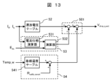
- FIG. 13 is a functional block diagram showing the configuration of a calculation unit for the q-axis voltage drop V drop_q_est in the motor control device 40.
- T w_est is the winding temperature (Temp_w in FIG. 13) when the motor is driven (at the time of magnetic flux estimation), and R calib_const is the constant resistance component of the above-mentioned (Equation (16)).
- R w_table (T w_est ) is table data for the winding temperature of the winding resistance R w described above, and is stored in the winding temperature table 541 (FIG. 13).
- the estimated total resistance R est reflects the dependence of the winding temperature on the value of the voltage drop due to the resistance component.
- Equation (19) corresponds to the right side of Equation (10) above, in which T sw , E dc and ⁇ est are replaced with T sw_est , E dc_est and ⁇ est, respectively.
- V dead_q_calibb differences in operating conditions during driving of the permanent magnet synchronous motor 10 (at the time of estimating magnetic flux) are dynamically reflected in the value of the dead time error voltage.
- the stray voltage table 52 (V err_q_calib_table (I d , I q )) is referred to using the d-axis current I d_est and the q-axis current I q_est when the permanent magnet synchronous motor 10 is driven (at the time of magnetic flux estimation).
- the drifting error voltage V err_q_est when the permanent magnet synchronous motor 10 is driven (at the time of magnetic flux estimation) is calculated using equation (20).
- Equation (21) corresponds to the operation of the calculation unit 501 (FIG. 13).
- the magnetic flux estimating unit 50 (FIG. 7) performs magnetic flux estimation using equation (22).
- V q_est * is the q-axis voltage command when the permanent magnet synchronous motor 10 is driven (at the time of magnetic flux estimation)
- ⁇ e_est is the rotational voltage command when the permanent magnet synchronous motor 10 is driven (at the time of magnetic flux estimation).
- the angular velocity is ⁇ e (electrical angle).
- the right side of Equation (23) indicates that in the table data ⁇ d_calib_table (I d , I q ) in the magnetic flux table 51 (FIG. 1) stored in advance, the arguments (I d , I q ) are (I d_est , I q_est ). It represents the data when .
- the magnetic flux estimation unit 50 calculates the d-axis magnetic flux change amount ⁇ d from the time of calculating the table data of V drop_q when the permanent magnet synchronous motor 10 is driven (at the time of magnetic flux estimation) using equation (24).
- the dq-axis current used for calculation may be a detected current or a current command value.
- the d-axis magnetic flux change amount ⁇ d indicates a change in magnet magnetic flux due to a change in magnet temperature. Since the d-axis inductance (L d ) is almost constant regardless of the magnet temperature, if it is ignored, as shown in equation (25), when controlling the normal d-axis current Id to zero, ⁇ with respect to ⁇ d_calibb The ratio of d_est , that is, the d-axis magnetic flux change rate is calculated. Note that, similarly to equation (24), the magnetic flux table 51 (FIGS. 1 and 7) is referred to.
- the calculated d-axis magnetic flux change rate is input to the magnet temperature estimator 56 (FIG. 7) and compared with a temperature-no-load induced voltage table stored in advance.
- the temperature-no-load induced voltage table is the ratio of the no-load induced voltage at the magnet temperature Temp_m to the no-load induced voltage at the standard temperature when calculating the table data of V drop_q , that is, the no-load induced voltage.
- the relationship between voltage change rate and magnet temperature Temp_m is shown.
- the magnet temperature estimating unit 56 outputs the temperature indicating the no-load induced voltage change rate that matches the d-axis magnetic flux change rate calculated by equation (25) as the estimated magnet temperature Temp_m.
- Voltage drop components are calculated for each generation factor, and the magnetic flux of the permanent magnet is estimated based on these voltage drop components, that is, based on the difference between the voltage command value and the sum of these voltage drop components. This improves the accuracy of magnetic flux estimation.
- the q-axis voltage is calculated from the voltage command for the motor current (I d , I q ) in advance under predetermined operating conditions of the permanent magnet synchronous motor 10 ( ⁇ e1 , ⁇ e2 in the first embodiment).
- the drop V drop_q is calculated and stored in the motor control device 40 as table data using the motor current as an argument. Based on this table data and the calculated value of the voltage drop component due to dead time compensation, table data of the total resistance component and the stray voltage are calculated. Therefore, the number of table data that must be collected by operating the actual machine in advance for magnetic flux estimation can be reduced. Therefore, an increase in the burden of table data creation work can be avoided.
- the stray voltage which is a voltage drop component that is difficult to express in a calculation formula
- table data it can be used under driving conditions where the voltage applied to the permanent magnet synchronous motor is small, such as at low speed or low torque.
- the calculation accuracy of the voltage drop component can be ensured even under the driving conditions. Therefore, the accuracy of magnetic flux estimation and magnet temperature estimation is improved.
- a magnetic flux estimation section 50 a magnetic flux table 51, a drifting voltage table 52, a dead time compensation error calculation section 53, and a winding resistance estimation section 54.
- the magnetic flux estimating device may be independent from the motor control device 40.
- the voltage command and current detected value or current command value
- the magnetic flux estimating device are input to the magnetic flux estimating device via wired or wireless communication.
- a magnetic flux estimating function can be retrofitted to the motor control device.
- the degree of freedom in arranging the motor control device 40 can be increased.
- a voltage command value calculation section that calculates a voltage command value based on a motor torque command, a dead time compensation section that performs dead time compensation based on a voltage command value, and a motor current
- a dead time compensation error calculation section that calculates a dead time compensation error based on the detected value and the DC voltage detection value, a winding resistance calculation section that calculates the electrical resistance value of the winding based on the detected temperature value of the winding, and a motor and a magnetic flux estimator that estimates the magnetic flux of the magnet from the stray voltage, dead time compensation error, and electrical resistance value obtained from the detected current value.
- the motor current and the current flowing through the power converter may increase.
- the speed command and torque command are limited based on the estimated magnet magnetic flux and magnet temperature.
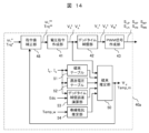
- FIG. 14 is a functional block diagram showing a schematic configuration of a motor drive system that is Embodiment 2 of the present invention. Hereinafter, mainly the points different from the first embodiment will be explained.
- the motor control device 40a in the second embodiment issues a command to correct the speed command ⁇ r * and the torque command Trq * based on the magnet magnetic flux (d-axis interlinkage magnetic flux ⁇ d ) estimated by the magnetic flux estimator 50 or the magnet temperature Temp_m. It has a value correction section 48.
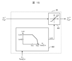
- FIG. 15 is a functional block diagram showing an example of the configuration of the command value correction section 48 (FIG. 14).
- the command value correction section 48 includes a command value restriction section 481 and a limit value calculation section 482.
- the command value limiting unit 481 limits ⁇ r * or Trq * to a limit value Lmt, and the corrected speed command ⁇ r ** or torque command Trq ** .
- the limit value calculation unit 482 compares the magnet magnetic flux (d-axis interlinkage magnetic flux ⁇ d ) or the magnet temperature Temp_m estimated by the magnetic flux estimation unit 50 with the determination threshold value (Th1, Th2: Th1 ⁇ Th2), and calculates the value according to the magnitude relationship. , limit value Lmt is set in the command value limiter 481.
- the limit value Lmt is decreased in a linear or quadratic manner and output. If ⁇ d or Temp_m exceeds the determination threshold Th2, it is determined that the magnet temperature is too high, and the rate of change for decreasing the command limit value is increased.
- the input to the limit value calculation unit 482 may be a reduction rate of the input ⁇ d or Temp_m from a preset reference value.
- the second embodiment described above it is possible to suppress the demagnetization of the permanent magnet and the increase in the current flowing through the permanent magnet synchronous motor and the power converter. Therefore, the reliability of the motor control device and motor drive system is improved.
- FIG. 16 is a functional block diagram showing a schematic configuration of a motor control device 40b in a motor drive system that is Embodiment 3 of the present invention.
- a motor control device 40b in a motor drive system that is Embodiment 3 of the present invention.
- the motor control device 40b includes a protection signal generation section 49.
- the protection signal generation unit 49 compares the value of the magnet magnetic flux (d-axis interlinkage magnetic flux ⁇ d ) or the magnet temperature Temp_m estimated by the magnetic flux estimation unit 50 with a predetermined threshold, and determines whether the value of ⁇ d or Temp_m exceeds the threshold. If it is determined that the voltage is lower than that, a protection signal is output to the outside of the motor control device 40b.
- motor control device 40 may have the functions of such other control devices.
- FIG. 17 is a functional block diagram showing the configuration of an electric vehicle system 300 that is Embodiment 4 of the present invention.
- the motor control device 40 controls AC power supplied from the power conversion device 20 (inverter) to the permanent magnet synchronous motor 10.
- a DC voltage source 120 for example, a battery
- Power converter 20 is controlled by motor control device 40 to convert DC power from DC voltage source 120 into AC power.
- the motor control device 40 any of the motor control devices in the first to third embodiments described above is applied. Therefore, the motor control device 40 has a function of estimating the magnet magnetic flux and magnet temperature of the permanent magnet synchronous motor 10.
- the permanent magnet synchronous motor 10 is mechanically connected to the transmission 301.
- Transmission 301 is mechanically connected to drive shaft 305 via differential gear 303 and supplies mechanical power to wheels 307.
- the wheels 307 are rotationally driven.
- each of the front wheels and the rear wheels may be driven by an independent permanent magnet synchronous motor and a power converter (inverter).
- the accuracy of magnetic flux estimation by the motor control device 40 is improved, so the rotation speed or torque of the permanent magnet synchronous motor 10 can be controlled with high precision. This improves the ride comfort of the electric vehicle system.
- the magnet temperature can be estimated, it is possible to prevent abnormalities in the electric vehicle system 300 due to thermal demagnetization of the permanent magnets of the permanent magnet synchronous motor 10.
- the motor control device 40 can estimate the magnet magnetic flux and magnet temperature using the information of the electric vehicle system 300.
- the winding temperature Temp_w (FIG. 7)
- the ambient temperature near the permanent magnet synchronous motor 10 or the power converter 20 (inverter) can be used.
- a part or all of the above-mentioned configurations, functions, processing units, processing procedures, etc. may be realized in hardware by, for example, designing an integrated circuit.
- each of the configurations and functions described above may be realized by software by having a processor interpret and execute programs for realizing the respective functions.
- signal lines and information lines shown are those considered necessary for the explanation, and do not necessarily show all control lines and information lines.
- the above-mentioned configurations, functions, processing units, processing procedures, etc. do not necessarily need to be located in the same physical location; for example, some of them may be located on a network or cloud via communication.
- the permanent magnet synchronous motor may be either an inner rotor type (FIG. 2) or an outer rotor type, or a radial gap type or an axial gap type.
- SYMBOLS 10 Permanent magnet synchronous motor, 11... Stator, 12... Rotor, 13... Rotor core, 15... Winding, 16... Stator core, 17... Permanent magnet, 18... Stator magnetic pole, 20... Power conversion device , 22a, 22b, 22c, 22d, 22e, 22f... semiconductor switching element, 30... current sensor, 40, 40a, 40b... motor control device, 41... voltage command creation section, 42... dead time compensation section, 43... PWM signal Creation unit, 48... Command value correction unit, 49... Protection signal generation unit, 50... Magnetic flux estimation unit, 51... Magnetic flux table, 52... Drifting voltage table, 53... Dead time compensation error calculation unit, 54... Winding resistance estimation unit , 55... Arithmetic unit, 56...
Landscapes
- Engineering & Computer Science (AREA)
- Power Engineering (AREA)
- Transportation (AREA)
- Mechanical Engineering (AREA)
- Life Sciences & Earth Sciences (AREA)
- Sustainable Development (AREA)
- Sustainable Energy (AREA)
- Control Of Ac Motors In General (AREA)
- Electric Propulsion And Braking For Vehicles (AREA)
Abstract
磁束推定の精度および信頼性を向上できるモータ制御装置が開示される。このモータ制御装置は、回転子が永久磁石を有するモータの速度指令またはトルク指令に応じて、電力変換装置の出力電圧を制御するための電圧指令を生成する電圧指令作成部(41)と、電圧指令に対してデッドタイム補償を行うデッドタイム補償部(42)と、永久磁石の磁束を推定する磁束推定部(50)と、を備え、磁束推定部は、電圧指令と、モータおよび電力変換装置、並びに、モータおよび電力変換装置間に生じる電圧降下と、に基づいて、永久磁石の磁束を推定し、電圧降下は、抵抗成分による第1の電圧降下成分と、デッドタイム補償によって生じる第2の電圧降下成分と、電圧降下から、第1の電圧降下成分および第2の電圧降下成分を除いた第3の電圧降下成分と、を含む。
Description
本発明は、モータ制御装置およびそれを用いた電動車両システムに関する。
永久磁石同期モータは、界磁が永久磁石によって与えられ、高効率化に有利であることから、電動車両などの分野で幅広く適用されている。永久磁石同期モータにおいては、温度などにより永久磁石の磁束量が変動すると、トルク特性などのモータ特性が変動する。このため、適用分野によっては、永久磁石の磁束量を推定し、推定された磁束量に基づいて、永久磁石同期モータが制御される。
永久磁石同期モータの磁束量を推定する従来技術として、特許文献1および特許文献2に記載された技術が知られている。
特許文献1に記載された技術では、基準状態、例えば基準温度状態、からの磁束変化量推定値Δφestが、基準状態におけるd軸電圧Vd_stdおよびq軸電圧Vq_std、d軸補正後電圧指令値Vd**およびq軸補正後電圧指令値Vq**、並びに電気角速度ωによって推定される(Δφest=((Vq**/Vd**)×Vd_std-Vq_std)/ω)。Vd**およびVd**は、それぞれ、d軸電圧指令値Vd*およびq軸電圧指令値Vq*の補正値である。Vd*およびVq*は、インバータにおけるスイッチング素子のデッドタイムTdeadおよびスイッチング素子の直流電圧降下に応じて補正される。Vd*およびVq*のTdeadに応じた補正量は、インバータの直流入力電圧Vdc、スイッチング周波数Fsw、Tdeadおよびd軸基準の電流位相βdに基づいて演算される(段落[0054]参照)。またVd*およびVq*のスイッチング素子の直流電圧降下に応じた補正量は、電流を引数とする電圧降下補正マップにより算出される。
特許文献2に記載された技術では、q軸電圧指令値、d軸電圧指令値、q軸電流、d軸電流および角速度ωに基づいて演算される磁束推定値が、永久磁石同期電動機の動作状態に関する複数のパラメータ、すなわち、角速度、トルク(または電流)、各部の温度(センサ温度、モータ温度、インバータ温度)、インバータの直流電圧の各々を引数とする複数のマップを用いて算出される誤差補正値によって補正される。
特許文献1は、磁束変動量推定値Δφestの算出において、d軸補正後電圧指令値Vd**に対するq軸補正後電圧指令値Vq**の比(Vq**/Vd**)が用いられるので、Vd**が小さい場合には、磁束変動量推定値Δφest自体が増大する。このため、推定値の信頼性に問題がある。
特許文献2は、磁束推定値の演算に用いるq軸電圧指令値およびd軸電圧指令値は補正されない。このため、磁束推定値の精度の向上が制限される。
そこで、本発明は、磁束推定の精度および信頼性を向上できるモータ制御装置、並びにこのモータ制御装置を用いる電動車両システムを提供する。
上記課題を解決するために、本発明によるモータ制御装置は、回転子が永久磁石を有するモータの速度指令またはトルク指令に応じて、モータへの電力変換装置の出力電圧を制御するための電圧指令を生成する電圧指令作成部と、電圧指令に対してデッドタイム補償を行うデッドタイム補償部と、永久磁石の磁束を推定する磁束推定部と、を備えるものであって、磁束推定部は、電圧指令と、モータおよび電力変換装置、並びに、モータおよび電力変換装置間に生じる電圧降下と、に基づいて、永久磁石の磁束を推定し、電圧降下は、モータおよび電力変換装置、並びに、モータおよび電力変換装置間における抵抗成分による第1の電圧降下成分と、デッドタイム補償によって生じる第2の電圧降下成分と、電圧降下から、第1の電圧降下成分および第2の電圧降下成分を除いた第3の電圧降下成分と、を含む。
上記課題を解決するために、本発明による電動車両システムは、車輪と、車輪を駆動するモータと、モータに電力を供給する電力変換装置と、電力変換装置を制御する制御装置と、を備えるものであって、制御装置が、上記本発明によるモータ制御装置である。
本発明によれば、磁束推定の精度および信頼性を向上できる。
上記した以外の課題、構成および効果は、以下の実施形態の説明により明らかにされる。
以下、本発明の実施形態について、下記の実施例1~4により、図面を用いながら説明する。
各図において、参照番号が同一のものは同一の構成要件あるいは類似の機能を備えた構成要件を示している。
図1は、本発明の実施例1であるモータ駆動システムの概略構成を示す機能ブロック図である。
モータ駆動システム100は、永久磁石同期モータ10と、電力変換装置20と、電流センサ30と、モータ制御装置40と、を備えている。永久磁石同期モータ10には、図示はしていないが、永久磁石同期モータ10の機械的出力を機械的あるいは磁気的に伝える伝達機構を介して、機械的負荷が接続される。
モータ制御装置40は、電力変換装置20を制御することによって、永久磁石同期モータ10の回転数またはトルクを所望の値に制御する。また、本実施例1において、モータ制御装置40は、後述するように、永久磁石同期モータ10が備える永久磁石の磁束や温度を推定する機能を有する。
以下、図1に示したモータ駆動システムの各構成要素について説明する。
図2は、永久磁石同期モータ10の構造を示す、回転軸に垂直な方向の断面図である。
永久磁石同期モータ10は、エアギャップを介して対向する固定子11および回転子12から構成されている。固定子11は、磁性体からなる固定子コア16に巻線15が巻かれた固定子磁極18を複数有している。回転子12は、磁性体からなる回転子コア13と、回転子コア13内に位置する永久磁石17とを有している。
本実施例では、図2に示すように、固定子磁極18の個数(=スロット数)が6個、回転子12の磁極数が2個である。なお、固定子11と回転子12の各磁極数は、図2に示す個数に限らず、所望のモータ特性に応じて任意に設定できる。また、複数ある巻線の接続は、並列接続および直列接続のいずれでもよい。本実施例では、固定子11において対向する2個の固定子磁極18の巻線15が直列接続されて、一相分の巻線が構成されている。したがって、固定子11は、三相分の巻線(U,V,W)を備えている。
固定子磁極18は、巻線15に電流を流すことにより、N極およびS極のいずれかの極性の磁極を生じ、巻線15における電流の向きによって極性を変えられる。本実施例では、巻線15に正の直流電流を流すときに固定子磁極18がS極になるとし、このS極に回転子12における永久磁石17のN極が引きつけられるときの回転子12の回転角度をゼロ度とする。なお、以下、回転子12の回転角度を「回転子位置」と表記する。
巻線15が複数ある場合、いずれか一つの巻線の位置を基準位置とする。本実施例では、図2中右側に位置する巻線15(U相巻線)の位置を基準位置とする。また、回転子12の反時計回りの回転を正回転と称し、時計回りの回転を逆回転と称す。
本実施例では、回転子位置は、レゾルバやエンコーダ等の回転検出器によって検出され、モータ制御装置40における制御処理に用いられる。なお、回転子位置は、いわゆる位置センサレス制御を適用して、回転検出器を用いることなく、永久磁石同期モータ10に流れるモータ電流もしくは永久磁石同期モータ10への印加電圧に基づいて推定してもよい。
本実施例では、図2に示すように、埋込磁石型の永久磁石同期モータ10が適用されているが、これに限らず、表面磁石型の永久磁石同期モータなど、回転子が、回転子の温度によって磁束が変化する永久磁石を備えているモータが適用されてもよい。
モータ制御装置40においては、いわゆるベクトル制御が適用されている。そこで、永久磁石同期モータ10と、ベクトル制御に用いられる回転座標軸(d-q軸)との関係について説明しておく。
図3は、d-q軸と、永久磁石同期モータ10の固定子11における三相(U,V,W)の巻線15との関係を示す図である。
図3に示すように、三相の巻線(U,V,W)は、電気角で120度の位相差をもって配置されている。回転子12における永久磁石17の主磁束方向をd軸とし、d軸から回転方向に電気角で90度進んだ方向をq軸とする。
d-q軸は回転座標系における座標軸、すなわち回転子12に設定される座標軸であり、回転子12とともに回転する。したがって、d軸の回転角度は、回転子位置(θd)に等しい。前述のように、本実施例では、U相巻線の位置を基準位置としているので、図3に示すように、θdは、U相巻線の位置から、反時計回りの回転方向を正とする角度で表される。
なお、d軸の方向は、回転子12を回転させるとき、基準位置の巻線15、本実施例ではU相巻線に鎖交する永久磁石17の磁束が最大となる場合に基準位置の巻線の位置に向かう方向でもある。したがって、図3においては、θd=0のときに、U相巻線に鎖交する永久磁石17の磁束が最大となる。
図4は、電力変換装置20(図1)の構成を示す回路図である。図4には、永久磁石同期モータ10および電流センサ30(図1)を併記する。
電力変換装置20は、図4に示すように、直流電圧源120と、半導体スイッチング素子22a~22fの三相フルブリッジ回路から構成される主回路131と、ゲート駆動回路123とを有している。直流電圧源120と主回路131の間には、シャント抵抗135が接続される。これにより、主回路131に過大な電流が流れることが防止される。
直流電圧源120としては、バッテリ、AC/DCコンバータ(整流装置を含む)、DC/DCコンバータなどが適用される。本実施例では、半導体スイッチング素子22a~22fとして、IGBTが適用されるが、これに限らずMOSFETなどを適用してもよい。また、本実施例では、主回路131は、インバータモジュールによって構成されている。
主回路131においては、半導体スイッチング素子22a~22fの各々に環流ダイオードが並列接続され、各並列接続がアームを構成する。2個のアームが、直列に接続されることにより、一相分の上下アームが構成される。本実施例では、図4に示すように、スイッチング素子22a,22bによりU相、スイッチング素子22c,22dによりV相、スイッチング素子22e,22fによりW相の上下アームが構成されている。各相の上下アームの接続点は、永久磁石同期モータ10へ接続されている。
ゲート駆動回路123は、PWM信号作成部43(図1)が出力するPWMパルス信号からなるオン・オフ制御信号SUP~SWNに基づいて、駆動信号GUP~GWNを生成して、それぞれ半導体スイッチング素子22a~22fの制御端子(本実施例では、ゲート端子)に出力する。半導体スイッチング素子22a~22fは、それぞれ、駆動信号GUP~GWNによってオン・オフ駆動される。
主回路131は、半導体スイッチング素子22a~22fがオン・オフ駆動されることにより、直流電圧源120の直流電圧Edcを三相交流電圧に変換し、この三相交流電圧を永久磁石同期モータ10の三相交流端子に出力する。
図5は、駆動信号(GXP,GXN)(X:U,V,Wのいずれか)の一例を示す波形図である。図5には、PWM信号作成部43(図1)が用いる三角波キャリア信号SCとX相電圧指令VX
*の一例が併記されている。
PWM信号作成部43(図1)は、図5に示すように、三角波キャリア信号SCとX相電圧指令VX
*の大小関係から、図5では図示しない、PWMパルス信号からなるオン・オフ制御信号SXP,SXNを生成する。ゲート駆動回路123は、オフ制御信号SXP,SXNに応じて、オフ制御信号SXP,SXNと同じ波形で、かつ半導体スイッチング素子を駆動するために十分な電圧値を有する駆動信号GXP,GXNを生成する。
電力変換装置20においては、永久磁石同期モータ10に出力する交流電圧の周波数よりも充分に高い周波数で半導体スイッチング素子がスイッチングされる。すなわち、三角波キャリア信号SCの周波数がX相電圧指令VX
*の周波数よりも十分に高くされる。このため、電力変換装置20における主回路131が出力する各相の電圧は、駆動信号GXP,GXNに応じてパルス幅変調された矩形波状の電圧であるが、時間的に平均すると、デューティファクタの変化に応じて電圧値が変化する正弦波状電圧になる。
デューティファクタの大きさや、大きさの変化の周期を変えることにより、すなわち、X相電圧指令VX
*の大きさや周波数を変えることにより、電力変換装置20が出力する三相交流電圧の大きさ(振幅)および周波数を制御することができる。これにより、永久磁石同期モータ10の可変速駆動やトルク制御が可能になる。
電流センサ30は、電力変換装置20から永久磁石同期モータ10に流れる三相のモータ電流を検出する。本実施例において、電流センサ30は、U相モータ電流IUおよびW相モータ電流IWを検出する。V相モータ電流(「IV」とする)は、検出されたU相モータ電流IUおよびW相モータ電流IWに基づいて、モータ制御装置40において算出される(IV=-IU-IW)。なお、電流センサ30としては、例えば、電流トランス(CT)が適用される。
電流センサ30としては、ホールCTやシャント抵抗が適用されてもよい。シャント抵抗が適用される場合、いわゆる1シャント方式や3シャント方式が用いられる。1シャント方式では、主回路131(図4)への直流入力電流、すなわち直流母線電流を1個のシャント抵抗(例えば、図4におけるシャント抵抗135)で検出し、直流母線電流の検出値に基づいて、三相モータ電流が検出される。3シャント方式では、三相の下アームの各々にシャント抵抗を設け、これら3個のシャント抵抗によって検出される電流値に基づいて、三相モータ電流が検出される。
次に、モータ制御装置40(図1)について説明する。
モータ制御装置40は、電力変換装置20のスイッチング動作を制御することにより、永久磁石同期モータ10の速度およびトルクの少なくとも一方を制御する。その際、モータ制御装置40は、速度指令ωr
*またはトルク指令Trq*と、電流センサ30によって検出されるモータ電流とに基づいて、三相電圧指令VU
*,VV
*,VW
*を作成する。なお、速度指令ωr
*またはトルク指令Trq*は、モータ制御装置40に設定されていてもよいし、図1には図示されない上位制御系などの他の制御系からモータ制御装置40に与えられてもよい。
さらに、モータ制御装置40は、PWM信号作成部43によって、三相電圧指令VU
*,VV
*,VW
*に応じたPWMパルスからなるオン・オフ制御信号SUP~SWNを生成する。モータ制御装置40は、このオン・オフ制御信号SUP~SWNによって、電力変換装置20のスイッチング動作を制御する。
前述のように、モータ制御装置40においては、いわゆるベクトル制御が適用されている。このため、電圧指令作成部41(図1)は、回転座標系における演算処理により、電圧指令値を生成する。
図6は、電圧指令作成部41の構成を示す機能ブロック図である。
電圧指令作成部41は、速度指令またはトルク指令(図1におけるωr
*,Trq*)に基づいて算出される第1のd軸電流指令Id
*および第1のq軸電流指令Iq
*と、d軸検出電流Idcおよびq軸検出電流Iqcと、インバータ周波数指令ω1(ω1に代えてωr*でもよい)とを入力して、式(1)および式(2)を用いて、d軸電圧指令Vd
*およびq軸電圧指令Vq
*を生成する。なお、IdcおよびIqcは、電流センサ30によって検出される三相モータ電流を、静止座標から回転座標へ座標変換することにより算出される。


式(1)および式(2)において、Rは永久磁石同期モータ10の1相あたりの巻線抵抗、Ldはd軸インダクタンス、Lqはq軸インダクタンス、Keは誘起電圧定数である。
Id
**およびIq
**は、モータ電流がId
*およびIq
*に追従して流れるようにするためにPI制御からなる電流制御器によって生成される、それぞれ第2のd軸電流指令および第2のq軸電流指令である。
Id
**を生成するd軸電流制御器114aにおいては、加減算器91dによって、第1のd軸電流指令Id
*とd軸検出電流Idcとの差分(Id
*-Idc)が演算され、比例器92cによって、差分演算値に、比例ゲイン(Kp_d)が乗算される。また、差分演算値は、比例器92dによって積分ゲイン(Ki_d)が乗算され、積分器94cによって積分される。比例ゲインKp_dが乗算された差分演算値と、積分ゲインKi_dが乗算された積分値とが、加算器90bによって加算され、Id
**が演算される。
Iq
**を生成するq軸電流制御器114bにおいては、加減算器91eによって、第1のq軸電流指令Iq
*とq軸検出電流Iqcとの差分(Iq
*-Iqc)が演算され、比例器92eによって、差分演算値に、比例ゲイン(Kp_q)が乗算される。また、差分演算値は、比例器92fによって積分ゲイン(Ki_q)が乗算され、積分器94dによって積分される。比例ゲインKp_qが乗算された差分演算値と、積分ゲインKi_qが乗算された積分値とが、加算器90cによって加算され、Iq
**が演算される。
Id**には乗算器92gによってRが乗算されて、式(1)の右辺における「R×Id
**」が演算される。Iq**には乗算器92iによってRが乗算されて、式(2)の右辺における「R×Iq
**」が演算される。
Iq
**がローパスフィルタ98aによってフィルタリングされて、式(1)の右辺に示すIq
**
_filが得られる。さらに、Iq
**
_filには乗算器92hによってLqおよびω1が乗算されて、式(1)の右辺における「ω1×Lq×Iq
**
_fil」が演算される。加減算器91fによって、乗算器92gによって演算された「R×Id
**」から、乗算器92hによって演算された「ω1×Lq×Iq
**
_fil」が減算される。これにより、Vd
*が生成される。
Id
**がローパスフィルタ98bによってフィルタリングされて、式(2)の右辺に示すId
**
_filが得られる。さらに、Id
**
_filには乗算器92jによってLdおよびω1が乗算されて、式(2)の右辺における「ω1×Ld×Id
**
_fil」が演算される。ω1には乗算器92kによってKeが乗算されて、式(2)における「ω1×Ke」が演算される。加算器90dによって、乗算器92iによって演算された「R×Iq
**」と、乗算器92jによって演算された「ω1×Ld×Id
**
_fil」と、乗算器92kによって演算された「ω1×Ke」とが加算される。これにより、Vq
*が生成される。
上述のように、電圧指令作成部41では、d軸電流制御器114aおよびq軸電流制御器114bが、式(1)および(2)に基づく電圧演算部にカスケードに接続される。また、電圧演算部には、永久磁石同期モータ10のモータ定数に応じた時定数(Tq(=Lq/R),Td(=Ld/R))を有する一次遅れからなるローパスフィルタ98a,98bが適用されている。これらにより、演算周期に制約がある場合などにおいても、安定したベクトル制御を実現できる。
以下、本実施例1におけるモータ制御装置40が備える磁束推定機能について説明する。
図7は、本実施例1における磁束推定部50(図1)の構成を示す機能ブロック図である。
なお、図7には、磁束推定部50とともに磁束推定に関わる、磁束テーブル51、漂游電圧テーブル52、デッドタイム補償誤差演算部53、巻線抵抗推定部54も併記されている。
本実施例においては、電力変換装置20から永久磁石同期モータ10に三相交流電圧が出力されているとき、q軸電圧指令Vq*、永久磁石同期モータ10の回転角速度ωe(電気角)、d軸電流Idおよびq軸電流Iq、直流電圧源120(図2)の直流電圧Edc、巻線温度Temp_wに基づいて、磁石磁束を表すd軸鎖交磁束Ψd並びに磁石温度Temp_mが推定される。
永久磁石同期モータ10の定常状態におけるq軸電圧方程式は、微分項(sLqIq
**)を無視すると、式(3)および(4)で表せる。なお、式(4)におけるΨd0は、永久磁石のみによるd軸鎖交磁束成分である。


式(3)におけるq軸電圧降下Vdrop_qは、速度起電力(誘起電圧:ωe×Ψd)とq軸電圧指令値Vq
*との差分(Vq
*-ωe×Ψd)であり、巻線抵抗Rによる電圧降下、スイッチング素子(図4:22a~22f)での電圧降下、デッドタイムに起因する誤差電圧、PWM方式に起因する誤差電圧などを含むq軸における総電圧降下である。式(3)に基づけば、Vdrop_qを構成するこれら複数の電圧成分を考慮してVdrop_qを算出することにより、Ψdを推定することができる。
まず、予め、永久磁石同期モータ10の異なる二通りの回転数のもとで、d軸電流Idおよびq軸電流Iqを格子点状((Id,Iq))に振り、(Id,Iq)に対するd軸電圧およびq軸電圧(Vd,Vq)を測定する。この時、磁石温度Temp_mは一定値(Temp_m_calib)、例えば、予め設定される標準温度となるようにする。
永久磁石同期モータ10の回転角速度(電気角)がωe1およびωe2である時のq軸電圧指令値をそれぞれVq1
*およびVq2
*とすると、Vq1
*およびVq2
*は、式(3)に基づいて、それぞれの式(5)および式(6)で表せる。なお、ωe2>ωe1とする。


ここで、d軸鎖交磁束Ψdとq軸電圧降下Vdrop_qは回転数に依存しないとしている。
式(5)および式(6)より、d軸鎖交磁束Ψdおよびq軸電圧降下Vdrop_qは、それぞれ式(7)および式(8)で表される。


上述の測定データ((Id,Iq)に対する(Vd,Vq))を用いて、式(7)および式(8)より、(Id,Iq)を引数とするΨdおよびVdrop_qの各テーブルデータが算出される。ΨdおよびVdrop_qのテーブルデータは、それぞれ、磁束テーブル51(Ψd_calib_table)およびq軸電圧降下適合テーブル(Vdrop_q_calib_table)として、モータ制御装置40に保存される。
q軸電圧降下Vdrop_qは、複数の要因によって生じる電圧降下成分が含まれている。本発明者の検討により、本実施例では、高精度に磁束推定を行うために、次の三要因に関してq軸電圧降下成分を補正する。三要因とは、デッドタイム誤差時間、巻線抵抗を含む抵抗成分、並びに、q軸電圧降下適合テーブルから得られるVdrop_qからデッドタイム誤差時間および抵抗成分を要因とする電圧降下成分を除いた残りの電圧降下成分(漂游電圧)、である。
上記三要因を考慮すると、Vdrop_qは式(9)で表される。

式(9)の右辺第一項(RIq)は、抵抗成分Rによる電圧降下成分であり、d軸電流Idに比例する。式(9)におけるRは、永久磁石同期モータ10の巻線抵抗と、半導体スイッチング素子(22a~22f:図4)の抵抗成分と、配線ケーブルなど、電力変換装置20から永久磁石同期モータ10までの抵抗成分の和である(以下、「総抵抗値」と称する)。式(9)の右辺第二項(Vdead_q)は、デッドタイム補償に伴って生じる電圧降下成分である。式(9)の右辺第三項(Verr_q)は、漂游誤差電圧と称し、半導体スイッチング素子の電圧降下の非線形成分、半導体スイッチング素子のスイッチングに起因する非線形成分、永久磁石同期モータ10の漏れ磁束や構造に起因する成分などを含み、電力変換装置20と永久磁石同期モータ10の組合せによる固有の値になる。
以下、Vdead_qについて説明するが、まず、デッドタイムについて簡単に説明しておく。
前述の図5においては、図示および説明を省略したが、X相上アームの半導体スイッチング素子を駆動する駆動信号GXPと、X相下アームの半導体スイッチング素子を駆動する駆動信号GXNには、上下アームの短絡を防止するために、両アームの半導体スイッチング素子が共にオフとなる期間、すなわち、いわゆるデッドタイムが設定される。
なお、本実施例では、PWM信号作成部43(図1)によって、オン・オフ制御信号SUP~SWNにデッドタイムが設定される。
デッドタイムが設定されていると、永久磁石同期モータ10に印加したい電圧(電圧指令)と、実際に永久磁石同期モータ10に印加される電圧との間に誤差(デッドタイム誤差電圧)が生じる。このため、モータ電流の波形歪が発生する。そこで、本実施例では、デッドタイム補償部42(図1)が、Vd
*およびVq
*を三相交流電圧指令VU
*,VV
*,VW
*に変換し、さらに、デッドタイムに伴うモータ電流の波形歪を低減するために、VU
*,VV
*,VW
*に対してデッドタイム誤差電圧を補償する。
なお、デッドタイム誤差電圧を補償するデッドタイム補償に関しては様々な技術が知られている。例えば、dq軸における電流指令から三相電流の極性を求め、この三相電流極性により三相交流電圧指令を補正する。
本実施例のデッドタイム補償部42では、電力変換装置20の直流電源電圧、スイッチング周波数、デッドタイムおよび電流位相に基づき、所定の数式を用いて、デッドタイム誤差電圧を演算する。
本実施例におけるデッドタイム補償誤差演算部53(図1)は、デッドタイム補償に伴って発生する電圧降下成分(以下、デッドタイム補償誤差電圧と称す)を演算する。
デッドタイム補償誤差演算部53は、q軸に現れるデッドタイム補償誤差電圧Vdead_qを、式(10)および式(11)によって演算する。


式(10)および式(11)において、Edcは直流電圧源120(図2)の直流電圧、Tswはスイッチング周期、βはd軸を基準とする電流位相角、Tdead_realは実際のデッドタイム、Tdead_cmpはデッドタイム補償時間(デッドタイム(設定値)に相当)である。
実際のデッドタイムTdead_realと、デッドタイム補償時間Tdead_cmpは、同じ値にすることが多い。しかし、異なる値にすることもある。例えば、モータのインダクタンスが小さい時などは、モータ電流の歪を抑制したい場合がある。その場合、デッドタイム補償時間は、モータ電流の歪を最小化する値に設定する。電流ゼロクロス付近の電流歪は、デッドタイム補償量を大きくすると増大しやすいため、デッドタイム補償時間は実際のデッドタイム時間とは異なり、小さい値に設定されることがある。このような場合、式(10)および式(11)に示すデッドタイム補償誤差電圧Vdead_qが発生する。デッドタイム補償誤差電圧Vdead_qは、デッドタイム補償を行った際の過補償あるいは補償不足による誤差電圧を意味する。
本実施例においては、PWM信号作成部43やゲート駆動回路123で設定される実際のデッドタイムと、デッドタイム補償部42で補償するデッドタイム補償時間が異なる場合においても高精度に磁束推定ができる。
ここで、q軸電圧降下Vdrop_qの算出例について、図8および図9を用いて説明する。
図8は、Id-Iq平面に等値線図として表したq軸電圧降下Vdrop_qの算出例である。また、図9は、図8に示すIqとVdrop_qの関係を、Idをパラメータとして表したグラフである。
図8により、あるIqに対してIdが負方向に大きくなるにつ入れて、Vdrop_qの絶対値が減少する傾向にあるのが分かる。つまり、Idが負方向に大きくなると、Iqが正ではVdrop_qが減少、Iqが負ではVdrop_qが増加する傾向がある。また、図9からも、Idの値に応じて、Iqに対するVdrop_qの変化が異なっているのが分かる。
式(10)および式(11)に基づけば、Iqに対するVdrop_qの変化が異なっているのは、電流位相角βの関数であるデッドタイム補償誤差電圧Vdead_qが存在するためである。一方、実際のデッドタイムとデッドタイム補償時間が同じである場合、q軸電圧降下Vdrop_qは、式(9)の右辺第一項の抵抗成分Rによる電圧降下成分が支配的な成分となる。この場合、Idに依存することなくIqによってVdrop_qの値が決まる。
上述のように予め算出されてテーブルデータとして保存されているq軸電圧降下Vdrop_qから、デッドタイム誤差時間の算出のため、式(12)に示すように、q軸電圧降下Vdrop_qからデッドタイム補償誤差電圧Vdead_qを減じた第二のq軸電圧降下Vdrop_q’を定義する。

Vdrop_qのテーブルデータ算出時におけるデッドタイム誤差時間を算出するために、デッドタイム補償誤差時間Tdead_calibを変化させていき、第二のq軸電圧降下Vdrop_q’のId依存性が最も小さくなるデッドタイム補償誤差時間Tdead_calibを求める。これは、言いかえると、図9に示すIdをパラメータとする複数のグラフが最も重なる状態となるTdead_calibを求めることになる。このとき、公知の種々の最適化計算を用いることも可能であるが、本実施例では分散の総和が最小になるように、デッドタイム補償誤差時間Tdead_calibを求める。次の式(13)および式(14)のように、Vdrop_qのテーブルデータ算出時におけるq軸電圧降下Vdrop_qの母平均μおよび分散Vを求める。


式(13)および式(14)におけるNIdは、あるIqデータにおけるId方向のデータ群である。分散は、図9に示すIq-Vdrop_q平面におけるVdrop_qのバラつきに相当する。
さらに、各Iqデータ点における第二のq軸電圧降下Vdrop_q’の分散の総和Sを式(15)により求める。

式(15)で表される総和Sが最小になる時、第二のq軸電圧降下Vdrop_q’のIdに対する依存性(バラつき)が小さくなるとして、デッドタイム補償誤差時間Tdead_calibを求める。
図8および図9に示したq軸電圧降下Vdrop_qの測定例において、デッドタイム補償誤差時間Tdead_calibを変化させ(例えば、0.1μs毎など)、総和Sが最小になるデッドタイム補償誤差時間Tdead_calibを求めた際の第二のq軸電圧降下Vdrop_q’を図10および図11に示す。
図10は、Id-Iq平面に等値線図として表した第二のq軸電圧降下Vdrop_q’の算出例である。また、図11は、図10に示すIqとVdrop_q’の関係を、Idをパラメータとして表したグラフである。
図10と図8を比較すると、第二のq軸電圧降下Vdrop_q’の等値線がd軸に対し平行になっている。つまり、あるIqに対し、第二のq軸電圧降下Vdrop_q’はIdにほとんど依存せず、一定となっている。また、図11と図9を比較すると、Idをパラメータとする、Iqに対するVdrop_q’の変化を示す複数のグラフが重なっている。このようにして、Vdrop_qのテーブルデータ算出時におけるデッドタイム誤差時間Tdead_calibを算出することができる。
次に、抵抗成分による電圧降下成分について説明する。
本実施例では、前述の図11のグラフの傾きから、前述の式(9)における抵抗成分Rが算出される。本実施例では、Iqデータ点毎にVdrop_q’の平均値を算出し、平均値に対して最小二乗法による線形近似を行って傾きを求め、Vdrop_qのテーブルデータ算出時における総抵抗Rcalibとする。
なお、公知の種々の最適化計算を用いて、総抵抗Rcalibを算出してもよい。
Rcalibには、巻線温度Temp_wによって抵抗値が変化する巻線抵抗Rwと、スイッチング素子の抵抗成分と、配線ケーブルなど電力変換装置20から永久磁石同期モータ10までの抵抗成分とが含まれる。そこで、巻線抵抗推定部54(図1)は、Vdrop_qのテーブルデータ算出時における巻線温度をTemp_w_calibとし、巻線抵抗Rwの巻線温度に対するテーブルデータ(巻線抵抗テーブルRw_table)を用いて、Vdrop_qのテーブルデータ算出時における巻線温度Temp_w_calibに依存しない定抵抗成分Rcalib_constを式(16)で算出する。

なお、巻線抵抗Rwは、公知の計算式で算出されてもよい。
次に、デッドタイム誤差電圧および抵抗成分による電圧降下以外の電圧降下成分、すなわち漂游電圧と称する電圧降下成分について説明する。
Vdrop_qのテーブルデータ算出時におけるq軸電圧降下Vdrop_qから、デッドタイム補償誤差電圧Vdead_qと総抵抗Rcalibによる電圧降下成分を除いた残りの電圧降下成分を、第三のq軸電圧降下Vdrop_q’’として、式(17)で定義する。なお、式(17)の右辺第一項のVdrop_q’は、前述の第二のq軸電圧降下(式(12))である。

図12は、Id-Iq平面に等値線図として表した第三のq軸電圧降下Vdrop_q’’の算出例である。
Vdrop_q’’の算出においては、前述(図8)に示したVdrop_qの算出例が用いられている。したがって、(Id,Iq)を引数とするVdrop_q’’のテーブルデータ(Verr_q_calib_table)が算出される。Vdrop_q’’のテーブルデータは、漂游電圧テーブル52(図1,7)として、モータ制御装置40に保存される。
図12から分かるように、Vdrop_q’’は、q軸電圧降下Vdrop_qから、デッドタイム補償誤差電圧Vdead_qと総抵抗Rcalibによる電圧降下成分(RcalibId)を除いた残りの電圧降下成分であるため、非常に小さい値となっている。
本発明者の検討によれば、Vdrop_q’’は、具体的要因を特定して計算式で表すことが難しい。そこで、本実施例では、Vdrop_q’’を漂游電圧と称している。
本発明者の検討によれば、漂游電圧は、永久磁石同期モータ10の漏れ磁束や構造が関わっており、電力変換装置20と永久磁石同期モータ10の組合せによる固有の値になる。したがって、漂游電圧テーブルにより、精度よく漂游電圧を算出することができる。
なお、漂游電圧テーブルは、モータ制御装置毎に作成することが好ましいが、代表的な電力変換装置20と永久磁石同期モータ10の組合せについて漂游電圧テーブルを作成し、各モータ制御装置において共用してもよい。
次に、予め所定の動作条件で算出されて保存されているVdrop_qを、永久磁石同期モータ10の駆動時の動作条件(直流電圧Edc、巻線温度、スイッチング周波数など)に応じて補正して、q軸電圧降下Vdrop_q_estを算出する手段について説明する。
図13は、モータ制御装置40におけるq軸電圧降下Vdrop_q_estの演算部の構成を示す機能ブロック図である。
永久磁石同期モータ10の駆動時における総抵抗Restは、式(18)により算出される。

式(18)において、Tw_estはモータ駆動時(磁束推定時)の巻線温度(図13中ではTemp_w)であり、Rcalib_constは前述(式(16))の定抵抗成分である。Rw_table(Tw_est)は、前述した、巻線抵抗Rwの巻線温度に対するテーブルデータであり、巻線温度テーブル541(図13)に格納されている。
推定総抵抗Restにより、巻線温度の依存性が抵抗成分による電圧降下の値に反映される。
次に、永久磁石同期モータ10の駆動時(磁束推定時)における、スイッチング周期Tsw_est、直流電圧Edc_estおよび電流位相角βestを用いて、永久磁石同期モータ10の駆動時(磁束推定時)におけるデッドタイム補償誤差電圧Vdead_q_calibを式(19)により算出する。電流位相角βestは、電流位相演算器531(図13)によって、Id,Iqに基づいて演算される。式(19)による演算は、演算部532の動作に相当する。

なお、式(19)は、前述の式(10)の右辺において、Tsw、Edcおよびβestを、それぞれ、Tsw_est、Edc_estおよびβestに置き換えたものに相当する。
Vdead_q_calibにより、永久磁石同期モータ10の駆動時(磁束推定時)における動作条件の違いを、動的にデッドタイム誤差電圧の値に反映される。
さらに、永久磁石同期モータ10の駆動時(磁束推定時)における、d軸電流Id_estおよびq軸電流Iq_estを用いて、漂游電圧テーブル52(Verr_q_calib_table(Id,Iq))を参照することで、永久磁石同期モータ10の駆動時(磁束推定時)における漂游誤差電圧Verr_q_estを式(20)により算出する。

上述のRest,Vdead_q_calib,Verr_q_estを用いて、永久磁石同期モータ10の駆動時(磁束推定時)におけるq軸電圧降下Vdrop_q_estが式(21)により算出される。

式(21)による演算は、演算部501(図13)の動作に相当する。
上述のように要因別に算出された複数の電圧降下成分からなるq軸電圧降下に基づいて、磁束推定部50(図7)は、式(22)により磁束推定を行う。

式(22)において、Vq_est
*は永久磁石同期モータ10の駆動時(磁束推定時)におけるq軸電圧指令であり、ωe_estは、永久磁石同期モータ10の駆動時(磁束推定時)における回転角速度ωe(電気角)である。
なお、式(22)による演算は、磁束推定部50(図7)における演算部55の動作に相当する。
さらに、磁束推定部50は、Id_est,Iq_estを用いて、同一電流条件(Id=Id_est,Iq=Iq_est)における、Vdrop_qのテーブルデータ算出時における磁束Ψd_calibを、式(23)により算出する。式(23)の右辺は、予め保存されている磁束テーブル51(図1)におけるテーブルデータΨd_calib_table(Id,Iq)において、引数(Id,Iq)が(Id_est,Iq_est)である場合のデータを表している。

さらに、磁束推定部50は、永久磁石同期モータ10の駆動時(磁束推定時)におけるVdrop_qのテーブルデータ算出時からのd軸磁束変化量ΔΨdを、式(24)により算出する。なお、算出に用いるdq軸電流は、検出電流でも電流指令値でも構わない。

d軸磁束変化量ΔΨdは、磁石温度の変動に伴う磁石磁束の変化を示している。d軸インダクタンス(Ld)は磁石温度に寄らずほぼ一定であるため無視すると、式(25)のように、通常のd軸電流Idをゼロになるように制御する場合における、Ψd_calibに対するΨd_estの比率、すなわちd軸磁束変化率を算出する。なお、式(24)と同様に、磁束テーブル51(図1,7)が参照されている。
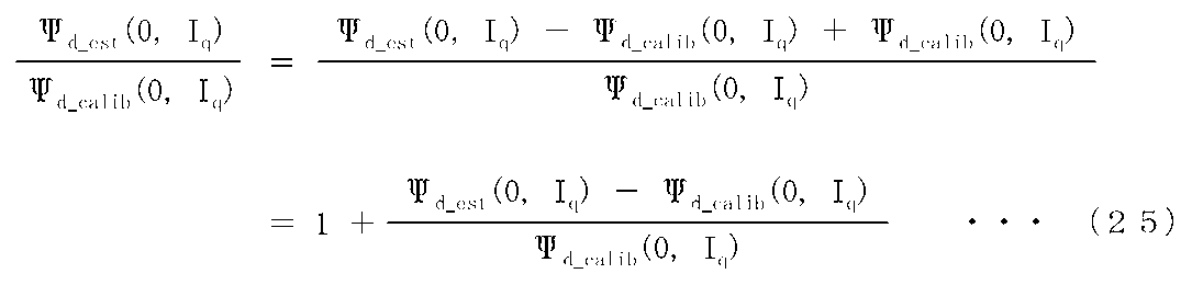
なお、式(25)の右辺における分数部分の分母は、式(24)により算出されたd軸磁束変化量ΔΨdに相当する。
算出したd軸磁束変化率は、磁石温度推定部56(図7)に入力され、予め保存されている、温度-無負荷誘起電圧テーブルと比較される。なお、本実施例では、温度-無負荷誘起電圧テーブルは、Vdrop_qのテーブルデータ算出時における標準温度における無負荷誘起電圧に対する、磁石温度Temp_mの時の無負荷誘起電圧の比率、すなわち無負荷誘起電圧変化率と、磁石温度Temp_mとの関係を示す。
磁石温度推定部56は、比較の結果、式(25)により算出されたd軸磁束変化率と一致する無負荷誘起電圧変化率を示す温度を推定磁石温度Temp_mとして出力する。
上述した実施例1によれば、永久磁石同期モータ10および電力変換装置間の配線や半導体スイッチング素子の抵抗を含む総抵抗成分による電圧降下成分、デッドタイム補償による電圧降下成分、漂游電圧による電圧降下成分という、発生要因別に電圧降下成分を算出し、これらの電圧降下成分に基づいて、すなわち電圧指令値と、これら電圧降下成分の総和との差に基づいて、永久磁石の磁束を推定する。これにより、磁束推定の精度が向上する。
また、実施例1においては、予め、永久磁石同期モータ10の所定の動作条件(実施例1では、ωe1,ωe2)で、モータ電流(Id,Iq)に対する電圧指令からq軸電圧降下Vdrop_qを算出し、モータ電流を引数とするテーブルデータとしてモータ制御装置40に保存される。このテーブルデータと、デッドタイム補償による電圧降下成分の算出値とに基づいて、総抵抗成分と、漂游電圧のテーブルデータが算出される。したがって、磁束推定のために、予め実機を運転してデータの収集を要するテーブルデータの数が低減できる。このため、テーブルデータ作成作業の負担増加が避けられる。
また、計算式で表すことが難しい電圧降下成分である漂游電圧をテーブルデータとして予め保存しておくことにより、永久磁石同期モータに印加する電圧が小さくなる駆動条件の場合、例えば低速または低トルクの駆動条件においても、電圧降下成分の算出精度を確保できる。このため、磁束推定および磁石温度の推定精度が向上する。
本実施例1では、図1に示すように、磁束推定に関わる機能構成部、すなわち磁束推定部50、磁束テーブル51、漂游電圧テーブル52、デッドタイム補償誤差演算部53および巻線抵抗推定部54がモータ制御装置40に内蔵されているが、このような形態に限らず、磁束推定装置としてモータ制御装置40とは独立した形態としてもよい。この場合、電圧指令や電流検出値(または電流指令値)は、有線もしくは無線通信を介して、磁束推定装置に入力される。これにより、モータ制御装置に、磁束推定機能を、後付けすることができる。また、モータ制御装置40の配置の自由度を高めることができる。
また、本実施例では、上述のように、モータのトルク指令に基づき電圧指令値を演算する電圧指令値演算部と、電圧指令値に基づきデッドタイム補償を行うデッドタイム補償部と、モータの電流検出値と直流電圧検出値に基づきデッドタイム補償誤差を演算するデッドタイム補償誤差算出部と、巻線の温度検出値に基づき、巻線の電気抵抗値を演算する巻線抵抗演算部と、モータの電流検出値から求められる漂遊電圧とデッドタイム補償誤差と電気抵抗値とから磁石の磁束を推定する磁束推定部と、を備える。これにより、磁束推定を行う際に用いる電圧情報自体の誤差を低減し、磁束推定精度を高めることができる。
永久磁石同期モータに用いられる永久磁石においては、永久磁石の温度が上昇すると、減磁が発生し、回転速度やトルクの制御が難しくなる。また、永久磁石同期モータが発生するトルクを確保するために、モータ電流や、電力変換装置に流れる電流が、増加する場合もある。
そこで、本実施例2においては、推定された磁石磁束や磁石温度に基づいて、速度指令や、トルク指令を制限する。
図14は、本発明の実施例2であるモータ駆動システムの概略構成を示す機能ブロック図である。以下、主に、実施例1と異なる点について説明する。
本実施例2におけるモータ制御装置40aは、速度指令ωr
*やトルク指令Trq*を磁束推定部50が推定した磁石磁束(d軸鎖交磁束Ψd)または磁石温度Temp_mに基づいて補正する指令値補正部48を有している。
図15は、指令値補正部48(図14)の一構成例を示す機能ブロック図である。
指令値補正部48は、指令値制限部481および制限値演算部482を備えている。
指令値制限部481は、入力した速度指令ωr
*やトルク指令Trq*が所定値を越えたら、ωr
*やTrq*を制限値Lmtに制限して、補正された速度指令ωr
**やトルク指令Trq**として出力する。
制限値演算部482は、磁束推定部50が推定した磁石磁束(d軸鎖交磁束Ψd)または磁石温度Temp_mと判定閾値(Th1,Th2:Th1<Th2)と比較し、大小関係に応じて、制限値Lmtを指令値制限部481に設定する。
本実施例2では、図15に示すように、ΨdまたはTemp_mが判定閾値Th1を超えたら、1次関数または2次関数的に制限値Lmtを減少させて出力する。ΨdまたはTemp_mが判定閾値Th2を超えたら、磁石温度が高温になり過ぎていると判断し、指令リミット値を減少させる変化率をより大きくする。
なお、制限値演算部482への入力は、入力されたΨdまたはTemp_mの予め設定した基準値からの減少率としても良い。
上述の実施例2によれば、永久磁石の減磁や、永久磁石同期モータや電力変換装置に流れる電流の増加を抑制することができる。したがって、モータ制御装置やモータ駆動システムの信頼性が向上する。
なお、速度指令やトルク指令に代えて、電流指令を調整してもよい。
図16は、本発明の実施例3であるモータ駆動システムにおけるモータ制御装置40bの概略構成を示す機能ブロック図である。以下、主に、実施例2と異なる点について説明する。
本実施例3では、モータ制御装置40bが、保護信号生成部49を有している。
保護信号生成部49は、磁束推定部50が推定した磁石磁束(d軸鎖交磁束Ψd)または磁石温度Temp_mの値を所定の閾値と比較し、ΨdまたはTemp_mの値が閾値を超えたり下回ったりしたと判定すると、保護信号をモータ制御装置40bの外部へ出力する。
図示しない他の制御装置が、保護信号を受信すると、永久磁石同期モータ10の速度指令またはトルク指令を減少させたり、永久磁石同期モータ10を停止させたりする。これにより、モータ駆動システム(図1の100)の信頼性が向上する。
なお、このような他の制御装置の機能は、モータ制御装置40が備えていてもよい。
図17は、本発明の実施例4である電動車両システム300の構成を示す機能ブロック図である。
モータ制御装置40は、電力変換装置20(インバータ)から永久磁石同期モータ10に供給する交流電力を制御する。直流電圧源120(例えばバッテリ)は、電力変換装置20(インバータ)に直流電力を供給する。電力変換装置20(インバータ)は、モータ制御装置40によって制御されることにより、直流電圧源120からの直流電力を交流電力に変換する。モータ制御装置40として、前述の実施例1~3の内のいずれかのモータ制御装置が適用される。したがって、モータ制御装置40は、永久磁石同期モータ10の磁石磁束および磁石温度を推定する機能を有する。
永久磁石同期モータ10は、トランスミッション301に機械的に接続される。トランスミッション301は、ディファレンシャルギア303を介してドライブシャフト305に機械的に接続され、車輪307に機械的動力を供給する。これにより、車輪307が回転駆動される。
なお、永久磁石同期モータ10が、トランスミッション301を介さず、直接、ディファレンシャルギア303に接続されてもよい。また、自動車の場合、前輪および後輪の各々が独立した永久磁石同期モータおよび電力変換装置(インバータ)によって駆動されてもよい。
本実施例によれば、モータ制御装置40による磁束推定の精度が向上するので、永久磁石同期モータ10の回転数またはトルクを高精度に制御できる。これにより、電動車両システムの乗り心地が向上する。
また、本実施例によれば、磁石温度を推定することができるので、永久磁石同期モータ10の永久磁石の熱減磁などにともなう、電動車両システム300の異常発生を防止することができる。
また、本実施例によれば、モータ制御装置40は、電動車両システム300の情報を用いて、磁石磁束および磁石温度を推定できる。例えば、巻線温度Temp_w(図7)の代わりに、永久磁石同期モータ10や電力変換装置20(インバータ)付近の雰囲気温度を用いることができる。
なお、本発明は前述した実施形態に限定されるものではなく、様々な変形例が含まれる。例えば、前述した実施例は本発明を分かりやすく説明するために詳細に説明したものであり、必ずしも説明した全ての構成を備えるものに限定されるものではない。また、各実施形態の構成の一部について、他の構成の追加・削除・置き換えをすることが可能である。
例えば、上記の各構成、機能、処理部、処理手続き等は、それらの一部または全部を、例えば集積回路で設計する等によりハードウェアで実現しても良い。また、上記の各構成や機能等は、プロセッサがそれぞれの機能を実現するプログラムを解釈し、実行することによりソフトウェアで実現しても良い。
また、信号線や情報線は説明上必要と考えられるものを示しており、必ずしも全ての制御線や情報線を示しているとは限らない。また、上記の各構成、機能、処理部、処理手続き等は、必ずしも物理的に同じ場所にある必要は無く、例えば、一部が通信などを介してネットワーク上やクラウド上にあっても良い。
また、永久磁石同期モータは、内転型(図2)および外転型のいずれでもよいし、ラジアルギャップ型およびアキシャルギャップ型のいずれでもよい。
10…永久磁石同期モータ、11…固定子、12…回転子、13…回転子コア、15…巻線、16…固定子コア、17…永久磁石、18…固定子磁極、20…電力変換装置、22a,22b,22c,22d,22e,22f…半導体スイッチング素子、30…電流センサ、40,40a,40b…モータ制御装置、41…電圧指令作成部、42…デッドタイム補償部、43…PWM信号作成部、48…指令値補正部、49…保護信号生成部、50…磁束推定部、51…磁束テーブル、52…漂游電圧テーブル、53…デッドタイム補償誤差演算部、54…巻線抵抗推定部、55…演算部、56…磁石温度推定部、90b,90c,90d…加算器、91d,91e,91f…加減算器、92c,92d,92e,92f…比例器、92g,92h,92i,92j,92k…乗算器、94c,94d…積分器、98a,98b…ローパスフィルタ、100…モータ駆動システム、114a…d軸電流制御器、114b…q軸電流制御器、120…直流電圧源、123…ゲート駆動回路、131…主回路、135…シャント抵抗、300…電動車両システム、301…トランスミッション、303…ディファレンシャルギア、305…ドライブシャフト、307…車輪、481…指令値制限部、482…制限値演算部、501…演算部、531…電流位相演算器、532…演算部、541…巻線温度テーブル、
Claims (11)
- 回転子が永久磁石を有するモータの速度指令またはトルク指令に応じて、前記モータへの電力変換装置の出力電圧を制御するための電圧指令を生成する電圧指令作成部と、
前記電圧指令に対してデッドタイム補償を行うデッドタイム補償部と、
前記永久磁石の磁束を推定する磁束推定部と、
を備えるモータ制御装置において、
前記磁束推定部は、
前記電圧指令と、前記モータおよび前記電力変換装置、並びに、前記モータおよび前記電力変換装置間に生じる電圧降下と、に基づいて、前記永久磁石の磁束を推定し、
前記電圧降下は、
前記モータおよび前記電力変換装置、並びに、前記モータおよび前記電力変換装置間における抵抗成分による第1の電圧降下成分と、
前記デッドタイム補償によって生じる第2の電圧降下成分と、
前記電圧降下から、前記第1の電圧降下成分および前記第2の電圧降下成分を除いた第3の電圧降下成分と、
を含むことを特徴とするモータ制御装置。 - 請求項1に記載のモータ制御装置において、
前記モータの所定回転速度における、前記電圧降下とモータ電流との関係を示すテーブルデータを有し、
前記テーブルデータと前記第2の電圧降下成分とに基づいて、前記抵抗成分を演算することを特徴とするモータ制御装置。 - 請求項1に記載のモータ制御装置において、
スイッチング周期と、前記電力変換装置が備える直流電圧源の直流電圧と、電流位相角とに基づいて、前記第2の電圧降下成分を演算することを特徴とするモータ制御装置。 - 請求項1に記載のモータ制御装置において、
前記モータの所定回転速度における、前記電圧降下とモータ電流との関係を示す第1のテーブルデータを有し、
前記テーブルデータと前記第2の電圧降下成分とに基づいて、前記第3の電圧降下成分とモータ電流との関係を表す第2のテーブルデータを演算し、
前記第2のテーブルデータに基づいて前記第3の電圧降下成分を演算することを特徴とするモータ制御装置。 - 請求項1に記載のモータ制御装置において、
前記磁束推定部は、推定した前記磁束に基づいて、前記永久磁石の温度を推定することを特徴とするモータ制御装置。 - 請求項1に記載のモータ制御装置において、
前記磁束推定部が推定した前記磁束に基づいて、前記速度指令または前記トルク指令を調整することを特徴とするモータ制御装置。 - 請求項5に記載のモータ制御装置において、
前記磁束推定部が推定した前記温度に基づいて、前記速度指令または前記トルク指令を調整することを特徴とするモータ制御装置。 - 請求項6または請求項7に記載のモータ制御装置において、
前記速度指令または前記トルク指令が所定のしきい値を超えたら、前記速度指令または前記トルク指令を所定値に制限することを特徴とするモータ制御装置。 - 請求項1に記載のモータ制御装置において、
前記磁束推定部が推定した前記磁束が所定値を超えるかもしくは下回った場合に、外部へ信号を発することを特徴とするモータ制御装置。 - 請求項5に記載のモータ制御装置において、
前記磁束推定部が推定した前記温度が所定値を超えるかもしくは下回った場合に、外部へ信号を発することを特徴とするモータ制御装置。 - 車輪と、
車輪を駆動するモータと、
前記モータに電力を供給する電力変換装置と、
前記電力変換装置を制御する制御装置と、
を備える電動車両システムにおいて、
前記制御装置が、請求項1または請求項5に記載のモータ制御装置であることを特徴とする電動車両システム。
Priority Applications (1)
| Application Number | Priority Date | Filing Date | Title |
|---|---|---|---|
| DE112023001855.3T DE112023001855T5 (de) | 2022-08-08 | 2023-06-16 | Motorsteuerungseinrichtung und elektrofahrzeugsystem |
Applications Claiming Priority (2)
| Application Number | Priority Date | Filing Date | Title |
|---|---|---|---|
| JP2022-126150 | 2022-08-08 | ||
| JP2022126150A JP7813675B2 (ja) | 2022-08-08 | 2022-08-08 | モータ制御装置並びに電動車両システム |
Publications (1)
| Publication Number | Publication Date |
|---|---|
| WO2024034259A1 true WO2024034259A1 (ja) | 2024-02-15 |
Family
ID=89851348
Family Applications (1)
| Application Number | Title | Priority Date | Filing Date |
|---|---|---|---|
| PCT/JP2023/022480 Ceased WO2024034259A1 (ja) | 2022-08-08 | 2023-06-16 | モータ制御装置並びに電動車両システム |
Country Status (3)
| Country | Link |
|---|---|
| JP (1) | JP7813675B2 (ja) |
| DE (1) | DE112023001855T5 (ja) |
| WO (1) | WO2024034259A1 (ja) |
Families Citing this family (2)
| Publication number | Priority date | Publication date | Assignee | Title |
|---|---|---|---|---|
| JP7639958B1 (ja) * | 2024-03-01 | 2025-03-05 | 三菱電機ビルソリューションズ株式会社 | 電動機の制御装置 |
| JP7729445B1 (ja) * | 2024-07-26 | 2025-08-26 | 三菱電機ビルソリューションズ株式会社 | 電動機の制御装置 |
Citations (3)
| Publication number | Priority date | Publication date | Assignee | Title |
|---|---|---|---|---|
| JP2006166664A (ja) * | 2004-12-09 | 2006-06-22 | Fuji Electric Fa Components & Systems Co Ltd | 電圧形インバータの制御方法 |
| JP2019129573A (ja) * | 2018-01-23 | 2019-08-01 | 株式会社デンソー | 交流電動機の制御装置 |
| US20200021226A1 (en) * | 2018-07-10 | 2020-01-16 | GM Global Technology Operations LLC | Method and apparatus for controlling a cascaded inverter circuit and an electric machine |
Family Cites Families (1)
| Publication number | Priority date | Publication date | Assignee | Title |
|---|---|---|---|---|
| JP6981272B2 (ja) | 2018-01-23 | 2021-12-15 | 株式会社デンソー | 交流電動機の制御装置 |
-
2022
- 2022-08-08 JP JP2022126150A patent/JP7813675B2/ja active Active
-
2023
- 2023-06-16 WO PCT/JP2023/022480 patent/WO2024034259A1/ja not_active Ceased
- 2023-06-16 DE DE112023001855.3T patent/DE112023001855T5/de active Pending
Patent Citations (3)
| Publication number | Priority date | Publication date | Assignee | Title |
|---|---|---|---|---|
| JP2006166664A (ja) * | 2004-12-09 | 2006-06-22 | Fuji Electric Fa Components & Systems Co Ltd | 電圧形インバータの制御方法 |
| JP2019129573A (ja) * | 2018-01-23 | 2019-08-01 | 株式会社デンソー | 交流電動機の制御装置 |
| US20200021226A1 (en) * | 2018-07-10 | 2020-01-16 | GM Global Technology Operations LLC | Method and apparatus for controlling a cascaded inverter circuit and an electric machine |
Also Published As
| Publication number | Publication date |
|---|---|
| DE112023001855T5 (de) | 2025-02-27 |
| JP2024022798A (ja) | 2024-02-21 |
| JP7813675B2 (ja) | 2026-02-13 |
Similar Documents
| Publication | Publication Date | Title |
|---|---|---|
| JP4357967B2 (ja) | シンクロナスリラクタンスモータの制御装置 | |
| JP5130031B2 (ja) | 永久磁石モータの位置センサレス制御装置 | |
| KR100850415B1 (ko) | 유도 전동기의 벡터 제어 장치 | |
| JP3860031B2 (ja) | 同期電動機制御装置、同期電動機の制御方法 | |
| JP4881635B2 (ja) | 永久磁石モータのベクトル制御装置 | |
| JP4988329B2 (ja) | 永久磁石モータのビートレス制御装置 | |
| US20030052640A1 (en) | Synchronous motor driving system | |
| WO2015019495A1 (ja) | モータ駆動システムおよびモータ制御装置 | |
| JP2019129573A (ja) | 交流電動機の制御装置 | |
| JP6129972B2 (ja) | 交流電動機の制御装置、交流電動機駆動システム、流体圧制御システム、位置決めシステム | |
| JP2010200430A (ja) | 電動機の駆動制御装置 | |
| WO2020217764A1 (ja) | 電力変換装置およびそれを備えた電動車両システム | |
| JP7813675B2 (ja) | モータ制御装置並びに電動車両システム | |
| KR101467992B1 (ko) | 궤환 선형화와 순시무효전력을 이용한 영구자석 동기 전동기의 센서리스 직접 토크 제어 장치 및 방법 | |
| JP7151872B2 (ja) | 永久磁石同期機の制御装置 | |
| JP5744151B2 (ja) | 電動機の駆動装置および電動機の駆動方法 | |
| JP5325556B2 (ja) | モータ制御装置 | |
| JP7821706B2 (ja) | モータ制御装置 | |
| JP7226211B2 (ja) | インバータ装置及びインバータ装置の制御方法 | |
| JP2021048740A (ja) | インバータ装置及びインバータ装置の制御方法 | |
| JP7767969B2 (ja) | 巻線界磁型回転電機の制御方法、及び、巻線界磁型回転電機の制御装置 | |
| JP2021078176A (ja) | 回転電動機の制御装置 | |
| JP2023177084A (ja) | 誘導電動機の制御装置 | |
| JP3336522B2 (ja) | 交流電動機の電流制御装置 | |
| JP2025007572A (ja) | モータ制御装置 |
Legal Events
| Date | Code | Title | Description |
|---|---|---|---|
| 121 | Ep: the epo has been informed by wipo that ep was designated in this application |
Ref document number: 23852243 Country of ref document: EP Kind code of ref document: A1 |
|
| WWE | Wipo information: entry into national phase |
Ref document number: 112023001855 Country of ref document: DE |
|
| WWP | Wipo information: published in national office |
Ref document number: 112023001855 Country of ref document: DE |
|
| 122 | Ep: pct application non-entry in european phase |
Ref document number: 23852243 Country of ref document: EP Kind code of ref document: A1 |