WO2024033976A1 - 数値制御装置 - Google Patents
数値制御装置 Download PDFInfo
- Publication number
- WO2024033976A1 WO2024033976A1 PCT/JP2022/030291 JP2022030291W WO2024033976A1 WO 2024033976 A1 WO2024033976 A1 WO 2024033976A1 JP 2022030291 W JP2022030291 W JP 2022030291W WO 2024033976 A1 WO2024033976 A1 WO 2024033976A1
- Authority
- WO
- WIPO (PCT)
- Prior art keywords
- gear
- information
- correction
- rotational position
- unit
- Prior art date
- Legal status (The legal status is an assumption and is not a legal conclusion. Google has not performed a legal analysis and makes no representation as to the accuracy of the status listed.)
- Ceased
Links
Images










Classifications
-
- B—PERFORMING OPERATIONS; TRANSPORTING
- B23—MACHINE TOOLS; METAL-WORKING NOT OTHERWISE PROVIDED FOR
- B23Q—DETAILS, COMPONENTS, OR ACCESSORIES FOR MACHINE TOOLS, e.g. ARRANGEMENTS FOR COPYING OR CONTROLLING; MACHINE TOOLS IN GENERAL CHARACTERISED BY THE CONSTRUCTION OF PARTICULAR DETAILS OR COMPONENTS; COMBINATIONS OR ASSOCIATIONS OF METAL-WORKING MACHINES, NOT DIRECTED TO A PARTICULAR RESULT
- B23Q15/00—Automatic control or regulation of feed movement, cutting velocity or position of tool or work
- B23Q15/007—Automatic control or regulation of feed movement, cutting velocity or position of tool or work while the tool acts upon the workpiece
- B23Q15/12—Adaptive control, i.e. adjusting itself to have a performance which is optimum according to a preassigned criterion
-
- G—PHYSICS
- G05—CONTROLLING; REGULATING
- G05B—CONTROL OR REGULATING SYSTEMS IN GENERAL; FUNCTIONAL ELEMENTS OF SUCH SYSTEMS; MONITORING OR TESTING ARRANGEMENTS FOR SUCH SYSTEMS OR ELEMENTS
- G05B19/00—Program-control systems
- G05B19/02—Program-control systems electric
- G05B19/18—Numerical control [NC], i.e. automatically operating machines, in particular machine tools, e.g. in a manufacturing environment, so as to execute positioning, movement or co-ordinated operations by means of program data in numerical form
- G05B19/404—Numerical control [NC], i.e. automatically operating machines, in particular machine tools, e.g. in a manufacturing environment, so as to execute positioning, movement or co-ordinated operations by means of program data in numerical form characterised by control arrangements for compensation, e.g. for backlash, overshoot, tool offset, tool wear, temperature, machine construction errors, load, inertia
Definitions
- the present disclosure relates to a numerical control device.
- the control device includes a detection unit that detects the rotational position of the second gear, a correction unit that corrects position information indicating the rotational position detected by the detection unit based on correction information, and position information corrected by the correction unit. a control unit that operates the second device in synchronization with the rotation of the first gear based on the rotation of the first gear.
- the rotation angle of the gear can be detected with high precision by eliminating the influence of vibrations that occur when the gears mesh.
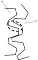
- FIG. 1 is a diagram illustrating an example of a numerical control device and a device connected to the numerical control device. It is a figure showing the meshing state of the 1st gear and the 2nd gear. 3 is a partially enlarged view of a first gear and a second gear shown in FIG. 2.
- FIG. FIG. 2 is a block diagram showing an example of a hardware configuration of a numerical control device. It is a block diagram showing an example of the function of a numerical control device. It is a graph which shows the change of the value of 2nd detection information. It is a graph which shows the change of the value of 2nd calculation information. It is a graph showing an example of difference information. 7 is a flowchart illustrating an example of a procedure for calculating correction information.
- FIG. 3 is a flowchart illustrating an example of the flow of control processing of the transport device.
- FIG. 2 is a block diagram illustrating an example of a function of a numerical control device that generates correction information. It is a graph showing time-series data of the rotational speed of the second gear. It is a figure for explaining the distance between the teeth of a 2nd gear. It is a graph showing the rotational speed of the second gear corrected by the correction section. It is a graph which shows an example of positional information corrected by a correction
- FIG. 1 is a block diagram illustrating an example of functions of a system including a machine learning device and a numerical control device. It is a flowchart which shows an example of the procedure by which a machine learning device generates a learning model. 3 is a flowchart illustrating an example of the flow of control processing of the transport device.
- FIG. 1 is a diagram showing an example of a numerical control device and a device connected to the numerical control device.
- the numerical control device 1 is connected to a first device 2 that is not a control target of the numerical control device 1 and a second device 3 that is a control target of the numerical control device 1 .
- the numerical control device 1 detects the operating state of the first device 2 and operates the second device 3 in synchronization with the operation of the first device 2.
- the second device 3 is, for example, a transport device.
- the transport device is called a transfer.
- the second device 3 may be an industrial robot such as a manipulator.
- the first device 2 is a machine that is not controlled by the numerical control device 1.
- the first device 2 is, for example, a press.
- the first device 2 includes a first shaft 21, a rotating body 22, a handle 23, an upper mold 24, and a lower mold 25.
- the first shaft 21 rotates around the rotation axis.
- a rotating body 22 is attached to the first shaft 21 .
- One end of a handle 23 is pivotally supported on the rotating body 22 at a position a predetermined distance away from the rotating shaft.
- an upper mold 24 is connected to the other end of the handle 23.
- the first device 2 rotates the first shaft 21 to linearly reciprocate the upper mold 24 in the vertical direction.
- a lower mold 25 is installed at a position facing the upper mold 24.
- a workpiece is supplied between the upper mold 24 and the lower mold 25 by the second device 3 .
- press working is performed by the upper mold 24 and the lower mold 25, and the workpiece is formed into a predetermined shape.
- the workpiece is, for example, a steel plate.
- a first gear is attached to the first shaft 21. Further, a second gear that rotates by receiving power from the first gear is attached to a second shaft different from the first shaft 21.
- the first gear and the second gear may directly mesh with each other. Further, the first gear and the second gear may be indirectly engaged with each other via another gear. In other words, the second gear may receive power directly transmitted from the first gear. Further, the second gear may receive power indirectly transmitted from the first gear via one or more gears.
- a sensor that detects the rotational position of the second gear is attached to the second shaft. The rotational position of the second gear is the rotational angle of the second gear.
- FIG. 2 is a diagram showing a state in which the first gear and second gear of the first device 2 are engaged with each other.
- the second gear 27 is arranged, for example, at a position where it directly meshes with the first gear 26. Therefore, when the first gear 26 rotates, the power of the first gear 26 is transmitted to the second gear 27, and the second gear 27 rotates.
- the sensor 28 is installed on the second shaft to which the second gear 27 is attached. Sensor 28 detects the rotational position of second gear 27. Since the first gear 26 and the second gear 27 are in mesh with each other, the rotational position of the first gear 26 can be determined based on the rotational position of the second gear 27. That is, the operating state of the first device 2 can be detected based on the rotational position of the second gear 27.
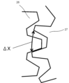
- FIG. 3 is a partially enlarged view of the first gear 26 and second gear 27 shown in FIG. 2. As shown in FIG. 3, a meshing error occurs between the first gear 26 and the second gear 27. In other words, a gap is provided between the tooth surface of the first gear 26 and the tooth surface of the second gear 27. This gap allows the first gear 26 and the second gear 27 to rotate.
- first gear 26 When the first gear 26 is driven with the first gear 26 and the second gear 27 in mesh with each other, there is a gap between the first gear 26 and the second gear 27. Vibration may occur in the gear 27. For example, vibration may occur in the second gear 27 when one tooth of the first gear 26 and one tooth of the second gear 27 begin to come into contact.
- the vibration occurs, for example, in the rotational direction of the second gear 27.
- the rotational speed of the second gear 27 becomes unstable.
- the accurate rotational position of the first gear 26 cannot be determined based on the rotational position of the second gear 27. Therefore, in this embodiment, position information indicating the position of the second gear 27 is corrected using correction information to be described later.
- FIG. 4 is a block diagram showing an example of the hardware configuration of the numerical control device 1.
- the numerical control device 1 includes a hardware processor 11, a bus 12, a ROM (Read Only Memory) 13, a RAM (Random Access Memory) 14, a nonvolatile memory 15, a first interface 16, and a second and an interface 17.
- the hardware processor 11 is a processor that controls the entire numerical control device 1 according to a system program.
- the hardware processor 11 reads out a system program stored in the ROM 13 via the bus 12, and performs various processes based on the system program.
- the hardware processor 11 controls the second device 3 based on an operating program, for example.
- the hardware processor 11 is, for example, a CPU (Central Processing Unit) or an electronic circuit.
- the hardware processor 11 performs, for example, analysis of the operating program and output of control commands to the second device 3 every control cycle. For example, the hardware processor 11 outputs a control command to a servo motor included in the second device 3.
- the bus 12 is a communication path that interconnects each piece of hardware within the numerical control device 1. Each piece of hardware within the numerical control device 1 exchanges data via a bus 12.
- the ROM 13 is a storage device that stores system programs and the like for controlling the entire numerical control device 1.
- ROM 13 is a computer-readable storage medium.
- the RAM 14 is a storage device that temporarily stores various data.
- the RAM 14 functions as a work area for the hardware processor 11 to process various data.
- the nonvolatile memory 15 is a storage device that retains data even when the numerical control device 1 is powered off and power is not supplied to the numerical control device 1.
- the nonvolatile memory 15 stores, for example, operating programs and various parameters.
- Non-volatile memory 15 is a computer readable storage medium.
- the nonvolatile memory 15 includes, for example, battery-backed memory or an SSD (Solid State Drive).
- the first interface 16 is a communication path that connects the bus 12 and the sensor 28.
- the sensor 28 is a sensor 28 that detects the rotational position of the second gear 27 provided in the first device 2.
- the first interface 16 sends information from the sensor 28 to the hardware processor 11, for example.
- the second interface 17 is a communication path that connects the bus 12 and the second device 3.
- the second interface 17 sends control commands from the hardware processor 11 to the second device 3 .
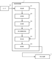
- FIG. 5 is a block diagram showing an example of the functions of the numerical control device 1.
- the numerical control device 1 includes a detection section 101, a correction information storage section 102, a correction section 103, and a control section 104.
- the detection unit 101, the correction unit 103, and the control unit 104 are, for example, calculated by the hardware processor 11 using a system program stored in the ROM 13 and an operation program and various data stored in the nonvolatile memory 15. This is achieved by processing.
- the correction information storage unit 102 is realized, for example, by storing correction information input from an external device in the nonvolatile memory 15.
- the detection unit 101 detects the rotational position of the second gear 27 that rotates by receiving power from the first gear 26. That is, the detection unit 101 acquires position information indicating the rotational position of the second gear 27 based on information from the sensor 28 installed in the first device 2 .
- the position information indicating the rotational position of the second gear 27 is time series data.
- the detection unit 101 acquires, for example, position information indicating the rotational position of the second gear 27 every control period of the hardware processor 11.
- Position information indicating the rotational position of the second gear 27 may be sequentially stored in the RAM 14.
- Position information indicating the rotational position of the second gear 27 may be sequentially stored in the nonvolatile memory 15.
- the correction information storage unit 102 stores correction information.
- the correction information is information for correcting the position information indicating the rotational position of the second gear 27 acquired by the detection unit 101.
- the correction information is information for correcting an error included in the position information indicating the rotational position of the second gear 27 acquired by the detection unit 101.
- the error included in the position information indicating the rotational position of the second gear 27 is the rotational position of the second gear 27 assuming that no vibration occurs in the second gear 27, and the error contained in the position information indicating the rotational position of the second gear 27. This is the difference from the detected rotational position of the second gear 27.
- the position information acquired by the detection unit 101 is information regarding the rotational position affected by vibration caused by the gap provided between the first gear 26 and the second gear 27.
- the correction information is calculated before the numerical control device 1 executes control of the second device 3.
- the correction information is calculated using another machine, for example, before the first gear 26 and the second gear 27 are attached to the first device 2 that is not to be controlled, such as a press.
- the correction information includes second calculation information indicating the rotational position of the second gear 27 calculated based on the first detection information indicating the rotational position of the first gear 26, and second calculation information indicating the rotational position of the second gear 27. includes difference information indicating a difference from the second detection information indicating.
- the first detection information is, for example, information detected when the second gear 27 is rotating in response to power from the first gear 26 in another machine used to calculate the difference information. This is information indicating the rotational position of gear 26 of No. 1.
- the second detection information is, for example, information indicating the rotational position of the second gear 27 detected when the second gear 27 is rotating in response to power from the first gear 26 in another machine. It is. That is, the other machines are each provided with a sensor for detecting the first detection information and a sensor for detecting the second detection information.
- the second calculation information is information indicating the rotational position of the second gear 27 calculated based on the first detection information.
- the second calculation information is calculated based on the first detection information and information such as the number of teeth of each of the first gear 26 and the second gear 27.
- the second calculation information is information indicating the ideal rotational position of the second gear 27 when the second gear 27 rotates in accordance with the rotation of the first gear 26. In other words, it is information regarding a rotational position that is not affected by vibrations caused by the gap provided between the first gear 26 and the second gear 27.
- the difference information is information indicating the difference between the second calculation information and the second detection information. That is, the difference information is information indicating the difference between the information indicating the ideal rotational position of the second gear 27 and the information indicating the rotational position of the second gear 27 actually detected by the sensor. Note that when the shape of the first gear 26 and the shape of the second gear 27 are the same, the difference information may be information indicating the difference between the first detection information and the second detection information. .
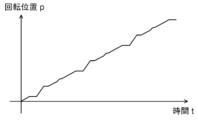
- FIG. 6 is a graph showing changes in the value of the second detection information.
- the vertical axis represents the rotational position of the second gear 27, and the horizontal axis represents time. While the first gear 26 is rotating at a constant speed, the value indicated by the second detection information increases approximately in proportion to time. That is, the graph showing the value of the second detection information is approximately a straight line.
- the meshing period refers to a time interval at which a plurality of teeth included in the first gear 26 and a plurality of teeth included in the second gear 27 each start meshing.
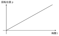
- FIG. 7 is a graph showing changes in the value of the second calculation information. While the first gear 26 is rotating at a constant speed, the value indicated by the second calculation information increases in proportion to time. That is, the graph showing the value of the second calculation information becomes a straight line.
- FIG. 8 is a graph showing an example of difference information.
- the vertical axis represents the difference between the second calculated information and the second detected information
- the horizontal axis represents time.
- the graph showing the change in the value of the difference information is a straight line that generally indicates 0. However, a portion protruding from the straight portion appears at regular intervals.
- the fixed period corresponds to the meshing period when the first gear 26 and the second gear 27 rotate while meshing with each other.
- This difference information is stored in the correction information storage section 102 as correction information.
- the correction information stored in the correction information storage unit 102 is used, for example, as correction information specific to the first gear 26 and the second gear 27 used in calculating the correction information. That is, correction information is calculated for each set of gears consisting of the first gear 26 and the second gear 27. Once the correction information is calculated, the first gear 26 and the second gear 27 are removed from another machine and attached to the first device 2 that is not to be controlled, such as a press machine.
- the correction information may be calculated using the first device 2 that is not to be controlled.
- the correction information may be calculated during the assembly process of the first device 2.
- a sensor for detecting the first detection information and a sensor for detecting the second detection information are respectively attached to the first device 2.
- the sensor for detecting the first detection information is removed from the first device 2 during the operation stage of the first device 2. .
- the correction unit 103 corrects the position information indicating the rotational position of the second gear 27 detected by the detection unit 101 based on the correction information. For example, when the detection unit 101 detects position information similar to the second detection information shown in FIG. Correct information. Specifically, the correction unit 103 adds the value indicated by the difference information to the value indicating the position information of the uneven portion that appears in each meshing cycle. As a result, the position information indicating the rotational position of the second gear 27 is corrected.
- the control unit 104 operates the second device 3 in synchronization with the rotation of the first gear 26 based on the position information corrected by the correction unit 103.
- the control unit 104 controls the second device 3 to synchronize with the operation of the press machine. That is, the control unit 104 controls the second device 3 so that the steel plate transported by the second device 3 is supplied to the press at an appropriate timing.
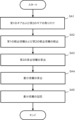
- FIG. 9 is a flowchart illustrating an example of a procedure for calculating correction information.
- the first gear 26 and the second gear 27 are attached to another machine different from the first device 2 in a meshing state (step SA1).
- the first detection information and the second detection information are detected while the first gear 26 is rotated at a predetermined rotational speed (step SA2).
- the detected first detection information and second detection information are stored, for example, in a storage area of a storage device included in another machine.
- step SA3 second calculation information is calculated based on the first detection information.
- the second calculation information is calculated, for example, by a hardware processor included in another machine.
- difference information is calculated based on the second calculation information and the second detection information (step SA4).
- the difference information is calculated, for example, by a hardware processor included in another machine.
- the difference information is stored as correction information in the correction information storage unit 102 (step SA5).
- the calculated difference information is sent from another machine to the numerical control device 1 via a network, for example, and is stored in the correction information storage section 102.
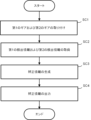
- FIG. 10 is a flowchart showing an example of the flow of control processing of the second device 3 executed by the numerical control device 1.
- the detection unit 101 detects position information indicating the rotational position of the second gear 27, which rotates by receiving power from the first gear 26 (step SB1).
- the correction unit 103 corrects the position information detected by the detection unit 101 based on the correction information (step SB2).
- control unit 104 controls the second device 3 in synchronization with the rotation of the first gear 26 based on the position information corrected by the correction unit 103 (step SB3), and ends the process.
- the numerical control device 1 that operates the device includes a detection unit 101 that detects the rotational position of the second gear 27, and a correction unit that corrects position information indicating the rotational position detected by the detection unit 101 based on correction information. 103 , and a control unit 104 that operates the second device 3 in synchronization with the rotation of the first gear 26 based on the position information corrected by the correction unit 103 .
- the numerical control device 1 can detect the rotational position of the second gear 27 while eliminating the influence of vibrations that occur when the first gear 26 and the second gear 27 rotate.
- the second device 3 can be operated in synchronization with the operation of the first device 2 with high precision.
- the correction information is calculated based on first detection information indicating the rotational position of the first gear 26 detected while the second gear 27 is rotating due to receiving power from the first gear 26.
- the second calculated information indicating the rotational position of the second gear 27 that has been detected, and the second calculated information indicating the rotational position of the second gear 27 detected when the second gear 27 is rotating in response to receiving power from the first gear 26. It includes difference information indicating a difference from the second detection information indicating the rotational position.
- the correction unit 103 corrects the position information indicating the rotational position of the second gear 27 based on one piece of correction information calculated in advance.
- the correction unit 103 may select one piece of correction information from a plurality of pieces of correction information calculated in advance, and correct the position information based on the selected correction information.
- the difference information may include a plurality of pieces of difference information (hereinafter referred to as "speed-corresponding difference information") each calculated when the first gear 26 rotates at a plurality of different speeds. That is, in a machine other than the first device 2, the first gear 26 and the second gear 27 are engaged with each other in advance, and the first gear 26 is rotated at a plurality of different speeds. Then, based on the first detection information detected when the first gear 26 rotates at each speed, the second calculation information calculated from the first detection information, and the second detection information, each A plurality of speed-corresponding difference information is calculated according to the speed.
- speed-corresponding difference information a plurality of pieces of difference information
- the correction unit 103 selects one speed stored in association with the rotational speed closest to the rotational speed at which the first gear 26 is rotating in the first device 2, based on the plurality of speed-corresponding difference information.
- the position information indicating the rotational position of the second gear 27 may be corrected by selecting the corresponding difference information.
- the first detection information and the second detection information are detected in another machine in order to calculate the difference information
- the first detection information and the second detection information are It may be detected simultaneously or individually when the second gear 27 and the second gear 27 are meshing and rotating.
- the other machines include a sensor that detects the rotational position of the first gear 26 and a sensor that detects the rotational position of the second gear 27. and is provided.
- a sensor that detects the rotational position of the first gear 26 is first attached to the first gear 26, and the first detection information is detected separately. Detection information is detected. Thereafter, the sensor is removed from the first gear 26 and attached to the second gear 27, and second detection information is detected.
- the correction information may be information associated with one tooth included in the first gear 26 or the second gear 27. Specifically, the correction information may be stored in association with each tooth of the first gear 26 or the second gear 27. In this case, the position information indicating the rotational position of the second gear 27 is corrected based on the correction information stored in association with each tooth. As a result, the position information indicating the rotational position of the second gear 27 is corrected with high accuracy.
- correction information is one piece of information associated with the first gear 26 or the second gear 27, there is no need to store multiple pieces of correction information in association with each tooth. As a result, the storage area for storing correction information can be reduced.
- the correction information is calculated in advance using a machine other than the first device 2.
- the correction information may be generated by the numerical control device 1.
- FIG. 11 is a block diagram showing an example of the functions of the numerical control device 1 that generates correction information.
- the numerical control device 1 shown in FIG. 11 differs from the numerical control device 1 shown in FIG. 5 in that it includes a determining section 105 and a generating section 106. Therefore, the functions related to the determining unit 105 and the generating unit 106 will be described here, and the description of other functions will be omitted.
- the determining unit 105 and the generating unit 106 are realized, for example, by the hardware processor 11 performing arithmetic processing using the system program stored in the ROM 13 and various data stored in the nonvolatile memory 15.
- the detection unit 101 starts detecting the rotational position of the second gear 27 that rotates by receiving power from the first gear 26.
- Position information indicating the rotational position of the second gear 27 may be sequentially stored in the RAM 14 or the nonvolatile memory 15.
- the determining unit 105 determines a correction section to be corrected by the correcting unit 103 out of the time series data of the position information indicating the rotational position of the second gear 27 detected by the detecting unit 101.
- the determining unit 105 determines the correction section based on the rotational speed of the second gear 27 calculated from position information indicating the rotational position of the second gear 27, for example.
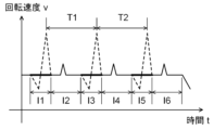
- FIG. 12 is a graph showing time series data of the rotational speed of the second gear 27 calculated by the determining unit 105.
- the meshing period is calculated as follows, for example. First, the average speed of the rotational speed is determined from the time-series data of the rotational speed. Next, the interval between each peak value that deviates significantly from the average speed is determined as the meshing period.
- the peak value that deviates significantly from the average speed is, for example, a peak value that is greater than or equal to a predetermined threshold value. That is, a peak value that is less than or equal to a predetermined threshold value is ignored when calculating the meshing period.
- a predetermined threshold value for example, a value indicating a ratio according to the average speed or a predetermined value is used.
- the time intervals T1 and T2 are the meshing period.
- the meshing period includes a stable period in which the second gear 27 rotates at a stable speed and an unstable period in which the second gear 27 rotates at an unstable speed.
- the unstable section can be, for example, a predetermined period before and after a peak value that deviates significantly from the average speed in the meshing cycle.
- the predetermined period can be, for example, a period of a predetermined ratio to the meshing cycle.
- the meshing period may be calculated from waveform data indicating the speed obtained by frequency analysis of the rate of change of position data indicating the rotational position of the second gear 27.
- the determining unit 105 determines the unstable interval as the correction interval. That is, the position information included in the correction section or the speed information included in the correction section and calculated from the position information is subject to correction by the correction unit 103.
- section I1, section I3, and section I5 are correction sections.
- the section I2, the section I4, and the section I6 are sections other than the correction section.
- the generation unit 106 generates correction information based on position information included in an interval other than the correction interval determined by the determination unit 105.
- the position information is a concept that also includes speed information calculated from the position information. That is, the generation unit 106 may generate correction information based on speed information calculated from position information. For example, the generation unit 106 generates the correction information using speed information near the boundary position between the correction section and the section other than the correction section.
- the generation unit 106 can calculate the correction information using, for example, the following equations 1 and 2.
- Vs is the rotational speed of the second gear 27
- ⁇ X is the distance between the teeth of the second gear 27 (see FIG. 13)
- T1 is the meshing period.
- p position information indicating the corrected rotational position of the second gear 27
- P1 is position information near the boundary position between the correction section and a section other than the correction section
- ⁇ t is position information indicating the detected position at the boundary position. This is the elapsed time from the time when the The correction information generated by the generation unit 106 may be stored in the correction information storage unit 102.
- the correction unit 103 corrects the speed information included in the correction interval based on the correction information generated by the generation unit 106. Further, the correction unit 103 calculates position information indicating the rotational position of the second gear 27 based on the corrected speed information.
- FIG. 14 is a graph showing the rotational speed of the second gear 27 corrected by the correction unit 103.
- the graph of FIG. 14 shows that the rotational speed of the correction section is corrected based on the rotational speed of the boundary position between the correction section and the section other than the correction section.
- the correction unit 103 calculates position information indicating the rotational position of the second gear 27 based on the corrected speed information.
- FIG. 15 is a graph showing an example of position information corrected by the correction unit 103.
- the graph in FIG. 15 shows that the position information of sections I1, I3, and I5 has been corrected using the correction information.
- the generation unit 106 may generate the correction information based on the rate of change of the value indicated by the position information in an area other than the correction area.
- the graph showing the rotational position of the second gear 27 becomes like the graph shown in FIG. 15.
- the correction unit 103 corrects the position information based on the rotation command to rotate the first gear 26. It may be corrected.
- the machine learning device learns the correlation between the rotational position of the first gear 26 and the rotational position of the second gear 27, and the numerical control device 1 adjusts the rotational position of the second gear based on the correction information generated by the machine learning device.
- the position information indicating the position of No. 27 may be corrected.
- the correction information is a learning model.
- FIG. 16 is a block diagram showing an example of the functions of a system including the machine learning device and the numerical control device 1.
- the machine learning device 4 includes an acquisition section 41 and a learning model generation section 42.
- the acquisition unit 41 and the learning model generation unit 42 are realized, for example, by a hardware processor included in the machine learning device 4 executing a system program or the like.
- the acquisition unit 41 acquires first detection information indicating the rotational position of the first gear 26 detected when the first gear 26 and the second gear 27 rotate while meshing with each other; Second detection information indicating the rotational position of the second gear 27 detected when the second gear 27 meshes with the second gear 27 and rotates is acquired.
- the first detection information and the second detection information are time series data.
- the acquisition unit 41 acquires, for example, the first detection information and the second detection information every control cycle of the hardware processor included in the machine learning device 4.
- the first detection information and the second detection information are obtained, for example, when the first gear 26 and the second gear 27 are attached to a machine other than the first device 2 and rotated in mesh with each other. Ru.
- the learning model generation unit 42 executes supervised learning using the second detection information acquired by the acquisition unit 41 as input data and the first detection information as label data. That is, the learning model generation unit 42 executes supervised learning using the first detection information and the second detection information as a data set.
- the data set associates second detection information acquired in a plurality of consecutive control cycles with first detection information acquired in one control cycle among the plurality of consecutive control cycles.
- the data set may be That is, the data set may be data in which time series data and instantaneous values are associated with each other.
- the learning model generation unit 42 generates correction information indicating the correlation between the rotational position of the first gear 26 and the rotational position of the second gear 27.
- the numerical control device 1 includes a detection section 101, a correction section 103, and a control section 104.
- the detection unit 101 detects position information indicating the rotational position of the second gear 27 that meshes with the first gear 26 in the first device 2.
- the correction unit 103 corrects the position information indicating the rotational position of the second gear 27 detected by the detection unit 101 based on the correction information.
- the correction unit 103 inputs into the learning model the correction information generated by the machine learning device 4, that is, the position information indicating the rotational position of the second gear 27 that meshes with the first gear 26, and adjusts the position of the first gear 26.
- First calculation information indicating the rotational position is calculated.
- the first calculation information calculated by the correction unit 103 is position information that is not affected by vibration. In other words, the first calculation information can be said to be position information in which the position information indicating the rotational position of the second gear 27 is corrected by the correction information.
- the control unit 104 operates the second device 3 in synchronization with the rotation of the first gear 26 based on the position information corrected by the correction unit 103, in other words, based on the first calculation information.
- FIG. 17 is a flowchart illustrating an example of a procedure in which the machine learning device 4 generates correction information, that is, a learning model.
- the first gear 26 and the second gear 27 are attached to a machine other than the first device 2 that is not to be controlled, with the first gear 26 and the second gear 27 meshing with each other (step SC1).
- the acquisition unit 41 acquires the first detection information and the second detection information (step SC2).
- the first detection information is obtained from a sensor that detects the rotational position of the first gear 26.
- the second detection information is obtained from a sensor that detects the rotational position of the second gear 27.
- the acquired first detection information and second detection information are stored, for example, in a storage area of a storage device included in another machine.
- the learning model generation unit 42 generates correction information indicating the correlation between the rotational position of the first gear 26 and the rotational position of the second gear 27. (Step SC3).
- step SC4 the generated correction information is output to the numerical control device 1 (step SC4), and the process ends.
- FIG. 18 is a flowchart showing an example of the flow of control processing of the second device 3 executed by the numerical control device 1.
- the detection unit 101 detects position information indicating the rotational position of the second gear 27 that meshes with the first gear 26 (step SD1).
- the correction unit 103 inputs position information indicating the rotational position of the second gear 27 into the correction information and calculates first calculation information indicating the rotational position of the first gear 26 (step SD2).
- control unit 104 controls the second device 3 in synchronization with the rotation of the first gear 26 based on the position information calculated by the correction unit 103 (step SD3), and ends the process.
- the correction information may be a learning model generated by the machine learning device 4.
- the machine learning device 4 also receives first detection information indicating the rotational position of the first gear 26 detected when the second gear 27 is rotating in response to power received from the first gear 26; an acquisition unit 41 that acquires second detection information indicating a rotational position of the second gear 27 that is detected while the second gear 27 is rotating in response to receiving power from the first gear 26; Supervised learning is performed using the second detection information acquired by the unit 41 as input data and the first detection information as label data to determine the rotational position of the first gear 26 and the rotational position of the second gear 27.
- a learning model generation unit 42 that generates a learning model showing the correlation between Alternatively, the first calculation information indicating the rotational position of the first gear 26 may be calculated. In this case, the number of steps for generating correction information can be reduced.
- the acquisition unit 41 of the machine learning device 4 acquires the first detection information and the second detection information when the first gear 26 and the second gear 27 rotate at a plurality of rotational speeds. You may obtain each. That is, when the second gear 27 rotates at a plurality of speeds, the acquisition unit 41 combines rotational speed information indicating each rotational speed, the first detection information, and the second detection information into one data set. You may also obtain data for
- the learning model generation unit 42 executes supervised learning using, for example, the rotational speed information of the second gear 27 and the second detection information as input data and the first detection information as label data.
- the learning model generation unit 42 generates correction information indicating the correlation between the rotational speed of the second gear 27 and the rotational position of the second gear 27 and the rotational position of the first gear 26.
- the correction unit 103 of the numerical control device 1 adds position information indicating the rotational position of the second gear 27 to the correction information generated by the machine learning device 4, and the position information indicating the rotational position of the second gear 27 when the position information is detected.
- First calculation information indicating the rotational position of the first gear 26 is calculated by inputting rotational speed information indicating the rotational speed of the first gear 26 .
- the control unit 104 can operate the second device 3 in synchronization with the rotation of the first gear 26.
Landscapes
- Engineering & Computer Science (AREA)
- Mechanical Engineering (AREA)
- Human Computer Interaction (AREA)
- Manufacturing & Machinery (AREA)
- Physics & Mathematics (AREA)
- General Physics & Mathematics (AREA)
- Automation & Control Theory (AREA)
- Numerical Control (AREA)
Abstract
非制御対象の第1の装置が有する第1のギアから動力を受けて回転する第2のギアの回転位置に基づいて、第1のギアの回転に同期させて第2の装置を動作させる数値制御装置が、第2のギアの回転位置を検出する検出部と、検出部によって検出された回転位置を示す位置情報を補正情報に基づいて補正する補正部と、補正部によって補正された位置情報に基づいて第1のギアの回転に同期させて第2の装置を動作させる制御部と、を備える。
Description
本開示は、数値制御装置に関する。
従来、互いに噛み合う2つのギアのうちの一方のギアの回転角を、他方の検出用ギアの回転角に基づいて検出する技術が知られている(例えば、特許文献1)。この技術を利用すれば、一方のギアの回転に合わせて別の装置を動作させたい場合に検出用ギアの回転角に基づいて別の装置を動作させることができる。
しかし、一方のギアから検出用ギアへ動力が伝達される際に振動が生じた場合は、一方のギアの回転角の検出精度が低下してしまう。この場合、一方のギアと別の装置とを同期させて制御する際の同期精度が低下するおそれがある。
したがって、ギアの噛み合い時に生じる振動の影響を排除してギアの回転角を高精度に検出できる技術が求められている。
非制御対象の第1の装置が有する第1のギアから動力を受けて回転する第2のギアの回転位置に基づいて、第1のギアの回転に同期させて第2の装置を動作させる数値制御装置が、第2のギアの回転位置を検出する検出部と、検出部によって検出された回転位置を示す位置情報を補正情報に基づいて補正する補正部と、補正部によって補正された位置情報に基づいて第1のギアの回転に同期させて第2の装置を動作させる制御部と、を備える。
本開示の一態様により、ギアの噛み合い時に生じる振動の影響を排除してギアの回転角を高精度に検出できる。
以下、本開示の実施形態に係る数値制御装置について図面を用いて説明する。なお、以下の実施形態で説明する特徴のすべての組み合わせが課題解決に必ずしも必要であるとは限らない。また、必要以上の詳細な説明を省略する場合がある。また、以下の実施形態の説明、および図面は、当業者が本開示を十分に理解するために提供されるものであり、請求の範囲を限定することを意図していない。
図1は、数値制御装置および数値制御装置に接続される装置の一例を示す図である。数値制御装置1は、数値制御装置1の制御対象ではない非制御対象の第1の装置2、および数値制御装置1の制御対象の第2の装置3に接続される。数値制御装置1は、第1の装置2の動作状態を検出して、第1の装置2の動作に同期させて第2の装置3を動作させる。第2の装置3は、例えば、搬送装置である。搬送装置は、トランスファと称される。第2の装置3は、マニピュレータなどの産業用ロボットであってもよい。
第1の装置2は、数値制御装置1によって制御されない機械である。第1の装置2は、例えば、プレス機である。第1の装置2は、第1のシャフト21と、回転体22と、柄23と、上金型24と、下金型25とを備える。
第1のシャフト21は、回転軸を中心に回転する。第1のシャフト21には、回転体22が取り付けられている。回転体22には、回転軸から所定距離だけ離れた位置に柄23の一端が軸支される。また、柄23の他端には上金型24が連結される。第1の装置2は、第1のシャフト21を回転させることにより、上金型24を上下方向に往復直線運動させる。
上金型24に対向する位置には、下金型25が設置される。上金型24と下金型25との間には、第2の装置3によって被加工物が供給される。上金型24と下金型25との間に被加工物が供給されると、上金型24と下金型25によりプレス加工が行われ、被加工物が所定の形状に形成される。被加工物は、例えば、鋼板である。
第1のシャフト21には第1のギアが取り付けられる。また、第1のシャフト21とは異なる第2のシャフトには第1のギアから動力を受けて回転する第2のギアが取り付けられる。第1のギアと第2のギアとは、直接噛み合っていてもよい。また、第1のギアと第2のギアとは、他のギアを介して間接的に噛み合っていてもよい。言い換えれば、第2のギアは、第1のギアから直接動力の伝達を受けてもよい。また、第2のギアは、1または複数のギアを介して第1のギアから間接的に動力の伝達を受けてもよい。第2のシャフトには、第2のギアの回転位置を検出するセンサが取り付けられる。第2のギアの回転位置とは、第2のギアの回転角である。
図2は、第1の装置2が有する第1のギアと第2のギアとの噛み合い状態を示す図である。第2のギア27は、例えば、第1のギア26と直接噛み合う位置に配置される。したがって、第1のギア26が回転すると第1のギア26の動力が第2のギア27に伝達し、第2のギア27が回転する。
センサ28は、第2のギア27が取り付けられる第2のシャフトに設置される。センサ28は第2のギア27の回転位置を検出する。第1のギア26と第2のギア27とは噛み合っているため、第2のギア27の回転位置に基づいて、第1のギア26の回転位置を求めることができる。つまり、第2のギア27の回転位置に基づいて第1の装置2の動作状態を検出することができる。
図3は、図2に示す第1のギア26および第2のギア27の一部拡大図である。図3に示すように、第1のギア26と第2のギア27との間には噛み合い誤差が生じる。言い換えると、第1のギア26の歯面と第2のギア27の歯面との間には、隙間が設けられる。この隙間があることによって、第1のギア26と第2のギア27とが回転することができる。
第1のギア26と第2のギア27とが噛み合った状態で第1のギア26を駆動させると、第1のギア26と第2のギア27との間には隙間があるため、第2のギア27に振動が生じる場合がある。例えば、第1のギア26の1つの歯と第2のギア27の1つの歯との接触が開始するときに第2のギア27に振動が生じる場合がある。
振動は、例えば、第2のギア27の回転方向に生じる。第2のギア27に振動が生じると第2のギア27の回転速度が不安定になる。この場合、第2のギア27の回転位置に基づいて第1のギア26の正確な回転位置を求めることができない。そのため、本実施形態では、後述する補正情報を用いて第2のギア27の位置を示す位置情報が補正される。
図4は、数値制御装置1のハードウェア構成の一例を示すブロック図である。数値制御装置1は、ハードウェアプロセッサ11と、バス12と、ROM(Read Only Memory)13と、RAM(Random Access Memory)14と、不揮発性メモリ15と、第1のインタフェース16と、第2のインタフェース17とを備える。
ハードウェアプロセッサ11は、システムプログラムに従って数値制御装置1全体を制御するプロセッサである。ハードウェアプロセッサ11は、バス12を介してROM13に格納されたシステムプログラムなどを読み出し、システムプログラムに基づいて各種処理を行う。ハードウェアプロセッサ11は、例えば、動作プログラムに基づいて、第2の装置3を制御する。ハードウェアプロセッサ11は、例えば、CPU(Central Processing Unit)、または電子回路である。
ハードウェアプロセッサ11は、制御周期ごとに、例えば、動作プログラムの解析、ならびに、第2の装置3に対する制御指令の出力を行う。ハードウェアプロセッサ11は、例えば、第2の装置3が備えるサーボモータに向けて制御指令を出力する。
バス12は、数値制御装置1内の各ハードウェアを互いに接続する通信路である。数値制御装置1内の各ハードウェアはバス12を介してデータをやり取りする。
ROM13は、数値制御装置1全体を制御するためのシステムプログラムなどを記憶する記憶装置である。ROM13は、コンピュータ読み取り可能な記憶媒体である。
RAM14は、各種データを一時的に格納する記憶装置である。RAM14は、ハードウェアプロセッサ11が各種データを処理するための作業領域として機能する。
不揮発性メモリ15は、数値制御装置1の電源が切られ、数値制御装置1に電力が供給されていない状態でもデータを保持する記憶装置である。不揮発性メモリ15は、例えば、動作プログラム、および各種パラメータを記憶する。不揮発性メモリ15は、コンピュータ読み取り可能な記憶媒体である。不揮発性メモリ15は、例えば、バッテリでバックアップされたメモリ、または、SSD(Solid State Drive)で構成される。
第1のインタフェース16は、バス12とセンサ28とを接続する通信路である。センサ28とは、第1の装置2に設けられた第2のギア27の回転位置を検出するセンサ28である。第1のインタフェース16は、センサ28からの情報を、例えば、ハードウェアプロセッサ11に送る。
第2のインタフェース17は、バス12と第2の装置3とを接続する通信路である。第2のインタフェース17は、ハードウェアプロセッサ11からの制御指令を第2の装置3に送る。
図5は、数値制御装置1の機能の一例を示すブロック図である。数値制御装置1は、検出部101と、補正情報記憶部102と、補正部103と、制御部104とを備える。
検出部101、補正部103、および制御部104は、例えば、ハードウェアプロセッサ11が、ROM13に記憶されたシステムプログラム、ならびに、不揮発性メモリ15に記憶されている動作プログラムおよび各種データを用いて演算処理することにより実現される。補正情報記憶部102は、例えば、外部機器から入力された補正情報が不揮発性メモリ15に記憶されることにより実現される。
検出部101は、第1のギア26から動力を受けて回転する第2のギア27の回転位置を検出する。つまり、検出部101は、第1の装置2に設置されたセンサ28からの情報に基づいて第2のギア27の回転位置を示す位置情報を取得する。第2のギア27の回転位置を示す位置情報は、時系列データである。検出部101は、例えば、ハードウェアプロセッサ11の制御周期毎に第2のギア27の回転位置を示す位置情報を取得する。第2のギア27の回転位置を示す位置情報は、RAM14に順次記憶されてよい。第2のギア27の回転位置を示す位置情報は、不揮発性メモリ15に順次記憶されてもよい。
補正情報記憶部102は、補正情報を記憶する。補正情報は、検出部101によって取得された第2のギア27の回転位置を示す位置情報を補正するための情報である。言い換えれば、補正情報は、検出部101によって取得された第2のギア27の回転位置を示す位置情報に含まれる誤差を補正するための情報である。
第2のギア27の回転位置を示す位置情報に含まれる誤差とは、第2のギア27に振動が発生していないと仮定した場合の第2のギア27の回転位置と、検出部101によって検出された第2のギア27の回転位置との差である。検出部101によって取得される位置情報は、第1のギア26と第2のギア27との間に設けられた隙間に起因する振動の影響を受けた回転位置に関する情報である。
補正情報は、数値制御装置1が第2の装置3の制御を実行する前に算出される。補正情報は、例えば、第1のギア26と第2のギア27とがプレス機などの非制御対象の第1の装置2に取り付けられる前に他の機械を利用して算出される。
補正情報は、第1のギア26の回転位置を示す第1の検出情報に基づいて算出された第2のギア27の回転位置を示す第2の算出情報と、第2のギア27の回転位置を示す第2の検出情報との差分を示す差分情報を含む。
第1の検出情報は、例えば、差分情報を算出するために利用される他の機械において、第1のギア26から動力を受けて第2のギア27が回転しているときに検出された第1のギア26の回転位置を示す情報である。第2の検出情報は、例えば、他の機械において、第1のギア26から動力を受けて第2のギア27が回転しているときに検出された第2のギア27の回転位置を示す情報である。すなわち、他の機械には、第1の検出情報を検出するためのセンサ、および第2の検出情報を検出するためのセンサがそれぞれ設けられる。
第2の算出情報は、第1の検出情報に基づいて算出された第2のギア27の回転位置を示す情報である。第2の算出情報は、第1の検出情報、ならびに、第1のギア26および第2のギア27のそれぞれの歯数など情報に基づいて算出される。第2の算出情報は、第1のギア26の回転に従って第2のギア27が回転するときの第2のギア27の理想的な回転位置を示す情報である。つまり、第1のギア26と第2のギア27との間に設けられた隙間に起因する振動の影響を受けていない回転位置に関する情報である。
差分情報は、第2の算出情報と第2の検出情報との差分を示す情報である。つまり、差分情報は、第2のギア27の理想的な回転位置を示す情報と、実際にセンサによって検出された第2のギア27の回転位置を示す情報との差分を示す情報である。なお、第1のギア26の形状と第2のギア27の形状とが同じである場合、差分情報は、第1の検出情報と第2の検出情報との差分を示す情報であってもよい。
図6は、第2の検出情報の値の推移を示すグラフである。このグラフにおいて、縦軸は第2のギア27の回転位置、横軸は時間を示している。第1のギア26が一定の速度で回転している間、第2の検出情報が示す値は、概ね時間に比例して増加する。すなわち、第2の検出情報の値を示すグラフは、概ね直線となる。
ただし、およそ一定の周期ごとに、グラフには凹凸が現れる。この凹凸は、第1のギア26の歯と第2のギア27の歯との噛み合いが開始するときの衝撃により第2のギア27に振動が生じたことを示している。なお、この凹凸が現れる周期は、第1のギア26と第2のギア27との噛み合い周期に一致する。噛み合い周期とは、第1のギア26に含まれる複数の歯と第2のギア27に含まれる複数の歯とがそれぞれ噛み合いを開始する時間間隔をいう。
図7は、第2の算出情報の値の推移を示すグラフである。第1のギア26が一定の速度で回転している間、第2の算出情報が示す値は、時間に比例して増加する。すなわち、第2の算出情報の値を示すグラフは、直線となる。
図8は、差分情報の一例を示すグラフである。このグラフにおいて、縦軸は第2の算出情報と第2の検出情報との差分、横軸は時間である。差分情報の値の推移を示すグラフは、概ね0を示す直線となる。ただし、一定の周期毎に直線部分から突出する部分が現れる。一定の周期は、第1のギア26と第2のギア27とが噛み合って回転するときの噛み合い周期に一致する。この差分情報が補正情報記憶部102に補正情報として記憶される。
補正情報記憶部102に記憶された補正情報は、例えば、補正情報の算出に用いられた第1のギア26および第2のギア27に固有の補正情報として利用される。すなわち、第1のギア26と第2のギア27とからなる1組のギアごとに補正情報が算出される。補正情報が算出されると、第1のギア26および第2のギア27は他の機械から取り外され、プレス機などの非制御対象の第1の装置2に取り付けられる。
なお、補正情報は、非制御対象の第1の装置2を用いて算出されてもよい。例えば、第1の装置2の組み立て工程において補正情報が算出されてもよい。この場合、第1の装置2には、第1の検出情報を検出するためのセンサ、および第2の検出情報を検出するためのセンサがそれぞれ取り付けられる。そして、第1の装置2を用いて補正情報が算出された場合、第1の装置2の運用段階においては、第1の検出情報を検出するためのセンサは、第1の装置2から取り外される。ここで、図5の説明に戻る。
補正部103は、検出部101によって検出された第2のギア27の回転位置を示す位置情報を補正情報に基づいて補正する。例えば、検出部101が図6に示す第2の検出情報と同様の位置情報を検出した場合、補正部103は、図8に示す補正情報に基づいて第2のギア27の回転位置を示す位置情報を補正する。具体的には、補正部103は、噛み合い周期毎に現れる凹凸部分の位置情報を示す値に差分情報が示す値を加算する。これにより、第2のギア27の回転位置を示す位置情報が補正される。
制御部104は、補正部103によって補正された位置情報に基づいて、第1のギア26の回転に同期させて第2の装置3を動作させる。上述したように、例えば、非制御対象の第1の装置2がプレス機である場合、制御部104は、プレス機の動作に同期させるように第2の装置3を制御する。すなわち、制御部104は、第2の装置3によって搬送される鋼板が適切なタイミングでプレス機に供給されるように、第2の装置3を制御する。
図9は、補正情報を算出する手順の一例を示すフローチャートである。まず、第1の装置2とは異なる他の機械に第1のギア26と第2のギア27とが噛み合う状態で取り付けられる(ステップSA1)。
次に、第1のギア26をあらかじめ定められた回転速度で回転させた状態で、第1の検出情報と第2の検出情報とが検出される(ステップSA2)。検出された第1の検出情報および第2の検出情報は、例えば、他の機械が有する記憶装置の記憶領域に記憶される。
次に、第1の検出情報に基づいて第2の算出情報が算出される(ステップSA3)。第2の算出情報は、例えば、他の機械が有するハードウェアプロセッサによって算出される。
次に、第2の算出情報と第2の検出情報に基づいて、差分情報が算出される(ステップSA4)。差分情報は、例えば、他の機械が有するハードウェアプロセッサによって算出される。
最後に、差分情報が補正情報として補正情報記憶部102に記憶される(ステップSA5)。算出された差分情報は、例えば、ネットワークを介して他の機械から数値制御装置1に送られ、補正情報記憶部102に記憶される。
図10は、数値制御装置1が実行する第2の装置3の制御処理の流れの一例を示すフローチャートである。
まず、検出部101が、第1のギア26から動力を受けて回転する第2のギア27の回転位置を示す位置情報を検出する(ステップSB1)。
次に、補正部103が、検出部101によって検出された位置情報を補正情報に基づいて補正する(ステップSB2)。
最後に、制御部104が、補正部103によって補正された位置情報に基づいて、第1のギア26の回転に同期させて第2の装置3を制御し(ステップSB3)、処理を終了する。
以上説明したように、非制御対象の第1の装置が有する第1のギアから動力を受けて回転する第2のギアの回転位置に基づいて、第1のギアの回転に同期させて第2の装置を動作させる数値制御装置1が、第2のギア27の回転位置を検出する検出部101と、検出部101によって検出された回転位置を示す位置情報を補正情報に基づいて補正する補正部103と、補正部103によって補正された位置情報に基づいて第1のギア26の回転に同期させて第2の装置3を動作させる制御部104と、を備える。
したがって、数値制御装置1は、第1のギア26と第2のギア27との回転時に生じる振動の影響を排除して第2のギア27の回転位置を検出することができる。その結果、第1の装置2の動作に精度よく同期させて第2の装置3を動作させることができる。
また、補正情報は、第1のギア26から動力を受けて第2のギア27が回転しているときに検出された第1のギア26の回転位置を示す第1の検出情報に基づいて算出された第2のギア27の回転位置を示す第2の算出情報と、第1のギア26から動力を受けて第2のギア27が回転しているときに検出された第2のギア27の回転位置を示す第2の検出情報との差分を示す差分情報を含む。
上述した実施形態では、補正部103は、あらかじめ算出された1つの補正情報に基づいて第2のギア27の回転位置を示す位置情報を補正する。しかし、補正部103は、あらかじめ算出された複数の補正情報のうちから1つの補正情報を選択し、選択した当該補正情報に基づいて位置情報を補正してもよい。
例えば、差分情報は、第1のギア26が互いに異なる複数の速度で回転したときにそれぞれ算出された複数の差分情報(以下「速度対応差分情報」という。)を含んでいてよい。すなわち、第1の装置2以外の他の機械においてあらかじめ第1のギア26と第2のギア27とを噛み合った状態で第1のギア26を複数種類の速度で回転させる。そして、第1のギア26が各速度で回転したときに検出された第1の検出情報および第1の検出情報から算出された第2の算出情報、ならびに第2の検出情報に基づいて、各速度に応じた複数の速度対応差分情報を算出する。
補正部103は、これら複数の速度対応差分情報から、第1の装置2において第1のギア26が回転しているときの回転速度に最も近い回転速度に対応付けて記憶されている一の速度対応差分情報を選択して第2のギア27の回転位置を示す位置情報を補正してよい。
また、差分情報を算出するために他の機械において第1の検出情報と第2の検出情報とが検出される場合、第1の検出情報と第2の検出情報とは、第1のギア26と第2のギア27とが噛み合って回転しているときに同時に、または個別に検出されてよい。
第1の検出情報と第2の検出情報とが同時に検出される場合、他の機械には、第1のギア26の回転位置を検出するセンサと第2のギア27の回転位置を検出するセンサとが設けられる。一方、第1の検出情報と第2の検出情報とが別個に検出される場合、例えば、先に第1のギア26の回転位置を検出するセンサが第1のギア26に取り付けられ、第1の検出情報が検出される。その後、センサは、第1のギア26から取り外されて第2のギア27に取り付けられ、第2の検出情報が検出される。
また、補正情報は、第1のギア26または第2のギア27に含まれる1つの歯に対応付けられた情報であってよい。具体的には、第1のギア26または第2のギア27の各歯に対応付けて補正情報を記憶してもよい。この場合、各歯に対応付けて記憶された補正情報に基づいて第2のギア27の回転位置を示す位置情報が補正される。その結果、第2のギア27の回転位置を示す位置情報が精度よく補正される。
補正情報が、第1のギア26または第2のギア27に対応付けられた1つの情報である場合、各歯に対応付けて複数の補正情報を記憶させておく必要がない。その結果、補正情報を記憶するための記憶領域を削減することができる。
上述した実施形態では、補正情報は、あらかじめ第1の装置2以外の他の機械を用いて算出される。しかし、補正情報は、数値制御装置1が生成してもよい。
図11は、補正情報を生成する数値制御装置1の機能の一例を示すブロック図である。図11に示す数値制御装置1は、決定部105、および生成部106を備えている点で、図5に示す数値制御装置1とは異なる。したがって、ここでは、決定部105、および生成部106に関連する機能について説明し、これら以外の機能については説明を省略する。
決定部105および生成部106は、例えば、ハードウェアプロセッサ11が、ROM13に記憶されたシステムプログラム、ならびに、不揮発性メモリ15に記憶されている各種データを用いて演算処理することにより実現される。
プレス機などの非制御対象の第1の装置2が動作を開始すると、検出部101は、第1のギア26から動力を受けて回転する第2のギア27の回転位置の検出を開始する。第2のギア27の回転位置を示す位置情報は、RAM14または不揮発性メモリ15に順次記憶されてよい。
決定部105は、検出部101によって検出された第2のギア27の回転位置を示す位置情報の時系列データのうち補正部103による補正の対象となる補正区間を決定する。決定部105は、例えば、第2のギア27の回転位置を示す位置情報から算出した第2のギア27の回転速度に基づいて補正区間を決定する。
図12は、決定部105によって算出された第2のギア27の回転速度の時系列データを示すグラフである。上述したように、第1のギア26の歯と第2のギア27の歯との噛み合いが開始するとき、2つの歯は互いに衝突して振動が発生する。そのため、2つの歯が互いに衝突した直後は第2のギア27の回転速度は大きく変動する。ただし、振動は直ぐに減衰するため、第2のギア27はその後安定した速度で回転する。このような挙動が、第1のギア26と第2のギア27との噛み合い周期ごとに繰り返される。
なお、噛み合い周期は、例えば、次のように算出される。まず、回転速度の時系列データから回転速度の平均速度が求められる。次に、平均速度から大きく外れている各ピーク値の間隔が噛み合い周期として求められる。平均速度から大きく外れているピーク値は、例えば、所定のしきい値以上の値を示すピーク値である。すなわち、所定のしきい値以下の値を示すピーク値は、噛み合い周期を算出するに際し無視される。また、所定のしきい値として、例えば、平均速度に応じた割合を示す値、またはあらかじめ定められた値が用いられる。
図12に示す例では、時間間隔T1及びT2が噛み合い周期である。噛み合い周期には、第2のギア27が安定した速度で回転する安定区間と不安定な速度で回転する不安定区間とを含む。不安定区間は、例えば、噛み合い周期のうち、平均速度から大きく外れているピーク値の前後の所定期間とすることができる。所定期間は、例えば、噛み合い周期に対してあらかじめ定められた割合の期間とすることができる。なお、噛み合い周期は、第2のギア27の回転位置を示す位置データの変化率を周波数解析して得られた速度を示す波形データから算出されてもよい。
決定部105は、不安定区間を補正区間に決定する。すなわち、補正区間に含まれる位置情報、または補正区間に含まれる、位置情報から算出された速度情報が補正部103による補正対象となる。図12に示す例では、区間I1、区間I3および区間I5が補正区間である。また、区間I2、区間I4、および区間I6が補正区間以外の区間である。
生成部106は、決定部105によって決定された補正区間以外の区間に含まれる位置情報に基づいて補正情報を生成する。ここで、位置情報は、位置情報から算出された速度情報も含む概念である。つまり、生成部106は、位置情報から算出された速度情報に基づいて補正情報を生成してもよい。例えば、生成部106は、補正区間と補正区間以外の区間との境界位置付近の速度情報を用いて補正情報を生成する。生成部106は、例えば、以下の数1式、および数2式を用いて補正情報を算出することができる。


補正部103は、生成部106によって生成された補正情報に基づいて補正区間に含まれる速度情報を補正する。また、補正部103は、補正された速度情報に基づいて第2のギア27の回転位置を示す位置情報を算出する。
図14は、補正部103によって補正された第2のギア27の回転速度を示すグラフである。図14のグラフは、補正区間の回転速度が、補正区間と補正区間以外の区間との境界位置の回転速度に基づいて補正されていることを示している。補正部103は、補正された速度情報に基づいて第2のギア27の回転位置を示す位置情報を算出する。
図15は、補正部103によって補正された位置情報の一例を示すグラフである。図15のグラフは、補正情報によって区間I1、区間I3、および区間I5の位置情報が補正されたことを示している。
生成部106は、補正区間以外の区間の位置情報が示す値の変化率に基づいて補正情報を生成してもよい。このような補正情報を用いて第2のギア27の位置情報が補正された場合、第2のギア27の回転位置を示すグラフは、図15に示すグラフのようになる。
なお、数値制御装置1が、第1の装置2から第1のギア26を回転させる回転指令を取得できる場合、補正部103は、第1のギア26を回転させる回転指令に基づいて位置情報を補正してもよい。
第1のギア26の回転位置と第2のギア27の回転位置との相関を機械学習装置が学習し、数値制御装置1が、機械学習装置によって生成される補正情報に基づいて第2のギア27の位置を示す位置情報を補正してもよい。ここで、補正情報は、学習モデルである。
図16は、機械学習装置と数値制御装置1とを含むシステムの機能の一例を示すブロック図である。機械学習装置4は、取得部41と、学習モデル生成部42とを備える。取得部41および学習モデル生成部42は、例えば、機械学習装置4が備えるハードウェアプロセッサが、システムプログラムなどを実行することにより実現される。
取得部41は、第1のギア26と第2のギア27とが噛み合って回転したときに検出された第1のギア26の回転位置を示す第1の検出情報と、第1のギア26と第2のギア27とが噛み合って回転したときに検出された第2のギア27の回転位置を示す第2の検出情報とを取得する。
第1の検出情報および第2の検出情報は時系列データである。取得部41は、例えば、機械学習装置4が備えるハードウェアプロセッサの制御周期ごとに第1の検出情報および第2の検出情報を取得する。
第1の検出情報および第2の検出情報は、例えば、第1の装置2以外の他の機械に第1のギア26と第2のギア27とが取り付けられて噛み合って回転したときに取得される。
学習モデル生成部42は、取得部41によって取得された第2の検出情報を入力データ、第1の検出情報をラベルデータとする教師あり学習を実行する。つまり、学習モデル生成部42は、第1の検出情報と第2の検出情報とをデータセットとする教師あり学習を実行する。
データセットは、例えば、連続する複数の制御周期において取得された第2の検出情報と、この連続する複数の制御周期のうちの1つの制御周期において取得された第1の検出情報とを対応付けたデータセットであってよい。すなわち、データセットは、時系列データと瞬時値とを対応付けたデータであってよい。
教師あり学習の結果、学習モデル生成部42は、第1のギア26の回転位置と第2のギア27の回転位置との相関を示す補正情報を生成する。
数値制御装置1は、検出部101と、補正部103と、制御部104とを備える。
検出部101は、第1の装置2において、第1のギア26と噛み合う第2のギア27の回転位置を示す位置情報を検出する。
補正部103は、検出部101によって検出された第2のギア27の回転位置を示す位置情報を補正情報に基づいて補正する。補正部103は、機械学習装置4によって生成された補正情報、すなわち、学習モデルに第1のギア26と噛み合う第2のギア27の回転位置を示す位置情報を入力して第1のギア26の回転位置を示す第1の算出情報を算出する。補正部103によって算出された第1の算出情報は、振動の影響を受けていない位置情報である。つまり、第1の算出情報は、第2のギア27の回転位置を示す位置情報が補正情報によって補正された位置情報といえる。
制御部104は、補正部103によって補正された位置情報に基づいて、言い換えれば、第1の算出情報に基づいて、第1のギア26の回転に同期させて第2の装置3を動作させる。
図17は、機械学習装置4が補正情報、すなわち学習モデルを生成する手順の一例を示すフローチャートである。まず、非制御対象の第1の装置2とは異なる他の機械に第1のギア26と第2のギア27とが噛み合う状態で取り付けられる(ステップSC1)。
次に、第1のギア26をあらかじめ定められた回転速度で回転させた状態で、取得部41が第1の検出情報と第2の検出情報とを取得する(ステップSC2)。第1の検出情報は、第1のギア26の回転位置を検出するセンサから取得される。第2の検出情報は、第2のギア27の回転位置を検出するセンサから取得される。取得された第1の検出情報および第2の検出情報は、例えば、他の機械が有する記憶装置の記憶領域に記憶される。
次に、学習モデル生成部42が、第1のギア26の回転位置と第2のギア27の回転位置との相関を示す補正情報を生成する。(ステップSC3)。
次に、生成された補正情報が数値制御装置1に向けて出力され(ステップSC4)、処理が終了する。
図18は、数値制御装置1が実行する第2の装置3の制御処理の流れの一例を示すフローチャートである。
まず、検出部101が、第1のギア26と噛み合う第2のギア27の回転位置を示す位置情報を検出する(ステップSD1)。
次に、補正部103が、補正情報に第2のギア27の回転位置を示す位置情報を入力して第1のギア26の回転位置を示す第1の算出情報を算出する(ステップSD2)。
最後に、制御部104が、補正部103によって算出された位置情報に基づいて、第1のギア26の回転に同期させて第2の装置3を制御し(ステップSD3)、処理を終了する。
以上説明したように、補正情報は、機械学習装置4によって生成された学習モデルであってもよい。また、機械学習装置4は、第1のギア26から動力を受けて第2のギア27が回転しているときに検出された第1のギア26の回転位置を示す第1の検出情報と、第1のギア26から動力を受けて第2のギア27が回転しているときに検出された第2のギア27の回転位置を示す第2の検出情報とを取得する取得部41と、取得部41によって取得された第2の検出情報を入力データ、第1の検出情報をラベルデータとする教師あり学習を実行して第1のギア26の回転位置と第2のギア27の回転位置との相関を示す学習モデルを生成する学習モデル生成部42と、を備え、補正部103は、機械学習装置4によって生成された学習モデルに第2のギア27の回転位置を示す位置情報を入力して第1のギア26の回転位置を示す第1の算出情報を算出してもよい。この場合、補正情報を生成するための工数を削減することができる。
上述した実施形態において、機械学習装置4の取得部41は、第1のギア26および第2のギア27が複数の回転速度で回転したときに第1の検出情報、および第2の検出情報をそれぞれ取得してもよい。すなわち、取得部41は、第2のギア27が複数の速度で回転する場合に、各回転速度を示す回転速度情報と、第1の検出情報と、第2の検出情報とを1つのデータセットとするデータを取得してもよい。
この場合、学習モデル生成部42は、例えば、第2のギア27の回転速度情報と第2の検出情報とを入力データ、第1の検出情報をラベルデータとする教師あり学習を実行する。教師あり学習の結果、学習モデル生成部42は、第2のギア27の回転速度および第2のギア27の回転位置と第1のギア26の回転位置との相関を示す補正情報を生成する。
そして、数値制御装置1の補正部103は、機械学習装置4によって生成された補正情報に第2のギア27の回転位置を示す位置情報、および位置情報が検出されたときの第2のギア27の回転速度を示す回転速度情報を入力して第1のギア26の回転位置を示す第1の算出情報を算出する。これにより、制御部104は、第1のギア26の回転に同期させて第2の装置3を動作させることができる。
なお、本開示は上記実施の形態に限られたものではなく、趣旨を逸脱しない範囲で適宜変更することが可能である。例えば、本開示の実施の形態の任意の構成要素の変形、もしくは実施の形態の任意の構成要素の省略が可能である。
1 数値制御装置
11 ハードウェアプロセッサ
12 バス
13 ROM
14 RAM
15 不揮発性メモリ
16 第1のインタフェース
17 第2のインタフェース
101 検出部
102 補正情報記憶部
103 補正部
104 制御部
105 決定部
106 生成部
107 算出部
2 第1の装置
21 第1のシャフト
22 回転体
23 柄
24 上金型
25 下金型
26 第1のギア
27 第2のギア
28 センサ
3 第2の装置
4 機械学習装置
41 取得部
42 学習モデル生成部
11 ハードウェアプロセッサ
12 バス
13 ROM
14 RAM
15 不揮発性メモリ
16 第1のインタフェース
17 第2のインタフェース
101 検出部
102 補正情報記憶部
103 補正部
104 制御部
105 決定部
106 生成部
107 算出部
2 第1の装置
21 第1のシャフト
22 回転体
23 柄
24 上金型
25 下金型
26 第1のギア
27 第2のギア
28 センサ
3 第2の装置
4 機械学習装置
41 取得部
42 学習モデル生成部
Claims (11)
- 非制御対象の第1の装置が有する第1のギアから動力を受けて回転する第2のギアの回転位置に基づいて、前記第1のギアの回転に同期させて第2の装置を動作させる数値制御装置において、
前記第2のギアの回転位置を検出する検出部と、
前記検出部によって検出された前記回転位置を示す位置情報を補正情報に基づいて補正する補正部と、
前記補正部によって補正された前記位置情報に基づいて前記第1のギアの回転に同期させて前記第2の装置を動作させる制御部と、
を備える数値制御装置。 - 前記補正情報は、前記第1のギアから動力を受けて前記第2のギアが回転しているときに検出された前記第1のギアの回転位置を示す第1の検出情報に基づいて算出された前記第2のギアの回転位置を示す第2の算出情報と、前記第1のギアから動力を受けて前記第2のギアが回転しているときに検出された前記第2のギアの回転位置を示す第2の検出情報との差分を示す差分情報を含む請求項1に記載の数値制御装置。
- 前記差分情報は、前記第1のギアが互いに異なる複数の速度で回転したときにそれぞれ算出された複数の速度対応差分情報を含み、
前記補正部は、前記複数の速度対応差分情報のうちの一の速度対応差分情報に基づいて、前記位置情報を補正する請求項2に記載の数値制御装置。 - 前記第1の検出情報と前記第2の検出情報は、前記第1のギアから動力を受けて前記第2のギアが回転しているときに同時に、または個別に検出される請求項2または3に記載の数値制御装置。
- 前記補正情報は、前記第1のギアまたは前記第2のギアに含まれる1つまたは複数の歯に対応付けられた情報である請求項1~4のいずれか1項に記載の数値制御装置。
- 前記検出部によって検出された前記位置情報を示す時系列データのうち前記補正部による補正の対象となる補正区間を決定する決定部と、
前記決定部によって決定された前記補正区間以外の区間に含まれる前記位置情報に基づいて前記補正情報を生成する生成部と、をさらに備え、
前記補正部は、前記生成部によって生成された前記補正情報に基づいて前記補正区間に含まれる前記位置情報を補正する請求項1に記載の数値制御装置。 - 前記補正部は、前記補正区間以外の区間の前記位置情報が示す値の変化率に基づいて前記補正区間に含まれる前記位置情報を補正する請求項6に記載の数値制御装置。
- 前記補正部は、前記第1のギアを回転させる回転指令に基づいて前記位置情報を補正する請求項1に記載の数値制御装置。
- 前記補正情報は、機械学習装置によって生成された学習モデルである請求項1に記載の数値制御装置。
- 前記機械学習装置は、前記第1のギアから動力を受けて前記第2のギアが回転しているときに検出された前記第1のギアの回転位置を示す第1の検出情報と、前記第1のギアから動力を受けて前記第2のギアが回転しているときに検出された前記第2のギアの回転位置を示す第2の検出情報とを取得する取得部と、
前記取得部によって取得された前記第2の検出情報を入力データ、前記第1の検出情報をラベルデータとする教師あり学習を実行して前記第1のギアの前記回転位置と前記第2のギアの前記回転位置との相関を示す前記学習モデルを生成する学習モデル生成部と、を備え、
前記補正部は、前記機械学習装置によって生成された前記学習モデルに前記第2のギアの前記回転位置を示す位置情報を入力して前記第1のギアの前記回転位置を示す第1の算出情報を算出する請求項9に記載の数値制御装置。 - 前記取得部は、さらに、前記第2のギアの回転速度を示す回転速度情報を取得し、
前記学習モデル生成部は、さらに、前記回転速度情報を含む前記入力データを用いて前記教師あり学習を実行し、
前記補正部は、前記学習モデルに前記第2のギアの前記回転位置を示す前記位置情報、および前記位置情報が検出されたときの前記第2のギアの回転速度を示す前記回転速度情報を入力して前記第1のギアの前記回転位置を示す前記第1の算出情報を算出する請求項10に記載の数値制御装置。
Priority Applications (2)
| Application Number | Priority Date | Filing Date | Title |
|---|---|---|---|
| JP2024540090A JPWO2024033976A1 (ja) | 2022-08-08 | 2022-08-08 | |
| PCT/JP2022/030291 WO2024033976A1 (ja) | 2022-08-08 | 2022-08-08 | 数値制御装置 |
Applications Claiming Priority (1)
| Application Number | Priority Date | Filing Date | Title |
|---|---|---|---|
| PCT/JP2022/030291 WO2024033976A1 (ja) | 2022-08-08 | 2022-08-08 | 数値制御装置 |
Publications (1)
| Publication Number | Publication Date |
|---|---|
| WO2024033976A1 true WO2024033976A1 (ja) | 2024-02-15 |
Family
ID=89851237
Family Applications (1)
| Application Number | Title | Priority Date | Filing Date |
|---|---|---|---|
| PCT/JP2022/030291 Ceased WO2024033976A1 (ja) | 2022-08-08 | 2022-08-08 | 数値制御装置 |
Country Status (2)
| Country | Link |
|---|---|
| JP (1) | JPWO2024033976A1 (ja) |
| WO (1) | WO2024033976A1 (ja) |
Citations (4)
| Publication number | Priority date | Publication date | Assignee | Title |
|---|---|---|---|---|
| JPS5119385U (ja) * | 1974-07-31 | 1976-02-12 | ||
| JPH0436807A (ja) * | 1990-05-31 | 1992-02-06 | Okuma Mach Works Ltd | バックラッシュ補正機能を有する数値制御装置 |
| JP2002366230A (ja) * | 2001-06-06 | 2002-12-20 | Okuma Corp | ねじ送り装置におけるバックラッシュ補正装置 |
| US20180126552A1 (en) * | 2015-06-10 | 2018-05-10 | Abb Schweiz Ag | Method And Controller System For Controlling Backlash |
Family Cites Families (4)
| Publication number | Priority date | Publication date | Assignee | Title |
|---|---|---|---|---|
| JP4468216B2 (ja) * | 2005-03-14 | 2010-05-26 | 三菱電機株式会社 | 同期制御装置 |
| JP6506232B2 (ja) * | 2016-10-04 | 2019-04-24 | ファナック株式会社 | モータ制御装置、モータ制御方法、及びモータ制御プログラム |
| JP6542833B2 (ja) * | 2017-04-28 | 2019-07-10 | ファナック株式会社 | 制御装置及び機械学習装置 |
| JP7124696B2 (ja) * | 2018-12-27 | 2022-08-24 | オムロン株式会社 | 同期制御装置、同期制御システム、同期制御方法及びシミュレーション装置 |
-
2022
- 2022-08-08 JP JP2024540090A patent/JPWO2024033976A1/ja active Pending
- 2022-08-08 WO PCT/JP2022/030291 patent/WO2024033976A1/ja not_active Ceased
Patent Citations (4)
| Publication number | Priority date | Publication date | Assignee | Title |
|---|---|---|---|---|
| JPS5119385U (ja) * | 1974-07-31 | 1976-02-12 | ||
| JPH0436807A (ja) * | 1990-05-31 | 1992-02-06 | Okuma Mach Works Ltd | バックラッシュ補正機能を有する数値制御装置 |
| JP2002366230A (ja) * | 2001-06-06 | 2002-12-20 | Okuma Corp | ねじ送り装置におけるバックラッシュ補正装置 |
| US20180126552A1 (en) * | 2015-06-10 | 2018-05-10 | Abb Schweiz Ag | Method And Controller System For Controlling Backlash |
Also Published As
| Publication number | Publication date |
|---|---|
| JPWO2024033976A1 (ja) | 2024-02-15 |
Similar Documents
| Publication | Publication Date | Title |
|---|---|---|
| CN103460151B (zh) | 用于借助数字控制的工件加工装置加工工件的方法以及工件加工装置 | |
| CN108000517B (zh) | 具备学习控制功能的机器人控制装置 | |
| CN110405532B (zh) | 工具选定装置以及机器学习装置 | |
| JP4261470B2 (ja) | 制御装置 | |
| US7167772B2 (en) | Machining time calculating apparatus | |
| CN100465824C (zh) | 伺服电动机控制器 | |
| JP2019152936A (ja) | 工作機械の加工シミュレーション装置 | |
| US11334045B2 (en) | Diagnosis apparatus and diagnosis method | |
| CN111113119B (zh) | 进给轴异常判定系统及蜗轮异常判定系统 | |
| CN104209808A (zh) | 机床及其控制方法 | |
| CN112748699A (zh) | 模拟装置、数值控制装置以及模拟方法 | |
| US11048233B2 (en) | Program correction device | |
| JP7101883B2 (ja) | 数値制御装置 | |
| JP6618656B1 (ja) | 保守支援システム、数値制御装置および保守支援システムの制御方法 | |
| JP6646025B2 (ja) | 制御装置及び機械学習装置 | |
| WO2024033976A1 (ja) | 数値制御装置 | |
| CN120322740B (zh) | 数控装置 | |
| WO2018066048A1 (ja) | 数値制御装置 | |
| JP7410187B2 (ja) | 工作機械の制御装置 | |
| US20230305520A1 (en) | Tool diagnostic device and tool diagnostic method | |
| CN110114184B (zh) | 激光加工机及激光加工系统 | |
| CN112912803A (zh) | 数控装置、学习装置及学习方法 | |
| JP6742943B2 (ja) | 工作機械送り系の制御装置 | |
| JP5460371B2 (ja) | 数値制御装置 | |
| CN112904802B (zh) | 程序解析装置 |
Legal Events
| Date | Code | Title | Description |
|---|---|---|---|
| 121 | Ep: the epo has been informed by wipo that ep was designated in this application |
Ref document number: 22954898 Country of ref document: EP Kind code of ref document: A1 |
|
| ENP | Entry into the national phase |
Ref document number: 2024540090 Country of ref document: JP Kind code of ref document: A |
|
| NENP | Non-entry into the national phase |
Ref country code: DE |
|
| 122 | Ep: pct application non-entry in european phase |
Ref document number: 22954898 Country of ref document: EP Kind code of ref document: A1 |