WO2024029420A1 - ステータ及びモータ - Google Patents
ステータ及びモータ Download PDFInfo
- Publication number
- WO2024029420A1 WO2024029420A1 PCT/JP2023/027355 JP2023027355W WO2024029420A1 WO 2024029420 A1 WO2024029420 A1 WO 2024029420A1 JP 2023027355 W JP2023027355 W JP 2023027355W WO 2024029420 A1 WO2024029420 A1 WO 2024029420A1
- Authority
- WO
- WIPO (PCT)
- Prior art keywords
- yoke
- terminal
- stator
- plate
- plate portion
- Prior art date
- Legal status (The legal status is an assumption and is not a legal conclusion. Google has not performed a legal analysis and makes no representation as to the accuracy of the status listed.)
- Ceased
Links
Images







Classifications
-
- H—ELECTRICITY
- H02—GENERATION; CONVERSION OR DISTRIBUTION OF ELECTRIC POWER
- H02K—DYNAMO-ELECTRIC MACHINES
- H02K3/00—Details of windings
- H02K3/46—Fastening of windings on the stator or rotor structure
-
- H—ELECTRICITY
- H02—GENERATION; CONVERSION OR DISTRIBUTION OF ELECTRIC POWER
- H02K—DYNAMO-ELECTRIC MACHINES
- H02K3/00—Details of windings
- H02K3/46—Fastening of windings on the stator or rotor structure
- H02K3/52—Fastening salient pole windings or connections thereto
Definitions
- the present invention relates to a stator and a motor.
- Patent Document 1 includes a rotor having a plurality of magnetic poles spaced apart in the circumferential direction, and a stator surrounding the rotor, and the stator includes an annular stator core formed by molding magnetic powder.
- the stator core has an annular yoke and a plurality of teeth that are formed protruding from the inner periphery of the yoke and are spaced apart from each other across slots in the circumferential direction of the yoke, and each tooth is provided at both ends of the stator core in the axial direction.
- An electric motor is disclosed in which a groove for winding a coil is provided.
- a bus bar is used to electrically lead out the coil, and as shown in FIG. 4 of Patent Document 1, the bus bar to which the coil is connected is screwed to the stator core. It is fixed with a stopper.
- the electric motor described in Patent Document 1 since a bus bar for electrically leading out the coil is provided above the stator core, the electric motor tends to be thick. As described above, the electric motor described in Patent Document 1 has room for improvement in terms of achieving electrical derivation of the coil while suppressing an increase in thickness.
- the stator of the present invention has an annular yoke along the circumferential direction, teeth protruding from the inner circumferential surface of the yoke in the radial direction of the yoke, and a stator core made of a molded body of magnetic powder. , a coil configured with a winding wound around the teeth, and a terminal plate provided on the outer circumferential surface of the yoke in the radial direction, the terminal plate including a plate portion and the plate portion. a terminal portion fixed to the terminal portion, and the plate portion has a first surface located on the outer peripheral surface side of the yoke in the radial direction, and a first surface located on the opposite side of the outer peripheral surface of the yoke. and two surfaces, wherein the terminal portion protrudes from at least the second surface of the plate portion, and one end of the winding wire is fixed and wound around the terminal portion. It is characterized by
- the motor of the present invention is characterized by comprising the stator of the present invention and a rotor provided opposite to the inner circumferential surface of the stator.
- a stator that can realize electrical derivation of the coil while suppressing an increase in thickness. Further, according to the present invention, a motor having the stator described above can be provided.
- FIG. 1 is a schematic perspective view showing an example of a stator according to Embodiment 1 of the present invention.
- FIG. 2 is a schematic perspective view showing the coil unit in FIG. 1 viewed from inside in the radial direction.
- FIG. 3 is a schematic perspective view showing the coil unit in FIG. 1 viewed from the outside in the radial direction.
- FIG. 4 is a schematic perspective view showing the split core in FIG. 2.
- FIG. 5 is a schematic perspective view showing the split core and terminal plate in FIG. 3 in an exploded state.
- FIG. 6 is a schematic perspective view showing the terminal plate in FIG. 5 viewed from the inside in the radial direction.
- FIG. 1 is a schematic perspective view showing an example of a stator according to Embodiment 1 of the present invention.
- FIG. 2 is a schematic perspective view showing the coil unit in FIG. 1 viewed from inside in the radial direction.
- FIG. 3 is a schematic perspective view showing the coil unit in FIG. 1 viewed from the outside in
- FIG. 7 is a schematic perspective view showing a coil unit that constitutes an example of a stator according to a modification of Embodiment 1 of the present invention.
- FIG. 8 is a schematic perspective view showing the divided core and terminal plate in FIG. 7 in an exploded state.
- FIG. 9 is a schematic perspective view showing a coil unit constituting an example of a stator according to Embodiment 2 of the present invention.
- FIG. 10 is a schematic perspective view showing the divided core and terminal plate in FIG. 9 in an exploded state.
- FIG. 11 is a schematic cross-sectional view showing an example of a cross section of the coil unit (excluding the winding) shown in FIG. 9 along line segment a1-a2.
- FIG. 11 is a schematic cross-sectional view showing an example of a cross section of the coil unit (excluding the winding) shown in FIG. 9 along line segment a1-a2.
- FIG. 12 is a schematic perspective view showing a coil unit constituting an example of a stator according to Embodiment 3 of the present invention.
- FIG. 13 is a schematic perspective view showing the divided core and terminal plate in FIG. 12 in an exploded state.
- FIG. 14 is a schematic perspective view showing the terminal plate in FIG. 13 viewed from the inside in the radial direction.
- FIG. 15 is a schematic perspective view showing a coil unit constituting an example of a stator of a modified example of Embodiment 3 of the present invention.
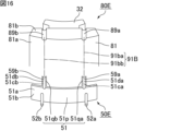
- FIG. 16 is a schematic perspective view showing the split core and terminal plate in FIG. 15 in an exploded state.
- FIG. 17 is a schematic perspective view showing a coil unit constituting an example of a stator according to Embodiment 4 of the present invention.
- FIG. 18 is a schematic perspective view showing the split core and terminal plate in FIG. 17 in an exploded state.
- FIG. 19 is a schematic perspective view showing a coil unit constituting an example of a stator according to Embodiment 5 of the present invention.
- FIG. 20 is a schematic perspective view showing the split core and terminal plate in FIG. 19 in an exploded state.
- FIG. 21 is a schematic perspective view showing a coil unit constituting an example of a stator according to Embodiment 6 of the present invention.
- FIG. 22 is a schematic perspective view showing the split core and terminal plate in FIG. 21 in an exploded state.
- FIG. 23 is a schematic cross-sectional view showing an example of a cross section of the coil unit (excluding the winding) shown in FIG. 21 along line b1-b2.
- FIG. 24 is a schematic perspective view showing a coil unit constituting an example of a stator according to Embodiment 7 of the present invention.
- FIG. 25 is a schematic perspective view showing the divided core and terminal plate in FIG. 24 in an exploded state.
- FIG. 26 is a schematic cross-sectional view showing an example of a cross section of the coil unit (excluding the winding) shown in FIG. 24 along line segment c1-c2.
- FIG. 27 is a schematic perspective view showing a coil unit constituting an example of a stator according to Embodiment 8 of the present invention.
- FIG. 28 is a schematic perspective view showing the split core and terminal plate in FIG. 27 in an exploded state.
- FIG. 29 is a schematic cross-sectional view showing an example of a cross section of the coil unit (excluding the winding) shown in FIG. 27 along line segment d1-d2.
- FIG. 30 is a schematic perspective view showing an example of a stator according to Embodiment 9 of the present invention.
- FIG. 31 is a schematic perspective view showing the coil unit in FIG. 30.
- FIG. 32 is a schematic perspective view showing an example of a motor according to Embodiment 10 of the present invention.
- FIG. 33 is a schematic perspective view showing an example of a motor according to Embodiment 11 of the present invention.
- the stator of the present invention and the motor of the present invention will be explained.
- the present invention is not limited to the following configuration, and may be modified as appropriate without departing from the gist of the present invention.
- the present invention also includes a combination of a plurality of individual preferred configurations described below.
- the stator of the present invention has an annular yoke along the circumferential direction, teeth protruding from the inner circumferential surface of the yoke in the radial direction of the yoke, and a stator core made of a molded body of magnetic powder. , a coil configured with a winding wound around the teeth, and a terminal plate provided on the outer circumferential surface of the yoke in the radial direction, the terminal plate including a plate portion and the plate portion. a terminal portion fixed to the terminal portion, and the plate portion has a first surface located on the outer peripheral surface side of the yoke in the radial direction, and a first surface located on the opposite side of the outer peripheral surface of the yoke. and two surfaces, wherein the terminal portion protrudes from at least the second surface of the plate portion, and one end of the winding wire is fixed and wound around the terminal portion. It is characterized by
- the outer circumferential surface of the yoke and the first surface of the plate portion may be fitted together at an outer circumferential side fitting portion.
- the outer peripheral surface side mating portion includes a convex portion protruding from one of the outer peripheral surface of the yoke and the first surface of the plate portion, and the outer peripheral surface of the yoke and the first surface of the plate portion.
- a concave portion recessed from the other side of the first surface of the plate portion may be interlocked with each other.
- FIG. 1 is a schematic perspective view showing an example of a stator according to Embodiment 1 of the present invention.
- the stator 20A shown in FIG. 1 includes a stator core 30A, a plurality of coils 40A, and a plurality of terminal plates 50A.
- the stator core 30A includes a yoke (also called a core back) 31 and a plurality of teeth 32.
- the direction in which the axis of the stator core extends is defined as the axial direction. Further, the direction along the outer peripheral surface of the yoke when viewed from the axial direction is defined as the circumferential direction. Furthermore, the direction perpendicular to the axial direction and in which the outer circumferential surface and the inner circumferential surface of the yoke face each other is defined as the radial direction.
- the yoke 31 is annular along the circumferential direction.
- the plurality of teeth 32 independently protrude from the inner peripheral surface of the yoke 31 in the radial direction of the yoke 31 so as to be spaced apart from each other in the circumferential direction. In this way, the plurality of teeth 32 are integrated with the yoke 31.
- the stator core 30A is composed of a molded body of magnetic powder. That is, the yoke 31 and teeth 32 of the stator core 30A are integrally formed of a molded body of magnetic powder.
- the stator core is preferably composed of a dust core.
- the stator core 30A is preferably composed of a dust core. That is, it is preferable that the yoke 31 and the teeth 32 of the stator core 30A are integrally formed of a powder magnetic core.
- the stator core 30A may be composed of a molded body of a composite material containing magnetic powder and resin instead of a powder magnetic core.
- Each of the plurality of coils 40A is composed of a winding 41 wound around the teeth 32.
- the plurality of coils 40A are each independently provided on the teeth 32 so as to be spaced apart from each other in the circumferential direction.
- Each of the plurality of coils 40A is insulated from the teeth 32, for example, via an insulating member that will be described later.
- the plurality of coils 40A include a coil configured with a U-phase winding, a coil configured with a V-phase winding, and a coil configured with a W-phase winding.
- the U-phase winding, V-phase winding, and W-phase winding are connected by star connection or delta connection.
- winding wire 41 examples include polyurethane copper wire (UEW).
- UEW polyurethane copper wire
- the plurality of terminal plates 50A are each provided on the outer peripheral surface 31a of the yoke 31 in the radial direction.
- stator 20A since the terminal plate 50A is provided on the outer peripheral surface 31a of the yoke 31, even when the terminal plate 50A is provided, the thickness of the stator 20A increases, more specifically, An increase in the axial dimension of stator 20A is suppressed.
- the terminal board 50A has a plate portion 51, a terminal portion 52a, and a terminal portion 52b.
- the plate portion 51 has a first surface 51a located on the outer peripheral surface 31a side of the yoke 31 and a second surface 51b located on the opposite side to the outer peripheral surface 31a of the yoke 31 in the radial direction.
- the plate portion 51 is preferably made of an insulating material.
- Examples of the insulating material constituting the plate portion 51 include resins such as polyphenylene sulfide (PPS).
- PPS polyphenylene sulfide
- the terminal portion 52a and the terminal portion 52b are fixed to the plate portion 51.
- the terminal portion 52a and the terminal portion 52b protrude from at least the second surface 51b of the plate portion 51.
- the direction in which the terminal portion 52a and the terminal portion 52b extend is a direction perpendicular to the axial direction.
- the direction in which the terminal portions 52a and 52b extend may be the radial direction or a direction different from the radial direction.
- the terminal portion 52a and the terminal portion 52b are spaced apart from each other in the circumferential direction.
- the terminal portion is preferably made of a conductive material.
- the terminal portions 52a and 52b are preferably made of a conductive material.
- one end 41a of the winding 41 and a terminal of a connection board, which will be described later, can be easily connected via the terminal portion 52a.
- the other end 41b of the winding 41 and a terminal of a connection board, which will be described later, can be easily connected via the terminal portion 52b.
- Examples of the conductive material constituting the terminal portions 52a and 52b include metals such as phosphor bronze.
- the terminal portion 52a and the terminal portion 52b may be made of an insulating material. In this case, it is not necessary to consider the insulation between the terminal portion 52a and the stator core 30A, and furthermore the insulation between the terminal portion 52b and the stator core 30A, so the terminal portion 52a and the terminal portion 52b can be easily fixed to the plate portion 51. Further, by integrally molding the terminal portion 52a and the terminal portion 52b with the plate portion 51, the terminal plate 50A can be easily manufactured.
- Examples of the insulating material constituting the terminal portions 52a and 52b include resins such as polyphenylene sulfide.
- the constituent materials of the terminal portion 52a and the terminal portion 52b are preferably the same, but may be different from each other.
- Examples of the three-dimensional shape of the terminal portion 52a and the terminal portion 52b include a cylindrical shape, a prismatic shape, and the like.
- the three-dimensional shapes of the terminal portion 52a and the terminal portion 52b are preferably the same, but may be different from each other.
- the terminal plate 50A is provided on the outer peripheral surface 31a of the yoke 31. That is, the terminal plate 50A is provided on the outer circumferential surface 31a of the yoke 31 such that the first surface 51a of the plate portion 51 faces the outer circumferential surface 31a of the yoke 31.
- the terminal plate 50A is preferably provided on the outer peripheral surface 31a of the yoke 31 via an insulating member (not shown). That is, it is preferable that an insulating member be interposed between the outer circumferential surface 31a of the yoke 31 and the first surface 51a of the plate portion 51. In this case, insulation between the yoke 31 and the terminal plate 50A, particularly insulation between the yoke 31 and the terminal portion 52a, and insulation between the yoke 31 and the terminal portion 52b is ensured.
- the insulating member may be an insulating film that covers at least one of the outer circumferential surface 31a of the yoke 31 and the first surface 51a of the plate portion 51.
- the outer circumferential surface 31a of the yoke 31 may be covered with an insulating film
- the first surface 51a of the plate portion 51 may be covered with an insulating film
- the outer circumferential surface 31a of the yoke 31 and the plate portion 51 and the first surface 51a may be covered with an insulating film.
- the entire surface of the stator core 30A is covered with the insulating film. Note that when the outer peripheral surface 31a of the yoke 31 is covered with an insulating film, the entire surface of the stator core 30A does not need to be covered with the insulating film.
- the entire surface of the plate portion 51 is covered with the insulating film. Note that when the first surface 51a of the plate portion 51 is covered with an insulating film, the entire surface of the plate portion 51 does not need to be covered with the insulating film.
- a method for coating target surfaces such as the outer circumferential surface 31a of the yoke 31 and the first surface 51a of the plate portion 51 with an insulating film for example, a method of coating the target surfaces with an insulating material by a coating method such as electrodeposition coating is used. etc.
- the insulating member may be an insulating sheet formed in advance from an insulating material.
- the insulating sheet is disposed at least between the outer circumferential surface 31a of the yoke 31 and the first surface 51a of the plate portion 51.
- the first surface 51a of the plate portion 51 does not need to be covered with an insulating film.
- the terminal portion 52a and the terminal portion 52b are exposed from the first surface 51a of the plate portion 51 as described later, the terminal portion 52a and the terminal portion 52b exposed from the first surface 51a of the plate portion 51 are Preferably, the exposed portion is covered with an insulating film.
- One end 41a of the winding 41 is fixed and wound around the terminal 52a. Thereby, one end 41a of the winding 41 is led out to the terminal plate 50A.
- One end portion 41a of the winding 41 may be wound around the terminal portion 52a and then fixed to the terminal portion 52a by soldering or the like.
- one end portion 41a of the winding 41 may be wound around the terminal portion 52a and then fixed to the terminal portion 52a and a terminal of a connection board to be described later by soldering or the like.
- the other end 41b of the winding 41 is fixed and wound around the terminal portion 52b. In this case, the other end 41b of the winding 41 is led out to the terminal plate 50A.
- the other end 41b of the winding 41 may be wound around the terminal portion 52b and then fixed to the terminal portion 52b by soldering or the like.
- the other end portion 41b of the winding 41 may be wound around the terminal portion 52b and then fixed to the terminal portion 52b and a terminal of a connection board to be described later by soldering or the like.
- stator 20A it is sufficient that there is at least one coil 40A fixed with one end 41a of the winding 41 wound around the terminal part 52a, and for all the coils 40A, the winding 41 is fixed. It is preferable that one end portion 41a is fixed in a state where it is wrapped around the terminal portion 52a.
- one end 41a of the winding 41 is fixed in a state wound around the terminal part 52a, and the other end 41b of the winding 41 is fixed. It is particularly preferable that it is fixed in a state where it is tied around the terminal portion 52b.
- the one end 41a of the winding 41 is fixed.
- the coil 40A that is fixed in a state where it is wound around the terminal part 52a and the other end part 41b of the winding 41 is not fixed in a state in which it is wound around the terminal part 52b.
- the coil 40A is electrically led out, for example, electrically connected to a wiring board to be described later. Electrical derivation of the coil 40A for this purpose is realized.
- stator 20A since the terminal plate 50A is provided on the outer circumferential surface 31a of the yoke 31, even when the terminal plate 50A is provided, the thickness of the stator 20A is increased, more specifically, , an increase in the axial dimension of the stator 20A is suppressed.
- stator 20A it is possible to electrically lead out the coil 40A while suppressing an increase in thickness.
- stator 20A When manufacturing the stator 20A, as will be described later, in order to provide the terminal plate 50A on the outer peripheral surface 31a of the yoke 31, there is no need to perform additional processing on the stator core 30A after molding. Therefore, a decrease in manufacturing efficiency of the stator 20A is suppressed.
- stator 20A When manufacturing the stator 20A, as will be described later, in order to provide the terminal plate 50A on the outer peripheral surface 31a of the yoke 31, there is no need to perform additional processing on the stator core 30A after molding. Therefore, when manufacturing the stator 20A, the stator core 30A is not damaged, and as a result, a decrease in the strength of the stator 20A (more specifically, the stator core 30A) is suppressed.
- the provision of the terminal plate 50A does not reduce the space factor of the coil 40A (winding 41). . This ensures the output density of the motor incorporating the stator 20A.
- the terminal plate is preferably provided along a boundary between the outer peripheral surface of the yoke and an end surface of the yoke in the axial direction of the stator core.
- the terminal plate 50A is preferably provided along the boundary between the outer peripheral surface 31a of the yoke 31 and the end surface 31b of the yoke 31 in the axial direction of the stator core 30A. In this case, the terminal portion 52a and the terminal portion 52b become closer to the main body of the coil 40A, making it easier to electrically lead out the coil 40A.
- stator of the present invention a stator in which a plurality of coil units are arranged in an annular manner in the circumferential direction will be cited, and the manner in which the terminal plate is installed on the outer circumferential surface of the yoke in each coil unit will be described.
- the stator of the present invention may include a plurality of coil units arranged in an annular manner in the circumferential direction, and each of the plurality of coil units independently has a divided core formed by dividing the stator core in the circumferential direction. , the above-mentioned coil, and the above-mentioned terminal board.
- the stator 20A shown in FIG. 1 is made up of a plurality of coil units 70A arranged in a ring shape in the circumferential direction.
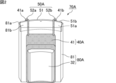
- FIG. 2 is a schematic perspective view showing the coil unit in FIG. 1 viewed from the inside in the radial direction.
- FIG. 3 is a schematic perspective view showing the coil unit in FIG. 1 viewed from the outside in the radial direction.
- FIG. 4 is a schematic perspective view showing the split core in FIG. 2.
- FIG. 5 is a schematic perspective view showing the split core and terminal plate in FIG. 3 in an exploded state.
- FIG. 6 is a schematic perspective view showing the terminal plate in FIG. 5 viewed from the inside in the radial direction.
- the coil is not shown in order to make the structure of the split core and the terminal plate easier to understand. For the same reason, the coils are not shown in the subsequent drawings in which the split cores and terminal plates are shown in an exploded state.
- the coil unit 70A shown in FIGS. 2 and 3 includes a split core 80A, a coil 40A, and a terminal plate 50A.
- the split core 80A is formed by dividing the stator core 30A in the circumferential direction.
- the stator core 30A is made up of a plurality of divided cores 80A arranged in an annular manner in the circumferential direction.
- the split core 80A includes a split yoke 81 and teeth 32.
- the divided yoke 81 is formed by dividing the yoke 31 in the circumferential direction.
- the teeth 32 protrude from the inner peripheral surface of the split yoke 81 in the radial direction. In this way, the teeth 32 are integrated with the split yoke 81.
- the split core 80A is composed of a molded body of magnetic powder. That is, the split yoke 81 and teeth 32 of the split core 80A are integrally formed of a molded body of magnetic powder.
- the outer periphery of the split core 80A along the circumferential direction may be curved or linear, for example, The shape may be a combination of a curved shape and a straight shape.
- the mode in which the split yokes 81 whose outer peripheries when viewed from the axial direction have the above-mentioned shape are lined up in the circumferential direction is included in the mode in which the yoke 31 is annular along the circumferential direction.
- the teeth 32 are preferably thinner on the split yoke 81 side than on the opposite side to the split yoke 81 in at least one of the axial and circumferential directions. In the example shown in FIG. 4, the teeth 32 are thinner in the circumferential direction on the side of the split yoke 81 than on the side opposite to the split yoke 81.
- the teeth 32 are thinner in at least one of the axial and circumferential directions on the yoke 31 side than on the opposite side to the yoke 31.
- the teeth 32 are thinner in at least one of the axial and circumferential directions on the yoke 31 side than on the opposite side to the yoke 31.
- the thinner part can be used as the winding axis of the coil 40A.
- the number of turns of the coil 40A can be increased.
- the magnetic flux passing through the coil 40A tends to increase, and thus the output torque of the motor tends to improve.
- the coil 40A is provided on the teeth 32 of the split core 80A.
- the terminal plate 50A is fixed to the outer peripheral surface 81a of the split yoke 81 of the split core 80A in the radial direction.
- the terminal portion 52a and the terminal portion 52b protrude from the second surface 51b of the plate portion 51. More specifically, the terminal portion 52a and the terminal portion 52b protrude from the second surface 51b of the plate portion 51 toward the side opposite to the first surface 51a.
- the terminal portion 52a and the terminal portion 52b penetrate the plate portion 51 and are exposed from the first surface 51a of the plate portion 51.
- the terminal portion 52a and the terminal portion 52b do not protrude from the first surface 51a of the plate portion 51. More specifically, the terminal portion 52a and the terminal portion 52b do not protrude from the first surface 51a of the plate portion 51 toward the side opposite to the second surface 51b.
- At least one of the terminal portion 52a and the terminal portion 52b may protrude from the first surface 51a of the plate portion 51. More specifically, at least one of the terminal portion 52a and the terminal portion 52b may protrude from the first surface 51a of the plate portion 51 toward the side opposite to the second surface 51b.
- the split yoke 81 of the split core 80A is provided with a recess 86a that is depressed from the outer peripheral surface 81a.
- the recess 86a is provided at the periphery of the outer circumferential surface 81a of the split yoke 81. More specifically, the recess 86a is provided from the outer peripheral surface 81a of the split yoke 81 to the end surface 81b of the split yoke 81 in the axial direction.
- the three-dimensional shape of the recess 86a is not limited to the embodiment shown in FIG.
- the plate portion 51 of the terminal board 50A is provided with a protrusion 55a that protrudes from the first surface 51a.
- the convex portion 55a is provided at the periphery of the first surface 51a of the plate portion 51.
- the three-dimensional shape of the convex portion 55a is not limited to the embodiments shown in FIGS. 5 and 6.
- the outer circumferential surface 81a of the split yoke 81 and the first surface 51a of the plate portion 51 are fitted together at the outer circumferential side fitting portion 90A, as shown in FIG.
- the outer peripheral surface side fitting portion 90A is formed by fitting the concave portion 86a and the convex portion 55a. That is, in the coil unit 70A, the terminal plate 50A is fixed to the outer circumferential surface 81a of the split yoke 81 because the concave portion 86a and the convex portion 55a are fitted together.
- the outer circumferential surface 81a of the split yoke 81 and the first surface 51a of the plate part 51 are fitted together at the outer circumferential surface side fitting part 90A, so that the terminal plate 50A is connected to the split yoke. 81, and positioning of the terminal plate 50A in the axial and circumferential directions becomes easy.
- a recess 86a is provided on the outer peripheral surface 81a of the split yoke 81, and the recess 86a is molded at the same time as the split core 80A is molded. That is, when manufacturing the coil unit 70A, there is no need to perform additional processing on the molded split core 80A in order to provide the recess 86a on the outer peripheral surface 81a of the split yoke 81. Therefore, a decrease in manufacturing efficiency of the coil unit 70A is suppressed.
- the split core 80A is not damaged when the recess 86a is provided on the outer peripheral surface 81a of the split yoke 81, so the coil unit 70A (more specifically, the split core 80A) is Decrease in strength is suppressed.
- stator 20A in which a plurality of coil units 70A are arranged annularly in the circumferential direction, a decrease in manufacturing efficiency and a decrease in strength are suppressed even if the recess 86a is provided.
- the recess 86a provided in the outer circumferential surface 81a of the split yoke 81 may be shallower than the screw hole described in Patent Document 1, but it can connect the first surface 51a of the plate portion 51 and the outer circumferential surface 81a of the split yoke 81. It works when it matches. Therefore, in the coil unit 70A, even if the recess 86a is provided in the outer circumferential surface 81a of the split yoke 81, the influence on the magnetic properties is minimized. Therefore, in the stator 20A in which a plurality of coil units 70A are arranged annularly in the circumferential direction, even if the recess 86a is provided, the influence on the magnetic properties can be suppressed to a minimum.
- the outer end of the terminal plate 50A is not located outside the outer end of the split yoke 81 in the axial direction. In this case, even when the terminal plate 50A is provided, an increase in the thickness of the coil unit 70A is sufficiently suppressed.
- the outer end of the terminal plate 50A is wider than the outer end of the split yoke 81 (more specifically, the outer peripheral surface 81a of the split yoke 81) in the circumferential direction. Preferably, it is not located on the outside. In this case, compared to the case where the outer end of the terminal plate 50A is located outside the outer end of the split yoke 81 in the circumferential direction, the plurality of coil units 70A can be manufactured without interfering with each other when manufacturing the stator 20A. It becomes easier to arrange them in a ring shape in the circumferential direction.
- the outer end of the terminal plate 50A is not located outside the outer end of the split yoke 81 in the circumferential direction. On the other hand, it may be located inside as shown in FIGS. 2 and 3, or may be located at the same position.
- the outer circumferential surface side engagement portion that engages the outer circumferential surface of the yoke and the first surface of the plate portion is not limited to the embodiment shown in FIG. 5. Other aspects of the outer circumferential surface-side engaging portion that engages the outer circumferential surface of the yoke and the first surface of the plate portion will be described below.
- FIG. 7 is a schematic perspective view showing a coil unit that constitutes an example of a stator according to a modification of Embodiment 1 of the present invention.
- FIG. 8 is a schematic perspective view showing the divided core and terminal plate in FIG. 7 in an exploded state.
- the coil unit 70B shown in FIG. 7 includes a split core 80B, a coil 40A, and a terminal plate 50B.
- the split yoke 81 of the split core 80B is provided with a recess 86b that is depressed from the outer peripheral surface 81a.
- the recess 86b is provided on the outer peripheral surface 81a of the split yoke 81 along the axial direction.
- the recess 86b may be provided from one end to the other end of the outer circumferential surface 81a of the split yoke 81 in the axial direction.
- the outline of the recess 86b when viewed from the axial direction may be, for example, curved, linear, or a combination of curved and linear. In the example shown in FIG. 8, the outline of the recess 86b when viewed from the axial direction is curved.
- the plate portion 51 of the terminal board 50B is provided with a protrusion 55b that protrudes from the first surface 51a.
- the convex portion 55b is provided on the first surface 51a of the plate portion 51 along the axial direction. More specifically, the convex portion 55b is provided from one end to the other end in the axial direction of the first surface 51a of the plate portion 51 so as to have a shape along the concave portion 86b.
- the outline of the convex portion 55b when viewed from the axial direction may be, for example, curved, linear, or a combination of curved and linear.
- the outline of the convex portion 55b when viewed from the axial direction is curved.
- the outer circumferential surface 81a of the split yoke 81 and the first surface 51a of the plate part 51 are fitted together at the outer circumferential side fitting part 90B.
- the outer peripheral surface side fitting portion 90B is formed by fitting the recessed portion 86b and the convex portion 55b. That is, in the coil unit 70B, the terminal plate 50B is fixed to the outer circumferential surface 81a of the split yoke 81 by fitting the concave portion 86b and the convex portion 55b.
- the outer circumferential surface 81a of the split yoke 81 and the first surface 51a of the plate part 51 are fitted together at the outer circumferential surface side fitting part 90B, so that the terminal plate 50B is attached to the split yoke. 81, and positioning of the terminal plate 50B in the circumferential direction becomes easy.
- a recess 86b is provided on the outer peripheral surface 81a of the split yoke 81, and the recess 86b is molded at the same time as the split core 80B is molded. That is, when manufacturing the coil unit 70B, there is no need to perform additional processing on the molded split core 80B in order to provide the recess 86b on the outer peripheral surface 81a of the split yoke 81. Therefore, a decrease in the manufacturing efficiency of the coil unit 70B is suppressed, and furthermore, a decrease in the strength of the coil unit 70B (more specifically, the split core 80B) is suppressed.
- the configuration of the outer circumferential surface side fitting portion that fits the outer circumferential surface of the yoke (divided yoke) and the first surface of the plate portion is the above-described embodiment 1 and a modification of embodiment 1.
- Other configurations may also be used.
- the outer circumferential surface side mating portion has a structure as shown in FIGS. 5 and 8, in which a concave portion recessed from the outer circumferential surface of the split yoke and a convex portion protruding from the first surface of the plate portion are mated.
- a configuration in which a convex portion protruding from the outer circumferential surface of the split yoke and a concave portion recessed from the first surface of the plate portion are fitted together may be used.
- the position of the outer peripheral surface side mating portion is not limited to the embodiments shown in FIGS. 5 and 8.
- the total number of outer peripheral surface side mating portions is not limited to the embodiments shown in FIGS. 5 and 8.
- one outer circumferential surface side fitting part may be provided for one set of the divided yoke and the plate part, as shown in FIGS. 5 and 8, or a plurality of them may be provided.
- the positional relationship of these outer circumferential surface side mating parts is not particularly limited.
- the plurality of outer peripheral surface side fitting portions may be provided so as to be spaced apart in the axial direction, or may not be provided so as to be spaced apart in the axial direction.
- the plurality of outer peripheral surface side fitting portions may be provided so as to be spaced apart in the circumferential direction, or may not be provided so as to be spaced apart in the circumferential direction.
- the outer peripheral surface side mating portion does not need to exist. That is, the outer circumferential surface of the yoke (divided yoke) and the first surface of the plate part do not need to be fitted together. In this case, for example, the outer peripheral surface of the yoke (divided yoke) and the first surface of the plate portion may be joined as described later.
- the outer peripheral surface side fitting portion may overlap the terminal portion in the direction in which the terminal portion extends.
- the convex part is provided so as to protrude from the first surface of the plate part in the direction in which the terminal part extends, and the concave part is provided in the yoke.
- the terminal portion is recessed from the outer circumferential surface in the direction in which the terminal portion extends.
- FIG. 9 is a schematic perspective view showing a coil unit that constitutes an example of a stator according to Embodiment 2 of the present invention.
- FIG. 10 is a schematic perspective view showing the divided core and terminal plate in FIG. 9 in an exploded state.
- FIG. 11 is a schematic cross-sectional view showing an example of a cross section of the coil unit (excluding the winding) shown in FIG. 9 along line segment a1-a2.
- the coil unit 70C shown in FIG. 9 includes a split core 80C, a coil 40A, and a terminal plate 50C.
- the split yoke 81 of the split core 80C is provided with a recess 86c that is depressed from the outer peripheral surface 81a in the direction in which the terminal portion 52a extends. Further, the split yoke 81 of the split core 80C is provided with a recess 86d that is depressed from the outer peripheral surface 81a in the direction in which the terminal portion 52b extends.
- the recess 86c and the recess 86d are spaced apart from each other in the circumferential direction.
- the three-dimensional shapes of the recess 86c and the recess 86d are not limited to the embodiment shown in FIG. 10, respectively.
- the three-dimensional shapes of the recess 86c and the recess 86d may be the same or different.
- the plate portion 51 of the terminal board 50C is provided with a protrusion 55c that protrudes from the first surface 51a in the direction in which the terminal portion 52a extends. Further, the plate portion 51 of the terminal board 50C is provided with a convex portion 55d that protrudes from the first surface 51a in the direction in which the terminal portion 52b extends.
- the convex portion 55c overlaps the terminal portion 52a in the direction in which the terminal portion 52a extends.
- the convex portion 55d overlaps the terminal portion 52b in the direction in which the terminal portion 52b extends.
- the convex portion 55c and the convex portion 55d are spaced apart from each other in the circumferential direction.
- the three-dimensional shapes of the convex portion 55c and the convex portion 55d are not limited to the embodiment shown in FIG. 10, respectively.
- the three-dimensional shapes of the convex portion 55c and the convex portion 55d may be the same or different from each other.
- the outer circumference side fitting part 90C includes an outer circumference side fitting part 90ca formed by fitting the recess 86c and the protrusion 55c, and an outer circumference side fitting part 90cb formed by fitting the recess 86d and the protrusion 55d. , contains.
- the terminal plate 50C is fixed to the outer circumferential surface 81a of the split yoke 81 because the concave portion 86c and the convex portion 55c are engaged, and the concave portion 86d and the convex portion 55d are engaged. There is.
- the recessed portion 86c and the convex portion 55c overlap in the direction in which the terminal portion 52a extends in the outer peripheral surface side mating portion 90ca. Furthermore, in the outer circumferential surface side mating portion 90C, the recessed portion 86d and the convex portion 55d overlap in the direction in which the terminal portion 52b extends. On the other hand, as described above, in the terminal board 50C, the convex portion 55c and the terminal portion 52a overlap in the direction in which the terminal portion 52a extends. Further, in the terminal plate 50C, the convex portion 55d and the terminal portion 52b overlap in the direction in which the terminal portion 52b extends.
- the outer peripheral surface side mating portion 90ca overlaps the terminal portion 52a in the direction in which the terminal portion 52a extends.
- the outer circumferential surface side mating portion 90cb overlaps the terminal portion 52b in the direction in which the terminal portion 52b extends.
- the outer circumferential surface 81a of the split yoke 81 and the first surface 51a of the plate part 51 are fitted together at the outer circumferential surface side fitting part 90C, so that the terminal plate 50C is attached to the split yoke.
- the terminal board 50C can be easily fixed to the outer circumferential surface 81a of the terminal board 81, and the terminal board 50C can be easily positioned.
- the terminal plate 50C is attached to the outer circumferential surface of the divided yoke 81 by using only the two outer circumferential surface side mating portions, the outer circumferential surface side mating portion 90ca and the outer circumferential surface side mating portion 90cb. 81a, and positioning of the terminal plate 50C becomes possible.
- a recess 86c and a recess 86d are provided on the outer peripheral surface 81a of the split yoke 81, and the recess 86c and the recess 86d are molded at the same time as the split core 80C is molded. That is, when manufacturing the coil unit 70C, there is no need to perform additional processing on the molded split core 80C in order to provide the recess 86c and the recess 86d on the outer peripheral surface 81a of the split yoke 81. Therefore, a decrease in the manufacturing efficiency of the coil unit 70C is suppressed, and further a decrease in the strength of the coil unit 70C (more specifically, the split core 80C) is suppressed.
- the terminal board 50C since the protrusion 55c is provided at a position overlapping the terminal part 52a in the direction in which the terminal part 52a extends, compared to the case where the protrusion 55c is not provided, as shown in FIG. In addition, it is possible to increase the size of the terminal portion 52a embedded in the plate portion 51 in the direction in which the terminal portion 52a extends. Thereby, in the terminal board 50C, the terminal portion 52a is firmly fixed to the plate portion 51. Since the terminal portion 52a firmly fixed to the plate portion 51 does not easily wobble, the work efficiency when winding one end 41a of the winding 41 around the terminal portion 52a can be easily improved.
- FIG. 11 shows a cross section at a position where the terminal portion 52a and the convex portion 55c overlap in the coil unit 70C
- the cross section at the position where the terminal portion 52b and the convex portion 55d overlap may also be the same as that in FIG. preferable.
- the plate portion includes a first plate portion facing the outer peripheral surface of the yoke, and a portion of the first plate portion facing the end surface of the yoke in the axial direction of the stator core.
- the second plate portion may have an extending second plate portion, and the first plate portion may have the first surface and the second surface, and the second plate portion may have the first surface and the second surface.
- the yoke may have a third surface located on the end surface side of the yoke, and a fourth surface located on the opposite side to the end surface of the yoke.
- the end surface of the yoke and the third surface of the second plate part may be fitted together at an end side fitting part.
- the end surface side fitting portion includes a convex portion protruding from one of the end surface of the yoke and the third surface of the second plate portion, and the end surface of the yoke and the third surface of the second plate portion.
- a concave portion recessed from the other side of the third surface of the second plate portion may be fitted together.
- FIG. 12 is a schematic perspective view showing a coil unit that constitutes an example of a stator according to Embodiment 3 of the present invention.
- FIG. 13 is a schematic perspective view showing the divided core and terminal plate in FIG. 12 in an exploded state.
- FIG. 14 is a schematic perspective view showing the terminal plate in FIG. 13 viewed from the inside in the radial direction.
- the coil unit 70D shown in FIG. 12 includes a split core 80D, a coil 40A, and a terminal plate 50D.
- the split yoke 81 of the split core 80D is provided with a recess 86e that is depressed from the end surface 81b in the axial direction.
- the three-dimensional shape of the recess 86e is not limited to the embodiment shown in FIG. 13.
- the plate portion 51 of the terminal board 50D includes a first plate portion 51p and a second plate portion 51q.
- the first plate portion 51p faces the outer peripheral surface 81a of the split yoke 81.
- the first plate portion 51p has a first surface 51a and a second surface 51b.
- the second plate portion 51q extends from a portion of the first plate portion 51p so as to face the end surface 81b of the split yoke 81.
- the direction in which the second plate portion 51q extends is preferably a direction perpendicular to the axial direction.
- the direction in which the second plate portion 51q extends may be the radial direction or a direction different from the radial direction.
- the second plate portion 51q has a third surface 51c located on the end surface 81b side of the split yoke 81, and a fourth surface 51d located on the opposite side to the end surface 81b of the split yoke 81.
- the second plate portion 51q is provided with a protrusion 55e that protrudes from the third surface 51c.
- the three-dimensional shape of the convex portion 55e is not limited to the embodiments shown in FIGS. 13 and 14.
- the end face 81b of the split yoke 81 and the third face 51c of the second plate portion 51q are fitted together at the end face side fitting part 91A.
- the end surface side mating portion 91A is formed by mating the concave portion 86e and the convex portion 55e. That is, in the coil unit 70D, the terminal plate 50D is fixed to the end surface 81b of the split yoke 81 and provided on the outer circumferential surface 81a of the split yoke 81 because the recess 86e and the protrusion 55e are fitted together.
- the end face 81b of the split yoke 81 and the third face 51c of the second plate portion 51q are fitted together at the end face side fitting portion 91A, so that the terminal plate 50D is connected to the split yoke.
- the terminal plate 50D can be easily fixed to the end surface 81b of the terminal plate 81, and the terminal plate 50D can be easily positioned in the axial direction.
- a recess 86e is provided in the end face 81b of the split yoke 81, and the recess 86e is molded at the same time as the split core 80D is molded. That is, when manufacturing the coil unit 70D, there is no need to perform additional processing on the molded split core 80D in order to provide the recess 86e in the end surface 81b of the split yoke 81. Therefore, a decrease in the manufacturing efficiency of the coil unit 70D is suppressed, and further a decrease in the strength of the coil unit 70D (more specifically, the split core 80D) is suppressed.
- the second plate portion 51q is provided on the end surface 81b of the split yoke 81, there is a concern that the thickness of the coil unit 70D will increase.
- the thickness of the second plate portion 51q more specifically, the axial dimension of the second plate portion 51q is sufficiently smaller than the thickness of the bus bar described in Patent Document 1, for example.
- the second plate portion 51q has almost no effect on the increase in the thickness of the coil unit 70D.
- the thickness of the second plate portion 51q when the thickness of the second plate portion 51q is equal to or less than the diameter of the winding 41 (for example, 0.3 mm or more and 0.5 mm or less), the increase in the thickness of the coil unit 70D due to the second plate portion 51q is The impact is sufficiently suppressed.
- the thickness of the second plate portion 51q may be larger than the diameter of the winding 41 as long as it does not affect the increase in the thickness of the coil unit 70D.
- the second plate portion 51q may be accommodated in a recess provided in the end surface 81b of the split yoke 81 in the axial direction. In this case, the influence of the second plate portion 51q on the increase in the thickness of the coil unit 70D is suppressed as much as possible.
- the entire second plate portion 51q is accommodated in a recess provided in the end surface 81b of the split yoke 81 in the axial direction. That is, it is preferable that the entire thickness of the second plate part 51q is equal to or less than the depth of the recess in which the second plate part 51q is accommodated.
- a portion of the second plate portion 51q may be accommodated in a recess provided in the end surface 81b of the split yoke 81.
- the thickness of a portion of the second plate portion 51q may be less than or equal to the depth of the recess in which the second plate portion 51q is accommodated.
- the end surface side fitting portion that fits the end surface of the yoke and the third surface of the second plate portion is not limited to the embodiment shown in FIG. 13. Other aspects of the end surface side fitting portion that fits the end surface of the yoke and the third surface of the second plate portion will be described below.
- FIG. 15 is a schematic perspective view showing a coil unit constituting an example of a stator of a modification of Embodiment 3 of the present invention.
- FIG. 16 is a schematic perspective view showing the split core and terminal plate in FIG. 15 in an exploded state.
- the coil unit 70E shown in FIG. 15 includes a split core 80E, a coil 40A, and a terminal plate 50E.
- the plate portion 51 of the terminal board 50E includes a first plate portion 51p, a second plate portion 51qa, and a second plate portion 51qb.
- the second plate portion 51qa extends from a part of the first plate portion 51p so as to face the end surface 81b of the split yoke 81.
- the second plate portion 51qb extends from a portion of the first plate portion 51p to face the end surface 81b of the split yoke 81 at a position spaced apart from the second plate portion 51qa in the circumferential direction.
- the directions in which the second plate portion 51qa and the second plate portion 51qb extend may be the same (may be parallel to each other) or different from each other (they may not be parallel to each other). .
- the second plate portion 51qa has a third surface 51ca located on the end surface 81b side of the split yoke 81, and a fourth surface 51da located on the opposite side to the end surface 81b of the split yoke 81.
- the second plate portion 51qb has a third surface 51cb located on the end surface 81b side of the split yoke 81, and a fourth surface 51db located on the opposite side to the end surface 81b of the split yoke 81.
- the end surface 81b of the split yoke 81 is provided with a yoke groove 89a along the direction in which the second plate portion 51qa extends. Furthermore, the end surface 81b of the split yoke 81 is provided with a yoke groove 89b along the direction in which the second plate portion 51qb extends.
- the yoke groove 89a is preferably provided from one end to the other end of the end surface 81b of the split yoke 81 in the direction in which the second plate portion 51qa extends. Further, the yoke groove 89b is preferably provided from one end to the other end of the end surface 81b of the split yoke 81 in the direction in which the second plate portion 51qb extends.
- the three-dimensional shapes of the yoke groove 89a and the yoke groove 89b are not limited to the embodiment shown in FIG. 16, respectively.
- the three-dimensional shapes of the yoke groove 89a and the yoke groove 89b may be the same or different from each other.
- the end surface 81b of the split yoke 81 and the third surfaces of the second plate part 51qa and the second plate part 51qb are fitted together at the end face side fitting part 91B.
- the end face side fitting part 91B is an end face side fitting part 91ba formed by fitting the yoke groove 89a and the second plate part 51qa, and an end face side fitting part 91ba formed by fitting the yoke groove 89b and the second plate part 51qb. 91bb.
- the terminal plate 50E is connected to the end surface of the split yoke 81. It is provided on the outer peripheral surface 81a of the split yoke 81 while being fixed to the split yoke 81b.
- the end surface 81b of the split yoke 81 and the third surfaces of the second plate section 51qa and the second plate section 51qb are engaged with each other at the end surface side engagement section 91B.
- the terminal plate 50E is easily fixed to the end surface 81b of the split yoke 81, and the positioning of the terminal plate 50E in the axial direction becomes easy.
- a yoke groove 89a and a yoke groove 89b are provided on the end surface 81b of the split yoke 81, but the yoke groove 89a and the yoke groove 89b are formed at the same time as the split core 80E is formed. That is, when manufacturing the coil unit 70E, there is no need to perform additional processing on the molded split core 80E in order to provide the yoke grooves 89a and 89b on the end face 81b of the split yoke 81. Therefore, a decrease in the manufacturing efficiency of the coil unit 70E is suppressed, and further a decrease in the strength of the coil unit 70E (more specifically, the split core 80E) is suppressed.
- the second plate portion 51qa is accommodated in the yoke groove 89a, and the second plate portion 51qb is accommodated in the yoke groove 89b. Also, the influence of the second plate portion 51qb on the increase in the thickness of the coil unit 70E is suppressed as much as possible.
- the entire second plate portion 51qa is accommodated in the yoke groove 89a, and the entire second plate portion 51qb is accommodated in the yoke groove 89b.
- the fourth surface of the second plate portion may be provided with a guide groove extending in the direction in which the second plate portion extends, and the winding wire may be connected to the winding at one end side.
- the guide groove may extend toward the terminal portion so as to pass through the guide groove.
- a guide groove 59a along the direction in which the second plate portion 51qa extends is provided on the fourth surface 51da of the second plate portion 51qa. Furthermore, a guide groove 59b along the direction in which the second plate part 51qb extends is provided on the fourth surface 51db of the second plate part 51qb.
- the winding 41 extends toward the terminal portion 52a so as to pass through the guide groove 59a on the one end 41a side. That is, the guide groove 59a is used as a groove for arranging the winding 41 when leading out the one end 41a of the winding 41 to the terminal part 52a.
- the winding 41 extends toward the terminal portion 52a so as to pass through the guide groove 59a on the one end 41a side.
- the one end 41a side of the winding 41 is connected to the boundary between the outer peripheral surface 81a and the end surface 81b of the split yoke 81, and Since the boundary between the inner circumferential surface and the end surface 81b can be avoided, breakdown of the insulation coating of the winding 41 is prevented.
- the winding 41 extends toward the terminal portion 52b so as to pass through the guide groove 59b on the other end 41b side. That is, the guide groove 59b is used as a groove for arranging the winding 41 when leading the other end 41b of the winding 41 to the terminal portion 52b.
- the winding 41 extends toward the terminal portion 52b so as to pass through the guide groove 59b on the other end 41b side, so that the other end 41b of the winding 41 is led out to the terminal portion 52b.
- the other end 41b side of the winding 41 avoids the boundary between the outer circumferential surface 81a and the end surface 81b of the split yoke 81 and the boundary between the inner circumferential surface and the end surface 81b of the split yoke 81, the winding 41 is prevented from being destroyed.
- the configuration of the end face side fitting part that fits the end face of the yoke (divided yoke) and the third face of the second plate part is the above-described third embodiment and a modification of the third embodiment.
- Other configurations may also be used.
- the end surface side mating portion has a configuration as shown in FIG. 13, that is, a configuration in which a concave portion recessed from the end surface of the split yoke and a convex portion protruding from the third surface of the second plate portion are mated.
- a configuration may be adopted in which a convex portion protruding from the end surface of the split yoke and a concave portion recessed from the third surface of the second plate portion are fitted together.
- the position of the end surface side mating portion is not limited to the embodiments shown in FIGS. 13 and 16.
- end face side mating parts are not limited to the embodiments shown in FIGS. 13 and 16. In other words, one end face side mating part may be provided for one set of divided yoke and plate part as shown in FIG. 13, or two end face side fitting parts may be provided as shown in FIG. Alternatively, three or more may be provided.
- the positional relationship of these end face side mating parts is not particularly limited.
- the plurality of end face side fitting parts may be provided so as to be spaced apart in the circumferential direction as shown in FIG. 16, or may not be provided so as to be spaced apart in the circumferential direction.
- the plurality of end face side fitting portions may be provided so as to be spaced apart in the radial direction, or may not be provided so as to be spaced apart in the radial direction.
- the end surface side mating portion does not need to exist. That is, the end surface of the yoke (divided yoke) and the third surface of the second plate part do not need to be fitted together. In this case, for example, the end surface of the yoke (divided yoke) and the third surface of the second plate portion may be joined.
- stator of the present invention the outer circumferential surface of the yoke and the first surface of the plate portion may be joined.
- a stator that is different from the stator of Embodiment 1 of the present invention in this respect will be described below as a stator of Embodiment 4 of the present invention.
- FIG. 17 is a schematic perspective view showing a coil unit that constitutes an example of a stator according to Embodiment 4 of the present invention.
- FIG. 18 is a schematic perspective view showing the split core and terminal plate in FIG. 17 in an exploded state.
- the coil unit 70F shown in FIG. 17 includes a split core 80F, a coil 40A, and a terminal plate 50F.
- the outer peripheral surface 81a of the split yoke 81 and the first surface 51a of the plate portion 51 are joined. That is, the terminal plate 50F is fixed to the outer circumferential surface 81a of the split yoke 81 at a joint (not shown).
- Examples of the bonding portion include adhesives and the like.
- the terminal plate 50F is easily fixed to the outer circumferential surface 81a of the split yoke 81. Therefore, positioning of the terminal plate 50F becomes easy.
- the terminal plate 50F can be fixed to the outer circumferential surface 81a of the split yoke 81 with a simple structure that does not use a mating part as shown in FIG. It becomes possible to position the terminal plate 50F.
- the outer circumferential surface of the split yoke and the first surface of the plate part are as follows. In addition to being mated, they may also be joined.
- the end face of the split yoke and the third surface of the plate part may be joined in addition to being mated.
- the outer circumferential surface of the yoke includes a first outer circumferential surface, a second outer circumferential surface located inside the first outer circumferential surface in the radial direction, the first outer circumferential surface and the second outer circumferential surface. It may have a stepped surface connecting the outer circumferential surface, and the terminal board may be provided on the stepped surface.
- a stator that is different from the stator of Embodiment 1 of the present invention in this respect will be described below as a stator of Embodiment 5 of the present invention.
- FIG. 19 is a schematic perspective view showing a coil unit that constitutes an example of a stator according to Embodiment 5 of the present invention.
- FIG. 20 is a schematic perspective view showing the split core and terminal plate in FIG. 19 in an exploded state.
- the coil unit 70G shown in FIG. 19 includes a split core 80G, a coil 40A, and a terminal plate 50F.
- the terminal plate 50F of the coil unit 70G has the same configuration as the terminal plate 50F of the coil unit 70F.
- the outer circumferential surface 81a of the split yoke 81 has a first outer circumferential surface 81aa, a second outer circumferential surface 81ab, and a stepped surface 81ac.
- the first outer circumferential surface 81aa of the split yoke 81 is located on the opposite side of the end surface 81b than the second outer circumferential surface 81ab in the axial direction (lower in the axial direction in FIG. 20).
- first outer circumferential surface 81aa of the split yoke 81 may be located closer to the end surface 81b than the second outer circumferential surface 81ab in the axial direction (in FIG. 20, upward in the axial direction).
- the second outer circumferential surface 81ab of the split yoke 81 is located inside the first outer circumferential surface 81aa in the radial direction. That is, when viewed from the axial direction, the second outer circumferential surface 81ab of the split yoke 81 is shifted inward in the radial direction with respect to the first outer circumferential surface 81aa.
- the step surface 81ac of the split yoke 81 connects the first outer circumferential surface 81aa and the second outer circumferential surface 81ab.
- the step surface 81ac of the split yoke 81 extends in the circumferential direction. More specifically, the stepped surface 81ac of the split yoke 81 extends from one end to the other end in the circumferential direction of the outer peripheral surface 81a.
- the step surface 81ac of the split yoke 81 does not need to extend from one end to the other end in the circumferential direction of the outer peripheral surface 81a.
- the stepped surface 81ac of the split yoke 81 may be provided in a part of the path from one end to the other end in the circumferential direction of the outer peripheral surface 81a.
- the terminal plate 50F is provided on the step surface 81ac of the split yoke 81.
- the step surface 81ac of the split yoke 81 functions as a structure for positioning the terminal board 50F in the axial direction. That is, in the coil unit 70G, the stepped surface 81ac of the split yoke 81 facilitates positioning of the terminal plate 50F in the axial direction.
- the terminal plate 50F is provided on the stepped surface 81ac of the split yoke 81, even when the terminal plate 50F is provided, the radial dimension of the coil unit 70G is Increase is suppressed.
- the entire second surface 51b of the plate portion 51 is not located outside the outer end of the stepped surface 81ac of the split yoke 81 in the radial direction. That is, it is preferable that the entire radial dimension of the plate portion 51 is equal to or less than the radial dimension of the step surface 81ac of the split yoke 81.
- a part of the second surface 51b of the plate portion 51 does not need to be located outside the outer end of the stepped surface 81ac of the split yoke 81.
- the radial dimension of a portion of the plate portion 51 may be less than or equal to the radial dimension of the stepped surface 81ac of the split yoke 81.
- the outer peripheral surface 81a of the split yoke 81 and the first surface 51a of the plate portion 51 are, for example, joined.
- the outer circumferential surface 81a of the split yoke 81 and the first surface 51a of the plate portion 51 may be fitted together at the outer circumferential side fitting portion, as in the coil unit 70A.
- the outer circumferential surface of the yoke may be provided with a recess that overlaps the terminal portion in the direction in which the terminal portion extends, and the terminal portion may be provided with a recess that overlaps the terminal portion in the direction in which the terminal portion extends. may be separated from the bottom surface of the A stator that is different from the stator of Embodiment 1 of the present invention in this respect will be described below as a stator of Embodiment 6 of the present invention.
- FIG. 21 is a schematic perspective view showing a coil unit that constitutes an example of a stator according to Embodiment 6 of the present invention.
- FIG. 22 is a schematic perspective view showing the split core and terminal plate in FIG. 21 in an exploded state.
- FIG. 23 is a schematic cross-sectional view showing an example of a cross section of the coil unit (excluding the winding) shown in FIG. 21 along line b1-b2.
- the coil unit 70H shown in FIG. 21 includes a split core 80H, a coil 40A, and a terminal plate 50F.
- the terminal plate 50F of the coil unit 70H has the same configuration as the terminal plate 50F of the coil unit 70F.
- the outer peripheral surface 81a of the split yoke 81 of the split core 80H is provided with a depression 87a and a depression 87b.
- the depression 87a and the depression 87b are spaced apart from each other in the circumferential direction.
- the three-dimensional shapes of the depression 87a and the depression 87b may be the same or different from each other.
- the outer peripheral surface 81a of the split yoke 81 and the first surface 51a of the plate portion 51 are, for example, joined.
- the outer circumferential surface 81a of the split yoke 81 and the first surface 51a of the plate portion 51 may be fitted together at the outer circumferential side fitting portion, as in the coil unit 70A.
- the recess 87a overlaps the terminal portion 52a in the direction in which the terminal portion 52a extends, as shown in FIG. Furthermore, in the coil unit 70H, when the terminal plate 50F is fixed to the outer circumferential surface 81a of the split yoke 81, as shown in FIG. are doing. As a result, even if the terminal portion 52a is exposed from the first surface 51a of the plate portion 51, and furthermore, even if the terminal portion 52a protrudes from the first surface 51a of the plate portion 51, the terminal plate 50F is connected to the split yoke 81.
- the structure can be such that the terminal portion 52a does not contact the split yoke 81 while being fixed to the outer circumferential surface 81a of the terminal portion 52a. Therefore, according to the structure shown in FIG. 23, insulation between the split yoke 81 and the terminal portion 52a is ensured. Furthermore, according to the structure shown in FIG. 23, when using, for example, solder joints when electrically connecting one end 41a of the winding 41 and the terminals of the connection board as described later, solder joints are used. The heat generated at the time is less likely to be transmitted from the terminal portion 52a to the split yoke 81, and as a result, the split core 80H is less likely to be damaged, so the strength of the coil unit 70H (more specifically, the split core 80H) is reduced. suppressed.
- the recess 87b overlaps the terminal portion 52b in the direction in which the terminal portion 52b extends, as in FIG. 23. Furthermore, in the coil unit 70H, when the terminal plate 50F is fixed to the outer peripheral surface 81a of the split yoke 81, the terminal portion 52b is spaced apart from the bottom surface of the recess 87b in the direction in which the terminal portion 52b extends, as in FIG. ing.
- the terminal plate 50F fixed to the outer peripheral surface 81a of the split yoke 81, at least one of the terminal portion 52a and the terminal portion 52b is spaced apart from the bottom surface of the recess in the direction in which the terminal portion extends.
- only one of the terminal portions 52a and 52b may be separated from the bottom surface of the recess in the direction in which the terminal portion extends.
- a recess 87a and a recess 87b are provided on the outer peripheral surface 81a of the split yoke 81, and the recess 87a and the recess 87b are formed at the same time as the split core 80H is formed. That is, when manufacturing the coil unit 70H, there is no need to perform additional processing on the molded split core 80H in order to provide the depressions 87a and 87b on the outer peripheral surface 81a of the split yoke 81. Therefore, a decrease in the manufacturing efficiency of the coil unit 70H is suppressed, and furthermore, a decrease in the strength of the coil unit 70H (more specifically, the split core 80H) is suppressed.
- a recess may be provided on the outer peripheral surface of the split yoke so as to overlap the terminal portion in the direction in which the terminal portion extends.
- the terminal portion may be spaced apart from the bottom surface of the recess in the direction in which the terminal portion extends.
- the terminal portion does not need to penetrate between the first surface and the second surface of the plate portion.
- a stator that is different from the stator of Embodiment 1 of the present invention in this respect will be described below as a stator of Embodiment 7 of the present invention.
- FIG. 24 is a schematic perspective view showing a coil unit that constitutes an example of a stator according to Embodiment 7 of the present invention.
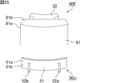
- FIG. 25 is a schematic perspective view showing the divided core and terminal plate in FIG. 24 in an exploded state.
- FIG. 26 is a schematic cross-sectional view showing an example of a cross section of the coil unit shown in FIG. 24 along line segment c1-c2.
- the coil unit 70J shown in FIG. 24 includes a split core 80F, a coil 40A, and a terminal plate 50J.
- the split core 80F of the coil unit 70J has the same configuration as the split core 80F of the coil unit 70F.
- the outer circumferential surface 81a of the split yoke 81 and the first surface 51a of the plate portion 51 are, for example, joined.
- the outer circumferential surface 81a of the split yoke 81 and the first surface 51a of the plate portion 51 may be fitted together at the outer circumferential side fitting portion, as in the coil unit 70A.
- the terminal portion 52a of the terminal plate 50J does not penetrate between the first surface 51a and the second surface 51b of the plate portion 51. That is, in the terminal board 50J, the terminal portion 52a is not exposed from the first surface 51a of the plate portion 51.
- This allows a structure in which the terminal portion 52a does not come into contact with the split yoke 81 while the terminal plate 50J is fixed to the outer peripheral surface 81a of the split yoke 81. Therefore, according to the structure shown in FIG. 26, insulation between the split yoke 81 and the terminal portion 52a is ensured. Furthermore, according to the structure shown in FIG.
- solder joint when using, for example, solder joint when electrically connecting one end 41a of the winding 41 and the terminal of the connection board as described later, solder joint is used.
- the heat generated at the time is less likely to be transmitted from the terminal portion 52a to the split yoke 81, and as a result, the split core 80F is less likely to be damaged, so the strength of the coil unit 70J (more specifically, the split core 80F) is reduced. suppressed.
- the terminal portion 52a does not penetrate between the first surface 51a and the second surface 51b of the plate portion 51
- the terminal portion 52b It does not have to penetrate between the surface 51b, or it may penetrate between the first surface 51a and the second surface 51b of the plate part 51.
- the terminal portion does not need to penetrate between the first surface and the second surface of the plate portion.
- the terminal portion may penetrate between the first surface and the second surface of the plate portion.
- the bottom portion of the terminal portion may have a shape that is wider than the portion other than the bottom portion in a direction perpendicular to the direction in which the terminal portion extends.
- the bottom portion of the terminal portion may be spaced apart from the outer circumferential surface of the yoke in the direction in which the terminal portion extends.
- FIG. 27 is a schematic perspective view showing a coil unit that constitutes an example of a stator according to Embodiment 8 of the present invention.
- FIG. 28 is a schematic perspective view showing the split core and terminal plate in FIG. 27 in an exploded state.
- FIG. 29 is a schematic cross-sectional view showing an example of a cross section of the coil unit shown in FIG. 27 along line segment d1-d2.
- the coil unit 70K shown in FIG. 27 includes a split core 80F, a coil 40A, and a terminal plate 50K.
- the split core 80F included in the coil unit 70K has the same configuration as the split core 80F included in the coil unit 70F.
- the outer peripheral surface 81a of the split yoke 81 and the first surface 51a of the plate portion 51 are, for example, joined.
- the outer circumferential surface 81a of the split yoke 81 and the first surface 51a of the plate portion 51 may be fitted together at the outer circumferential side fitting portion, as in the coil unit 70A.
- the terminal portion 52a penetrates between the first surface 51a and the second surface 51b of the plate portion 51. That is, in the terminal board 50K, the terminal portion 52a is exposed from the first surface 51a of the plate portion 51.
- the bottom of the terminal portion 52a is wider than the portion other than the bottom in the direction perpendicular to the direction in which the terminal portion 52a extends (in the axial direction in FIG. 29). It has a similar shape. Since the bottom of the terminal portion 52a has a widened shape as described above, the terminal portion 52a becomes difficult to come off from the plate portion 51.
- the bottom of the terminal portion 52a is separated from the outer circumferential surface 81a of the split yoke 81 in the direction in which the terminal portion 52a extends. That is, a cavity 88 is provided between the terminal portion 52a and the split yoke 81.
- the terminal part 50K is fixed to the outer peripheral surface 81a of the split yoke 81. It is possible to adopt a structure in which the portion 52a does not come into contact with the split yoke 81. Therefore, according to the structure shown in FIG.
- the split yoke 81 insulation between the split yoke 81 and the terminal portion 52a is ensured. Further, according to the structure shown in FIG. 29, when using, for example, solder joint to electrically connect one end 41a of the winding 41 and the terminal of the connection board as described later, the solder joint The heat generated at the time is less likely to be transmitted from the terminal portion 52a to the split yoke 81, and as a result, the split core 80F is less likely to be damaged, so the strength of the coil unit 70K (more specifically, the split core 80F) is reduced. suppressed.
- the terminal plate 50K having the structure shown in FIG. 29 can be manufactured, for example, by press-fitting the terminal portion 52a into the plate portion 51 from the first surface 51a side. According to such a manufacturing method, since the terminal portion 52a can be easily fixed to the plate portion 51, the manufacturing efficiency of the terminal board 50K can be easily improved.
- the terminal portion 52a and the terminal portion 52b penetrates between the first surface 51a and the second surface 51b of the plate portion 51, and the terminal portion 52a and the terminal Only one of the portions 52b may penetrate between the first surface 51a and the second surface 51b of the plate portion 51.
- the terminal portion 52b penetrates between the first surface 51a and the second surface 51b of the plate portion 51. It may penetrate between the surface 51b, or it does not need to penetrate between the first surface 51a and the second surface 51b of the plate portion 51.
- the bottom of the terminal portion 52b extends from the bottom of the terminal portion 52b, similarly to FIG. 29. It may have a shape that is wider than the portion other than the bottom in the direction orthogonal to the direction. Furthermore, similarly to FIG. 29, the bottom of the terminal portion 52b may be separated from the outer circumferential surface 81a of the split yoke 81 in the direction in which the terminal portion 52b extends.
- the terminal portion may also penetrate between the first surface and the second surface of the plate portion.
- the terminal board has two terminal parts, but in the stator of the present invention, the terminal board may have only one terminal part. That is, in the stator of the present invention, only one end of the winding may be fixed in a state where it is wrapped around the terminal portion.
- a stator that is different from the stator of Embodiment 4 of the present invention in this respect will be described below as a stator of Embodiment 9 of the present invention.
- FIG. 30 is a schematic perspective view showing an example of a stator according to Embodiment 9 of the present invention.
- FIG. 31 is a schematic perspective view showing the coil unit in FIG. 30.
- the stator 20L shown in FIG. 30 has a coil unit 70L.
- the coil unit 70L shown in FIG. 31 includes a split core 80F, a coil 40A, and a terminal plate 50L.
- the split core 80F included in the coil unit 70L has the same configuration as the split core 80F included in the coil unit 70F.
- the terminal board 50L has a plate portion 51 and a terminal portion 52a.
- One end 41a of the winding 41 is fixed and wound around the terminal 52a. Thereby, one end 41a of the winding 41 is led out to the terminal plate 50L.
- the coil unit 70L is used, for example, to connect the windings 41 of the plurality of coils 40A in series.
- the stator 20L may further include a coil unit 71L in which both ends of the winding 41 are not led out to the terminal plate. That is, in the stator 20L, the coil unit 70L has a structure in which one end 41a of the winding 41 is led out to the terminal plate, and the coil unit 71L has a structure in which both ends of the winding 41 are not led out to the terminal board. , may be mixed. In this case, since it is not necessary to provide a terminal board in every coil unit, the cost related to the terminal board can be reduced.
- the terminal board may have only one terminal portion.
- the stator core has a split structure divided into split cores, but in the stator of the present invention, the stator core may have an undivided integrated structure. .
- the coils 40A can be arranged more closely, and as a result, the number of coils 40A can be increased compared to a stator in which the stator core is an integrated structure. can. Therefore, with a stator having a split stator core structure, the characteristics of the motor can be improved more easily than with a stator having an integrated stator core structure.
- the stator of the present invention is not only used as a component of a motor, which will be described later, but may also be used, for example, as a component of a generator.
- the motor of the present invention is characterized by comprising the stator of the present invention and a rotor provided opposite to the inner circumferential surface of the stator.
- FIG. 32 is a schematic perspective view showing an example of a motor according to Embodiment 10 of the present invention.
- the motor 1A shown in FIG. 32 includes a rotor 10A and a stator 20A.
- the rotor 10A is located on the inner side of the same axis, and the stator 20A is located on the outer side of the same axis.
- the axis AX corresponds to the rotation axis of the rotor 10A.
- the rotor 10A is provided facing the inner peripheral surface of the stator 20A.
- the rotor 10A includes, for example, a rotor yoke 11, a shaft 12, and a permanent magnet 13.
- the rotor yoke 11 is composed of, for example, a bulk soft magnetic material, an electromagnetic steel plate, a dust core, a resin molded body containing a soft magnetic material, or the like.
- the shaft 12 is inserted through the rotor yoke 11.
- Examples of the constituent material of the shaft 12 include metals such as stainless steel.
- the direction in which the shaft 12 extends that is, the direction in which the axis AX extends is parallel to the axial direction.
- the permanent magnets 13 are provided so that north and south poles are alternately arranged along the outer peripheral surface of the rotor yoke 11.
- the rotor 10A When viewed from the axial direction, the rotor 10A may have a substantially circular shape or a substantially polygonal shape.
- a motor in which a plurality of coil units 70A are arranged in an annular manner in the circumferential direction, but the motor has a stator in which other coil units such as the coil unit 70B are arranged in an annular manner in the circumferential direction. The same applies to the motor.
- the motor of the present invention may further include a wiring board electrically connected to one end of the winding.
- the wiring board may be provided so as to face the terminal plate on the outer peripheral surface of the yoke.
- a motor that is different from the motor of Embodiment 10 of the present invention in this respect will be described below as a motor of Embodiment 11 of the present invention.
- FIG. 33 is a schematic perspective view showing an example of a motor according to Embodiment 11 of the present invention.
- the motor 1B shown in FIG. 33 further includes a wiring board 25A in addition to the rotor 10A and stator 20A.
- the wiring board 25A is electrically connected to one end 41a of the winding 41 of the coil 40A of the stator 20A. Furthermore, it is preferable that the wiring board 25A is electrically connected to the other end 41b of the winding 41 of the coil 40A of the stator 20A. An example of this connection mode will be described below.
- a plurality of through holes 26 passing through between one main surface and the other main surface are provided in the wiring board 25A so as to be spaced apart from each other in the circumferential direction.
- a terminal (not shown) is exposed on the inner wall surface of each through hole 26.
- the wiring board 25A is provided to face the terminal plate 50A on the outer peripheral surface 31a of the yoke 31. More specifically, the wiring board 25A is wound around the stator 20A in the circumferential direction so that the terminal portions 52a and 52b pass through separate through holes 26. On the other hand, one end 41a of the winding 41 is tied and fixed to the terminal part 52a, and the other end 41b of the winding 41 is tied and fixed to the terminal part 52b. There is.
- the motor 1B in which the wiring board 25A is wound around the stator 20A in the circumferential direction as described above one end 41a of the winding 41 wound around the terminal part 52a and the terminal part 52b It becomes possible to efficiently connect the other end portion 41b of the winding wire 41 wound therein to the terminal exposed from the inner wall surface of the separate through hole 26. Furthermore, in the motor 1B, since the wiring board 25A is provided to face the terminal plate 50A on the outer peripheral surface 31a of the yoke 31, the thickness of the motor 1B increases, and more specifically, the shaft of the motor 1B increases. The increase in dimension in the direction is suppressed.
- the one end 41a of the winding 41 can be electrically connected to the terminal of the wiring board 25A, and the other end 41b of the winding 41 can be electrically connected while suppressing the increase in thickness. Electrical connection with the terminals of the substrate 25A can be easily realized.
- the wiring board 25A is used while being wound around the stator 20A in the circumferential direction, it is preferably a board with excellent flexibility, such as a flexible printed circuit board (FPC).
- FPC flexible printed circuit board
- a stator core comprising an annular yoke extending in a circumferential direction and teeth protruding from an inner circumferential surface of the yoke in a radial direction of the yoke, and made of a molded body of magnetic powder; A coil made up of a winding wire wound around the teeth; a terminal plate provided on the outer peripheral surface of the yoke in the radial direction, The terminal board has a plate portion and a terminal portion fixed to the plate portion, The plate portion has a first surface located on the outer peripheral surface side of the yoke in the radial direction, and a second surface located on the opposite side to the outer peripheral surface of the yoke, The terminal portion protrudes from at least the second surface of the plate portion, A stator characterized in that one end of the winding is fixed to the terminal in a wound state.
- the outer circumferential surface side mating portion includes a convex portion protruding from one of the outer circumferential surface of the yoke and the first surface of the plate portion, and the other of the outer circumferential surface of the yoke and the first surface of the plate portion.
- the convex portion is provided so as to protrude from the first surface of the plate portion in a direction in which the terminal portion extends,
- the plate portion includes a first plate portion facing the outer peripheral surface of the yoke, and a second plate portion extending from a part of the first plate portion so as to face an end surface of the yoke in the axial direction of the stator core.
- the first plate portion has the first surface and the second surface, Any one of ⁇ 1> to ⁇ 5>, wherein the second plate portion has a third surface located on the end surface side of the yoke, and a fourth surface located on the opposite side to the end surface of the yoke. stator as described in .
- the end surface side mating portion includes a convex portion protruding from one of the end surface of the yoke and the third surface of the second plate portion, and a convex portion protruding from one of the end surface of the yoke and the third surface of the second plate portion.
- the end surface of the yoke is provided with a yoke groove extending in the direction in which the second plate portion extends;
- the fourth surface of the second plate portion is provided with a guide groove along the direction in which the second plate portion extends,
- the stator according to any one of ⁇ 6> to ⁇ 9>, wherein the winding extends toward the terminal portion so as to pass through the guide groove on one end side.
- the outer circumferential surface of the yoke includes a first outer circumferential surface, a second outer circumferential surface located inside the first outer circumferential surface in the radial direction, and a step connecting the first outer circumferential surface and the second outer circumferential surface. having a surface;
- the stator according to any one of ⁇ 1> to ⁇ 11>, wherein the terminal plate is provided on the stepped surface.
- the outer peripheral surface of the yoke is provided with a recess that overlaps the terminal portion in the direction in which the terminal portion extends,
- the stator according to any one of ⁇ 1> to ⁇ 12>, wherein the terminal portion is spaced apart from the bottom surface of the recess in the direction in which the terminal portion extends.
- ⁇ 14> The stator according to any one of ⁇ 1> to ⁇ 13>, wherein the terminal portion does not penetrate between the first surface and the second surface of the plate portion.
- ⁇ 15> The stator according to any one of ⁇ 1> to ⁇ 13>, wherein the terminal portion penetrates between the first surface and the second surface of the plate portion.
- ⁇ 18> The stator according to any one of ⁇ 1> to ⁇ 17>, wherein the terminal plate is provided along a boundary between the outer peripheral surface of the yoke and an end surface of the yoke in the axial direction of the stator core.
- a plurality of coil units are arranged in a ring shape in the circumferential direction, The plurality of coil units each independently include a divided core formed by dividing the stator core in the circumferential direction, the coil, and the terminal plate, according to ⁇ 1> to ⁇ 18>.
- stator according to any one of ⁇ 1> to ⁇ 19>, wherein the stator core is composed of a powder magnetic core.
- ⁇ 21> The stator according to any one of ⁇ 1> to ⁇ 20>, wherein the terminal portion is made of a conductive material.
- a motor comprising: a rotor provided opposite to the inner circumferential surface of the stator.
- ⁇ 23> The motor according to ⁇ 22>, further comprising a wiring board electrically connected to one end of the winding.
Landscapes
- Engineering & Computer Science (AREA)
- Power Engineering (AREA)
- Iron Core Of Rotating Electric Machines (AREA)
- Insulation, Fastening Of Motor, Generator Windings (AREA)
Priority Applications (1)
| Application Number | Priority Date | Filing Date | Title |
|---|---|---|---|
| JP2024539100A JPWO2024029420A1 (https=) | 2022-08-03 | 2023-07-26 |
Applications Claiming Priority (2)
| Application Number | Priority Date | Filing Date | Title |
|---|---|---|---|
| JP2022123939 | 2022-08-03 | ||
| JP2022-123939 | 2022-08-03 |
Publications (1)
| Publication Number | Publication Date |
|---|---|
| WO2024029420A1 true WO2024029420A1 (ja) | 2024-02-08 |
Family
ID=89848972
Family Applications (1)
| Application Number | Title | Priority Date | Filing Date |
|---|---|---|---|
| PCT/JP2023/027355 Ceased WO2024029420A1 (ja) | 2022-08-03 | 2023-07-26 | ステータ及びモータ |
Country Status (2)
| Country | Link |
|---|---|
| JP (1) | JPWO2024029420A1 (https=) |
| WO (1) | WO2024029420A1 (https=) |
Citations (2)
| Publication number | Priority date | Publication date | Assignee | Title |
|---|---|---|---|---|
| JP2005328621A (ja) * | 2004-05-13 | 2005-11-24 | Nidec Copal Corp | ステッピングモータ |
| JP2010279205A (ja) * | 2009-05-29 | 2010-12-09 | Nissan Motor Co Ltd | スイッチング素子一体型回転電機 |
-
2023
- 2023-07-26 JP JP2024539100A patent/JPWO2024029420A1/ja active Pending
- 2023-07-26 WO PCT/JP2023/027355 patent/WO2024029420A1/ja not_active Ceased
Patent Citations (2)
| Publication number | Priority date | Publication date | Assignee | Title |
|---|---|---|---|---|
| JP2005328621A (ja) * | 2004-05-13 | 2005-11-24 | Nidec Copal Corp | ステッピングモータ |
| JP2010279205A (ja) * | 2009-05-29 | 2010-12-09 | Nissan Motor Co Ltd | スイッチング素子一体型回転電機 |
Also Published As
| Publication number | Publication date |
|---|---|
| JPWO2024029420A1 (https=) | 2024-02-08 |
Similar Documents
| Publication | Publication Date | Title |
|---|---|---|
| CN100428612C (zh) | 用于电机定子的互连环和线导向件 | |
| CN101171733B (zh) | 电动机、旋转电机及其定子、以及该定子的制造方法 | |
| JP5533285B2 (ja) | 絶縁部材、ステータの製造方法 | |
| WO2017159858A1 (ja) | 電動機用ロータ、およびブラシレスモータ | |
| JPWO2020017133A1 (ja) | 分布巻ラジアルギャップ型回転電機及びその固定子 | |
| US7893590B2 (en) | Stator having high assembly | |
| WO2017199736A1 (ja) | バスバーユニット及び回転電機 | |
| CN101416369A (zh) | 旋转电机用末端组件以及旋转电机 | |
| CN112640259A (zh) | 马达及马达的制造方法 | |
| WO2018150964A1 (ja) | モータおよびポンプ装置 | |
| US12095322B2 (en) | Stator | |
| CN113491052B (zh) | 定子和马达 | |
| JP6498536B2 (ja) | コアおよび回転電機 | |
| JP7691374B2 (ja) | バスバーユニット | |
| JP2010011569A (ja) | ステータ | |
| JP2019030143A (ja) | コネクタ及びコネクタを備えたモータ | |
| WO2024029420A1 (ja) | ステータ及びモータ | |
| CN106411014A (zh) | 旋转电机及其制造方法、定子线圈、线圈树脂结构体 | |
| CN211930351U (zh) | 定子以及无刷马达 | |
| JP7845468B2 (ja) | ステータ及びモータ | |
| JP2020010539A (ja) | ロータ、及びブラシレスモータ | |
| CN110462978A (zh) | 电动马达用定子和电动马达 | |
| JP2023054419A (ja) | 回転電機 | |
| US20250293561A1 (en) | Stator and method for producing stator | |
| WO2024154569A1 (ja) | ステータ及びモータ |
Legal Events
| Date | Code | Title | Description |
|---|---|---|---|
| 121 | Ep: the epo has been informed by wipo that ep was designated in this application |
Ref document number: 23849975 Country of ref document: EP Kind code of ref document: A1 |
|
| WWE | Wipo information: entry into national phase |
Ref document number: 2024539100 Country of ref document: JP |
|
| NENP | Non-entry into the national phase |
Ref country code: DE |
|
| 122 | Ep: pct application non-entry in european phase |
Ref document number: 23849975 Country of ref document: EP Kind code of ref document: A1 |