WO2024029065A1 - 電動機、およびコアの製造方法 - Google Patents
電動機、およびコアの製造方法 Download PDFInfo
- Publication number
- WO2024029065A1 WO2024029065A1 PCT/JP2022/030076 JP2022030076W WO2024029065A1 WO 2024029065 A1 WO2024029065 A1 WO 2024029065A1 JP 2022030076 W JP2022030076 W JP 2022030076W WO 2024029065 A1 WO2024029065 A1 WO 2024029065A1
- Authority
- WO
- WIPO (PCT)
- Prior art keywords
- core
- edge
- groove
- electric motor
- protrusion
- Prior art date
- Legal status (The legal status is an assumption and is not a legal conclusion. Google has not performed a legal analysis and makes no representation as to the accuracy of the status listed.)
- Ceased
Links
Images







Classifications
-
- H—ELECTRICITY
- H02—GENERATION; CONVERSION OR DISTRIBUTION OF ELECTRIC POWER
- H02K—DYNAMO-ELECTRIC MACHINES
- H02K1/00—Details of the magnetic circuit
- H02K1/06—Details of the magnetic circuit characterised by the shape, form or construction
-
- H—ELECTRICITY
- H02—GENERATION; CONVERSION OR DISTRIBUTION OF ELECTRIC POWER
- H02K—DYNAMO-ELECTRIC MACHINES
- H02K15/00—Processes or apparatus specially adapted for manufacturing, assembling, maintaining or repairing of dynamo-electric machines
- H02K15/02—Processes or apparatus specially adapted for manufacturing, assembling, maintaining or repairing of dynamo-electric machines of stator or rotor bodies
Definitions
- the present disclosure relates to an electric motor and a method for manufacturing a core.
- Patent Document 1 It is known that the core of an electric motor is formed from a steel plate (for example, Patent Document 1).
- protrusions may be formed on the edges of the steel plate. If a protrusion is formed on the edge, the protrusion will catch on other parts, making it impossible to assemble the core with high precision.
- An electric motor using a ring-shaped core the core has grooves at regular intervals on the edge, and protrusions formed by machining are arranged in the grooves.
- a manufacturing method for manufacturing a ring-shaped core which includes a process of forming an edge having a groove in a steel plate, and a protrusion formed by the process is arranged in the groove.
- an electric motor can be assembled with high precision and manufactured at low cost.
- FIG. 3 is a plan view showing an example of a core. 2 is a partially enlarged view of the core of FIG. 1.
- FIG. It is a figure explaining notching press processing. It is a figure which shows an example of the metal mold
- FIG. 3 is a plan view showing an example of a stator core. 10 is a partially enlarged view of the core of FIG. 9. FIG. It is a figure showing an example of a stator attached to a jacket.
- the core is a component that constitutes the electric motor, and is a component that serves as a path for magnetic flux.
- the core includes a rotor core and a stator core.
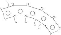
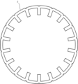
- FIG. 1 is a plan view showing an example of the core.
- Core 1 shown in FIG. 1 is a rotor core.
- the core 1 is a ring-shaped plate material.
- the core 1 is manufactured by processing an electromagnetic steel plate into a predetermined ring shape.
- FIG. 2 is a partially enlarged view of the core 1 in FIG. 1.
- the core 1 is provided with grooves 12 at regular intervals on the edge 11.
- the edge 11 is located on the outer periphery or inner periphery of the ring-shaped core 1.
- the groove 12 is a recess formed from the outer periphery toward the inner side of the core 1 or a recess formed from the inner periphery toward the outer side of the core 1 .
- a protrusion 13 formed by machining is arranged in the groove portion 12 .
- the depth of the groove portion 12 is formed deeper than the height of the protrusion 13.
- the depth of the groove 12 is the distance from the inner circumference to the bottom of the groove 12. In other words, the depth of the groove 12 is the distance in the radial direction of the core 1 from the bottom of the groove 12 to the inner circumference.
- the depth of the groove portion 12 is, for example, 0.3 [mm] or more.
- the core 1 is formed by, for example, notching press processing.
- the core 1 is manufactured by repeatedly punching out a portion of the core 1 using a press machine using a die.
- the portion 14 where the edge portion 11 and the groove portion 12 are in contact may be formed in an arc shape.
- the boundary portion between the edge portion 11 and the groove portion 12 may be rounded.
- FIG. 3 is a diagram illustrating notching press processing.
- a press machine punches out a portion of the core 1 with one press operation, rotates the core 1 by a predetermined angle, and performs the next punching.
- the core 1 is rotated by ⁇ °, and the next press operation is performed.
- the press machine repeatedly performs such operations to process the core 1 into a predetermined shape.
- a protrusion 13 is formed at the boundary between a portion of the core 1 formed by one press operation and a portion of the core 1 formed by the next press operation.
- the protrusion 13 is a burr. That is, this protrusion 13 is made of the same material as the electromagnetic steel plate that makes up the core 1.
- the height of the protrusion 13 is, for example, 0.1 [mm] or less.
- the processing is performed so that the protrusions 13 are arranged in the grooves 12.
- the press machine performs notching press processing using a mold having a shape in which the projections 13 are arranged in the grooves 12.
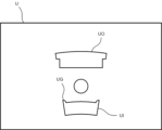
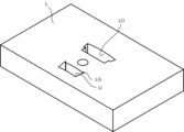
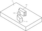
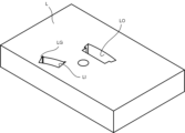
- FIGS. 4A to 4C are diagrams showing an example of a mold used for notching press processing. Specifically, FIG. 4A is a plan view of the upper mold. FIG. 4B is a perspective view of the upper die. FIG. 4C is a perspective view of the lower mold.
- the upper die is equipped with a convex portion for forming the electromagnetic steel sheet into a predetermined shape.
- the convex portion includes an outer periphery forming part UO for forming the outer periphery of the core 1 and an inner periphery forming part UI for forming the inner periphery of the core 1. Further, the convex portion includes a groove forming portion UG for forming the groove portion 12 of the core 1.
- the lower die is equipped with a recess for forming the electromagnetic steel sheet into a predetermined shape.
- the recess includes an outer periphery forming part LO for forming the outer periphery of the core 1 and an inner periphery forming part LI for forming the inner periphery of the core 1.
- the recessed portion includes a groove forming portion LG for forming the groove portion 12 of the core 1.
- the convex part of the upper mold is forcefully inserted into the recess of the lower mold with the electromagnetic steel plate placed between the upper mold and the lower mold.
- a hole having the same shape as the convex portion and the concave portion or the same external shape as a part of the convex portion and the concave portion is formed in the electromagnetic steel sheet.
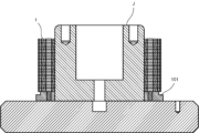
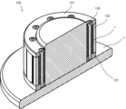
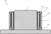
- FIGS. 5A and 5B and FIGS. 6A to 6C are diagrams for explaining the process of assembling a rotor using the core 1.
- 7A to 7C are views showing an example of the rotor 100 removed from the guide jig J.
- the rotor plate 101 is attached to the guide jig J (see FIGS. 5A and 5B).
- a plurality of cores 1 are attached to the guide jig J (see FIGS. 5A and 5B).
- a predetermined number of cores 1 are stacked with their inner peripheries guided by the outer periphery of the guide jig J.
- the core 1 cannot be assembled with high precision.
- the core 1 of this embodiment since the protrusion 13 is arranged in the groove 12, the protrusion 13 will not be caught on the outer peripheral portion of the guide jig J. Therefore, the core 1 can be assembled with high precision.
- another rotor plate 101 is attached to the guide jig J. That is, multiple cores 1 and multiple magnets 102 are sandwiched between two rotor plates 101. Next, the two rotor plates 101 are fixed with bolts 103. Next, a magnet 102 is attached to the outer periphery of the core 1 (see FIGS. 6A to 6C). Finally, the rotor 100 is removed from the guide jig J (see FIGS. 7A to 7C).
- the core 1 is smoother than when the boundary between the edge 11 and the groove 12 has a corner. It can be inserted into the guide jig J.
- the edge 11 may be in contact with the shaft.
- shafts may be shrink-fitted to the plurality of cores 1 after the plurality of cores 1 are assembled.
- the edge 11 will be in direct contact with the shaft. That is, in the core 1 of this embodiment, since the protrusion 13 is arranged in the groove portion 12, the protrusion 13 and the shaft do not come into contact with each other. Therefore, the core 1 and the shaft can be assembled with high precision.
- molds used for notching press processing are not limited to those shown in FIGS. 4A to 4C.
- FIGS. 8A to 8C are diagrams showing other examples of molds used for notching press processing. Specifically, FIG. 8A is a plan view of the upper mold. FIG. 8B is a perspective view of the upper die. FIG. 8C is a perspective view of the lower mold.
- the upper mold shown in FIGS. 8A and 8B includes an outer periphery forming part UO that forms the outer periphery of the core 1 and an inner periphery forming part UI that forms the inner periphery of the core 1.
- the lower die shown in FIG. 8C includes an outer circumference forming part LO for forming the outer circumference of the core 1 and an inner circumference forming part LI for forming the inner circumference of the core 1.
- the outer periphery forming part UO and the inner periphery forming part UI of the upper mold are formed out of phase with each other.
- the outer periphery forming part LO and the inner periphery forming part LI of the lower mold are formed out of phase with each other.
- the rotor core was described, but the core 1 may be a stator core.
- FIG. 9 is a plan view showing an example of the stator core.
- the core 2 is a ring-shaped plate material.
- the core 2 is manufactured, for example, by processing an electromagnetic steel plate into a predetermined shape.
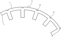
- FIG. 10 is a partially enlarged view of the core 2 in FIG. 9.
- the core 2 is provided with grooves 22 on the edge 21 at regular intervals.
- the edge 21 is located at the outer periphery of the core 2.
- a protrusion 23 formed by machining is arranged in the groove portion 22 .
- the edge 21 When the edge 21 is located on the outer periphery of the core 2, the edge 21 may be in contact with the jacket.
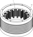
- FIG. 11 is a diagram showing an example of a stator core attached to a jacket.
- the jacket 201 is a component for cooling the electric motor.
- the jacket 201 and the core 2 are assembled by shrink-fitting or using an anaerobic adhesive so that no gaps are provided.
- a groove 22 is formed in the edge 21 of the core 2 of this embodiment, and a protrusion 23 is arranged in the groove 22. Therefore, the core 2 and the jacket 201 can be assembled with high accuracy without the protrusion 23 coming into contact with the jacket 201.
- the core 2 is not limited to notching press processing, and may be processed using a laser.
- protrusions 23 are likely to be formed at the processing start point and the processing end point where laser irradiation is started. Therefore, by arranging the processing start point and the processing end point within the groove 22, the protrusion 23 can be arranged in the groove 22.
- the protrusion 23 is a burr.
- protrusions 23 may occur at positions where the direction of processing changes.
- the position where the direction of processing changes is the position where the moving direction of the processing head of the laser beam machine changes from the plus direction of the control axis to the minus direction, or from the minus direction to the plus direction.
- This protrusion 23 is formed due to, for example, changes in the acceleration of the control axis of the laser processing machine, backlash of the ball screw, and the like.
- This projection 23 is called a quadrant projection.
- the protrusion 23 is formed on the outer periphery of the stator core of the core 2, the protrusion 23 and the jacket 201 may get caught and it may not be possible to assemble the two accurately.
- the core 2 of this embodiment includes a groove 22 in the edge 21 where the quadrant protrusion is formed, and a protrusion 23 is arranged in the groove 22. This can prevent the protrusion 23 and the jacket 201 from getting caught.
Landscapes
- Engineering & Computer Science (AREA)
- Power Engineering (AREA)
- Manufacturing & Machinery (AREA)
- Iron Core Of Rotating Electric Machines (AREA)
- Manufacture Of Motors, Generators (AREA)
Abstract
Description
11 縁部
12 溝部
13 突起
14 縁部と溝部とが接する部分
101 ロータプレート
102 磁石
103 ボルト
2 コア
21 縁部
22 溝部
23 突起
201 ジャケット
J ガイド治具
Claims (5)
- リング状のコアを用いた電動機であって、
前記コアは縁部に一定の間隔で溝部を備え、
前記溝部には、加工によって形成される突起が配置される前記コアを用いた電動機。 - 前記縁部と前記溝部とが接する部分は円弧形状に形成される請求項1に記載の電動機。
- 前記縁部は内周に位置し、前記縁部はシャフトに接する請求項1または2に記載の電動機。
- 前記縁部は外周に位置し、前記縁部はジャケットに接する請求項1または2に記載の電動機。
- リング状のコアを製造する製造方法であって、
溝部を有する縁部を鋼板に形成する加工を含み、
前記溝部には、前記加工によって形成される突起が配置されるコアの製造方法。
Priority Applications (4)
| Application Number | Priority Date | Filing Date | Title |
|---|---|---|---|
| JP2024538784A JPWO2024029065A1 (ja) | 2022-08-05 | 2022-08-05 | |
| PCT/JP2022/030076 WO2024029065A1 (ja) | 2022-08-05 | 2022-08-05 | 電動機、およびコアの製造方法 |
| DE112022007242.3T DE112022007242T5 (de) | 2022-08-05 | 2022-08-05 | Elektromotor und verfahren zum herstellen eines kerns |
| CN202280098479.XA CN119585977A (zh) | 2022-08-05 | 2022-08-05 | 电动机以及铁芯的制造方法 |
Applications Claiming Priority (1)
| Application Number | Priority Date | Filing Date | Title |
|---|---|---|---|
| PCT/JP2022/030076 WO2024029065A1 (ja) | 2022-08-05 | 2022-08-05 | 電動機、およびコアの製造方法 |
Publications (1)
| Publication Number | Publication Date |
|---|---|
| WO2024029065A1 true WO2024029065A1 (ja) | 2024-02-08 |
Family
ID=89848750
Family Applications (1)
| Application Number | Title | Priority Date | Filing Date |
|---|---|---|---|
| PCT/JP2022/030076 Ceased WO2024029065A1 (ja) | 2022-08-05 | 2022-08-05 | 電動機、およびコアの製造方法 |
Country Status (4)
| Country | Link |
|---|---|
| JP (1) | JPWO2024029065A1 (ja) |
| CN (1) | CN119585977A (ja) |
| DE (1) | DE112022007242T5 (ja) |
| WO (1) | WO2024029065A1 (ja) |
Citations (2)
| Publication number | Priority date | Publication date | Assignee | Title |
|---|---|---|---|---|
| JPH0880013A (ja) * | 1994-09-05 | 1996-03-22 | Mitsubishi Electric Corp | 突起部を有した鉄心板からなる鉄心およびその製造方法とその鉄心板のプレス抜き型とその鉄心板の製造装置およびその鉄心板の製造方法 |
| US20110016701A1 (en) * | 2009-07-21 | 2011-01-27 | Mark Bender | Production method for large rotor/stator laminations |
-
2022
- 2022-08-05 JP JP2024538784A patent/JPWO2024029065A1/ja active Pending
- 2022-08-05 DE DE112022007242.3T patent/DE112022007242T5/de active Pending
- 2022-08-05 CN CN202280098479.XA patent/CN119585977A/zh active Pending
- 2022-08-05 WO PCT/JP2022/030076 patent/WO2024029065A1/ja not_active Ceased
Patent Citations (2)
| Publication number | Priority date | Publication date | Assignee | Title |
|---|---|---|---|---|
| JPH0880013A (ja) * | 1994-09-05 | 1996-03-22 | Mitsubishi Electric Corp | 突起部を有した鉄心板からなる鉄心およびその製造方法とその鉄心板のプレス抜き型とその鉄心板の製造装置およびその鉄心板の製造方法 |
| US20110016701A1 (en) * | 2009-07-21 | 2011-01-27 | Mark Bender | Production method for large rotor/stator laminations |
Also Published As
| Publication number | Publication date |
|---|---|
| JPWO2024029065A1 (ja) | 2024-02-08 |
| DE112022007242T5 (de) | 2025-03-27 |
| CN119585977A (zh) | 2025-03-07 |
Similar Documents
| Publication | Publication Date | Title |
|---|---|---|
| US10985637B2 (en) | Laminated core manufacturing method | |
| WO2011125199A1 (ja) | 回転電機の積層鉄心 | |
| WO2009093524A1 (ja) | 回転子積層鉄心 | |
| US5539974A (en) | Method for producing laminated iron cores | |
| US11309776B2 (en) | Manufacturing method of core for rotary electric machine | |
| EP3474427B1 (en) | Manufacturing method of core of rotating electrical machine, and core of rotating electrical machine | |
| WO2024029065A1 (ja) | 電動機、およびコアの製造方法 | |
| CN114079332A (zh) | 定子芯部和电动机 | |
| CN111758208B (zh) | 转子铁芯部件制造方法以及转子铁芯部件 | |
| JP2007228720A (ja) | コア | |
| CN115694099A (zh) | 转子铁芯制造方法及转子铁芯制造装置 | |
| WO2022239829A1 (ja) | 回転子及び回転電機並びに回転電機の製造方法 | |
| JP7599304B2 (ja) | 鋼板打抜き金型および回転電機の製造方法 | |
| JP2017175774A (ja) | 回転電機、および分割ステータ鋼板の製造方法 | |
| CN113631293B (zh) | 定子芯体板制造方法、定子芯体板、定子芯体以及模具 | |
| JP2014079059A (ja) | モータのステータ、およびその製造方法 | |
| JP4648716B2 (ja) | 積層鉄心とその製造方法 | |
| JP7633292B2 (ja) | モータのコアブロック及びモータのコアブロックの製造方法 | |
| JP2015149894A (ja) | 積層鉄心の製造方法およびそれにより製造された積層鉄心 | |
| JP7357811B2 (ja) | 分割コア、回転電機、分割コアの製造方法、および、回転電機の製造方法 | |
| WO2022209252A1 (ja) | Ipmモータ用ロータの製造方法及びipmモータ用ロータ | |
| CN111033982A (zh) | 定子铁芯制造方法 | |
| WO2019159847A1 (ja) | コア部材製造方法及びコア部材 | |
| JP2024058697A (ja) | ロータコア | |
| JP2018125986A (ja) | 回転電機のステータ |
Legal Events
| Date | Code | Title | Description |
|---|---|---|---|
| 121 | Ep: the epo has been informed by wipo that ep was designated in this application |
Ref document number: 22954053 Country of ref document: EP Kind code of ref document: A1 |
|
| WWE | Wipo information: entry into national phase |
Ref document number: 2024538784 Country of ref document: JP |
|
| WWE | Wipo information: entry into national phase |
Ref document number: 112022007242 Country of ref document: DE |
|
| WWE | Wipo information: entry into national phase |
Ref document number: 202280098479.X Country of ref document: CN |
|
| WWP | Wipo information: published in national office |
Ref document number: 202280098479.X Country of ref document: CN |
|
| WWP | Wipo information: published in national office |
Ref document number: 112022007242 Country of ref document: DE |
|
| 122 | Ep: pct application non-entry in european phase |
Ref document number: 22954053 Country of ref document: EP Kind code of ref document: A1 |