WO2024028622A1 - 二次電池 - Google Patents
二次電池 Download PDFInfo
- Publication number
- WO2024028622A1 WO2024028622A1 PCT/IB2022/000434 IB2022000434W WO2024028622A1 WO 2024028622 A1 WO2024028622 A1 WO 2024028622A1 IB 2022000434 W IB2022000434 W IB 2022000434W WO 2024028622 A1 WO2024028622 A1 WO 2024028622A1
- Authority
- WO
- WIPO (PCT)
- Prior art keywords
- solid electrolyte
- electrolyte layer
- active material
- electrode active
- layer
- Prior art date
- Legal status (The legal status is an assumption and is not a legal conclusion. Google has not performed a legal analysis and makes no representation as to the accuracy of the status listed.)
- Ceased
Links
Images


Classifications
-
- H—ELECTRICITY
- H01—ELECTRIC ELEMENTS
- H01M—PROCESSES OR MEANS, e.g. BATTERIES, FOR THE DIRECT CONVERSION OF CHEMICAL ENERGY INTO ELECTRICAL ENERGY
- H01M10/00—Secondary cells; Manufacture thereof
- H01M10/05—Accumulators with non-aqueous electrolyte
- H01M10/052—Li-accumulators
-
- H—ELECTRICITY
- H01—ELECTRIC ELEMENTS
- H01M—PROCESSES OR MEANS, e.g. BATTERIES, FOR THE DIRECT CONVERSION OF CHEMICAL ENERGY INTO ELECTRICAL ENERGY
- H01M10/00—Secondary cells; Manufacture thereof
- H01M10/05—Accumulators with non-aqueous electrolyte
- H01M10/056—Accumulators with non-aqueous electrolyte characterised by the materials used as electrolytes, e.g. mixed inorganic/organic electrolytes
- H01M10/0561—Accumulators with non-aqueous electrolyte characterised by the materials used as electrolytes, e.g. mixed inorganic/organic electrolytes the electrolyte being constituted of inorganic materials only
- H01M10/0562—Solid materials
-
- H—ELECTRICITY
- H01—ELECTRIC ELEMENTS
- H01M—PROCESSES OR MEANS, e.g. BATTERIES, FOR THE DIRECT CONVERSION OF CHEMICAL ENERGY INTO ELECTRICAL ENERGY
- H01M10/00—Secondary cells; Manufacture thereof
- H01M10/05—Accumulators with non-aqueous electrolyte
- H01M10/058—Construction or manufacture
- H01M10/0585—Construction or manufacture of accumulators having only flat construction elements, i.e. flat positive electrodes, flat negative electrodes and flat separators
Definitions
- the present invention relates to a secondary battery using a solid electrolyte.
- Secondary batteries for motor drives are required to have extremely high output characteristics and high energy density compared to consumer secondary batteries used in mobile phones, notebook computers, etc. Therefore, lithium secondary batteries, which have the highest theoretical energy of all practical batteries, are attracting attention and are currently being rapidly developed.
- lithium secondary batteries that are currently in widespread use use a flammable organic electrolyte as the electrolyte.
- Such liquid-based lithium secondary batteries require more stringent safety measures against leakage, short circuits, overcharging, etc. than other batteries.
- a solid electrolyte is a material mainly composed of an ion conductor capable of ion conduction in a solid state. Therefore, in principle, all-solid-state lithium secondary batteries do not suffer from various problems caused by flammable organic electrolytes, unlike conventional liquid-based lithium secondary batteries. Furthermore, in general, the use of a high potential/large capacity positive electrode material and a large capacity negative electrode material can significantly improve the output density and energy density of the battery.
- an object of the present invention is to provide a means for improving the charging capacity during rapid charging in a secondary battery equipped with a solid electrolyte layer.
- the present inventors conducted extensive studies to solve the above problems. As a result, in a secondary battery using a solid electrolyte, two solid electrolyte layers are provided, and the thickness of the first solid electrolyte layer located on the positive electrode side is greater than the thickness of the second solid electrolyte layer located on the negative electrode side. It has been discovered that the above problem can be solved by reducing the binder concentration in the first solid electrolyte layer and making the binder concentration in the first solid electrolyte layer higher than that in the second solid electrolyte layer within a specific range, and has developed the present invention. I ended up completing it.
- one form of the present invention includes a positive electrode in which a positive electrode active material layer is disposed on the surface of a positive electrode current collector, a negative electrode in which a negative electrode active material layer is disposed on the surface of the negative electrode current collector, a solid electrolyte, and a binder.
- the present invention relates to a secondary battery including a first solid electrolyte layer and a second solid electrolyte layer, each of which contains a first solid electrolyte layer and a second solid electrolyte layer.
- the positive electrode and the negative electrode are arranged to face each other such that the positive electrode active material layer and the negative electrode active material layer sandwich the first solid electrolyte layer and the second solid electrolyte layer, and the first solid electrolyte layer
- the second solid electrolyte layer is disposed on the positive electrode active material layer side and the second solid electrolyte layer is disposed on the negative electrode active material layer side, the thickness of the first solid electrolyte layer is smaller than the thickness of the second solid electrolyte layer, and the first solid electrolyte layer is disposed on the positive electrode active material layer side.
- the ratio (A/B) of the concentration (A) [mass%] of the binder to the total solid content of the electrolyte layer and the concentration (B) [mass%] of the binder to the total solid content of the second solid electrolyte layer is It is characterized in that 1 ⁇ A/B ⁇ 4.5.
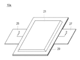
- FIG. 1 is a perspective view showing the appearance of a flat stacked secondary battery that is an embodiment of the present invention.
- FIG. 2 is a sectional view taken along line 2-2 shown in FIG.
- FIG. 3 is a schematic diagram showing an enlarged cross section of a single cell layer constituting a power generation element of the stacked secondary battery shown in FIGS. 1 and 2.
- FIG. 1 is a perspective view showing the appearance of a flat stacked secondary battery that is an embodiment of the present invention.
- FIG. 2 is a sectional view taken along line 2-2 shown in FIG.
- FIG. 3 is a schematic diagram showing an enlarged cross section of a single cell layer constituting a power generation element of the stacked secondary battery shown in FIGS. 1 and 2.
- FIG. 1 is a perspective view showing the appearance of a flat stacked secondary battery that is an embodiment of the present invention.
- FIG. 2 is a sectional view taken along line 2-2 shown in FIG.
- FIG. 3 is a schematic diagram showing an enlarged cross section of a single
- One form of the present invention includes a positive electrode in which a positive electrode active material layer is disposed on the surface of a positive electrode current collector, a negative electrode in which a negative electrode active material layer is disposed on the surface of the negative electrode current collector, a solid electrolyte, and a binder.
- first solid electrolyte layer and a second solid electrolyte layer each of which contains a first solid electrolyte layer and a second solid electrolyte layer;
- the first solid electrolyte layer is placed on the positive electrode active material layer side
- the second solid electrolyte layer is placed on the negative electrode active material layer side
- the thickness of the first solid electrolyte layer is is smaller than the thickness of the second solid electrolyte layer, and the concentration (A) [mass%] of the binder with respect to the total solid content of the first solid electrolyte layer and the concentration of the binder with respect to the total solid content of the second solid electrolyte layer
- B A secondary battery in which the ratio (A/B) of [mass%] is 1 ⁇ A/B ⁇ 4.5. According to this embodiment, the charging capacity during rapid charging can be improved in a secondary battery including a solid electrolyte layer.
- All-solid-state lithium secondary batteries have the advantage that, unlike conventional liquid-based lithium secondary batteries, problems caused by flammable organic electrolytes do not occur in principle. There is also the advantage that the output density and energy density of the battery can be significantly improved by using a negative electrode material with a large capacity.
- FIG. 1 is a perspective view showing the appearance of a flat stacked all-solid-state lithium secondary battery that is an embodiment of the present invention.
- FIG. 2 is a sectional view taken along line 2-2 shown in FIG.
- a flat stacked non-bipolar all-solid-state lithium secondary battery shown in FIGS. 1 and 2 will be used as an example for detailed explanation. do.
- both non-bipolar (internal parallel connection type) batteries and bipolar (internal series connection type) batteries is applicable.
- the stacked secondary battery 10a has a flat rectangular shape, and a negative current collector plate 25 and a positive current collector plate 27 for extracting power are pulled out from both sides of the battery. It is.
- the power generation element 21 is surrounded by the battery exterior material (laminate film 29) of the stacked secondary battery 10a, and the periphery thereof is heat-sealed. It is sealed in a state where it is pulled out to the outside.
- the power generation element 21 has a structure in which a positive electrode, a solid electrolyte layer 17, and a negative electrode are stacked.
- the positive electrode has a structure in which positive electrode active material layers 15 containing a positive electrode active material are disposed on both sides of a positive electrode current collector 11''.
- the negative electrode has a structure in which positive electrode active material layers 15 containing a positive electrode active material are arranged on both sides of a negative electrode current collector 11'. It has a structure in which an active material layer 13 is arranged.
- the solid electrolyte layer 17 is composed of two layers, a first solid electrolyte layer and a second solid electrolyte layer, as described later.
- a negative current collector plate 25 and a positive current collector plate 27 that are electrically connected to each electrode are attached to the negative electrode current collector 11' and the positive electrode current collector 11'', respectively, and are attached to the ends of the laminate film 29. It has a structure in which it is led out to the outside of the laminate film 29 in a sandwiched manner.
- the negative electrode current collector plate 25 and the positive electrode current collector plate 27 each have a negative electrode terminal lead and a positive electrode terminal lead (not shown) as necessary. ) may be attached to the negative electrode current collector 11' and the positive electrode current collector 11'' of each electrode by ultrasonic welding, resistance welding, or the like.
- FIG. 3 is a schematic diagram showing an enlarged cross section of the unit cell layer 19 that constitutes the power generation element 21 of the stacked secondary battery 10a shown in FIGS. 1 and 2.
- the positive electrode active material layer 15 and the negative electrode active material layer 13 are arranged so as to sandwich the first solid electrolyte layer 17a and the second solid electrolyte layer 17b,
- the first solid electrolyte layer 17a is arranged on the positive electrode active material layer 15 side
- the second solid electrolyte layer 17b is arranged on the negative electrode active material layer 13 side.
- the unit cell layer 19 includes the positive electrode current collector 11'', the positive electrode active material layer 15, the first solid electrolyte layer 17a, the second solid electrolyte layer 17b, the negative electrode active material layer 13, and the negative electrode current collector. and the body 11' are laminated in this order.
- the thickness of the first solid electrolyte layer is smaller than the thickness of the second solid electrolyte layer
- the binder content is smaller than the total solid content of the first solid electrolyte layer.
- the ratio (A/B) of the concentration (A) [mass %] and the binder concentration (B) [mass %] with respect to the total solid content of the second solid electrolyte layer is 1 ⁇ A/B ⁇ 4.5. It is.
- the secondary battery according to the present invention can improve the charging capacity during rapid charging in a secondary battery equipped with a solid electrolyte layer. Although the details of the reason for this effect are unknown, the following mechanism is considered.
- the concentration of the binder contained in the first solid electrolyte layer is higher than the concentration of the binder contained in the second solid electrolyte layer. Therefore, a large amount of binder exists on the surface layer of the first solid electrolyte layer. Since these binders bind to the positive electrode active material, solid electrolyte, conductive aid, binder, etc. present on the surface layer of the positive electrode active material layer, the adhesive force between the first solid electrolyte layer and the positive electrode active material layer increases, It is thought that peeling of both layers is suppressed. Furthermore, since the first solid electrolyte layer is thin, a decrease in ionic conductivity is suppressed.
- the second solid electrolyte layer provided together with the first solid electrolyte layer has a large layer thickness, it is possible to prevent short circuits in the secondary battery due to generation of dendrites and cracks in the solid electrolyte layer. Furthermore, since the second solid electrolyte layer has a low binder concentration, it is possible to maintain high ionic conductivity even if the layer is thick. As described above, in the secondary battery according to the present invention, by increasing the adhesion between the positive electrode active material layer and the solid electrolyte layer, separation of both layers is prevented, short circuits due to dendrite formation, etc. are prevented, and the solid electrolyte layer Since the ionic conductivity of the battery can also be maintained, it is thought that the charging capacity during rapid charging can be improved.
- a stacked secondary battery 10a includes a power generation element 21 sealed in a laminate film 29 shown in FIG. 1, and a power generation element 21 sealed in the laminate film 29 sandwiched between two plate-like members. , it is preferable that they are further fastened using a fastening member.
- the plate member and the fastening member function as a pressure member that presses (restricts) the power generation element 21 in the stacking direction thereof.
- the plate-like member include metal plates and resin plates.
- fastening members include bolts and nuts.
- the pressurizing member is not particularly limited as long as it is a member that can pressurize the power generation elements 21 in the stacking direction thereof.
- a combination of a plate made of a rigid material, such as a plate-shaped member, and the above-mentioned fastening member is used as the pressure member.
- the fastening member not only bolts and nuts but also a tension plate or the like that fixes the end of a plate-like member so as to restrain the power generation element 21 in the stacking direction thereof may be used.
- the lower limit of the load applied to the power generation element 21 is, for example, 0.1 MPa or more, preferably 0.5 MPa or more, more preferably 1 MPa or more, and Preferably it is 3 MPa or more.
- the upper limit of the confining pressure in the stacking direction of the power generation elements is, for example, 100 MPa or less, preferably 70 MPa or less, more preferably 40 MPa or less, and still more preferably 10 MPa or less.
- the current collectors (negative electrode current collector 11' and positive electrode current collector 11'') have a function of mediating the movement of electrons from the electrode active material layer.
- the material that constitutes the current collector There are no particular restrictions on the material that constitutes the current collector.
- the constituent material of the electric body for example, metal or conductive resin can be used.
- metals include aluminum, nickel, iron, stainless steel, titanium, copper, and the like.
- a cladding material of nickel and aluminum, a cladding material of copper and aluminum, etc. may be used.
- it may be a foil whose metal surface is coated with aluminum.
- aluminum, stainless steel, copper, and nickel are preferable from the viewpoint of electron conductivity, battery operating potential, adhesion of active material, and the like.
- examples of the latter resin having conductivity include resins in which a conductive filler is added to a conductive polymer material or a non-conductive polymer material as necessary.
- the current collector may have a single-layer structure made of a single material, or may have a laminated structure in which layers made of these materials are appropriately combined. From the viewpoint of reducing the weight of the current collector, it is preferable to include at least a conductive resin layer made of a resin having conductivity.
- the negative electrode active material layer contains a negative electrode active material.
- the type of negative electrode active material is not particularly limited, and examples thereof include carbon materials, metal oxides, and metal active materials.
- a metal containing lithium may be used as the negative electrode active material.
- Such a negative electrode active material is not particularly limited as long as it is an active material containing lithium, and examples thereof include metal lithium and lithium-containing alloys. Examples of lithium-containing alloys include alloys of Li and at least one of In, Al, Si, Sn, Mg, Au, Ag, and Zn.
- the negative electrode active material preferably contains metallic lithium or a lithium-containing alloy, a silicon-based negative electrode active material, or a tin-based negative electrode active material, and particularly preferably contains metallic lithium or a lithium-containing alloy.
- the secondary battery according to this embodiment is a so-called lithium deposition type secondary battery in which metallic lithium as the negative electrode active material is deposited on the negative electrode current collector during the charging process. It can be something. Therefore, in such a configuration, the thickness of the negative electrode active material layer increases as the charging process progresses, and the thickness of the negative electrode active material layer decreases as the discharging process progresses.
- the negative electrode active material layer does not need to be present at the time of complete discharge, in some cases, a negative electrode active material layer made of a certain amount of metallic lithium may be provided at the time of complete discharge.
- the content of the negative electrode active material in the negative electrode active material layer is not particularly limited, but for example, it is preferably within the range of 40 to 100% by mass, and preferably within the range of 50 to 90% by mass. More preferred.
- the negative electrode active material layer may further include a solid electrolyte if necessary.
- a solid electrolyte By including the solid electrolyte in the negative electrode active material layer, the ionic conductivity of the negative electrode active material layer can be improved.
- the solid electrolyte include sulfide solid electrolytes and oxide solid electrolytes.
- the solid electrolyte refers to a material mainly composed of an ion conductor capable of ion conduction in a solid, and in particular, the lithium ion conductivity at room temperature (25 ° C.) is 1 ⁇ 10 -5 It refers to a material whose lithium ion conductivity is S/cm or more, and preferably has a lithium ion conductivity of 1 ⁇ 10 ⁇ 4 S/cm or more.
- the value of ionic conductivity can be measured by an AC impedance method.
- the solid electrolyte is preferably a sulfide solid electrolyte containing an S element, more preferably containing a Li element, an M element, and an S element, where the M element is P,
- the sulfide solid electrolyte may have a Li 3 PS 4 skeleton, a Li 4 P 2 S 7 skeleton, or a Li 4 P 2 S 6 skeleton.
- Examples of the sulfide solid electrolyte having a Li3PS4 skeleton include LiI - Li3PS4 , LiI- LiBr - Li3PS4 , and Li3PS4 .
- examples of the sulfide solid electrolyte having a Li 4 P 2 S 7 skeleton include a Li-P-S solid electrolyte called LPS.
- LGPS represented by Li (4-x) Ge (1-x) P x S 4 (x satisfies 0 ⁇ x ⁇ 1) or the like may be used. More specifically, for example, LPS (Li 2 S-P 2 S 5 ), Li 7 P 3 S 11 , Li 3.2 P 0.96 S, Li 3.25 Ge 0.25 P 0.75 S 4 , Li 10 GeP 2 S 12 , or Li 6 PS 5 X (where X is Cl, Br or I). Note that the description "Li 2 S-P 2 S 5 " means a sulfide solid electrolyte using a raw material composition containing Li 2 S and P 2 S 5 , and the same applies to other descriptions.
- the sulfide solid electrolyte is preferably LPS (Li 2 S-P 2 S 5 ), Li 6 PS 5 X (argyrodite solid electrolyte, where X is Cl , Br or I), Li 7 P 3 S 11 , Li 3.2 P 0.96 S and Li 3 PS 4 .
- the shape of the solid electrolyte examples include particle shapes such as true spheres and ellipsoids, thin film shapes, and the like.
- the average particle diameter (D50) is not particularly limited, but is preferably 40 ⁇ m or less, more preferably 20 ⁇ m or less, and even more preferably 10 ⁇ m or less.
- the average particle diameter (D50) is preferably 0.01 ⁇ m or more, more preferably 0.1 ⁇ m or more.
- the content of the solid electrolyte in the negative electrode active material layer is, for example, preferably in the range of 1 to 60% by mass, more preferably in the range of 10 to 50% by mass.
- the negative electrode active material layer may further contain at least one of a binder and a conductive aid.
- the thickness of the negative electrode active material layer varies depending on the configuration of the intended secondary battery, but is preferably in the range of 0.1 to 1000 ⁇ m, more preferably 40 to 100 ⁇ m, for example.
- the solid electrolyte layer includes a first solid electrolyte layer and a second solid electrolyte layer, each containing a solid electrolyte and a binder.
- the first solid electrolyte layer is arranged on the positive electrode active material layer side
- the second solid electrolyte layer is arranged on the negative electrode active material layer side
- the thickness of the first solid electrolyte layer is the same as that of the second solid electrolyte layer.
- the concentration of the binder (A) [mass %] relative to the total solid content of the first solid electrolyte layer and the concentration (B) [mass %] of the binder relative to the total solid content of the second solid electrolyte layer are smaller than the thickness of the electrolyte layer. %] and the ratio (A/B) is 1 ⁇ A/B ⁇ 4.5.
- the solid electrolytes contained in the first solid electrolyte layer and the second solid electrolyte layer are not particularly limited, and the solid electrolytes and preferred forms thereof exemplified in the section of the negative electrode active material layer may be similarly employed.
- the solid electrolyte contained in the solid electrolyte layer is preferably a sulfide solid electrolyte from the viewpoint of high ionic conductivity, and is preferably an argyrodite solid electrolyte (Li 6 PS 5 Cl, Br or I)) is more preferred.
- a solid electrolyte other than the solid electrolytes exemplified in the section of the negative electrode active material layer may be used in combination.
- first solid electrolyte layer and the second solid electrolyte layer may contain the same form of solid electrolyte, or may contain different forms of solid electrolyte. According to one preferred form, the first solid electrolyte layer and the second solid electrolyte layer contain the same form of solid electrolyte.
- each solid electrolyte in the first solid electrolyte layer and the second solid electrolyte layer is preferably in the range of 10 to 100% by mass, for example, 50 to 100% by mass, based on the total mass of the solid electrolyte layer. It is more preferably within the range of 90 to 100% by mass, and even more preferably within the range of 90 to 100% by mass.
- the contents of the solid electrolyte in the first solid electrolyte layer and the second solid electrolyte layer may be the same or different.
- the binder contained in each of the first solid electrolyte layer and the second solid electrolyte layer is not particularly limited, it is a substance that is stable in the potential range of charging and discharging operation, and also has a property that is compatible with the strength of the solid electrolyte layer and the positive electrode active material layer. From the viewpoint of adhesiveness, it is preferable to select from the group consisting of polyvinylidene fluoride (PVDF), styrene-butadiene rubber (SBR), acrylic resin, and polytetrafluoroethylene (PTFE); More preferably, it is selected from the group consisting of styrene-butadiene rubber (SBR). Note that the binders contained in the first solid electrolyte layer and the second solid electrolyte layer may be the same or different.
- PVDF polyvinylidene fluoride
- SBR styrene-butadiene rubber
- PTFE polytetrafluoroethylene
- SBR styren
- the solid electrolyte and binder contained in the first solid electrolyte layer and the second solid electrolyte layer may be the same or different.
- the solid electrolyte contained in the first solid electrolyte layer and the solid electrolyte contained in the second solid electrolyte layer are the same, and the solid electrolyte contained in the first solid electrolyte layer is the same.
- the binder contained in the second solid electrolyte layer and the binder contained in the second solid electrolyte layer are the same. Thereby, the charging capacity when rapidly charging the secondary battery can be improved more effectively.
- the concentration (A) of the binder contained in the first solid electrolyte layer is preferably greater than 3% by mass and less than 15% by mass, and more than 4% by mass and 10% by mass, based on the total mass of the first solid electrolyte layer. It is more preferably the following, and even more preferably 5% by mass or more and 8% by mass or less.
- the binder concentration (A) of the first solid electrolyte layer is within the above range, the ionic conductivity of the solid electrolyte layer can be sufficiently maintained while sufficiently improving the adhesive force with the positive electrode active material layer.
- the concentration (B) of the binder contained in the second solid electrolyte layer is preferably 1% by mass or more and 10% by mass or less, and 2% by mass or more and 6% by mass with respect to the total mass of the second solid electrolyte layer. % or less, and even more preferably 2.5% by mass or more and 4% by mass or less.
- the binder concentration (B) of the second solid electrolyte layer is within the above range, it is possible to maintain sufficient ionic conductivity while maintaining sufficient strength of the solid electrolyte layer.
- the ratio ((A)/(B)) between the concentration (A) of the binder contained in the first solid electrolyte layer and the concentration (B) of the binder contained in the second solid electrolyte layer is 1 ⁇ A/ B ⁇ 4.5, preferably 1.2 ⁇ A/B ⁇ 4.0, more preferably 1.5 ⁇ A/B ⁇ 3.5, and 1.8 ⁇ A/ It is more preferable that B ⁇ 3.0.
- concentration ratio of the binder is within the above range, the charging capacity during rapid charging can be more fully improved.
- the thickness (a) of the first solid electrolyte layer is not particularly limited as long as it is smaller than the thickness of the second solid electrolyte layer and does not impair the performance of the intended secondary battery.
- the thickness (a) of the first solid electrolyte layer is preferably 0.1 ⁇ m or more and 5 ⁇ m or less, more preferably 0.5 ⁇ m or more and 3 ⁇ m or less, and still more preferably 1 ⁇ m or more and 2 ⁇ m or less.
- the thickness (b) of the second solid electrolyte layer is also not particularly limited as long as it is larger than the thickness of the first solid electrolyte layer and does not impair the performance of the intended secondary battery.
- the thickness (b) of the second solid electrolyte layer is preferably 3 ⁇ m or more and 50 ⁇ m or less, more preferably 5 ⁇ m or more and 30 ⁇ m or less.
- the ratio (b/a) of the thickness (b) of the second solid electrolyte layer to the thickness (a) of the first solid electrolyte layer is preferably 1 ⁇ b/a ⁇ 50, and 5 ⁇ It is more preferable that b/a ⁇ 40, and even more preferably that 15 ⁇ b/a ⁇ 35. When the thickness ratio is within the above range, the charging capacity when rapidly charging the secondary battery can be more fully improved.
- the positive electrode active material layer is a layer containing a positive electrode active material.
- the type of positive electrode active material is not particularly limited, but may include layered rock salt type active materials such as LiCoO 2 , LiMnO 2 , LiNiO 2 , LiVO 2 , Li(Ni-Mn-Co)O 2 , LiMn 2 O 4 , LiNi 0
- Examples include spinel-type active materials such as .5 Mn 1.5 O 4 , olivine-type active materials such as LiFePO 4 and LiMnPO 4 , and Si-containing active materials such as Li 2 FeSiO 4 and Li 2 MnSiO 4 .
- oxide active materials other than those mentioned above include Li 4 Ti 5 O 12 .
- the positive electrode active material layer preferably contains a positive electrode active material that contracts during charging, and particularly, the positive electrode active material preferably contains a composite oxide containing a lithium element and a nickel element, which further enhances the effects of the present invention. It can be demonstrated. Generally, when the positive electrode active material shrinks, the solid electrolyte layer peels off from the positive electrode active material layer, but in the secondary battery of the present invention, the first solid electrolyte layer firmly adheres to the positive electrode active material layer, so that the solid electrolyte layer peels off. can be prevented.
- a positive electrode active material made of a composite oxide containing a lithium element and a nickel element is characterized by particularly large shrinkage during charging, but even when such a positive electrode active material is used, the In the next battery, it becomes possible to suppress separation between the positive electrode active material layer and the solid electrolyte layer.
- NMC composite oxide Li(Ni-Mn-Co)O 2 and those in which some of these transition metals are replaced with other elements (hereinafter also simply referred to as "NMC composite oxide”) are used as the positive electrode active material.
- NMC composite oxide has a layered crystal structure in which lithium atomic layers and transition metal (Mn, Ni, and Co are arranged in an orderly manner) atomic layers are stacked alternately through oxygen atomic layers, and each atom of transition metal M It contains one Li atom, and the amount of Li that can be taken out is twice that of spinel-based lithium manganese oxide, that is, the supply capacity is doubled, and it can have a high capacity.
- the NMC composite oxide also includes a composite oxide in which a part of the transition metal element is replaced with another metal element.
- Other elements in that case include Ti, Zr, Nb, W, P, Al, Mg, V, Ca, Sr, Cr, Fe, B, Ga, In, Si, Mo, Y, Sn, V, Cu. , Ag, Zn, etc., and preferably Ti, Zr, Nb, W, P, Al, Mg, V, Ca, Sr, and Cr.
- M is Ti, Zr, Nb, W, P , Al, Mg, V, Ca, Sr, and Cr) is used as the positive electrode active material.
- a represents the atomic ratio of Li
- b represents the atomic ratio of Ni
- c represents the atomic ratio of Mn
- d represents the atomic ratio of Co
- x represents the atomic ratio of M. represents.
- a sulfur-based positive electrode active material is used.
- the sulfur-based positive electrode active material include particles or thin films of organic sulfur compounds or inorganic sulfur compounds, which can release lithium ions during charging and store lithium ions during discharge by utilizing the redox reaction of sulfur. Any substance that can be used is fine.
- positive electrode active materials may be used together. Note that, of course, positive electrode active materials other than those mentioned above may be used.
- the shape of the positive electrode active material examples include particulate (spherical, fibrous), thin film, and the like.
- its average particle size (D 50 ) is, for example, preferably within the range of 1 nm to 100 ⁇ m, more preferably within the range of 10 nm to 50 ⁇ m, and even more preferably 100 nm. It is within the range of ⁇ 20 ⁇ m, particularly preferably within the range of 1 ⁇ 20 ⁇ m. Note that in this specification, the value of the average particle diameter (D 50 ) can be measured by a laser diffraction scattering method.
- the content of the positive electrode active material in the positive electrode active material layer is not particularly limited, but preferably exceeds 50% by mass, based on 100% by mass of the total solid content contained in the positive electrode active material layer. % to 95% by mass or less, and even more preferably 60% to 90% by mass.
- the positive electrode active material layer may include a solid electrolyte in addition to the positive electrode active material.
- the type of solid electrolyte contained in the positive electrode active material layer is not particularly limited, but preferably includes a sulfide solid electrolyte.
- the specific form and preferred form of the solid electrolyte such as the sulfide solid electrolyte those explained in the section of the negative electrode (negative electrode active material layer) mentioned above can be similarly adopted.
- the content of the solid electrolyte in the positive electrode active material layer is preferably 1% by mass or more and 70% by mass or less, more preferably 5% by mass or more and 50% by mass or less, based on 100% by mass of the total solid content contained in the positive electrode active material layer.
- the content is not more than 10% by mass and not more than 30% by mass. If the content of the solid electrolyte in the positive electrode active material layer is within the above range, it is possible to achieve both ionic conductivity and energy density of the positive electrode active material layer.
- the positive electrode active material layer may further contain at least one of a binder and a conductive aid.
- the thickness of the positive electrode active material layer varies depending on the configuration of the target secondary battery, and also varies depending on the configuration of the target lithium secondary battery, but for example, it may be within the range of 0.1 to 1000 ⁇ m. The thickness is preferably 40 to 100 ⁇ m.
- the secondary battery according to one embodiment of the present invention may have an intermediate layer containing a carbon material between the negative electrode active material layer and the second solid electrolyte layer.
- Carbon materials include, but are not limited to, carbon black (specifically, acetylene black, Ketjen black (registered trademark), furnace black, channel black, thermal lamp black, etc.), carbon nanotubes (CNT), graphite, and hard carbon. etc. Among them, carbon black is preferable, and at least one selected from the group consisting of acetylene black, Ketjen black (registered trademark), furnace black, channel black, and thermal lamp black is more preferable.
- the content of carbon material in the intermediate layer is not particularly limited, but is preferably in the range of 50 to 100% by mass, more preferably in the range of 60 to 100% by mass, and 70 to 100% by mass. More preferably, it is within the range.
- the intermediate layer may contain nanoparticles containing one or more elements selected from the group consisting of gold, platinum, palladium, silicon, silver, aluminum, bismuth, tin, and zinc. May include.
- the thickness of the intermediate layer is not particularly limited, but is preferably within the range of 1 to 50 ⁇ m, more preferably within the range of 5 to 40 ⁇ m, even more preferably within the range of 10 to 30 ⁇ m, The most preferable range is 5 to 15 ⁇ m.
- the thickness of the intermediate layer is 1 ⁇ m or more, short circuits due to dendrite formation can be further suppressed.
- the thickness of the carbon-containing layer is 50 ⁇ m or less, reduction in energy density can be suppressed.
- the material constituting the current collector plate is not particularly limited, and known highly conductive materials conventionally used as current collector plates for secondary batteries may be used.
- As the constituent material of the current collector plate for example, metal materials such as aluminum, copper, titanium, nickel, stainless steel (SUS), and alloys thereof are preferable. From the viewpoints of light weight, corrosion resistance, and high conductivity, aluminum and copper are more preferred, and aluminum is particularly preferred.
- the positive electrode current collector plate 27 and the negative electrode current collector plate 25 may use the same material or different materials.
- the current collector and the current collecting plate may be electrically connected via a positive electrode lead or a negative electrode lead.
- materials used in known lithium secondary batteries can be similarly adopted.
- the parts taken out from the exterior are covered with heat-resistant insulating heat-shrinkable material to prevent them from contacting peripheral equipment or wiring and causing electrical leakage, which may affect products (e.g., automobile parts, especially electronic equipment, etc.).
- it is covered with a tube or the like.
- the battery exterior material As the battery exterior material, a well-known metal can case can be used, or a bag-shaped case using a laminate film 29 containing aluminum that can cover the power generation element as shown in FIGS. 1 and 2 can be used. It can be done.
- the laminate film may be, for example, a laminate film having a three-layer structure in which PP, aluminum, and nylon are laminated in this order, but is not limited thereto.
- a laminate film is desirable from the viewpoint that it has high output and excellent cooling performance, and can be suitably used in batteries for large equipment such as EVs and HEVs.
- the exterior body is more preferably a laminate film containing aluminum.
- the secondary battery according to this embodiment has a configuration in which a plurality of cell layers are connected in parallel, and thus has high capacity and excellent cycle durability. Therefore, the secondary battery according to this embodiment is suitably used as a power source for driving EVs and HEVs.
- the present invention is not limited to the configuration described in the embodiment described above, and may be modified as appropriate based on the description of the claims. Good too.
- an all-solid-state secondary battery in which the electrolyte contained in the solid electrolyte layer is all solid is taken as an example, but the lithium secondary battery according to this embodiment does not need to be an all-solid-state type. good. That is, the solid electrolyte layer may further contain a conventionally known liquid electrolyte (electrolyte solution).
- liquid electrolyte electrolyte
- the amount of liquid electrolyte (electrolyte) that can be included in the solid electrolyte layer is not particular limit to the amount of liquid electrolyte (electrolyte) that can be included in the solid electrolyte layer, but it is sufficient to maintain the shape of the solid electrolyte layer formed by the solid electrolyte and to prevent leakage of the liquid electrolyte (electrolyte). It is preferable that the amount is .
- the liquid electrolyte (electrolytic solution) a solution having a form in which a conventionally known lithium salt is dissolved in a conventionally known organic solvent is used.
- the liquid electrolyte (electrolyte solution) may further contain additives other than the organic solvent and lithium salt. These additives may be used alone or in combination of two or more. Furthermore, the amount of additive used in the electrolytic solution can be adjusted as appropriate.
- the secondary battery according to claim 1 having the features of claim 2; the secondary battery according to claim 1 or claim 2 having the features of claim 3; A secondary battery; a secondary battery according to any one of claims 1 to 3 having the characteristics of claim 4; a secondary battery according to any one of claims 1 to 4 having the characteristics of claim 5; claim 6 A secondary battery according to any one of claims 1 to 5, having the characteristics of claim 7; A secondary battery according to any one of claims 1 to 6, having the characteristics of claim 7; A claim having the characteristics of claim 8.
- a battery; a secondary battery according to any one of claims 1 to 10 having the characteristics of claim 11; a secondary battery according to any one of claims 1 to 11 having the characteristics of claim 12.
- Example 1 Preparation of positive electrode active material layer
- an NMC composite oxide LiNi 0.8 Mn 0.1 Co 0.1 O 2 (NMC811)
- an argyrodite-type sulfide solid electrolyte Li 6 PS 5 Cl
- acetylene black as a conductive aid
- polytetrafluoroethylene (PTFE) as a binder
- the positive electrode active material, solid electrolyte, conductive aid, and binder were weighed so that the mass ratio was 79:16:3:2, and kneaded in an agate mortar.
- a powder composition (positive electrode mixture) was obtained.
- the powder composition (positive electrode mixture) obtained above was formed into a sheet with a thickness of 100 ⁇ m using a hand roller.
- the sheet was punched into a square having a side of 19 mm to produce a positive electrode active material layer.
- the obtained solid electrolyte slurry is applied to the surface of stainless steel foil as a support using an applicator, dried, and then punched out into squares approximately the same size as the positive electrode active material layer or one size larger than the positive electrode active material layer.
- a first solid electrolyte layer having a thickness of 1 ⁇ m and a binder concentration of 6% by mass was obtained.
- the obtained solid electrolyte slurry is applied to the surface of stainless steel foil as a support using an applicator, dried, and then punched out into squares approximately the same size as the positive electrode active material layer or one size larger than the positive electrode active material layer.
- a second solid electrolyte layer having a thickness of 30 ⁇ m and a binder concentration of 5% by mass was obtained.
- a positive electrode active material layer was stacked on an aluminum foil (a square approximately equal to or one size larger than the positive electrode active material layer) serving as a positive electrode current collector. Then, the first solid electrolyte layer formed on the surface of the stainless steel foil is stacked on the positive electrode active material layer so that the exposed surface of the solid electrolyte layer faces the positive electrode active material layer, and cold isostatic pressing (CIP) is performed. A solid electrolyte layer was transferred onto the positive electrode active material layer.
- CIP cold isostatic pressing
- a second solid electrolyte layer formed on the surface of the stainless steel foil is placed on top of the transferred first solid electrolyte layer so that the exposed surface of the second solid electrolyte layer is The second solid electrolyte layer was stacked so as to face the first solid electrolyte layer, and the second solid electrolyte layer was transferred onto the first solid electrolyte layer by cold isostatic pressing (CIP).
- CIP cold isostatic pressing
- an intermediate layer is placed on top of the transferred second solid electrolyte layer, and then a stainless steel foil as a negative electrode current collector is placed on top of the intermediate layer. , laminated with a laminate film, and pressurized by cold isostatic pressing (CIP) to obtain a cell for evaluation.
- Example 2 An evaluation cell of Example 2 was obtained in the same manner as in Example 1, except that the binder concentration in the first solid electrolyte layer was 5.1% by mass and the binder concentration in the second solid electrolyte layer was 3% by mass. .
- Example 3 An evaluation cell of Example 3 was obtained in the same manner as in Example 1, except that the binder concentration in the first solid electrolyte layer was 6% by mass and the binder concentration in the second solid electrolyte layer was 3% by mass.
- Example 4 An evaluation cell of Example 4 was obtained in the same manner as in Example 1, except that the binder concentration in the first solid electrolyte layer was 9.9% by mass and the binder concentration in the second solid electrolyte layer was 3% by mass. .
- Example 5 An evaluation cell of Example 5 was obtained in the same manner as in Example 1, except that the binder concentration in the first solid electrolyte layer was 12% by mass and the binder concentration in the second solid electrolyte layer was 3% by mass.
- Example 6 The binder concentration in the first solid electrolyte layer is 9.9% by mass, the binder concentration in the second solid electrolyte layer is 3% by mass, the thickness of the first solid electrolyte layer is 5 ⁇ m, and the thickness of the second solid electrolyte layer is An evaluation cell of Example 6 was obtained in the same manner as in Example 1 except that the thickness was 25 ⁇ m.
- Comparative example 1 An evaluation cell of Comparative Example 1 was obtained in the same manner as in Example 1, except that the binder concentration in the first solid electrolyte layer was 3% by mass and the binder concentration in the second solid electrolyte layer was 3% by mass.
- Comparative example 2 An evaluation cell of Comparative Example 2 was obtained in the same manner as in Example 1, except that the binder concentration in the first solid electrolyte layer was 15% by mass and the binder concentration in the second solid electrolyte layer was 3% by mass.
- Comparative example 3 The binder concentration in the first solid electrolyte layer is 9.9% by mass, the binder concentration in the second solid electrolyte layer is 3% by mass, and the thickness of the first solid electrolyte layer is 15 ⁇ m and the thickness of the second solid electrolyte layer is An evaluation cell of Comparative Example 3 was obtained in the same manner as in Example 1 except that the thickness was 15 ⁇ m.
- Comparative example 4 The binder concentration in the first solid electrolyte layer is 9.9% by mass, the binder concentration in the second solid electrolyte layer is 3% by mass, and the thickness of the first solid electrolyte layer is 25 ⁇ m and the thickness of the second solid electrolyte layer is An evaluation cell of Comparative Example 4 was obtained in the same manner as in Example 1 except that the thickness was 5 ⁇ m.
- Comparative example 5 The binder concentration in the first solid electrolyte layer is 9.9% by mass, the binder concentration in the second solid electrolyte layer is 3% by mass, and the thickness of the first solid electrolyte layer is 30 ⁇ m and the thickness of the second solid electrolyte layer is An evaluation cell of Comparative Example 5 was obtained in the same manner as in Example 1 except that the thickness was 1 ⁇ m.
- a positive electrode lead and a negative electrode lead were connected to the positive electrode current collector and negative electrode current collector, respectively, and the charging capacity was evaluated according to the following procedure.
- a charge/discharge test device manufactured by Hokuto Denko Co., Ltd., HJ-SD8 was used for the measurement. Further, the measurement was performed in a constant temperature bath set at 60° C., and was further performed while applying a restraining pressure of 3 MPa in the stacking direction of the evaluation cell using a pressure member.
- the charging capacity ratio is the value obtained by dividing the charging capacity when charging at 2C by the charging capacity when charging at 0.1C ((charging capacity value when charging at 2C)/(charging capacity when charging at 0.1C) The capacity value)) was calculated and used as an evaluation index for quick charging characteristics.
- the evaluation cell of the example had a higher charging capacity ratio than that of the comparative example. This shows that in the evaluation cell of the example, the charging capacity is maintained at a high rate even when rapidly charged at 2C. Therefore, it was shown that the charging capacity of the secondary battery according to the present invention is improved even when rapidly charged.
Landscapes
- Chemical & Material Sciences (AREA)
- Engineering & Computer Science (AREA)
- Manufacturing & Machinery (AREA)
- Chemical Kinetics & Catalysis (AREA)
- Electrochemistry (AREA)
- General Chemical & Material Sciences (AREA)
- Physics & Mathematics (AREA)
- Condensed Matter Physics & Semiconductors (AREA)
- General Physics & Mathematics (AREA)
- Inorganic Chemistry (AREA)
- Secondary Cells (AREA)
Priority Applications (2)
| Application Number | Priority Date | Filing Date | Title |
|---|---|---|---|
| JP2024538781A JPWO2024028622A1 (https=) | 2022-08-01 | 2022-08-01 | |
| PCT/IB2022/000434 WO2024028622A1 (ja) | 2022-08-01 | 2022-08-01 | 二次電池 |
Applications Claiming Priority (1)
| Application Number | Priority Date | Filing Date | Title |
|---|---|---|---|
| PCT/IB2022/000434 WO2024028622A1 (ja) | 2022-08-01 | 2022-08-01 | 二次電池 |
Publications (1)
| Publication Number | Publication Date |
|---|---|
| WO2024028622A1 true WO2024028622A1 (ja) | 2024-02-08 |
Family
ID=89848610
Family Applications (1)
| Application Number | Title | Priority Date | Filing Date |
|---|---|---|---|
| PCT/IB2022/000434 Ceased WO2024028622A1 (ja) | 2022-08-01 | 2022-08-01 | 二次電池 |
Country Status (2)
| Country | Link |
|---|---|
| JP (1) | JPWO2024028622A1 (https=) |
| WO (1) | WO2024028622A1 (https=) |
Citations (3)
| Publication number | Priority date | Publication date | Assignee | Title |
|---|---|---|---|---|
| WO2014010043A1 (ja) * | 2012-07-11 | 2014-01-16 | トヨタ自動車株式会社 | 全固体電池及びその製造方法 |
| WO2020166166A1 (ja) * | 2019-02-15 | 2020-08-20 | パナソニックIpマネジメント株式会社 | 電池 |
| JP2022065651A (ja) * | 2020-10-15 | 2022-04-27 | 三星エスディアイ株式会社 | 全固体二次電池用負極層、それを含む全固体二次電池、及びその製造方法 |
-
2022
- 2022-08-01 WO PCT/IB2022/000434 patent/WO2024028622A1/ja not_active Ceased
- 2022-08-01 JP JP2024538781A patent/JPWO2024028622A1/ja active Pending
Patent Citations (3)
| Publication number | Priority date | Publication date | Assignee | Title |
|---|---|---|---|---|
| WO2014010043A1 (ja) * | 2012-07-11 | 2014-01-16 | トヨタ自動車株式会社 | 全固体電池及びその製造方法 |
| WO2020166166A1 (ja) * | 2019-02-15 | 2020-08-20 | パナソニックIpマネジメント株式会社 | 電池 |
| JP2022065651A (ja) * | 2020-10-15 | 2022-04-27 | 三星エスディアイ株式会社 | 全固体二次電池用負極層、それを含む全固体二次電池、及びその製造方法 |
Also Published As
| Publication number | Publication date |
|---|---|
| JPWO2024028622A1 (https=) | 2024-02-08 |
Similar Documents
| Publication | Publication Date | Title |
|---|---|---|
| CN102468476B (zh) | 全固态电池 | |
| CN104412440B (zh) | 全固体电池及其制造方法 | |
| CN111758176A (zh) | 负极活性物质的预掺杂方法、负极的制造方法、以及蓄电装置的制造方法 | |
| JP2020119633A (ja) | 全固体電池 | |
| JP2025074171A (ja) | 二次電池 | |
| JP2021099958A (ja) | 全固体リチウムイオン二次電池 | |
| JP2023036160A (ja) | 全固体電池 | |
| JP2022170190A (ja) | 二次電池用正極 | |
| US20250309270A1 (en) | Secondary Battery | |
| JP2023170421A (ja) | 全固体二次電池用正極 | |
| JP2024065650A (ja) | 全固体二次電池用正極 | |
| JP2023141482A (ja) | 全固体電池および全固体電池システム | |
| JP7845818B2 (ja) | 二次電池 | |
| JP7673710B2 (ja) | リチウム硫黄電池 | |
| JP7597083B2 (ja) | リチウムイオン伝導体、リチウムイオン電池、及び、リチウムイオン伝導体の製造方法 | |
| JP7732215B2 (ja) | 二次電池 | |
| JP7523533B2 (ja) | 二次電池用正極 | |
| WO2024028622A1 (ja) | 二次電池 | |
| JP7398231B2 (ja) | 全固体電池システム | |
| JP2023150044A (ja) | リチウム二次電池 | |
| JP2023119150A (ja) | 全固体電池およびアクティベーション済全固体電池の製造方法 | |
| JP7756257B2 (ja) | リチウム二次電池の製造方法 | |
| EP4525117A1 (en) | Lithium secondary battery | |
| JP7799544B2 (ja) | 全固体電池 | |
| JP2021131966A (ja) | 全固体リチウムイオン二次電池 |
Legal Events
| Date | Code | Title | Description |
|---|---|---|---|
| 121 | Ep: the epo has been informed by wipo that ep was designated in this application |
Ref document number: 22953372 Country of ref document: EP Kind code of ref document: A1 |
|
| WWE | Wipo information: entry into national phase |
Ref document number: 2024538781 Country of ref document: JP |
|
| NENP | Non-entry into the national phase |
Ref country code: DE |
|
| 122 | Ep: pct application non-entry in european phase |
Ref document number: 22953372 Country of ref document: EP Kind code of ref document: A1 |