WO2024024580A1 - チューブ管用継手 - Google Patents
チューブ管用継手 Download PDFInfo
- Publication number
- WO2024024580A1 WO2024024580A1 PCT/JP2023/026313 JP2023026313W WO2024024580A1 WO 2024024580 A1 WO2024024580 A1 WO 2024024580A1 JP 2023026313 W JP2023026313 W JP 2023026313W WO 2024024580 A1 WO2024024580 A1 WO 2024024580A1
- Authority
- WO
- WIPO (PCT)
- Prior art keywords
- spring
- axial direction
- tube
- outer peripheral
- male connector
- Prior art date
- Legal status (The legal status is an assumption and is not a legal conclusion. Google has not performed a legal analysis and makes no representation as to the accuracy of the status listed.)
- Ceased
Links
Images



Classifications
-
- F—MECHANICAL ENGINEERING; LIGHTING; HEATING; WEAPONS; BLASTING
- F16—ENGINEERING ELEMENTS AND UNITS; GENERAL MEASURES FOR PRODUCING AND MAINTAINING EFFECTIVE FUNCTIONING OF MACHINES OR INSTALLATIONS; THERMAL INSULATION IN GENERAL
- F16L—PIPES; JOINTS OR FITTINGS FOR PIPES; SUPPORTS FOR PIPES, CABLES OR PROTECTIVE TUBING; MEANS FOR THERMAL INSULATION IN GENERAL
- F16L37/00—Couplings of the quick-acting type
- F16L37/24—Couplings of the quick-acting type in which the connection is made by inserting one member axially into the other and rotating it to a limited extent, e.g. with bayonet-action
- F16L37/244—Couplings of the quick-acting type in which the connection is made by inserting one member axially into the other and rotating it to a limited extent, e.g. with bayonet-action the coupling being co-axial with the pipe
- F16L37/248—Bayonet-type couplings
-
- F—MECHANICAL ENGINEERING; LIGHTING; HEATING; WEAPONS; BLASTING
- F16—ENGINEERING ELEMENTS AND UNITS; GENERAL MEASURES FOR PRODUCING AND MAINTAINING EFFECTIVE FUNCTIONING OF MACHINES OR INSTALLATIONS; THERMAL INSULATION IN GENERAL
- F16L—PIPES; JOINTS OR FITTINGS FOR PIPES; SUPPORTS FOR PIPES, CABLES OR PROTECTIVE TUBING; MEANS FOR THERMAL INSULATION IN GENERAL
- F16L37/00—Couplings of the quick-acting type
- F16L37/28—Couplings of the quick-acting type with fluid cut-off means
- F16L37/30—Couplings of the quick-acting type with fluid cut-off means with fluid cut-off means in each of two pipe-end fittings
- F16L37/32—Couplings of the quick-acting type with fluid cut-off means with fluid cut-off means in each of two pipe-end fittings at least one of two lift valves being opened automatically when the coupling is applied
-
- F—MECHANICAL ENGINEERING; LIGHTING; HEATING; WEAPONS; BLASTING
- F16—ENGINEERING ELEMENTS AND UNITS; GENERAL MEASURES FOR PRODUCING AND MAINTAINING EFFECTIVE FUNCTIONING OF MACHINES OR INSTALLATIONS; THERMAL INSULATION IN GENERAL
- F16L—PIPES; JOINTS OR FITTINGS FOR PIPES; SUPPORTS FOR PIPES, CABLES OR PROTECTIVE TUBING; MEANS FOR THERMAL INSULATION IN GENERAL
- F16L37/00—Couplings of the quick-acting type
- F16L37/28—Couplings of the quick-acting type with fluid cut-off means
- F16L37/30—Couplings of the quick-acting type with fluid cut-off means with fluid cut-off means in each of two pipe-end fittings
- F16L37/32—Couplings of the quick-acting type with fluid cut-off means with fluid cut-off means in each of two pipe-end fittings at least one of two lift valves being opened automatically when the coupling is applied
- F16L37/34—Couplings of the quick-acting type with fluid cut-off means with fluid cut-off means in each of two pipe-end fittings at least one of two lift valves being opened automatically when the coupling is applied at least one of the lift valves being of the sleeve type, i.e. a sleeve being telescoped over an inner cylindrical wall
-
- F—MECHANICAL ENGINEERING; LIGHTING; HEATING; WEAPONS; BLASTING
- F16—ENGINEERING ELEMENTS AND UNITS; GENERAL MEASURES FOR PRODUCING AND MAINTAINING EFFECTIVE FUNCTIONING OF MACHINES OR INSTALLATIONS; THERMAL INSULATION IN GENERAL
- F16L—PIPES; JOINTS OR FITTINGS FOR PIPES; SUPPORTS FOR PIPES, CABLES OR PROTECTIVE TUBING; MEANS FOR THERMAL INSULATION IN GENERAL
- F16L51/00—Expansion-compensation arrangements for pipe-lines
-
- F—MECHANICAL ENGINEERING; LIGHTING; HEATING; WEAPONS; BLASTING
- F16—ENGINEERING ELEMENTS AND UNITS; GENERAL MEASURES FOR PRODUCING AND MAINTAINING EFFECTIVE FUNCTIONING OF MACHINES OR INSTALLATIONS; THERMAL INSULATION IN GENERAL
- F16L—PIPES; JOINTS OR FITTINGS FOR PIPES; SUPPORTS FOR PIPES, CABLES OR PROTECTIVE TUBING; MEANS FOR THERMAL INSULATION IN GENERAL
- F16L37/00—Couplings of the quick-acting type
- F16L37/08—Couplings of the quick-acting type in which the connection between abutting or axially overlapping ends is maintained by locking members
- F16L37/12—Couplings of the quick-acting type in which the connection between abutting or axially overlapping ends is maintained by locking members using hooks, pawls, or other movable or insertable locking members
- F16L37/138—Couplings of the quick-acting type in which the connection between abutting or axially overlapping ends is maintained by locking members using hooks, pawls, or other movable or insertable locking members using an axially movable sleeve
Definitions
- the present disclosure relates to a tube fitting having a connectable male connector and a female connector.
- a pressure equalizing chamber is provided between a first connecting end and a second connecting end, a compressible insert is disposed within the pressure equalizing chamber, and the equalizing insert is disposed in the pressure equalizing chamber.
- a joint is disclosed in which a fluid medium flows between an inner wall of a pressure chamber and a compressible insert (see, for example, Patent Document 1). According to this joint, the compressible insert is compressed during volume expansion due to the temperature of the fluid medium, and it is said that damage and destruction during freezing can be prevented.
- An object of the present disclosure is to provide a tube joint that can suppress expansion in the radial direction of the installation location of an external seal member even if volume expansion occurs due to freezing of an internal fluid containing water.
- a tube fitting according to the present disclosure is a tube fitting for connecting two tubes through which fluid flows, and has a first tube through which fluid flows, and has an axis in the insertion direction.
- a female connector having a concave insertion part in the axial direction;
- a convex connector having a second tube through which a fluid flows; the connector is inserted into the insertion part along the axial direction and connected to the insertion part
- a male connector having an insertion portion.
- the female connector is connected to a pressing member located inside the inserted portion, an internal seal member placed around the pressing member, a spring placed around the first tube, and one end of the spring, an outer circumferential member that is biased in the opposite axial direction by a spring and comes into contact with the internal sealing member when the male connector is not inserted into the inserted portion; a spring storage portion that stores the spring; and a male connector.
- the device further includes an external seal member that seals a gap between the female connector and the male connector when the connector is inserted into the inserted portion, and an annular member that covers the external seal member and the spring storage portion. The external seal member seals the gap between the outer peripheral member and the annular member when the male connector is not inserted into the inserted portion.
- the annular member has a recess located between the outer seal member and the spring housing in the axial direction.
- the recess is recessed from the outer surface of the annular member in the radial direction of the annular member over at least a portion of the circumferential direction of the annular member.
- the annular member has a concave portion radially outward over at least a portion of the circumferential direction between the external seal member and the spring storage portion. Therefore, even if volume expansion occurs due to freezing of the internal fluid containing water, expansion in the radial direction of the installation location of the external seal member can be suppressed.
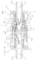
- FIG. 2 is a schematic perspective view showing the external appearance of the tube joint according to Embodiment 1 in an open state in which a flow path is open.
- FIG. 2 is a schematic cross-sectional view of the tube fitting in FIG. 1 in which the flow path is in an open state, taken from a direction perpendicular to the axial direction.
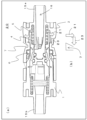
- (a) is a schematic cross-sectional view showing how the first outer circumferential member is pushed radially outward from the first spring storage portion and deformed when the internal fluid flowing inside the tube fitting shown in FIG. 2 expands in volume due to freezing.
- (b) is a schematic diagram showing how expansion in the radial direction of the first spring storage portion is converted into deformation in the axial direction of the recessed portion.
- FIG. 1 is a schematic perspective view showing the external appearance of the tube joint according to Embodiment 1 in an open state in which a flow path is open.
- FIG. 2 is a schematic cross-sectional view of the tube fitting in FIG. 1 in which the flow path
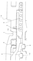
- FIG. 3 is an enlarged cross-sectional view showing a first spring, a first spring storage portion, and a recessed portion of the tube fitting shown in FIG. 2.
- FIG. FIG. 7 is a schematic perspective view showing the external appearance of the tube joint according to Embodiment 2 in an open state in which a flow path is open.
- FIG. 6 is a sectional view taken in a direction perpendicular to the axial direction of the tube joint in FIG. 5 in which the flow path is in an open state.
- the tube fitting according to the first aspect is a tube fitting for connecting tubes through which fluid flows, and has a first tube through which fluid flows, and has an axis in the insertion direction.
- a female connector having a concave inserted part in the direction, a second pipe through which fluid flows inside, and a convex insertion part inserted into and connected to the inserted part along the axial direction.
- a male connector, and the female connector includes a pressing member having a sealing member around the periphery, a spring having one end connected to the inserted part, and a spring connected to the other end of the spring and attached to the outside in the axial direction.
- an annular member that covers the outer seal member and the spring storage portion in the axial direction; It has a concave shape radially outwardly over at least a portion of the direction.
- the recessed portion may be configured to deform in the axial direction when the spring storage portion expands in the first aspect.
- the recess may be arranged at the same position in the axial direction as one end of the spring storage section.
- the outer peripheral member has an uneven portion on the outer periphery
- the inner periphery of the annular member has an uneven portion along the shape of the uneven portion. It may have a shape.
- the tube fitting according to the fifth aspect may further include a communication hole communicating with the inner circumferential side of the annular member on the radially outer side of the spring storage portion in any one of the first to fourth aspects. good.
- the tube fitting according to the sixth aspect may further include a heat insulating material disposed radially inside the spring storage portion in any one of the first to fifth aspects.
- the fluid in any one of the first to sixth aspects, may contain water.
- the spring storage portion includes the spring, the first tube on the inner circumference side of the spring, and the outer circumference on the outer circumference side of the spring. It may be defined by a member.
- FIG. 1 is a schematic perspective view showing the external appearance of a tube fitting 20 according to Embodiment 1 in an open state in which a flow path is open.
- FIG. 2 is a cross-sectional view of the tube fitting in which the flow path 18 of FIG. 1 is in an open state, taken in a direction perpendicular to the axial direction.
- the tube fitting 20 is a tube fitting for connecting two tubes (not shown) through which fluid flows.
- This tube fitting includes a female connector 1 having a first tube 16 through which fluid flows, and a recessed insertion portion 24 in the axial direction, which is the insertion direction, and a second tube through which fluid flows inside.
- the male connector 2 includes a tube 17 and a convex insertion portion 22 that is inserted into and connected to the inserted portion 24 along the axial direction.
- the female connector 1 includes a first pressing member 3 having a first sealing member 8 around it, a first spring 4 whose one end is connected to the inserted portion 24, a first outer peripheral member 19, and a first spring 4.
- the first spring storage part 5 to be stored, an external seal member, and an annular member 14 that covers the external seal member 6 and the first spring storage part 5 in the axial direction.
- the first outer circumferential member 19 is connected to the other end of the first spring 4 and is urged outward in the axial direction.
- the first seal member 8 contacts the first seal member 8 .
- the external seal member 6 seals the gap with the outside by sandwiching the first outer peripheral member 19 between it and the first pressing member 3.
- the annular member 14 has a concave recess 7 radially outward over at least a portion of the circumferential direction between the external seal member 6 and the first spring storage portion 5 in the axial direction.
- the annular member 14 has a concave portion 7 radially outwardly extending over at least a portion of the circumferential direction between the external seal member 6 and the first spring storage portion 5. . Therefore, even if volume expansion occurs due to freezing of the internal fluid containing water, expansion in the radial direction of the installation location of the external seal member 6 can be suppressed. Thereby, fluid leakage can be suppressed.
- the internal fluid flowing into the tube of this tube fitting 20 is water or a liquid containing water. In other words, it is a fluid that expands in volume when the internal fluid freezes at low temperatures.
- the female connector 1 has a first tube 16 through which fluid flows, and has an inserted portion 24 that is concave in the axial direction (X direction), into which an insertion portion 22 is inserted and connected. Further, it is connected to a tube (not shown) at the tube connection portion 15a at the end.
- the second tube 17 has fluid flowing from the tube tube.
- the inserted portion 24 is concave in the axial direction (X direction) and includes a first pressing member 3 , a first sealing member 8 , and a first outer peripheral member 19 .
- the first pressing member 3 has a convex shape in the axial direction, and is urged outward in the axial direction by the first spring 4 when the male connector 2 is not inserted into the female connector 1.
- the second pressing member 13 of the male connector 2 comes into contact with the first pressing member 3 of the female connector 1.
- the first pressing member 3 is located inside the inserted portion 24. As shown in FIG.
- the first sealing member 8 has an annular shape and is arranged around the first pressing member 3 .
- an O-ring can be used as the first seal member 8.
- the first seal member 8 is an example of an internal seal member.
- the first spring 4 has one end connected to the inserted portion 24 .
- the first spring 4 is arranged around the first tube 16.
- the first outer peripheral member 19 is biased by the first spring 4 in the opposite direction to the axial direction (insertion direction X). When the male connectors are separated, the first outer peripheral member 19 contacts the first sealing member 8 to prevent the first tube 16 of the female connector 1 and the second tube 17 of the male connector 2 from connecting. The flow path 18 between them is closed. This results in a closed state.
- the first outer peripheral member 19 is connected to one end 4a of the first spring 4 (see FIG. 2).
- the first outer peripheral member 19 is separated from the first seal member 8 and opens the flow path 18 between the first pipe 16 and the second pipe 17. do. This results in an open state.
- the first outer peripheral member 19 is connected to the first pressing member 3 via the first spring 4, and the first outer peripheral member 19 and the second pressing member 13 are connected to each other by the stretched state and compressed state of the second spring 10. The relative position in the axial direction changes.
- the first outer peripheral member 19 may have an uneven portion on its outer periphery, and the inner circumference of the annular member 14 may have an uneven shape that follows the shape of the uneven portion. That is, the first outer peripheral member 19 has an uneven shape on its outer peripheral surface.
- the annular member 14 has an uneven shape that follows the uneven shape of the first outer peripheral member 19 on the inner peripheral surface of the annular member 14 . Thereby, the volume between the first outer circumferential member 19 and the annular member 14 can be reduced, and expansion in the radial direction can be further suppressed.
- the first spring storage section 5 stores the first spring 4, and includes the first spring 4, a first tube 16 on the inner circumferential side of the first spring 4, and a first outer circumferential member 19 on the outer circumferential side of the first spring. defined by.
- ⁇ External seal member> As shown in FIGS. 2 and 4, between the first outer circumferential member 19 and the second outer circumferential member 9 and the annular member 14 of the female connector 1 surrounding the outer peripheries of the first outer circumferential member 19 and the second outer circumferential member 9, It further includes an external seal member 6 for sealing.
- the external seal member 6 contacts the first outer circumferential member 19 or the second outer circumferential member 9, and the first outer circumferential member 19 and the second outer circumferential member 9 shift in the axial direction. Therefore, the external seal member 6 has an X-shaped cross-section, for example.
- the external seal member 6 contacts the first outer circumferential member 19 or the second outer circumferential member 9 at two points in the axial direction, so that the sliding resistance in the axial direction is smaller than that of a normal circular shape. .
- the external seal member 6 contacts and seals the first outer circumferential member 19 or the second outer circumferential member 9, the first outer circumferential member 19 and the second outer circumferential member 9 are moved in the axial direction between the closed state and the open state. Liquid leakage can also be suppressed when shifted to . That is, the external seal member 6 seals the gap between the first outer peripheral member 19 and the annular member 14 when the male connector 2 is not inserted into the inserted portion 24 (open state).
- the annular member 14 covers the external seal member 6 and the first spring storage portion 5 in the axial direction.
- the annular member 14 has a concave portion 7 radially outwardly extending over at least a portion of the circumferential direction between the external seal member 6 and the first spring storage portion 5 in the axial direction.
- the recess 7 is recessed from the outer surface 14a of the annular member 14 in the radial direction of the annular member 14 (the direction perpendicular to the insertion direction X and toward the center of the annular member 14).
- the recess 7 is not limited to being provided over the entire circumference as shown in FIG. 2.
- it may have a concave shape over a portion of the circumferential direction.
- the recess 7 may be arranged at the same position as one end of the first spring storage section 5 in the axial direction. One end in this case is one end of the first spring 4 in a contracted state. Note that the recessed portion 7 is not limited to being exactly at the same position as one end of the first spring storage portion 5, and may partially overlap.
- the cross-sectional shape of the recess 7 is not limited to the rectangular shape shown in FIG. 2, but may be any one of a semicircular shape, a V-shape, a polygonal shape, and the like.
- FIG. 3(a) shows how the first outer circumferential member 19 is pushed radially outward from the first spring storage portion 5 and deformed when the internal fluid flowing inside the tube fitting 20 of FIG. 2 expands in volume due to freezing.
- (b) is a schematic diagram showing how the radial expansion of the first spring housing section 5 is converted into the axial deformation of the recessed section 7.
- FIG. 4 is an enlarged cross-sectional view showing the first spring 4, first spring storage portion 5, and recess 7 of the tube fitting shown in FIG.
- the first spring storage section 5 communicates with the first tube 16. That is, the first spring storage section 5 is configured such that the fluid flowing inside the first tube 16 enters the first spring storage section 5 .
- the recess 7 separates the external seal member 6, which is a sealing portion, from the first spring storage portion 5, which is expanded by a fluid containing water.
- the recess 7 is configured to deform in the opposite axial direction (the opposite direction to the insertion direction X) when the first spring storage section 5 expands.
- the internal fluid in the first spring storage section 5 expands in volume due to freezing, it deforms outward in the radial direction as shown by an arrow 21.
- This radially outward deformation 21 is converted into axial deformation 23 in the recess 7 provided in the annular member 14, as shown in the schematic diagram of FIG. 3(b).
- the male connector 2 has a second tube 17 through which fluid flows inside, and has an insertion portion 22 that is convex in the axial direction (X direction), which is the insertion direction X (see FIG. 2). Further, it is connected to a tube (not shown) at the tube connection portion 15b at the end.
- the second tube 17 has fluid flowing from the tube tube.
- the insertion portion 22 has a convex shape in the axial direction (X direction), and includes a second pressing member 13, a first sealing member 8, and a second outer peripheral member 9.
- the second pressing member 13 has a convex shape in the axial direction, and is biased outward in the axial direction (X direction) by the second spring 10 when the male connector 2 is not inserted into the female connector 1. ing.
- the second sealing member 12 has an annular shape and is arranged around the second pressing member 13 .
- an O-ring can be used.
- the second outer peripheral member 9 supports the second spring 10 in the axial direction (X direction), and is spaced apart from the second pressing member 13 and surrounds the periphery in the axial direction (X direction) in an annular shape.
- the second outer circumferential member 9 is connected to the second pressing member 13 via the second spring 10, and the second outer circumferential member 9 and the second pressing member 13 are connected to each other by the stretched state and compressed state of the second spring 10.
- the relative position in the axial direction changes.
- the insertion portion 22 may have a convex portion 30 on the side surface around the male connector 2 in the axial direction (X direction).
- the convex portion 30 is not limited to a circular shape, and may be a polygon such as a quadrangle. Note that friction can be reduced if the edges of the convex portions 30 are curved.
- the inserted portion 24 extends on the side surface around the female connector 1 in the axial direction (X direction) in a direction inclined with respect to the axial direction, and has a first movable convex portion 30.
- the through hole 25a may be provided.
- the male connector 2 is connected to the female connector 1 by the convex portion 30 being guided in the axial direction by the first through hole 25a of the female connector 1.
- the hole is provided along the axial direction, it is necessary to push the male connector 2 straight in the axial direction without rotating it, which requires a large amount of force.
- the first through hole 25a is provided at an angle with respect to the axial direction, it is possible to easily insert the male connector 2 in the axial direction using torque with little force while rotating the male connector 2. Furthermore, since the first through hole 25a is inclined with respect to the axial direction, the direction of rotation when pushing in the axial direction can be specified.
- a second through hole continues from the end 26b on the axial side of the first through hole 25a along the in-plane direction of the side surface, and extends in the circumferential direction substantially perpendicular to the axial direction on the side surface in the direction intersecting the axial direction. It may further include a hole 25b.
- the male connector 2 is connected to the female connector 1 by fixing the convex portion 30 in the axial direction by the second through hole 25b. Further, by providing the second through hole 25b so as to have a predetermined length in the circumferential direction, the position of the convex portion 30 in the circumferential direction can be adjusted. Thereby, twisting of the tube caused by rotation of the male connector 2 can be eliminated.
- the second through hole 25b may have an angle of 20° or more with respect to the axis, for example.
- FIG. 5 is a schematic perspective view showing the appearance of the tube fitting 20a according to the second embodiment in an open state in which the flow path 18 is open.
- FIG. 6 is a cross-sectional view of the tube fitting 20a in which the flow path 18 of FIG. 5 is in an open state, taken from a direction perpendicular to the axial direction.
- This tube fitting 20a is different from the tube fitting according to Embodiment 1 in that the recess 7a of the annular member 14 does not extend over the entire circumference, but has a concave shape over a part of the circumference. Furthermore, the ribs 32 that partition each recess 7a function as reinforcing ribs, and when the recess expands, it can suppress deformation in the radial direction and convert it into deformation in the axial direction.
- a communication hole 34 may be further provided on the radially outer side of the first spring storage portion 5 and communicated with the inner peripheral side of the annular member 14. That is, the first outer peripheral member 19 may have a communication hole 34 that communicates with the inner peripheral side of the annular member 14 . This has the effect that when the tube fitting 20a is exposed to low temperatures and freezes sequentially from the outside, the liquid on the inner peripheral side of the annular member 14 can escape inward.
- the ribs 32 corresponding to the locations where the communication holes 34 are provided, the liquid can escape inward at the locations where the communication holes 34 are provided, so that the amount of liquid present is small; The effect of suppressing deformation by the ribs 32 can further be obtained.
- a heat insulating material 36 may be further provided which is disposed inside the first spring storage section 5 in the radial direction. That is, the female connector 1 may further include a heat insulating material 36 stored in the first spring storage section 5 and disposed inside the first spring 4. As a result, even when freezing starts from the outside, the liquid on the inner circumference becomes difficult to freeze due to the heat shielding effect of the heat insulating material 36 placed on the inside in the radial direction, and when the liquid in the first spring housing section 5 freezes, Allows liquid to escape inside. This makes it possible to suppress expansion outward in the radial direction.
- the heat insulating material 36 for example, a rubber sheet can be used.
- the tube joint according to the present disclosure even if volumetric expansion occurs due to freezing of the internal fluid containing water, expansion in the radial direction of the installation location of the external seal member can be suppressed. Therefore, it is useful as a joint for circulating internal fluid containing water.
- Second connector 1 Female connector 2 Male connector 3 First pressing member 4 First spring 5 First spring storage 6 External seal members 7, 7a Recess 8 First seal member 9 Second outer peripheral member 10 Second spring 11 Second spring storage Part 12 Second sealing member 13 Second pressing member 14 Annular member 15a, 15b Tube connection part 16 First pipe 17 Second pipe 18 Flow path 19 First outer peripheral member 20, 20a Tube joint 21 To the outside in the radial direction Deformation 22 Insert portion 23 Axial deformation 24 Inserted portion 25a First through hole 25b Second through hole 26a Front end 26b Axial end 28 Outer member 30 Convex portion 32 Rib 34 Communication hole 36 insulation material
Landscapes
- Engineering & Computer Science (AREA)
- General Engineering & Computer Science (AREA)
- Mechanical Engineering (AREA)
- Quick-Acting Or Multi-Walled Pipe Joints (AREA)
Priority Applications (2)
| Application Number | Priority Date | Filing Date | Title |
|---|---|---|---|
| JP2024537623A JPWO2024024580A1 (https=) | 2022-07-25 | 2023-07-18 | |
| US19/020,495 US20250146609A1 (en) | 2022-07-25 | 2025-01-14 | Tube joint |
Applications Claiming Priority (2)
| Application Number | Priority Date | Filing Date | Title |
|---|---|---|---|
| JP2022-118116 | 2022-07-25 | ||
| JP2022118116 | 2022-07-25 |
Related Child Applications (1)
| Application Number | Title | Priority Date | Filing Date |
|---|---|---|---|
| US19/020,495 Continuation US20250146609A1 (en) | 2022-07-25 | 2025-01-14 | Tube joint |
Publications (1)
| Publication Number | Publication Date |
|---|---|
| WO2024024580A1 true WO2024024580A1 (ja) | 2024-02-01 |
Family
ID=89706252
Family Applications (1)
| Application Number | Title | Priority Date | Filing Date |
|---|---|---|---|
| PCT/JP2023/026313 Ceased WO2024024580A1 (ja) | 2022-07-25 | 2023-07-18 | チューブ管用継手 |
Country Status (3)
| Country | Link |
|---|---|
| US (1) | US20250146609A1 (https=) |
| JP (1) | JPWO2024024580A1 (https=) |
| WO (1) | WO2024024580A1 (https=) |
Citations (5)
| Publication number | Priority date | Publication date | Assignee | Title |
|---|---|---|---|---|
| JPH0267194U (https=) * | 1988-11-11 | 1990-05-21 | ||
| JP2000055273A (ja) * | 1998-08-10 | 2000-02-22 | Kyouseki Sangyo Kk | 自己シール型一重管継手 |
| JP2016089932A (ja) * | 2014-11-04 | 2016-05-23 | 株式会社ブリヂストン | 管継手 |
| CN210462080U (zh) * | 2019-09-06 | 2020-05-05 | 万硕(成都)航空科技有限公司 | 一种大浮动带压插拔流体连接器 |
| CN113566040A (zh) * | 2021-08-02 | 2021-10-29 | 瑞肯耐特流体控制系统(镇江)有限公司 | 连接器组件 |
Family Cites Families (1)
| Publication number | Priority date | Publication date | Assignee | Title |
|---|---|---|---|---|
| IT1289947B1 (it) * | 1997-02-21 | 1998-10-19 | Faster Srl | Innesto rapido |
-
2023
- 2023-07-18 JP JP2024537623A patent/JPWO2024024580A1/ja active Pending
- 2023-07-18 WO PCT/JP2023/026313 patent/WO2024024580A1/ja not_active Ceased
-
2025
- 2025-01-14 US US19/020,495 patent/US20250146609A1/en active Pending
Patent Citations (5)
| Publication number | Priority date | Publication date | Assignee | Title |
|---|---|---|---|---|
| JPH0267194U (https=) * | 1988-11-11 | 1990-05-21 | ||
| JP2000055273A (ja) * | 1998-08-10 | 2000-02-22 | Kyouseki Sangyo Kk | 自己シール型一重管継手 |
| JP2016089932A (ja) * | 2014-11-04 | 2016-05-23 | 株式会社ブリヂストン | 管継手 |
| CN210462080U (zh) * | 2019-09-06 | 2020-05-05 | 万硕(成都)航空科技有限公司 | 一种大浮动带压插拔流体连接器 |
| CN113566040A (zh) * | 2021-08-02 | 2021-10-29 | 瑞肯耐特流体控制系统(镇江)有限公司 | 连接器组件 |
Also Published As
| Publication number | Publication date |
|---|---|
| US20250146609A1 (en) | 2025-05-08 |
| JPWO2024024580A1 (https=) | 2024-02-01 |
Similar Documents
| Publication | Publication Date | Title |
|---|---|---|
| EP1363061B1 (en) | Fluid line assembly | |
| RU2270392C2 (ru) | Уплотнение для входа кабеля, подводки трубы или т.п. | |
| US6361049B1 (en) | Recessed groove/seal surface for seal effectiveness | |
| US5299841A (en) | Safety flow restrictor for expansion joints | |
| US5131695A (en) | Coupling with teflon seat | |
| CN110621920A (zh) | 用于垫圈的密封构件及包括其的垫圈 | |
| CN112096871B (zh) | 自紧式密封件 | |
| CN109155513A (zh) | 镶件半部和包括两个所述镶件半部的镶块 | |
| CA2377737C (en) | Ultra-flexible gasket for liquid natural gas processing plants | |
| US2638243A (en) | Sealing means for cooperatively assembled parts of valve or comparable assemblies | |
| WO2024024580A1 (ja) | チューブ管用継手 | |
| JP3553713B2 (ja) | 流体管のシール構造 | |
| BRPI0900987A2 (pt) | vedação de sonda com elementos de vedação energizados por mola para elemento de acoplamento hidráulico fêmea | |
| EP0029686B1 (en) | Continuous self-locking spiral wound seal | |
| JP6748791B2 (ja) | 管継手 | |
| US7090258B2 (en) | Sealing socket and method for arranging a sealing socket to a tube | |
| KR20200002114U (ko) | 주름관 연결 구조체 | |
| JPH0614144Y2 (ja) | 回転部分のシール装置 | |
| CN113685638A (zh) | 一种低流阻高承压盲插接头 | |
| CN113819332B (zh) | 管路密封结构和管路组件 | |
| JP2010249212A (ja) | フレキシブルチューブ用継手装置 | |
| JP2007040349A (ja) | フレキシブルチューブ用継手 | |
| JP7246692B2 (ja) | 二重管継手構造 | |
| CN209781942U (zh) | 密封连接结构以及具有其的电池包 | |
| KR200228268Y1 (ko) | 배관 조인트 링 |
Legal Events
| Date | Code | Title | Description |
|---|---|---|---|
| 121 | Ep: the epo has been informed by wipo that ep was designated in this application |
Ref document number: 23846311 Country of ref document: EP Kind code of ref document: A1 |
|
| WWE | Wipo information: entry into national phase |
Ref document number: 2024537623 Country of ref document: JP |
|
| NENP | Non-entry into the national phase |
Ref country code: DE |
|
| 122 | Ep: pct application non-entry in european phase |
Ref document number: 23846311 Country of ref document: EP Kind code of ref document: A1 |