WO2024024580A1 - Tube joint - Google Patents
Tube joint Download PDFInfo
- Publication number
- WO2024024580A1 WO2024024580A1 PCT/JP2023/026313 JP2023026313W WO2024024580A1 WO 2024024580 A1 WO2024024580 A1 WO 2024024580A1 JP 2023026313 W JP2023026313 W JP 2023026313W WO 2024024580 A1 WO2024024580 A1 WO 2024024580A1
- Authority
- WO
- WIPO (PCT)
- Prior art keywords
- spring
- axial direction
- tube
- outer peripheral
- male connector
- Prior art date
Links
- 238000003780 insertion Methods 0.000 claims abstract description 23
- 230000037431 insertion Effects 0.000 claims abstract description 23
- 238000007789 sealing Methods 0.000 claims abstract description 19
- 230000002093 peripheral effect Effects 0.000 claims description 41
- 239000012530 fluid Substances 0.000 claims description 38
- XLYOFNOQVPJJNP-UHFFFAOYSA-N water Substances O XLYOFNOQVPJJNP-UHFFFAOYSA-N 0.000 claims description 12
- 239000012212 insulator Substances 0.000 claims 1
- 238000007710 freezing Methods 0.000 description 10
- 230000008014 freezing Effects 0.000 description 10
- 239000007788 liquid Substances 0.000 description 8
- 238000009434 installation Methods 0.000 description 6
- 239000011810 insulating material Substances 0.000 description 5
- 230000000694 effects Effects 0.000 description 4
- 230000006378 damage Effects 0.000 description 3
- 238000010586 diagram Methods 0.000 description 3
- 230000004308 accommodation Effects 0.000 description 1
- 238000001816 cooling Methods 0.000 description 1
- 239000012774 insulation material Substances 0.000 description 1
- 238000005192 partition Methods 0.000 description 1
- 230000003014 reinforcing effect Effects 0.000 description 1
Images


Classifications
-
- F—MECHANICAL ENGINEERING; LIGHTING; HEATING; WEAPONS; BLASTING
- F16—ENGINEERING ELEMENTS AND UNITS; GENERAL MEASURES FOR PRODUCING AND MAINTAINING EFFECTIVE FUNCTIONING OF MACHINES OR INSTALLATIONS; THERMAL INSULATION IN GENERAL
- F16L—PIPES; JOINTS OR FITTINGS FOR PIPES; SUPPORTS FOR PIPES, CABLES OR PROTECTIVE TUBING; MEANS FOR THERMAL INSULATION IN GENERAL
- F16L37/00—Couplings of the quick-acting type
- F16L37/28—Couplings of the quick-acting type with fluid cut-off means
- F16L37/30—Couplings of the quick-acting type with fluid cut-off means with fluid cut-off means in each of two pipe-end fittings
- F16L37/367—Couplings of the quick-acting type with fluid cut-off means with fluid cut-off means in each of two pipe-end fittings with two gate valves or sliding valves
Definitions
- the present disclosure relates to a tube fitting having a connectable male connector and a female connector.
- a pressure equalizing chamber is provided between a first connecting end and a second connecting end, a compressible insert is disposed within the pressure equalizing chamber, and the equalizing insert is disposed in the pressure equalizing chamber.
- a joint is disclosed in which a fluid medium flows between an inner wall of a pressure chamber and a compressible insert (see, for example, Patent Document 1). According to this joint, the compressible insert is compressed during volume expansion due to the temperature of the fluid medium, and it is said that damage and destruction during freezing can be prevented.
- An object of the present disclosure is to provide a tube joint that can suppress expansion in the radial direction of the installation location of an external seal member even if volume expansion occurs due to freezing of an internal fluid containing water.
- a tube fitting according to the present disclosure is a tube fitting for connecting two tubes through which fluid flows, and has a first tube through which fluid flows, and has an axis in the insertion direction.
- a female connector having a concave insertion part in the axial direction;
- a convex connector having a second tube through which a fluid flows; the connector is inserted into the insertion part along the axial direction and connected to the insertion part
- a male connector having an insertion portion.
- the female connector is connected to a pressing member located inside the inserted portion, an internal seal member placed around the pressing member, a spring placed around the first tube, and one end of the spring, an outer circumferential member that is biased in the opposite axial direction by a spring and comes into contact with the internal sealing member when the male connector is not inserted into the inserted portion; a spring storage portion that stores the spring; and a male connector.
- the device further includes an external seal member that seals a gap between the female connector and the male connector when the connector is inserted into the inserted portion, and an annular member that covers the external seal member and the spring storage portion. The external seal member seals the gap between the outer peripheral member and the annular member when the male connector is not inserted into the inserted portion.
- the annular member has a recess located between the outer seal member and the spring housing in the axial direction.
- the recess is recessed from the outer surface of the annular member in the radial direction of the annular member over at least a portion of the circumferential direction of the annular member.
- the annular member has a concave portion radially outward over at least a portion of the circumferential direction between the external seal member and the spring storage portion. Therefore, even if volume expansion occurs due to freezing of the internal fluid containing water, expansion in the radial direction of the installation location of the external seal member can be suppressed.
- FIG. 2 is a schematic perspective view showing the external appearance of the tube joint according to Embodiment 1 in an open state in which a flow path is open.
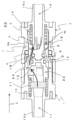
- FIG. 2 is a schematic cross-sectional view of the tube fitting in FIG. 1 in which the flow path is in an open state, taken from a direction perpendicular to the axial direction.
- (a) is a schematic cross-sectional view showing how the first outer circumferential member is pushed radially outward from the first spring storage portion and deformed when the internal fluid flowing inside the tube fitting shown in FIG. 2 expands in volume due to freezing.
- (b) is a schematic diagram showing how expansion in the radial direction of the first spring storage portion is converted into deformation in the axial direction of the recessed portion.
- FIG. 1 is a schematic perspective view showing the external appearance of the tube joint according to Embodiment 1 in an open state in which a flow path is open.
- FIG. 2 is a schematic cross-sectional view of the tube fitting in FIG. 1 in which the flow path
- FIG. 3 is an enlarged cross-sectional view showing a first spring, a first spring storage portion, and a recessed portion of the tube fitting shown in FIG. 2.
- FIG. FIG. 7 is a schematic perspective view showing the external appearance of the tube joint according to Embodiment 2 in an open state in which a flow path is open.
- FIG. 6 is a sectional view taken in a direction perpendicular to the axial direction of the tube joint in FIG. 5 in which the flow path is in an open state.
- the tube fitting according to the first aspect is a tube fitting for connecting tubes through which fluid flows, and has a first tube through which fluid flows, and has an axis in the insertion direction.
- a female connector having a concave inserted part in the direction, a second pipe through which fluid flows inside, and a convex insertion part inserted into and connected to the inserted part along the axial direction.
- a male connector, and the female connector includes a pressing member having a sealing member around the periphery, a spring having one end connected to the inserted part, and a spring connected to the other end of the spring and attached to the outside in the axial direction.
- an annular member that covers the outer seal member and the spring storage portion in the axial direction; It has a concave shape radially outwardly over at least a portion of the direction.
- the recessed portion may be configured to deform in the axial direction when the spring storage portion expands in the first aspect.
- the recess may be arranged at the same position in the axial direction as one end of the spring storage section.
- the outer peripheral member has an uneven portion on the outer periphery
- the inner periphery of the annular member has an uneven portion along the shape of the uneven portion. It may have a shape.
- the tube fitting according to the fifth aspect may further include a communication hole communicating with the inner circumferential side of the annular member on the radially outer side of the spring storage portion in any one of the first to fourth aspects. good.
- the tube fitting according to the sixth aspect may further include a heat insulating material disposed radially inside the spring storage portion in any one of the first to fifth aspects.
- the fluid in any one of the first to sixth aspects, may contain water.
- the spring storage portion includes the spring, the first tube on the inner circumference side of the spring, and the outer circumference on the outer circumference side of the spring. It may be defined by a member.
- FIG. 1 is a schematic perspective view showing the external appearance of a tube fitting 20 according to Embodiment 1 in an open state in which a flow path is open.
- FIG. 2 is a cross-sectional view of the tube fitting in which the flow path 18 of FIG. 1 is in an open state, taken in a direction perpendicular to the axial direction.
- the tube fitting 20 is a tube fitting for connecting two tubes (not shown) through which fluid flows.
- This tube fitting includes a female connector 1 having a first tube 16 through which fluid flows, and a recessed insertion portion 24 in the axial direction, which is the insertion direction, and a second tube through which fluid flows inside.
- the male connector 2 includes a tube 17 and a convex insertion portion 22 that is inserted into and connected to the inserted portion 24 along the axial direction.
- the female connector 1 includes a first pressing member 3 having a first sealing member 8 around it, a first spring 4 whose one end is connected to the inserted portion 24, a first outer peripheral member 19, and a first spring 4.
- the first spring storage part 5 to be stored, an external seal member, and an annular member 14 that covers the external seal member 6 and the first spring storage part 5 in the axial direction.
- the first outer circumferential member 19 is connected to the other end of the first spring 4 and is urged outward in the axial direction.
- the first seal member 8 contacts the first seal member 8 .
- the external seal member 6 seals the gap with the outside by sandwiching the first outer peripheral member 19 between it and the first pressing member 3.
- the annular member 14 has a concave recess 7 radially outward over at least a portion of the circumferential direction between the external seal member 6 and the first spring storage portion 5 in the axial direction.
- the annular member 14 has a concave portion 7 radially outwardly extending over at least a portion of the circumferential direction between the external seal member 6 and the first spring storage portion 5. . Therefore, even if volume expansion occurs due to freezing of the internal fluid containing water, expansion in the radial direction of the installation location of the external seal member 6 can be suppressed. Thereby, fluid leakage can be suppressed.
- the internal fluid flowing into the tube of this tube fitting 20 is water or a liquid containing water. In other words, it is a fluid that expands in volume when the internal fluid freezes at low temperatures.
- the female connector 1 has a first tube 16 through which fluid flows, and has an inserted portion 24 that is concave in the axial direction (X direction), into which an insertion portion 22 is inserted and connected. Further, it is connected to a tube (not shown) at the tube connection portion 15a at the end.
- the second tube 17 has fluid flowing from the tube tube.
- the inserted portion 24 is concave in the axial direction (X direction) and includes a first pressing member 3 , a first sealing member 8 , and a first outer peripheral member 19 .
- the first pressing member 3 has a convex shape in the axial direction, and is urged outward in the axial direction by the first spring 4 when the male connector 2 is not inserted into the female connector 1.
- the second pressing member 13 of the male connector 2 comes into contact with the first pressing member 3 of the female connector 1.
- the first pressing member 3 is located inside the inserted portion 24. As shown in FIG.
- the first sealing member 8 has an annular shape and is arranged around the first pressing member 3 .
- an O-ring can be used as the first seal member 8.
- the first seal member 8 is an example of an internal seal member.
- the first spring 4 has one end connected to the inserted portion 24 .
- the first spring 4 is arranged around the first tube 16.
- the first outer peripheral member 19 is biased by the first spring 4 in the opposite direction to the axial direction (insertion direction X). When the male connectors are separated, the first outer peripheral member 19 contacts the first sealing member 8 to prevent the first tube 16 of the female connector 1 and the second tube 17 of the male connector 2 from connecting. The flow path 18 between them is closed. This results in a closed state.
- the first outer peripheral member 19 is connected to one end 4a of the first spring 4 (see FIG. 2).
- the first outer peripheral member 19 is separated from the first seal member 8 and opens the flow path 18 between the first pipe 16 and the second pipe 17. do. This results in an open state.
- the first outer peripheral member 19 is connected to the first pressing member 3 via the first spring 4, and the first outer peripheral member 19 and the second pressing member 13 are connected to each other by the stretched state and compressed state of the second spring 10. The relative position in the axial direction changes.
- the first outer peripheral member 19 may have an uneven portion on its outer periphery, and the inner circumference of the annular member 14 may have an uneven shape that follows the shape of the uneven portion. That is, the first outer peripheral member 19 has an uneven shape on its outer peripheral surface.
- the annular member 14 has an uneven shape that follows the uneven shape of the first outer peripheral member 19 on the inner peripheral surface of the annular member 14 . Thereby, the volume between the first outer circumferential member 19 and the annular member 14 can be reduced, and expansion in the radial direction can be further suppressed.
- the first spring storage section 5 stores the first spring 4, and includes the first spring 4, a first tube 16 on the inner circumferential side of the first spring 4, and a first outer circumferential member 19 on the outer circumferential side of the first spring. defined by.
- ⁇ External seal member> As shown in FIGS. 2 and 4, between the first outer circumferential member 19 and the second outer circumferential member 9 and the annular member 14 of the female connector 1 surrounding the outer peripheries of the first outer circumferential member 19 and the second outer circumferential member 9, It further includes an external seal member 6 for sealing.
- the external seal member 6 contacts the first outer circumferential member 19 or the second outer circumferential member 9, and the first outer circumferential member 19 and the second outer circumferential member 9 shift in the axial direction. Therefore, the external seal member 6 has an X-shaped cross-section, for example.
- the external seal member 6 contacts the first outer circumferential member 19 or the second outer circumferential member 9 at two points in the axial direction, so that the sliding resistance in the axial direction is smaller than that of a normal circular shape. .
- the external seal member 6 contacts and seals the first outer circumferential member 19 or the second outer circumferential member 9, the first outer circumferential member 19 and the second outer circumferential member 9 are moved in the axial direction between the closed state and the open state. Liquid leakage can also be suppressed when shifted to . That is, the external seal member 6 seals the gap between the first outer peripheral member 19 and the annular member 14 when the male connector 2 is not inserted into the inserted portion 24 (open state).
- the annular member 14 covers the external seal member 6 and the first spring storage portion 5 in the axial direction.
- the annular member 14 has a concave portion 7 radially outwardly extending over at least a portion of the circumferential direction between the external seal member 6 and the first spring storage portion 5 in the axial direction.
- the recess 7 is recessed from the outer surface 14a of the annular member 14 in the radial direction of the annular member 14 (the direction perpendicular to the insertion direction X and toward the center of the annular member 14).
- the recess 7 is not limited to being provided over the entire circumference as shown in FIG. 2.
- it may have a concave shape over a portion of the circumferential direction.
- the recess 7 may be arranged at the same position as one end of the first spring storage section 5 in the axial direction. One end in this case is one end of the first spring 4 in a contracted state. Note that the recessed portion 7 is not limited to being exactly at the same position as one end of the first spring storage portion 5, and may partially overlap.
- the cross-sectional shape of the recess 7 is not limited to the rectangular shape shown in FIG. 2, but may be any one of a semicircular shape, a V-shape, a polygonal shape, and the like.
- FIG. 3(a) shows how the first outer circumferential member 19 is pushed radially outward from the first spring storage portion 5 and deformed when the internal fluid flowing inside the tube fitting 20 of FIG. 2 expands in volume due to freezing.
- (b) is a schematic diagram showing how the radial expansion of the first spring housing section 5 is converted into the axial deformation of the recessed section 7.
- FIG. 4 is an enlarged cross-sectional view showing the first spring 4, first spring storage portion 5, and recess 7 of the tube fitting shown in FIG.
- the first spring storage section 5 communicates with the first tube 16. That is, the first spring storage section 5 is configured such that the fluid flowing inside the first tube 16 enters the first spring storage section 5 .
- the recess 7 separates the external seal member 6, which is a sealing portion, from the first spring storage portion 5, which is expanded by a fluid containing water.
- the recess 7 is configured to deform in the opposite axial direction (the opposite direction to the insertion direction X) when the first spring storage section 5 expands.
- the internal fluid in the first spring storage section 5 expands in volume due to freezing, it deforms outward in the radial direction as shown by an arrow 21.
- This radially outward deformation 21 is converted into axial deformation 23 in the recess 7 provided in the annular member 14, as shown in the schematic diagram of FIG. 3(b).
- the male connector 2 has a second tube 17 through which fluid flows inside, and has an insertion portion 22 that is convex in the axial direction (X direction), which is the insertion direction X (see FIG. 2). Further, it is connected to a tube (not shown) at the tube connection portion 15b at the end.
- the second tube 17 has fluid flowing from the tube tube.
- the insertion portion 22 has a convex shape in the axial direction (X direction), and includes a second pressing member 13, a first sealing member 8, and a second outer peripheral member 9.
- the second pressing member 13 has a convex shape in the axial direction, and is biased outward in the axial direction (X direction) by the second spring 10 when the male connector 2 is not inserted into the female connector 1. ing.
- the second sealing member 12 has an annular shape and is arranged around the second pressing member 13 .
- an O-ring can be used.
- the second outer peripheral member 9 supports the second spring 10 in the axial direction (X direction), and is spaced apart from the second pressing member 13 and surrounds the periphery in the axial direction (X direction) in an annular shape.
- the second outer circumferential member 9 is connected to the second pressing member 13 via the second spring 10, and the second outer circumferential member 9 and the second pressing member 13 are connected to each other by the stretched state and compressed state of the second spring 10.
- the relative position in the axial direction changes.
- the insertion portion 22 may have a convex portion 30 on the side surface around the male connector 2 in the axial direction (X direction).
- the convex portion 30 is not limited to a circular shape, and may be a polygon such as a quadrangle. Note that friction can be reduced if the edges of the convex portions 30 are curved.
- the inserted portion 24 extends on the side surface around the female connector 1 in the axial direction (X direction) in a direction inclined with respect to the axial direction, and has a first movable convex portion 30.
- the through hole 25a may be provided.
- the male connector 2 is connected to the female connector 1 by the convex portion 30 being guided in the axial direction by the first through hole 25a of the female connector 1.
- the hole is provided along the axial direction, it is necessary to push the male connector 2 straight in the axial direction without rotating it, which requires a large amount of force.
- the first through hole 25a is provided at an angle with respect to the axial direction, it is possible to easily insert the male connector 2 in the axial direction using torque with little force while rotating the male connector 2. Furthermore, since the first through hole 25a is inclined with respect to the axial direction, the direction of rotation when pushing in the axial direction can be specified.
- a second through hole continues from the end 26b on the axial side of the first through hole 25a along the in-plane direction of the side surface, and extends in the circumferential direction substantially perpendicular to the axial direction on the side surface in the direction intersecting the axial direction. It may further include a hole 25b.
- the male connector 2 is connected to the female connector 1 by fixing the convex portion 30 in the axial direction by the second through hole 25b. Further, by providing the second through hole 25b so as to have a predetermined length in the circumferential direction, the position of the convex portion 30 in the circumferential direction can be adjusted. Thereby, twisting of the tube caused by rotation of the male connector 2 can be eliminated.
- the second through hole 25b may have an angle of 20° or more with respect to the axis, for example.
- FIG. 5 is a schematic perspective view showing the appearance of the tube fitting 20a according to the second embodiment in an open state in which the flow path 18 is open.
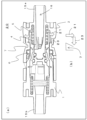
- FIG. 6 is a cross-sectional view of the tube fitting 20a in which the flow path 18 of FIG. 5 is in an open state, taken from a direction perpendicular to the axial direction.
- This tube fitting 20a is different from the tube fitting according to Embodiment 1 in that the recess 7a of the annular member 14 does not extend over the entire circumference, but has a concave shape over a part of the circumference. Furthermore, the ribs 32 that partition each recess 7a function as reinforcing ribs, and when the recess expands, it can suppress deformation in the radial direction and convert it into deformation in the axial direction.
- a communication hole 34 may be further provided on the radially outer side of the first spring storage portion 5 and communicated with the inner peripheral side of the annular member 14. That is, the first outer peripheral member 19 may have a communication hole 34 that communicates with the inner peripheral side of the annular member 14 . This has the effect that when the tube fitting 20a is exposed to low temperatures and freezes sequentially from the outside, the liquid on the inner peripheral side of the annular member 14 can escape inward.
- the ribs 32 corresponding to the locations where the communication holes 34 are provided, the liquid can escape inward at the locations where the communication holes 34 are provided, so that the amount of liquid present is small; The effect of suppressing deformation by the ribs 32 can further be obtained.
- a heat insulating material 36 may be further provided which is disposed inside the first spring storage section 5 in the radial direction. That is, the female connector 1 may further include a heat insulating material 36 stored in the first spring storage section 5 and disposed inside the first spring 4. As a result, even when freezing starts from the outside, the liquid on the inner circumference becomes difficult to freeze due to the heat shielding effect of the heat insulating material 36 placed on the inside in the radial direction, and when the liquid in the first spring housing section 5 freezes, Allows liquid to escape inside. This makes it possible to suppress expansion outward in the radial direction.
- the heat insulating material 36 for example, a rubber sheet can be used.
- the tube joint according to the present disclosure even if volumetric expansion occurs due to freezing of the internal fluid containing water, expansion in the radial direction of the installation location of the external seal member can be suppressed. Therefore, it is useful as a joint for circulating internal fluid containing water.
- Second connector 1 Female connector 2 Male connector 3 First pressing member 4 First spring 5 First spring storage 6 External seal members 7, 7a Recess 8 First seal member 9 Second outer peripheral member 10 Second spring 11 Second spring storage Part 12 Second sealing member 13 Second pressing member 14 Annular member 15a, 15b Tube connection part 16 First pipe 17 Second pipe 18 Flow path 19 First outer peripheral member 20, 20a Tube joint 21 To the outside in the radial direction Deformation 22 Insert portion 23 Axial deformation 24 Inserted portion 25a First through hole 25b Second through hole 26a Front end 26b Axial end 28 Outer member 30 Convex portion 32 Rib 34 Communication hole 36 insulation material
Landscapes
- Engineering & Computer Science (AREA)
- General Engineering & Computer Science (AREA)
- Mechanical Engineering (AREA)
- Quick-Acting Or Multi-Walled Pipe Joints (AREA)
Abstract
This tube joint for connecting two tubes comprises: a female connector including an inserted portion that is recessed in an axial direction, which is an insertion direction; and a male connector having a protruding insertion portion that is inserted into the inserted portion in the axial direction. The female connector additionally comprises: a pressing member; an internal sealing member; a spring; an outer circumferential member which is connected to one end of the spring, is urged in the opposite direction to the axial direction, and abuts the internal sealing member when the male connector has not been inserted; a spring accommodating portion; an external sealing member which seals a gap between the female connector and the male connector when the male connector has been inserted; and an annular member which covers the external sealing member and the spring accommodating portion. The annular member has a recessed portion positioned between the external sealing member and the spring accommodating portion in the axial direction.
Description
本開示は、連結可能な雄型コネクタ及び雌型コネクタを有するチューブ管用継手に関する。
The present disclosure relates to a tube fitting having a connectable male connector and a female connector.
チューブ管を流れる内部流体として水を含む媒体の場合には、低い温度の場合に容積を膨張させて凍結するという問題がある。この容積膨張を伴う凍結の際の圧力によって継手が損傷または破壊されることがある。
In the case of a medium containing water as an internal fluid flowing through a tube, there is a problem that it expands in volume and freezes at low temperatures. The pressure during freezing that accompanies this volumetric expansion can damage or destroy the joint.
従来、2つの流動媒体用収容要素を連結するための継手において、第1接続端部と第2接続端部との間に均圧室を備え、均圧室内に圧縮性インサートが配置され、均圧室の内壁と圧縮性インサートとの間に流動媒体が流れる継手が開示されている(例えば、特許文献1参照。)。この継手によれば、流動媒体の温度に起因する容積膨張の際に、圧縮性インサートが圧縮され、凍結時の損傷や破壊を防止できるとされている。
Conventionally, in a joint for connecting two fluid medium accommodation elements, a pressure equalizing chamber is provided between a first connecting end and a second connecting end, a compressible insert is disposed within the pressure equalizing chamber, and the equalizing insert is disposed in the pressure equalizing chamber. A joint is disclosed in which a fluid medium flows between an inner wall of a pressure chamber and a compressible insert (see, for example, Patent Document 1). According to this joint, the compressible insert is compressed during volume expansion due to the temperature of the fluid medium, and it is said that damage and destruction during freezing can be prevented.
しかし、上記従来の継手では、容積膨張を緩和する均圧スペースを設けるとともに、適切な硬さのインサート部材が必要であり、部品数が増えること、継手が大型化することなどの問題があった。そのため、電子機器内等の冷却用配管など、狭いスペースでの設置、着脱作業に適していなかった。
However, the above-mentioned conventional joints require the provision of a pressure-equalizing space to alleviate volumetric expansion, as well as insert members of appropriate hardness, resulting in problems such as an increase in the number of parts and an increase in the size of the joint. . Therefore, it was not suitable for installation or attachment/detachment work in narrow spaces, such as cooling piping inside electronic equipment.
また、電子機器内では、水漏れを発生させられないという制約があった。
Additionally, there was a restriction that water leakage could not occur inside electronic equipment.
本開示は、水を含む内部流体の凍結による容積膨張が生じても、外部シール部材の設置箇所の半径方向への膨張を抑制できるチューブ管用継手を提供することを目的とする。
An object of the present disclosure is to provide a tube joint that can suppress expansion in the radial direction of the installation location of an external seal member even if volume expansion occurs due to freezing of an internal fluid containing water.
本開示に係るチューブ管用継手は、内部に流体を流す2つのチューブ管を繋げて連結するためのチューブ管用継手であって、内側に流体が流れる第1の管を有し、挿入方向である軸方向に凹状の被挿入部を有する、雌型コネクタと、内側に流体が流れる第2の管を有し、軸方向に沿って被挿入部に挿入されて被挿入部と連結する、凸状の挿入部を有する、雄型コネクタと、を備える。雌型コネクタは、被挿入部の内側に位置する押圧部材と、押圧部材の周囲に配置された内部シール部材と、第1の管の周囲に配置されたバネと、バネの一端に接続され、バネによって軸方向の反対方向に付勢され、雄型コネクタを被挿入部に挿入していない状態において、内部シール部材と当接する、外周部材と、バネを格納するバネ格納部と、雄型コネクタを被挿入部に挿入した際に、雌型コネクタと前記雄型コネクタとの隙間をシールする外部シール部材と、外部シール部材とバネ格納部とを覆う環状部材と、をさらに有する。外部シール部材は、雄型コネクタを被挿入部に挿入していない状態において、外周部材と環状部材との隙間をシールする。環状部材は、軸方向における外部シール部材とバネ格納部との間に位置する凹部を有する。凹部は、環状部材の円周方向の少なくとも一部にわたって、環状部材の外表面から環状部材の半径方向に凹んでいる。
A tube fitting according to the present disclosure is a tube fitting for connecting two tubes through which fluid flows, and has a first tube through which fluid flows, and has an axis in the insertion direction. a female connector having a concave insertion part in the axial direction; a convex connector having a second tube through which a fluid flows; the connector is inserted into the insertion part along the axial direction and connected to the insertion part A male connector having an insertion portion. The female connector is connected to a pressing member located inside the inserted portion, an internal seal member placed around the pressing member, a spring placed around the first tube, and one end of the spring, an outer circumferential member that is biased in the opposite axial direction by a spring and comes into contact with the internal sealing member when the male connector is not inserted into the inserted portion; a spring storage portion that stores the spring; and a male connector. The device further includes an external seal member that seals a gap between the female connector and the male connector when the connector is inserted into the inserted portion, and an annular member that covers the external seal member and the spring storage portion. The external seal member seals the gap between the outer peripheral member and the annular member when the male connector is not inserted into the inserted portion. The annular member has a recess located between the outer seal member and the spring housing in the axial direction. The recess is recessed from the outer surface of the annular member in the radial direction of the annular member over at least a portion of the circumferential direction of the annular member.
本開示に係るチューブ管用継手によれば、環状部材は、外部シール部材とバネ格納部との間において、円周方向の少なくとも一部にわたって半径方向外側に凹形状の凹部を有する。そこで、水を含む内部流体の凍結による容積膨張が生じても、外部シール部材の設置箇所の半径方向への膨張を抑制できる。
According to the tube joint according to the present disclosure, the annular member has a concave portion radially outward over at least a portion of the circumferential direction between the external seal member and the spring storage portion. Therefore, even if volume expansion occurs due to freezing of the internal fluid containing water, expansion in the radial direction of the installation location of the external seal member can be suppressed.
第1の態様に係るチューブ管用継手は、内部に流体を流すチューブ管を繋げて連結するためのチューブ管用継手であって、内側に流体が流れる第1の管を有し、挿入方向である軸方向に凹状の被挿入部を有する、雌型コネクタと、内側に流体が流れる第2の管を有し、軸方向に沿って被挿入部に挿入されて連結する、凸状の挿入部を有する、雄型コネクタと、を備え、雌型コネクタは、周囲にシール部材を有する押圧部材と、被挿入部に一端が接続されたバネと、バネの他端に接続され、軸方向の外側に付勢され、雄型コネクタを被挿入部に挿入していない状態において、押圧部材の周囲のシール部材と当接する、外周部材と、バネを格納するバネ格納部と、雄型コネクタを被挿入部に挿入していない状態において、押圧部材との間に外周部材を挟んで外部との隙間をシールし、雄型コネクタを被挿入部に挿入した際に、雌型コネクタと雄型コネクタとの隙間をシールする外部シール部材と、軸方向において、外部シール部材とバネ格納部とを覆う環状部材と、を有し、環状部材は、軸方向について外部シール部材とバネ格納部との間において、円周方向の少なくとも一部にわたって半径方向外側に凹形状の凹部を有する。
The tube fitting according to the first aspect is a tube fitting for connecting tubes through which fluid flows, and has a first tube through which fluid flows, and has an axis in the insertion direction. A female connector having a concave inserted part in the direction, a second pipe through which fluid flows inside, and a convex insertion part inserted into and connected to the inserted part along the axial direction. , a male connector, and the female connector includes a pressing member having a sealing member around the periphery, a spring having one end connected to the inserted part, and a spring connected to the other end of the spring and attached to the outside in the axial direction. When the male connector is not inserted into the inserted part, the outer peripheral member contacts the sealing member around the pressing member, the spring storage part stores the spring, and the male connector is inserted into the inserted part. When not inserted, the outer peripheral member is sandwiched between the pressing member and the gap with the outside is sealed, and when the male connector is inserted into the inserted part, the gap between the female connector and the male connector is sealed. an annular member that covers the outer seal member and the spring storage portion in the axial direction; It has a concave shape radially outwardly over at least a portion of the direction.
第2の態様に係るチューブ管用継手は、上記第1の態様において、バネ格納部が膨張した際に、凹部は、軸方向に変形するように構成されていてもよい。
In the tube fitting according to the second aspect, the recessed portion may be configured to deform in the axial direction when the spring storage portion expands in the first aspect.
第3の態様に係るチューブ管用継手は、上記第1又は第2の態様において、凹部は、バネ格納部の一端と軸方向において同位置に配置されていてもよい。
In the tube fitting according to the third aspect, in the first or second aspect, the recess may be arranged at the same position in the axial direction as one end of the spring storage section.
第4の態様に係るチューブ管用継手は、上記第1から第3のいずれかの態様において、外周部材の外周に凹凸部を有し、環状部材の内周が上記凹凸部の形状に沿った凹凸形状を有していてもよい。
In the tube fitting according to a fourth aspect, in any one of the first to third aspects, the outer peripheral member has an uneven portion on the outer periphery, and the inner periphery of the annular member has an uneven portion along the shape of the uneven portion. It may have a shape.
第5の態様に係るチューブ管用継手は、上記第1から第4のいずれかの態様において、バネ格納部の半径方向外側に、環状部材の内周側と連通する連通孔をさらに有してもよい。
The tube fitting according to the fifth aspect may further include a communication hole communicating with the inner circumferential side of the annular member on the radially outer side of the spring storage portion in any one of the first to fourth aspects. good.
第6の態様に係るチューブ管用継手は、上記第1から第5のいずれかの態様において、バネ格納部の半径方向内側に配置されている断熱材をさらに有してもよい。
The tube fitting according to the sixth aspect may further include a heat insulating material disposed radially inside the spring storage portion in any one of the first to fifth aspects.
第7の態様に係るチューブ管用継手は、上記第1から第6のいずれかの態様において、流体は、水を含んでもよい。
In the tube fitting according to the seventh aspect, in any one of the first to sixth aspects, the fluid may contain water.
第8の態様に係るチューブ管用継手は、上記第1から第7のいずれかの態様において、バネ格納部は、バネと、バネの内周側の第1の管と、バネの外周側の外周部材とによって画成されてもよい。
In the tube fitting according to an eighth aspect, in any one of the first to seventh aspects, the spring storage portion includes the spring, the first tube on the inner circumference side of the spring, and the outer circumference on the outer circumference side of the spring. It may be defined by a member.
以下、実施の形態に係るチューブ管用継手について、添付図面を参照しながら説明する。なお、図面において実質的に同一の部材については同一の符号を付している。
Hereinafter, a tube fitting according to an embodiment will be described with reference to the attached drawings. In the drawings, substantially the same members are designated by the same reference numerals.
(実施の形態1)
図1は、実施の形態1に係るチューブ管用継手20の流路が開放された開放状態の外観を示す概略斜視図である。図2は、図1の流路18が開放状態のチューブ管用継手の軸方向に垂直な方向からの断面図である。 (Embodiment 1)
FIG. 1 is a schematic perspective view showing the external appearance of atube fitting 20 according to Embodiment 1 in an open state in which a flow path is open. FIG. 2 is a cross-sectional view of the tube fitting in which the flow path 18 of FIG. 1 is in an open state, taken in a direction perpendicular to the axial direction.
図1は、実施の形態1に係るチューブ管用継手20の流路が開放された開放状態の外観を示す概略斜視図である。図2は、図1の流路18が開放状態のチューブ管用継手の軸方向に垂直な方向からの断面図である。 (Embodiment 1)
FIG. 1 is a schematic perspective view showing the external appearance of a
実施の形態1に係るチューブ管用継手20は、内部に流体を流す2つのチューブ管(図示せず)を繋げて連結するためのチューブ管用継手である。このチューブ管用継手は、内側に流体が流れる第1の管16を有し、挿入方向である軸方向に凹状の被挿入部24を有する、雌型コネクタ1と、内側に流体が流れる第2の管17を有し、軸方向に沿って被挿入部24に挿入されて連結する、凸状の挿入部22を有する、雄型コネクタ2と、を備える。雌型コネクタ1は、周囲に第1シール部材8を有する第1押圧部材3と、被挿入部24に一端が接続された第1バネ4と、第1外周部材19と、第1バネ4を格納する第1バネ格納部5と、外部シール部材と、軸方向において、外部シール部材6と第1バネ格納部5とを覆う環状部材14と、を有する。第1外周部材19は、第1バネ4の他端に接続され、軸方向外側に付勢され、雄型コネクタ2を被挿入部24に挿入していない状態において、第1押圧部材3の周囲の第1シール部材8と当接する。外部シール部材6は、雄型コネクタ2を被挿入部24に挿入していない状態において、第1押圧部材3との間に第1外周部材19を挟んで外部との隙間をシールし、雄型コネクタ2を被挿入部24に挿入した際に、雌型コネクタ1と雄型コネクタ2との隙間をシールする。環状部材14は、軸方向について外部シール部材6と第1バネ格納部5との間において、円周方向の少なくとも一部にわたって半径方向外側に凹形状の凹部7を有する。
The tube fitting 20 according to the first embodiment is a tube fitting for connecting two tubes (not shown) through which fluid flows. This tube fitting includes a female connector 1 having a first tube 16 through which fluid flows, and a recessed insertion portion 24 in the axial direction, which is the insertion direction, and a second tube through which fluid flows inside. The male connector 2 includes a tube 17 and a convex insertion portion 22 that is inserted into and connected to the inserted portion 24 along the axial direction. The female connector 1 includes a first pressing member 3 having a first sealing member 8 around it, a first spring 4 whose one end is connected to the inserted portion 24, a first outer peripheral member 19, and a first spring 4. It has a first spring storage part 5 to be stored, an external seal member, and an annular member 14 that covers the external seal member 6 and the first spring storage part 5 in the axial direction. The first outer circumferential member 19 is connected to the other end of the first spring 4 and is urged outward in the axial direction. The first seal member 8 contacts the first seal member 8 . When the male connector 2 is not inserted into the inserted portion 24, the external seal member 6 seals the gap with the outside by sandwiching the first outer peripheral member 19 between it and the first pressing member 3. When the connector 2 is inserted into the inserted part 24, the gap between the female connector 1 and the male connector 2 is sealed. The annular member 14 has a concave recess 7 radially outward over at least a portion of the circumferential direction between the external seal member 6 and the first spring storage portion 5 in the axial direction.
上記構成のチューブ管継手によれば、環状部材14は、外部シール部材6と第1バネ格納部5との間において、円周方向の少なくとも一部にわたって半径方向外側に凹形状の凹部7を有する。そこで、水を含む内部流体の凍結による容積膨張が生じても、外部シール部材6の設置箇所の半径方向への膨張を抑制できる。これによって、流体の漏れを抑制できる。
According to the tube fitting configured as described above, the annular member 14 has a concave portion 7 radially outwardly extending over at least a portion of the circumferential direction between the external seal member 6 and the first spring storage portion 5. . Therefore, even if volume expansion occurs due to freezing of the internal fluid containing water, expansion in the radial direction of the installation location of the external seal member 6 can be suppressed. Thereby, fluid leakage can be suppressed.
以下に、このチューブ管用継手20を構成する各部材について説明する。
Each member constituting this tube fitting 20 will be explained below.
<流体>
このチューブ管用継手20のチューブ管に流れる内部流体は、水又は水を含む液体である。つまり、低温で内部流体が凍結する際に容積膨張を伴う流体である。 <Fluid>
The internal fluid flowing into the tube of this tube fitting 20 is water or a liquid containing water. In other words, it is a fluid that expands in volume when the internal fluid freezes at low temperatures.
このチューブ管用継手20のチューブ管に流れる内部流体は、水又は水を含む液体である。つまり、低温で内部流体が凍結する際に容積膨張を伴う流体である。 <Fluid>
The internal fluid flowing into the tube of this tube fitting 20 is water or a liquid containing water. In other words, it is a fluid that expands in volume when the internal fluid freezes at low temperatures.
<雌型コネクタ>
雌型コネクタ1は、内側に流体が流れる第1の管16を有し、挿入部22が挿入されて連結する、軸方向(X方向)に凹状の被挿入部24を有する。また、端部のチューブ管接続部15aでチューブ管(図示せず)と接続する。第2の管17は、チューブ管から流体が流れる。 <Female connector>
Thefemale connector 1 has a first tube 16 through which fluid flows, and has an inserted portion 24 that is concave in the axial direction (X direction), into which an insertion portion 22 is inserted and connected. Further, it is connected to a tube (not shown) at the tube connection portion 15a at the end. The second tube 17 has fluid flowing from the tube tube.
雌型コネクタ1は、内側に流体が流れる第1の管16を有し、挿入部22が挿入されて連結する、軸方向(X方向)に凹状の被挿入部24を有する。また、端部のチューブ管接続部15aでチューブ管(図示せず)と接続する。第2の管17は、チューブ管から流体が流れる。 <Female connector>
The
<被挿入部>
被挿入部24は、軸方向(X方向)に凹状であり、第1押圧部材3と、第1シール部材8と、第1外周部材19と、を有する。 <Inserted part>
The insertedportion 24 is concave in the axial direction (X direction) and includes a first pressing member 3 , a first sealing member 8 , and a first outer peripheral member 19 .
被挿入部24は、軸方向(X方向)に凹状であり、第1押圧部材3と、第1シール部材8と、第1外周部材19と、を有する。 <Inserted part>
The inserted
<第1押圧部材>
第1押圧部材3は、軸方向に凸状であって、雄型コネクタ2を雌型コネクタ1に挿入していない状態で、第1バネ4によって軸方向の外側に付勢されている。雄型コネクタ2を雌型コネクタ1に挿入すると、雄型コネクタ2の第2押圧部材13は、雌型コネクタ1の第1押圧部材3と当接する。図2に示すように、第1押圧部材3は、被挿入部24の内側に位置している。 <First pressing member>
The firstpressing member 3 has a convex shape in the axial direction, and is urged outward in the axial direction by the first spring 4 when the male connector 2 is not inserted into the female connector 1. When the male connector 2 is inserted into the female connector 1, the second pressing member 13 of the male connector 2 comes into contact with the first pressing member 3 of the female connector 1. As shown in FIG. 2, the first pressing member 3 is located inside the inserted portion 24. As shown in FIG.
第1押圧部材3は、軸方向に凸状であって、雄型コネクタ2を雌型コネクタ1に挿入していない状態で、第1バネ4によって軸方向の外側に付勢されている。雄型コネクタ2を雌型コネクタ1に挿入すると、雄型コネクタ2の第2押圧部材13は、雌型コネクタ1の第1押圧部材3と当接する。図2に示すように、第1押圧部材3は、被挿入部24の内側に位置している。 <First pressing member>
The first
<第1シール部材>
第1シール部材8は、環状であって、第1押圧部材3の周囲に配置されている。第1シール部材8は、例えば、Oリングを用いることができる。第1シール部材8は、内部シール部材の一例である。 <First seal member>
Thefirst sealing member 8 has an annular shape and is arranged around the first pressing member 3 . For example, an O-ring can be used as the first seal member 8. The first seal member 8 is an example of an internal seal member.
第1シール部材8は、環状であって、第1押圧部材3の周囲に配置されている。第1シール部材8は、例えば、Oリングを用いることができる。第1シール部材8は、内部シール部材の一例である。 <First seal member>
The
<第1バネ>
第1バネ4は、被挿入部24に一端が接続されている。第1バネ4は、第1の管16の周囲に配置されている。 <First spring>
Thefirst spring 4 has one end connected to the inserted portion 24 . The first spring 4 is arranged around the first tube 16.
第1バネ4は、被挿入部24に一端が接続されている。第1バネ4は、第1の管16の周囲に配置されている。 <First spring>
The
<第1外周部材>
第1外周部材19は、第1バネ4によって軸方向(挿入方向X)の反対方向に付勢されている。雄型コネクタが離間する場合には、第1外周部材19は、第1シール部材8と当接して、雌型コネクタ1の第1の管16と雄型コネクタ2の第2の管17との間の流路18を閉止する。これによって閉止状態となる。第1外周部材19は、第1バネ4の一端4aに接続されている(図2参照)。 <First outer peripheral member>
The first outerperipheral member 19 is biased by the first spring 4 in the opposite direction to the axial direction (insertion direction X). When the male connectors are separated, the first outer peripheral member 19 contacts the first sealing member 8 to prevent the first tube 16 of the female connector 1 and the second tube 17 of the male connector 2 from connecting. The flow path 18 between them is closed. This results in a closed state. The first outer peripheral member 19 is connected to one end 4a of the first spring 4 (see FIG. 2).
第1外周部材19は、第1バネ4によって軸方向(挿入方向X)の反対方向に付勢されている。雄型コネクタが離間する場合には、第1外周部材19は、第1シール部材8と当接して、雌型コネクタ1の第1の管16と雄型コネクタ2の第2の管17との間の流路18を閉止する。これによって閉止状態となる。第1外周部材19は、第1バネ4の一端4aに接続されている(図2参照)。 <First outer peripheral member>
The first outer
一方、第1バネ4を圧縮した場合には、第1外周部材19は、第1シール部材8から離間して、第1の管16と第2の管17との間の流路18を開放する。これによって開放状態となる。第1外周部材19は、第1バネ4を介して第1押圧部材3と接続されており、第2バネ10の伸張状態と圧縮状態とによって、第1外周部材19と第2押圧部材13との軸方向における相対位置が変化する。
On the other hand, when the first spring 4 is compressed, the first outer peripheral member 19 is separated from the first seal member 8 and opens the flow path 18 between the first pipe 16 and the second pipe 17. do. This results in an open state. The first outer peripheral member 19 is connected to the first pressing member 3 via the first spring 4, and the first outer peripheral member 19 and the second pressing member 13 are connected to each other by the stretched state and compressed state of the second spring 10. The relative position in the axial direction changes.
第1外周部材19の外周に凹凸部を有し、環状部材14の内周が上記凹凸部の形状に沿った凹凸形状であってもよい。すなわち、第1外周部材19は、第1外周部材19の外周面において凹凸形状を有する。環状部材14は、環状部材14の内周面において第1外周部材19の凹凸形状に沿った凹凸形状を有する。これによって、第1外周部材19と環状部材14との間の容積を減らすことができ、半径方向への膨張をさらに抑制できる。
The first outer peripheral member 19 may have an uneven portion on its outer periphery, and the inner circumference of the annular member 14 may have an uneven shape that follows the shape of the uneven portion. That is, the first outer peripheral member 19 has an uneven shape on its outer peripheral surface. The annular member 14 has an uneven shape that follows the uneven shape of the first outer peripheral member 19 on the inner peripheral surface of the annular member 14 . Thereby, the volume between the first outer circumferential member 19 and the annular member 14 can be reduced, and expansion in the radial direction can be further suppressed.
<第1バネ格納部>
第1バネ格納部5は、第1バネ4を格納し、第1バネ4と、第1バネ4の内周側の第1の管16と、第1バネの外周側の第1外周部材19とによって画成される。 <First spring storage part>
The firstspring storage section 5 stores the first spring 4, and includes the first spring 4, a first tube 16 on the inner circumferential side of the first spring 4, and a first outer circumferential member 19 on the outer circumferential side of the first spring. defined by.
第1バネ格納部5は、第1バネ4を格納し、第1バネ4と、第1バネ4の内周側の第1の管16と、第1バネの外周側の第1外周部材19とによって画成される。 <First spring storage part>
The first
<外部シール部材>
図2及び図4に示すように、第1外周部材19及び第2外周部材9と、第1外周部材19及び第2外周部材9の外周を囲む雌型コネクタ1の環状部材14との間をシールする外部シール部材6をさらに備える。外部シール部材6は、第1外周部材19又は第2外周部材9と当接し、第1外周部材19及び第2外周部材9が軸方向にシフトする。このため、外部シール部材6は、断面形状が、例えばX形状である。断面がX形状であることによって、外部シール部材6は、第1外周部材19又は第2外周部材9と軸方向に2点で接するので、通常の円形形状よりも軸方向のすべり抵抗が小さくなる。 <External seal member>
As shown in FIGS. 2 and 4, between the first outercircumferential member 19 and the second outer circumferential member 9 and the annular member 14 of the female connector 1 surrounding the outer peripheries of the first outer circumferential member 19 and the second outer circumferential member 9, It further includes an external seal member 6 for sealing. The external seal member 6 contacts the first outer circumferential member 19 or the second outer circumferential member 9, and the first outer circumferential member 19 and the second outer circumferential member 9 shift in the axial direction. Therefore, the external seal member 6 has an X-shaped cross-section, for example. By having an X-shaped cross section, the external seal member 6 contacts the first outer circumferential member 19 or the second outer circumferential member 9 at two points in the axial direction, so that the sliding resistance in the axial direction is smaller than that of a normal circular shape. .
図2及び図4に示すように、第1外周部材19及び第2外周部材9と、第1外周部材19及び第2外周部材9の外周を囲む雌型コネクタ1の環状部材14との間をシールする外部シール部材6をさらに備える。外部シール部材6は、第1外周部材19又は第2外周部材9と当接し、第1外周部材19及び第2外周部材9が軸方向にシフトする。このため、外部シール部材6は、断面形状が、例えばX形状である。断面がX形状であることによって、外部シール部材6は、第1外周部材19又は第2外周部材9と軸方向に2点で接するので、通常の円形形状よりも軸方向のすべり抵抗が小さくなる。 <External seal member>
As shown in FIGS. 2 and 4, between the first outer
外部シール部材6は、第1外周部材19または第2外周部材9と当接してシールしているので、閉止状態と開放状態との間で第1外周部材19及び第2外周部材9を軸方向にシフトさせた場合にも液漏れを抑制できる。すなわち、外部シール部材6は、雄型コネクタ2を被挿入部24に挿入していない状態(開放状態)において、第1外周部材19と環状部材14との隙間をシールする。
Since the external seal member 6 contacts and seals the first outer circumferential member 19 or the second outer circumferential member 9, the first outer circumferential member 19 and the second outer circumferential member 9 are moved in the axial direction between the closed state and the open state. Liquid leakage can also be suppressed when shifted to . That is, the external seal member 6 seals the gap between the first outer peripheral member 19 and the annular member 14 when the male connector 2 is not inserted into the inserted portion 24 (open state).
<環状部材>
環状部材14は、軸方向において、外部シール部材6と、第1バネ格納部5とを覆う。環状部材14は、軸方向における外部シール部材6と第1バネ格納部5との間において、円周方向の少なくとも一部にわたって半径方向外側に凹形状の凹部7を有する。凹部7は、環状部材14の外表面14aから環状部材14の半径方向(挿入方向Xと直交し、環状部材14の中心に向かう方向)に凹んでいる。なお、凹部7は、図2に示すように、円周方向の全周にわたって設けられている場合に限られない。例えば、実施の形態2に係るチューブ管継手の場合のように、周方向の一部にわたる凹形状であってもよい。 <Annular member>
Theannular member 14 covers the external seal member 6 and the first spring storage portion 5 in the axial direction. The annular member 14 has a concave portion 7 radially outwardly extending over at least a portion of the circumferential direction between the external seal member 6 and the first spring storage portion 5 in the axial direction. The recess 7 is recessed from the outer surface 14a of the annular member 14 in the radial direction of the annular member 14 (the direction perpendicular to the insertion direction X and toward the center of the annular member 14). Note that the recess 7 is not limited to being provided over the entire circumference as shown in FIG. 2. For example, as in the case of the tube fitting according to Embodiment 2, it may have a concave shape over a portion of the circumferential direction.
環状部材14は、軸方向において、外部シール部材6と、第1バネ格納部5とを覆う。環状部材14は、軸方向における外部シール部材6と第1バネ格納部5との間において、円周方向の少なくとも一部にわたって半径方向外側に凹形状の凹部7を有する。凹部7は、環状部材14の外表面14aから環状部材14の半径方向(挿入方向Xと直交し、環状部材14の中心に向かう方向)に凹んでいる。なお、凹部7は、図2に示すように、円周方向の全周にわたって設けられている場合に限られない。例えば、実施の形態2に係るチューブ管継手の場合のように、周方向の一部にわたる凹形状であってもよい。 <Annular member>
The
また、凹部7は、第1バネ格納部5の一端と軸方向において同位置に配置されていてもよい。この場合の一端とは、第1バネ4が縮んだ状態の一端である。なお、凹部7は、第1バネ格納部5の一端と厳密に同位置に限られず、一部オーバーラップしていてもよい。凹部7の断面形状は、図2に示す矩形状に限られず、半円状、V字状、多角形状等のいずれであってもよい。
Furthermore, the recess 7 may be arranged at the same position as one end of the first spring storage section 5 in the axial direction. One end in this case is one end of the first spring 4 in a contracted state. Note that the recessed portion 7 is not limited to being exactly at the same position as one end of the first spring storage portion 5, and may partially overlap. The cross-sectional shape of the recess 7 is not limited to the rectangular shape shown in FIG. 2, but may be any one of a semicircular shape, a V-shape, a polygonal shape, and the like.
図3(a)は、図2のチューブ管用継手20の中を流れる内部流体が凍結により容積膨張した場合に、第1バネ格納部5から第1外周部材19を半径方向外側に押して変形する様子を示す概略断面図であり、(b)は、第1バネ格納部5の半径方向の膨張が凹部7の軸方向の変形に変換される様子を示す模式図である。図4は、図2のチューブ管用継手の第1バネ4、第1バネ格納部5、及び、凹部7を示す拡大断面図である。図3(a)に示すように、第1バネ格納部5は、第1の管16と連通している。すなわち、第1バネ格納部5は、第1の管16の内側を流れる流体が第1バネ格納部5に入るように構成されている。
FIG. 3(a) shows how the first outer circumferential member 19 is pushed radially outward from the first spring storage portion 5 and deformed when the internal fluid flowing inside the tube fitting 20 of FIG. 2 expands in volume due to freezing. (b) is a schematic diagram showing how the radial expansion of the first spring housing section 5 is converted into the axial deformation of the recessed section 7. FIG. 4 is an enlarged cross-sectional view showing the first spring 4, first spring storage portion 5, and recess 7 of the tube fitting shown in FIG. As shown in FIG. 3(a), the first spring storage section 5 communicates with the first tube 16. That is, the first spring storage section 5 is configured such that the fluid flowing inside the first tube 16 enters the first spring storage section 5 .
凹部7によって、シール部分である外部シール部材6と、水を含む流体が膨張する第1バネ格納部5とを分けている。これによって、凹部7は、第1バネ格納部5が膨張した際に、軸方向の反対方向(挿入方向Xの反対方向)に変形するように構成されている。具体的には、図3(a)に示すように、第1バネ格納部5内の内部流体が凍結により容積膨張すると、矢印21に示すように半径方向外側に変形する。この半径方向外側への変形21は、環状部材14に設けられた凹部7において、図3(b)の模式図に示すように、軸方向への変形23に変換される。これによって、第1バネ格納部5から凹部7を挟んで配置している外部シール部材6の設置箇所では半径方向外側への変形は生じない。これによって、外部シール部材6が半径方向外側に引き剥がされることがなく、内部流体の漏れを生じない。
The recess 7 separates the external seal member 6, which is a sealing portion, from the first spring storage portion 5, which is expanded by a fluid containing water. As a result, the recess 7 is configured to deform in the opposite axial direction (the opposite direction to the insertion direction X) when the first spring storage section 5 expands. Specifically, as shown in FIG. 3A, when the internal fluid in the first spring storage section 5 expands in volume due to freezing, it deforms outward in the radial direction as shown by an arrow 21. This radially outward deformation 21 is converted into axial deformation 23 in the recess 7 provided in the annular member 14, as shown in the schematic diagram of FIG. 3(b). As a result, deformation to the outside in the radial direction does not occur at the installation location of the external seal member 6, which is disposed across the recess 7 from the first spring housing portion 5. As a result, the outer seal member 6 is not peeled off radially outward, and no internal fluid leakage occurs.
<雄型コネクタ>
雄型コネクタ2は、内側に流体が流れる第2の管17を有し、挿入方向X(図2参照)である軸方向(X方向)に凸状の挿入部22を有する。また、端部のチューブ管接続部15bでチューブ管(図示せず)と接続する。第2の管17は、チューブ管から流体が流れる。 <Male connector>
Themale connector 2 has a second tube 17 through which fluid flows inside, and has an insertion portion 22 that is convex in the axial direction (X direction), which is the insertion direction X (see FIG. 2). Further, it is connected to a tube (not shown) at the tube connection portion 15b at the end. The second tube 17 has fluid flowing from the tube tube.
雄型コネクタ2は、内側に流体が流れる第2の管17を有し、挿入方向X(図2参照)である軸方向(X方向)に凸状の挿入部22を有する。また、端部のチューブ管接続部15bでチューブ管(図示せず)と接続する。第2の管17は、チューブ管から流体が流れる。 <Male connector>
The
<挿入部>
挿入部22は、軸方向(X方向)に凸状であり、第2押圧部材13と、第1シール部材8と、第2外周部材9とを有する。 <Insertion part>
Theinsertion portion 22 has a convex shape in the axial direction (X direction), and includes a second pressing member 13, a first sealing member 8, and a second outer peripheral member 9.
挿入部22は、軸方向(X方向)に凸状であり、第2押圧部材13と、第1シール部材8と、第2外周部材9とを有する。 <Insertion part>
The
<第2押圧部材>
第2押圧部材13は、軸方向に凸状であって、雄型コネクタ2を雌型コネクタ1に挿入していない状態で、第2バネ10によって軸方向(X方向)の外側に付勢されている。 <Second pressing member>
The second pressingmember 13 has a convex shape in the axial direction, and is biased outward in the axial direction (X direction) by the second spring 10 when the male connector 2 is not inserted into the female connector 1. ing.
第2押圧部材13は、軸方向に凸状であって、雄型コネクタ2を雌型コネクタ1に挿入していない状態で、第2バネ10によって軸方向(X方向)の外側に付勢されている。 <Second pressing member>
The second pressing
<第2シール部材>
第2シール部材12は、環状であって、第2押圧部材13の周囲に配置されている。例えば、Oリングを用いることができる。 <Second seal member>
The second sealing member 12 has an annular shape and is arranged around the second pressingmember 13 . For example, an O-ring can be used.
第2シール部材12は、環状であって、第2押圧部材13の周囲に配置されている。例えば、Oリングを用いることができる。 <Second seal member>
The second sealing member 12 has an annular shape and is arranged around the second pressing
<第2外周部材>
第2外周部材9は、第2バネ10を軸方向(X方向)に支持し、第2押圧部材13から離間して軸方向(X方向)の周囲を環状に囲んでいる。 <Second outer peripheral member>
The second outerperipheral member 9 supports the second spring 10 in the axial direction (X direction), and is spaced apart from the second pressing member 13 and surrounds the periphery in the axial direction (X direction) in an annular shape.
第2外周部材9は、第2バネ10を軸方向(X方向)に支持し、第2押圧部材13から離間して軸方向(X方向)の周囲を環状に囲んでいる。 <Second outer peripheral member>
The second outer
また、第2バネ10によって第2押圧部材13を付勢している場合には、第1外周部材19は、第2シール部材12と当接して、雄型コネクタ2の第2の管17と雌型コネクタ1の第1の管16との間の流路18を閉止する。これによって閉止状態となる。
Further, when the second pressing member 13 is urged by the second spring 10, the first outer circumferential member 19 comes into contact with the second sealing member 12, and the second pipe 17 of the male connector 2 The flow path 18 between the female connector 1 and the first tube 16 is closed. This results in a closed state.
一方、第2バネ10を圧縮した場合には、第2外周部材9は、第2シール部材12から離間して、第1の管16と第2の管17との間の流路18を開放する。これによって開放状態となる。
On the other hand, when the second spring 10 is compressed, the second outer peripheral member 9 separates from the second seal member 12 and opens the flow path 18 between the first pipe 16 and the second pipe 17. do. This results in an open state.
第2外周部材9は、第2バネ10を介して第2押圧部材13と接続されており、第2バネ10の伸張状態と圧縮状態とによって、第2外周部材9と第2押圧部材13との軸方向における相対位置が変化する。
The second outer circumferential member 9 is connected to the second pressing member 13 via the second spring 10, and the second outer circumferential member 9 and the second pressing member 13 are connected to each other by the stretched state and compressed state of the second spring 10. The relative position in the axial direction changes.
<凸部>
挿入部22には、雄型コネクタ2の軸方向(X方向)の周囲の側面に凸部30を有してもよい。凸部30は、円形に限られず、四角形等の多角形であってもよい。なお、凸部30のエッジは曲面処理されているほうが摩擦を少なくすることができる。 <Protrusion>
Theinsertion portion 22 may have a convex portion 30 on the side surface around the male connector 2 in the axial direction (X direction). The convex portion 30 is not limited to a circular shape, and may be a polygon such as a quadrangle. Note that friction can be reduced if the edges of the convex portions 30 are curved.
挿入部22には、雄型コネクタ2の軸方向(X方向)の周囲の側面に凸部30を有してもよい。凸部30は、円形に限られず、四角形等の多角形であってもよい。なお、凸部30のエッジは曲面処理されているほうが摩擦を少なくすることができる。 <Protrusion>
The
<第1の貫通孔>
図1に示すように、被挿入部24は、雌型コネクタ1の軸方向(X方向)の周囲の側面に、軸方向に対して傾斜した方向に延び、凸部30が移動可能な第1の貫通孔25aを有してもよい。 <First through hole>
As shown in FIG. 1, the insertedportion 24 extends on the side surface around the female connector 1 in the axial direction (X direction) in a direction inclined with respect to the axial direction, and has a first movable convex portion 30. The through hole 25a may be provided.
図1に示すように、被挿入部24は、雌型コネクタ1の軸方向(X方向)の周囲の側面に、軸方向に対して傾斜した方向に延び、凸部30が移動可能な第1の貫通孔25aを有してもよい。 <First through hole>
As shown in FIG. 1, the inserted
凸部30が雌型コネクタ1の第1の貫通孔25aによって軸方向にガイドされることで雄型コネクタ2は、雌型コネクタ1に接続される。
The male connector 2 is connected to the female connector 1 by the convex portion 30 being guided in the axial direction by the first through hole 25a of the female connector 1.
孔が軸方向に沿って設けられている場合には、雄型コネクタ2を回転させることなく軸方向にまっすぐに押し込む必要があり、大きな力が必要となる。これに対して、第1の貫通孔25aが軸方向に対して傾斜して設けられているので、雄型コネクタ2を回転させながら少ない力でトルクを利用して軸方向に容易に挿入できる。また、第1の貫通孔25aが軸方向に対して傾斜しているので、軸方向への押し込みの際の回転方向を特定できる。
If the hole is provided along the axial direction, it is necessary to push the male connector 2 straight in the axial direction without rotating it, which requires a large amount of force. On the other hand, since the first through hole 25a is provided at an angle with respect to the axial direction, it is possible to easily insert the male connector 2 in the axial direction using torque with little force while rotating the male connector 2. Furthermore, since the first through hole 25a is inclined with respect to the axial direction, the direction of rotation when pushing in the axial direction can be specified.
<第2の貫通孔>
第1の貫通孔25aの軸方向の側の端部26bから側面の面内方向に沿って連続し、軸方向と交差する方向の側面に軸方向と略垂直の周方向に延びる第2の貫通孔25b、をさらに有してもよい。 <Second through hole>
A second through hole continues from the end 26b on the axial side of the first through hole 25a along the in-plane direction of the side surface, and extends in the circumferential direction substantially perpendicular to the axial direction on the side surface in the direction intersecting the axial direction. It may further include a hole 25b.
凸部30が、第2の貫通孔25bによって、軸方向に対して固定されることで、雄型コネクタ2は、雌型コネクタ1に接続される。また、第2の貫通孔25bが周方向に所定長さを有するように設けておくことにより、凸部30の周方向に沿った位置を調整可能である。これによって、雄型コネクタ2の回転によるチューブ管のねじれを解消できる。第2の貫通孔25bは、軸に対して、例えば、20°以上あってもよい。
The male connector 2 is connected to the female connector 1 by fixing the convex portion 30 in the axial direction by the second through hole 25b. Further, by providing the second through hole 25b so as to have a predetermined length in the circumferential direction, the position of the convex portion 30 in the circumferential direction can be adjusted. Thereby, twisting of the tube caused by rotation of the male connector 2 can be eliminated. The second through hole 25b may have an angle of 20° or more with respect to the axis, for example.
(閉止状態)
閉止状態では、雄型コネクタ2を雌型コネクタ1に挿入し、第1押圧部材3と第2押圧部材13とを当接させ、第1バネ4で第1押圧部材3を付勢し、第2バネ10で第2押圧部材13を付勢している。この場合、第1外周部材19と第1シール部材8、第2外周部材9と第2シール部材12とがそれぞれ当接して、第1の管16と第2の管17との間の流路18を閉止する。 (closed state)
In the closed state, themale connector 2 is inserted into the female connector 1, the first pressing member 3 and the second pressing member 13 are brought into contact with each other, the first pressing member 3 is urged by the first spring 4, and the first pressing member 3 is pressed. The second pressing member 13 is urged by two springs 10. In this case, the first outer circumferential member 19 and the first seal member 8 and the second outer circumferential member 9 and the second seal member 12 abut each other, thereby creating a flow path between the first pipe 16 and the second pipe 17. 18 is closed.
閉止状態では、雄型コネクタ2を雌型コネクタ1に挿入し、第1押圧部材3と第2押圧部材13とを当接させ、第1バネ4で第1押圧部材3を付勢し、第2バネ10で第2押圧部材13を付勢している。この場合、第1外周部材19と第1シール部材8、第2外周部材9と第2シール部材12とがそれぞれ当接して、第1の管16と第2の管17との間の流路18を閉止する。 (closed state)
In the closed state, the
(開放状態)
一方、開放状態では、第1バネ4及び第2バネ10を圧縮し、第1外周部材19及び第2外周部材9に対して、第1押圧部材3及び第2押圧部材13のX方向における相対位置がX方向の負方向に変化する。これによって、第1外周部材19及び第2外周部材9は、第1シール部材8及び第2シール部材12と離間して、図2に矢印で示すように、第1の管16と第2の管17との間の流路18が開放される。この場合、流路18の方向は、第1の管16から第2の管17に向かう流れに限られず、逆に第2の管17から第1の管16に向かう流れであってもよい。また、流路18は、第1押圧部材3及び第2押圧部材13の外周の、第1外周部材19及び第2外周部材9と第1シール部材8及び第2シール部材12との間に画成される。 (open state)
On the other hand, in the open state, thefirst spring 4 and the second spring 10 are compressed, and the first pressing member 3 and the second pressing member 13 are relative to the first outer circumferential member 19 and the second outer circumferential member 9 in the X direction. The position changes in the negative direction of the X direction. As a result, the first outer circumferential member 19 and the second outer circumferential member 9 are separated from the first seal member 8 and the second seal member 12, and as shown by arrows in FIG. The flow path 18 between the tube 17 is opened. In this case, the direction of the flow path 18 is not limited to a flow from the first pipe 16 to the second pipe 17, but may be a flow from the second pipe 17 to the first pipe 16. Further, the flow path 18 is defined between the first outer peripheral member 19 and the second outer peripheral member 9 and the first seal member 8 and the second seal member 12 on the outer periphery of the first pressing member 3 and the second pressing member 13. will be accomplished.
一方、開放状態では、第1バネ4及び第2バネ10を圧縮し、第1外周部材19及び第2外周部材9に対して、第1押圧部材3及び第2押圧部材13のX方向における相対位置がX方向の負方向に変化する。これによって、第1外周部材19及び第2外周部材9は、第1シール部材8及び第2シール部材12と離間して、図2に矢印で示すように、第1の管16と第2の管17との間の流路18が開放される。この場合、流路18の方向は、第1の管16から第2の管17に向かう流れに限られず、逆に第2の管17から第1の管16に向かう流れであってもよい。また、流路18は、第1押圧部材3及び第2押圧部材13の外周の、第1外周部材19及び第2外周部材9と第1シール部材8及び第2シール部材12との間に画成される。 (open state)
On the other hand, in the open state, the
(実施の形態2)
図5は、実施の形態2に係るチューブ管用継手20aの流路18が開放された開放状態の外観を示す概略斜視図である。図6は、図5の流路18が開放状態のチューブ管用継手20aの軸方向に垂直な方向からの断面図である。 (Embodiment 2)
FIG. 5 is a schematic perspective view showing the appearance of the tube fitting 20a according to the second embodiment in an open state in which theflow path 18 is open. FIG. 6 is a cross-sectional view of the tube fitting 20a in which the flow path 18 of FIG. 5 is in an open state, taken from a direction perpendicular to the axial direction.
図5は、実施の形態2に係るチューブ管用継手20aの流路18が開放された開放状態の外観を示す概略斜視図である。図6は、図5の流路18が開放状態のチューブ管用継手20aの軸方向に垂直な方向からの断面図である。 (Embodiment 2)
FIG. 5 is a schematic perspective view showing the appearance of the tube fitting 20a according to the second embodiment in an open state in which the
このチューブ管用継手20aは、実施の形態1に係るチューブ管用継手と対比すると、環状部材14の凹部7aが全周にわたっておらず、周方向の一部にわたる凹形状である点で相違する。また、各凹部7aを区切るリブ32は、補強リブとして機能し、凹部が膨張する際には、半径方向への変形を抑制して軸方向への変形に変換することができる。
This tube fitting 20a is different from the tube fitting according to Embodiment 1 in that the recess 7a of the annular member 14 does not extend over the entire circumference, but has a concave shape over a part of the circumference. Furthermore, the ribs 32 that partition each recess 7a function as reinforcing ribs, and when the recess expands, it can suppress deformation in the radial direction and convert it into deformation in the axial direction.
また、このチューブ管用継手20aによれば、第1バネ格納部5の半径方向外側に、環状部材14の内周側と連通する連通孔34をさらに有してもよい。すなわち、第1外周部材19は、環状部材14の内周側と連通する連通孔34を有してもよい。これによって、チューブ管用継手20aが低温にさらされ、外側から順に凍っていく場合に、環状部材14の内周側の液体が内側に逃げられるという効果がある。
Further, according to this tube fitting 20a, a communication hole 34 may be further provided on the radially outer side of the first spring storage portion 5 and communicated with the inner peripheral side of the annular member 14. That is, the first outer peripheral member 19 may have a communication hole 34 that communicates with the inner peripheral side of the annular member 14 . This has the effect that when the tube fitting 20a is exposed to low temperatures and freezes sequentially from the outside, the liquid on the inner peripheral side of the annular member 14 can escape inward.
なお、この場合において、上記連通孔34を設けた箇所に対応して上記リブ32を設けることによって、連通孔34を設けた箇所では内側に液体が逃げられるので、存在する液体の量が少なく、リブ32による変形の抑制効果がさらに得られる。
In this case, by providing the ribs 32 corresponding to the locations where the communication holes 34 are provided, the liquid can escape inward at the locations where the communication holes 34 are provided, so that the amount of liquid present is small; The effect of suppressing deformation by the ribs 32 can further be obtained.
また、第1バネ格納部5の半径方向内側に配置されている断熱材36をさらに有してもよい。すなわち、雌型コネクタ1は、第1バネ格納部5に格納され、第1バネ4の内側に配置されている断熱材36をさらに有してもよい。これによって、外側から順に凍っていく場合にも半径方向内側に配置した断熱材36の遮熱効果によって、内周の液体が凍結しにくくなり、第1バネ格納部5の液体が凍結する際、内側に液体を逃がすことができる。これによって半径方向外側への膨張が抑制できる。上記断熱材36としては、例えば、ゴムシートを用いることができる。
Additionally, a heat insulating material 36 may be further provided which is disposed inside the first spring storage section 5 in the radial direction. That is, the female connector 1 may further include a heat insulating material 36 stored in the first spring storage section 5 and disposed inside the first spring 4. As a result, even when freezing starts from the outside, the liquid on the inner circumference becomes difficult to freeze due to the heat shielding effect of the heat insulating material 36 placed on the inside in the radial direction, and when the liquid in the first spring housing section 5 freezes, Allows liquid to escape inside. This makes it possible to suppress expansion outward in the radial direction. As the heat insulating material 36, for example, a rubber sheet can be used.
なお、本開示においては、前述した様々な実施の形態及び/又は実施例のうちの任意の実施の形態及び/又は実施例を適宜組み合わせることを含むものであり、それぞれの実施の形態及び/又は実施例が有する効果を奏することができる。
Note that the present disclosure includes appropriate combinations of any of the various embodiments and/or examples described above, and includes the combination of the various embodiments and/or examples described above. The effects of the embodiments can be achieved.
本開示に係るチューブ管用継手によれば、水を含む内部流体の凍結による容積膨張が生じても、外部シール部材の設置箇所の半径方向への膨張を抑制できる。そこで、水を含む内部流体を流通させる継手として有用である。
According to the tube joint according to the present disclosure, even if volumetric expansion occurs due to freezing of the internal fluid containing water, expansion in the radial direction of the installation location of the external seal member can be suppressed. Therefore, it is useful as a joint for circulating internal fluid containing water.
1 雌型コネクタ
2 雄型コネクタ
3 第1押圧部材
4 第1バネ
5 第1バネ格納部
6 外部シール部材
7、7a 凹部
8 第1シール部材
9 第2外周部材
10 第2バネ
11 第2バネ格納部
12 第2シール部材
13 第2押圧部材
14 環状部材
15a、15b チューブ管接続部
16 第1の管
17 第2の管
18 流路
19 第1外周部材
20、20a チューブ管用継手
21 半径方向外側への変形
22 挿入部
23 軸方向への変形
24 被挿入部
25a 第1の貫通孔
25b 第2の貫通孔
26a 手前側の端部
26b 軸方向の側の端部
28 外郭部材
30 凸部
32 リブ
34 連通孔
36 断熱材 1Female connector 2 Male connector 3 First pressing member 4 First spring 5 First spring storage 6 External seal members 7, 7a Recess 8 First seal member 9 Second outer peripheral member 10 Second spring 11 Second spring storage Part 12 Second sealing member 13 Second pressing member 14 Annular member 15a, 15b Tube connection part 16 First pipe 17 Second pipe 18 Flow path 19 First outer peripheral member 20, 20a Tube joint 21 To the outside in the radial direction Deformation 22 Insert portion 23 Axial deformation 24 Inserted portion 25a First through hole 25b Second through hole 26a Front end 26b Axial end 28 Outer member 30 Convex portion 32 Rib 34 Communication hole 36 insulation material
2 雄型コネクタ
3 第1押圧部材
4 第1バネ
5 第1バネ格納部
6 外部シール部材
7、7a 凹部
8 第1シール部材
9 第2外周部材
10 第2バネ
11 第2バネ格納部
12 第2シール部材
13 第2押圧部材
14 環状部材
15a、15b チューブ管接続部
16 第1の管
17 第2の管
18 流路
19 第1外周部材
20、20a チューブ管用継手
21 半径方向外側への変形
22 挿入部
23 軸方向への変形
24 被挿入部
25a 第1の貫通孔
25b 第2の貫通孔
26a 手前側の端部
26b 軸方向の側の端部
28 外郭部材
30 凸部
32 リブ
34 連通孔
36 断熱材 1
Claims (8)
- 内部に流体を流す2つのチューブ管を繋げて連結するためのチューブ管用継手であって、
内側に流体が流れる第1の管を有し、挿入方向である軸方向に凹状の被挿入部を有する、雌型コネクタと、
内側に流体が流れる第2の管を有し、前記軸方向に沿って前記被挿入部に挿入されて前記被挿入部と連結する、凸状の挿入部を有する、雄型コネクタと、
を備え、
前記雌型コネクタは、
前記被挿入部の内側に位置する押圧部材と、
前記押圧部材の周囲に配置された内部シール部材と、
前記第1の管の周囲に配置されたバネと、
前記バネの一端に接続され、前記バネによって前記軸方向の反対方向に付勢され、前記雄型コネクタを前記被挿入部に挿入していない状態において、前記内部シール部材と当接する、外周部材と、
前記バネを格納するバネ格納部と、
前記雄型コネクタを前記被挿入部に挿入した際に、前記雌型コネクタと前記雄型コネクタとの隙間をシールする外部シール部材と、
前記外部シール部材と、前記バネ格納部とを覆う環状部材と、をさらに有し、
前記外部シール部材は、前記雄型コネクタを前記被挿入部に挿入していない状態において、前記外周部材と前記環状部材との隙間をシールし、
前記環状部材は、前記軸方向における前記外部シール部材と前記バネ格納部との間に位置する凹部を有し、
前記凹部は、前記環状部材の円周方向の少なくとも一部にわたって、前記環状部材の外表面から前記環状部材の半径方向に凹んでいる、チューブ管用継手。 A tube fitting for connecting two tubes through which fluid flows,
a female connector that has a first tube through which fluid flows, and has an inserted portion that is concave in the axial direction, which is the insertion direction;
a male connector having a second tube through which fluid flows, and a convex insertion portion that is inserted into the inserted portion along the axial direction and connected to the inserted portion;
Equipped with
The female connector is
a pressing member located inside the inserted portion;
an internal seal member disposed around the pressing member;
a spring disposed around the first tube;
an outer peripheral member connected to one end of the spring, urged in a direction opposite to the axial direction by the spring, and in contact with the internal seal member when the male connector is not inserted into the inserted portion; ,
a spring storage section that stores the spring;
an external sealing member that seals a gap between the female connector and the male connector when the male connector is inserted into the inserted portion;
further comprising an annular member that covers the external seal member and the spring storage portion,
The external seal member seals a gap between the outer peripheral member and the annular member when the male connector is not inserted into the inserted portion,
The annular member has a recess located between the external seal member and the spring storage portion in the axial direction,
The recessed portion is recessed from the outer surface of the annular member in the radial direction of the annular member over at least a portion of the circumferential direction of the annular member. - 前記バネ格納部が膨張した際に、前記凹部は、前記軸方向の反対方向に変形するように構成されている、請求項1に記載のチューブ管用継手。 The tube fitting according to claim 1, wherein the recess is configured to deform in a direction opposite to the axial direction when the spring housing expands.
- 前記凹部は、前記バネ格納部の一端と前記軸方向において同位置に配置される、請求項1に記載のチューブ管用継手。 The tube fitting according to claim 1, wherein the recessed portion is arranged at the same position in the axial direction as one end of the spring storage portion.
- 前記外周部材は、前記外周部材の外周面において凹凸形状を有し、
前記環状部材は、前記環状部材の内周面において前記外周部材の前記凹凸形状に沿った凹凸形状を有する、請求項1から3のいずれか一項に記載のチューブ管用継手。 The outer peripheral member has an uneven shape on the outer peripheral surface of the outer peripheral member,
The tube fitting according to any one of claims 1 to 3, wherein the annular member has an uneven shape on an inner peripheral surface of the annular member that follows the uneven shape of the outer peripheral member. - 前記外周部材は、前記環状部材の内周側と連通する連通孔を有する、請求項1から3のいずれか一項に記載のチューブ管用継手。 The tube fitting according to any one of claims 1 to 3, wherein the outer peripheral member has a communication hole that communicates with the inner peripheral side of the annular member.
- 前記雌型コネクタは、前記バネ格納部に格納され、前記バネの内側に配置されている断熱材をさらに有する、請求項1から3のいずれか一項に記載のチューブ管用継手。 The tube fitting according to any one of claims 1 to 3, wherein the female connector further includes a heat insulator that is stored in the spring storage part and arranged inside the spring.
- 前記流体は、水を含む、請求項1から3のいずれか一項に記載のチューブ管用継手。 The tube fitting according to any one of claims 1 to 3, wherein the fluid contains water.
- 前記バネ格納部は、前記第1の管と連通している、請求項1から3のいずれか一項に記載のチューブ管用継手。 The tube fitting according to any one of claims 1 to 3, wherein the spring storage portion communicates with the first pipe.
Applications Claiming Priority (2)
| Application Number | Priority Date | Filing Date | Title |
|---|---|---|---|
| JP2022118116 | 2022-07-25 | ||
| JP2022-118116 | 2022-07-25 |
Publications (1)
| Publication Number | Publication Date |
|---|---|
| WO2024024580A1 true WO2024024580A1 (en) | 2024-02-01 |
Family
ID=89706252
Family Applications (1)
| Application Number | Title | Priority Date | Filing Date |
|---|---|---|---|
| PCT/JP2023/026313 WO2024024580A1 (en) | 2022-07-25 | 2023-07-18 | Tube joint |
Country Status (1)
| Country | Link |
|---|---|
| WO (1) | WO2024024580A1 (en) |
Citations (5)
| Publication number | Priority date | Publication date | Assignee | Title |
|---|---|---|---|---|
| JPH0267194U (en) * | 1988-11-11 | 1990-05-21 | ||
| JP2000055273A (en) * | 1998-08-10 | 2000-02-22 | Kyouseki Sangyo Kk | Self-sealing type single tube fitting |
| JP2016089932A (en) * | 2014-11-04 | 2016-05-23 | 株式会社ブリヂストン | Pipe joint |
| CN210462080U (en) * | 2019-09-06 | 2020-05-05 | 万硕(成都)航空科技有限公司 | Large floating pressure plugging fluid connector |
| CN113566040A (en) * | 2021-08-02 | 2021-10-29 | 瑞肯耐特流体控制系统(镇江)有限公司 | Connector assembly |
-
2023
- 2023-07-18 WO PCT/JP2023/026313 patent/WO2024024580A1/en unknown
Patent Citations (5)
| Publication number | Priority date | Publication date | Assignee | Title |
|---|---|---|---|---|
| JPH0267194U (en) * | 1988-11-11 | 1990-05-21 | ||
| JP2000055273A (en) * | 1998-08-10 | 2000-02-22 | Kyouseki Sangyo Kk | Self-sealing type single tube fitting |
| JP2016089932A (en) * | 2014-11-04 | 2016-05-23 | 株式会社ブリヂストン | Pipe joint |
| CN210462080U (en) * | 2019-09-06 | 2020-05-05 | 万硕(成都)航空科技有限公司 | Large floating pressure plugging fluid connector |
| CN113566040A (en) * | 2021-08-02 | 2021-10-29 | 瑞肯耐特流体控制系统(镇江)有限公司 | Connector assembly |
Similar Documents
| Publication | Publication Date | Title |
|---|---|---|
| RU2270392C2 (en) | Seal for cable or pipe | |
| EP1363061B1 (en) | Fluid line assembly | |
| US5407214A (en) | Fire barrier gasket seal | |
| WO2001061220A1 (en) | Recessed groove surface for seal effectiveness | |
| US5299841A (en) | Safety flow restrictor for expansion joints | |
| WO2006042164A1 (en) | Low leak-o-ring seal | |
| US5131695A (en) | Coupling with teflon seat | |
| CA2377737C (en) | Ultra-flexible gasket for liquid natural gas processing plants | |
| US2638243A (en) | Sealing means for cooperatively assembled parts of valve or comparable assemblies | |
| WO2024024580A1 (en) | Tube joint | |
| US6481761B2 (en) | Frusto-conical seal fitting | |
| JP3553713B2 (en) | Fluid pipe seal structure | |
| EP0029686B1 (en) | Continuous self-locking spiral wound seal | |
| BRPI0900987A2 (en) | probe seal with spring-energized sealing elements for female hydraulic coupling element | |
| CN109155513A (en) | Mold insert half portion and insert including two mold insert half portions | |
| CN112096871B (en) | Self-tightening seal | |
| JP2007040349A (en) | Fitting for flexible tube | |
| US7090258B2 (en) | Sealing socket and method for arranging a sealing socket to a tube | |
| JP6748791B2 (en) | Pipe fitting | |
| KR102066746B1 (en) | Packing for synthetic resin pipes | |
| JPH0614144Y2 (en) | Sealing device for rotating parts | |
| JP2007211838A (en) | Joint for flexible tube | |
| CN113819332B (en) | Pipeline sealing structure and pipeline assembly | |
| JP7246692B2 (en) | Double pipe joint structure | |
| KR200228268Y1 (en) | pipe arrangement joint ring |
Legal Events
| Date | Code | Title | Description |
|---|---|---|---|
| 121 | Ep: the epo has been informed by wipo that ep was designated in this application |
Ref document number: 23846311 Country of ref document: EP Kind code of ref document: A1 |