WO2024024426A1 - 電波制御装置および電波制御方法 - Google Patents
電波制御装置および電波制御方法 Download PDFInfo
- Publication number
- WO2024024426A1 WO2024024426A1 PCT/JP2023/024892 JP2023024892W WO2024024426A1 WO 2024024426 A1 WO2024024426 A1 WO 2024024426A1 JP 2023024892 W JP2023024892 W JP 2023024892W WO 2024024426 A1 WO2024024426 A1 WO 2024024426A1
- Authority
- WO
- WIPO (PCT)
- Prior art keywords
- radio wave
- wave control
- control board
- housing
- radio
- Prior art date
- Legal status (The legal status is an assumption and is not a legal conclusion. Google has not performed a legal analysis and makes no representation as to the accuracy of the status listed.)
- Ceased
Links
Images








Classifications
-
- H—ELECTRICITY
- H01—ELECTRIC ELEMENTS
- H01Q—ANTENNAS, i.e. RADIO AERIALS
- H01Q1/00—Details of, or arrangements associated with, antennas
- H01Q1/42—Housings not intimately mechanically associated with radiating elements, e.g. radome
-
- H—ELECTRICITY
- H01—ELECTRIC ELEMENTS
- H01Q—ANTENNAS, i.e. RADIO AERIALS
- H01Q15/00—Devices for reflection, refraction, diffraction or polarisation of waves radiated from an antenna, e.g. quasi-optical devices
- H01Q15/14—Reflecting surfaces; Equivalent structures
-
- H—ELECTRICITY
- H01—ELECTRIC ELEMENTS
- H01Q—ANTENNAS, i.e. RADIO AERIALS
- H01Q15/00—Devices for reflection, refraction, diffraction or polarisation of waves radiated from an antenna, e.g. quasi-optical devices
- H01Q15/0006—Devices acting selectively as reflecting surface, as diffracting or as refracting device, e.g. frequency filtering or angular spatial filtering devices
- H01Q15/0086—Devices acting selectively as reflecting surface, as diffracting or as refracting device, e.g. frequency filtering or angular spatial filtering devices said selective devices having materials with a synthesized negative refractive index, e.g. metamaterials or left-handed materials
-
- H—ELECTRICITY
- H01—ELECTRIC ELEMENTS
- H01Q—ANTENNAS, i.e. RADIO AERIALS
- H01Q3/00—Arrangements for changing or varying the orientation or the shape of the directional pattern of the waves radiated from an antenna or antenna system
- H01Q3/12—Arrangements for changing or varying the orientation or the shape of the directional pattern of the waves radiated from an antenna or antenna system using mechanical relative movement between primary active elements and secondary devices of antennas or antenna systems
- H01Q3/16—Arrangements for changing or varying the orientation or the shape of the directional pattern of the waves radiated from an antenna or antenna system using mechanical relative movement between primary active elements and secondary devices of antennas or antenna systems for varying relative position of primary active element and a reflecting device
- H01Q3/20—Arrangements for changing or varying the orientation or the shape of the directional pattern of the waves radiated from an antenna or antenna system using mechanical relative movement between primary active elements and secondary devices of antennas or antenna systems for varying relative position of primary active element and a reflecting device wherein the primary active element is fixed and the reflecting device is movable
-
- H—ELECTRICITY
- H01—ELECTRIC ELEMENTS
- H01Q—ANTENNAS, i.e. RADIO AERIALS
- H01Q21/00—Antenna arrays or systems
- H01Q21/06—Arrays of individually energised antenna units similarly polarised and spaced apart
- H01Q21/061—Two dimensional planar arrays
- H01Q21/065—Patch antenna array
-
- H—ELECTRICITY
- H01—ELECTRIC ELEMENTS
- H01Q—ANTENNAS, i.e. RADIO AERIALS
- H01Q3/00—Arrangements for changing or varying the orientation or the shape of the directional pattern of the waves radiated from an antenna or antenna system
- H01Q3/44—Arrangements for changing or varying the orientation or the shape of the directional pattern of the waves radiated from an antenna or antenna system varying the electric or magnetic characteristics of reflecting, refracting, or diffracting devices associated with the radiating element
- H01Q3/46—Active lenses or reflecting arrays
Definitions
- the present disclosure relates to a radio wave control device and a radio wave control method.
- Patent Document 1 describes a technique for refracting radio waves by changing the parameters of each element in a structure in which resonator elements are arranged.
- the radio wave control device of the present disclosure includes a casing, a radio wave control board that is installed in the casing and controls the output direction of an incident wave that has entered from a base station, and a radio wave control board that is installed in the casing and controls the radio wave control board.
- the radio wave control method of the present disclosure includes the steps of controlling the emission direction of an incident wave from a base station using a radio wave control board installed in a housing, and rotating the radio wave control board within a first surface to control the emission direction. and controlling.
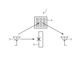
- FIG. 1 is a diagram for explaining an outline of a wireless communication system according to a first embodiment.
- FIG. 2 is a diagram showing the configuration of the radio wave control device according to the first embodiment.
- FIG. 3A is a diagram illustrating a configuration example of a polygonal housing according to a first example of the first embodiment.
- FIG. 3B is a diagram illustrating a configuration example of a polygonal housing according to the second example of the first embodiment.
- FIG. 3C is a diagram illustrating a configuration example of a polygonal housing according to the third example of the first embodiment.
- FIG. 4 is a diagram schematically showing an example of a radio wave control board.
- FIG. 5A is a diagram illustrating a configuration example of the radio wave control board according to the first embodiment.
- FIG. 5A is a diagram illustrating a configuration example of the radio wave control board according to the first embodiment.
- FIG. 5B is a diagram showing an example of the configuration of the radio wave control board according to the first embodiment.
- FIG. 5C is a diagram showing a configuration example of the radio wave control board according to the first embodiment.
- FIG. 6 is a schematic diagram showing a configuration example of a radio wave control board according to the second embodiment.
- FIG. 7 is a diagram for explaining a method of fixing the radio wave control plate according to the second embodiment to the rotary table.
- FIG. 8 is a diagram for explaining a method of rotating the rotation mechanism according to the first example of the second embodiment from outside the casing.
- FIG. 9 is a diagram illustrating a configuration example of a rotation mechanism according to a second example of the second embodiment.
- FIG. 10 is a diagram illustrating a configuration example of a rotation mechanism according to a third example of the second embodiment.
- FIG. 11 is a diagram for explaining a receivable area according to a comparative example of the third embodiment.
- FIG. 12 is a diagram for explaining a receivable area according to the third embodiment.
- FIG. 13 is a diagram for explaining a method of installing a radio wave control board according to a comparative example of the fourth embodiment.
- FIG. 14 is a diagram for explaining a method of installing a radio wave control board according to the fourth embodiment.
- FIG. 15A is a diagram illustrating a configuration example of a radio wave control board according to a first example of the fifth embodiment.
- FIG. 15A is a diagram illustrating a configuration example of a radio wave control board according to a first example of the fifth embodiment.
- FIG. 15B is a diagram illustrating a configuration example of a radio wave control board according to a second example of the fifth embodiment.
- FIG. 16 is a diagram illustrating a configuration example of a radio wave control device according to the sixth embodiment.
- FIG. 17A is a diagram for explaining the phase distribution of the first radio wave control board according to the sixth embodiment.
- FIG. 17B is a diagram for explaining the phase distribution of the second radio wave control board according to the sixth embodiment.
- FIG. 18A is a diagram illustrating an example of the phase distribution of superposition according to the sixth embodiment.
- FIG. 18B is a diagram illustrating an example of the phase distribution of superposition according to the sixth embodiment.
- FIG. 19 is a diagram for explaining a method of changing the focal position of radio waves according to the sixth embodiment.
- an XYZ orthogonal coordinate system is set, and the positional relationship of each part will be explained with reference to this XYZ orthogonal coordinate system.
- the direction parallel to the X-axis in the horizontal plane is the X-axis direction
- the direction parallel to the Y-axis in the horizontal plane perpendicular to the X-axis is the Y-axis direction
- the direction parallel to the Z-axis orthogonal to the horizontal plane is the Z-axis direction.
- a plane including the X-axis and the Y-axis is appropriately referred to as an XY plane
- a plane including the X-axis and the Z-axis is appropriately referred to as an It is called.
- the XY plane is parallel to the horizontal plane.
- the XY plane, the XZ plane, and the YZ plane are orthogonal to each other.
- FIG. 1 is a diagram for explaining an outline of a wireless communication system according to a first embodiment.
- the wireless communication system 1 includes a base station 2, a terminal 3, and a radio wave control board 4.
- the radio wave control board 4 reflects or refracts the radio waves from the base station 2, and the radio waves are transmitted to the terminal 3. receive it.
- the radio wave control board 4 is a radio wave control version in which the direction of reflection or refraction of radio waves cannot be controlled by electrical control, if the positional relationship between the terminal 3 and the radio wave control board 4 changes. , there is a possibility that communication between the base station 2 and the terminal 3 will not be established. Therefore, in the present disclosure, a radio wave control board is installed in a housing, and the radio wave control board is rotated within the housing to change the direction of reflection or refraction of radio waves.
- FIG. 2 is a diagram showing the configuration of the radio wave control device according to the first embodiment.
- the radio wave control device 10 includes a housing 12 and a radio wave control board 14.
- the radio wave control board 14 is arranged inside the housing 12.
- the radio wave control board 14 is rotatable within the XY plane inside the housing 12.
- the housing 12 is a box in which a radio control board 14 can be installed.
- the housing 12 is made of a material with a low dielectric constant that allows radio waves to pass through. It is preferable that the housing 12 is made of resin that can transmit radio waves. Examples of the resin constituting the housing 12 include, but are not limited to, ABS resin, polycarbonate resin, polyethylene resin, acrylic resin, and Teflon (registered trademark) resin.
- the housing 12 is preferably formed into a regular polygon or a circle when viewed from the Z-axis direction.
- FIG. 3A is a diagram illustrating a configuration example of a polygonal casing according to a first example of the first embodiment.
- the housing 12 according to the first example of the first embodiment has a rectangular shape when viewed from the Z-axis direction.
- the housing 12 may include a connecting portion that can be connected to another housing 12.
- the four cases 12 of the case 12-1, the case 12-2, the case 12-3, and the case 12-4 can be connected. .
- FIG. 3B is a diagram showing a configuration example of a polygonal casing according to the second example of the first embodiment.
- the housing 12A according to the second example of the first embodiment has a hexagonal shape when viewed from the Z-axis direction.
- the housing 12A may include, for example, a connecting portion that can be connected to another housing 12A.
- the four cases 12A ie, the case 12A-1, the case 12A-2, the case 12A-3, and the case 12A-4, can be connected. .
- FIG. 3C is a diagram showing a configuration example of a polygonal casing according to the third example of the first embodiment.
- the housing 12B according to the third example of the first embodiment has an octagonal shape when viewed from the Z-axis direction.
- the housing 12B may include a connecting portion that can be connected to another housing 12B.
- the four cases 12B ie, the case 12B-1, the case 12B-2, the case 12B-3, and the case 12B-4, can be connected. .
- the radio wave control board 14 is installed inside the housing 12.
- the radio wave control board 14 can be placed inside the housing 12 by opening any one surface of the housing 12, for example.
- the radio wave control board 14 is a plate-shaped member configured to allow radio waves transmitted by the base station 2 to pass through or reflect.
- the radio wave control board 14 includes a radio wave refracting plate that refracts radio waves in a predetermined direction and a radio wave reflecting plate that reflects radio waves in a predetermined direction.
- the radio wave control board 14 is configured to receive radio waves transmitted by the base station 2, refract or reflect the radio waves in the direction of the terminal, and emit the radio waves toward the terminal.
- the radio wave control board 14 may be made of, for example, a metamaterial that changes the phase of an incident wave.
- FIG. 4 is a diagram schematically showing an example of the radio wave control board 14.
- the radio wave control board 14 may include, for example, a substrate 20, an element 22, an element 24, an element 26, and an element 28.
- Element 22 , element 24 , element 26 , and element 28 may be formed on substrate 20 .
- the substrate 20 may have a rectangular shape, for example, but is not limited thereto.
- Elements 22, 24, 26, and 28 may be two-dimensionally arranged on substrate 20.
- a plurality of elements 22 may be installed in a line at the bottom of the substrate 20.
- a plurality of elements 24 may be installed in a row on a level above the level where the elements 22 are installed.
- a plurality of elements 26 may be installed in a row on a level above the level where the elements 24 are installed.
- a plurality of elements 28 may be installed in a row on a level above the level where the elements 26 are installed.
- the radio wave control board 14 may have a structure in which a plurality of elements of different sizes are arranged periodically.
- the elements 22 to 28 may differ in the amount of change in the frequency band and phase of the radio waves to be changed. Although each of the elements 22 to 28 has a rectangular shape, the shape is not limited to this. By changing the sizes and shapes of elements 22, 24, 26, and 28, it is possible to adjust the amount of change in the frequency band and phase of the radio waves to be refracted or reflected.
- the radio wave control board 14 has a rectangular shape, for example, when viewed from the Z-axis direction. It is preferable that the radio wave control board 14 has a polygonal shape when viewed from the Z-axis direction.
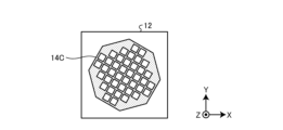
- FIG. 5A, FIG. 5B, and FIG. 5C are diagrams showing a configuration example of the radio wave control board according to the first embodiment.
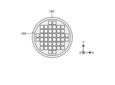
- the radio wave control board 14A is preferably configured to have a circular shape when viewed from the Z-axis direction.
- the radio wave control board 14B is preferably configured in a hexagonal shape when viewed from the Z-axis direction.
- the radio wave control board 14C is preferably configured to have an octagonal shape when viewed from the Z-axis direction.
- the radio wave control board 14 As a method for rotating the radio wave control board 14, for example, open the housing 12, take out the radio wave control board 14, and rotate the housing 12 so that it is oriented to reflect or refract radio waves in a desired direction. , it is preferable to install it inside the housing 12 again. Thereby, in the first embodiment, it is possible to easily change the reflection direction and refraction direction of radio waves whose directivity is determined at the time of design. Further, in the first embodiment, the radio wave control board 14 may be arranged at an angle with respect to the XY plane.
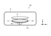
- FIG. 6 is a schematic diagram showing a configuration example of a radio wave control board according to the second embodiment.
- the radio wave control device 10A includes a housing 12, a radio wave control board 14, and a rotation mechanism 16.
- the radio wave control board 14 and the rotation mechanism 16 are arranged in the housing 12.
- the radio wave control device 10 is configured such that the radio wave control plate 14 is rotatable within the XY plane by a rotation mechanism 16.
- the rotation mechanism 16 includes a rotating table 16a and a shaft portion 16b.
- the rotary table 16a is, for example, a flat plate formed in a circular shape when viewed from the Z-axis direction.
- the shaft portion 16b is a shaft portion provided at the center of the rotary table 16a.
- the rotation mechanism 16 is a rotation mechanism in which a rotating table 16a rotates along the XY plane along the direction of the arrow around the shaft portion 16b.
- the rotation mechanism 16 is installed inside the housing 12 so that the XY plane can be rotated by a user's operation from outside the housing 12.
- the rotation mechanism 16 is installed inside the housing 12 so that, for example, the shaft portion 16b can be inserted into the bottom surface 12a of the housing 12 to rotate the XY plane.
- the radio wave control board 14 is installed on the rotating table 16a. Specifically, the radio wave control board 14 is fixed to the rotating table 16a so as not to move on the rotating mechanism 16.
- FIG. 7 is a diagram for explaining a method of fixing the radio wave control board 14D according to the second embodiment to the rotary table 16a. As shown in FIG. 7, the radio wave control board 14D has a plurality of notches 14a.
- the cutout portion 14a is a portion obtained by cutting out a portion of the periphery of the substrate of the radio wave control board 14D.
- the notch 14a can be connected to a not-illustrated protrusion formed on the rotary table 16a.
- the radio wave control plate 14D is fixed to the rotary table 16a by connecting the notch portion 14a to a protrusion (not shown) formed on the rotary table 16a.
- FIG. 8 is a diagram for explaining a method of rotating the rotation mechanism 16 from outside the housing 12 according to the first example of the second embodiment.
- FIG. 8 shows the bottom surface 12a of the casing 12 in which the rotation mechanism 16 is installed, as viewed from the outside.
- a hole 12ab is formed in the bottom surface 12a, and the shaft portion 16b of the rotation mechanism 16 installed inside the housing 12 is exposed through the hole 12ab.
- a marker M is provided around the hole 12ab.
- the marker M is provided, for example, by laser engraving.
- Marker M is an arrow indicating the rotation direction of rotation mechanism 16. The user can rotate the rotary table 16a along the XY plane by rotating the shaft portion 16b in the direction of the arrow indicated by the marker M.
- FIG. 9 is a diagram showing a configuration example of a rotation mechanism according to a second example of the second embodiment.
- the base plate of the radio wave control plate 14E is formed into a gear shape with a plurality of teeth formed on the outer periphery.
- the rotation mechanism 16A has a shaft portion 30 provided on the side surface of the casing 12 and a tooth portion 32 provided inside the casing 12.
- the shaft portion 30 and the tooth portion 32 are connected.
- the teeth 32 mesh with teeth on the outer periphery of the radio wave control board 14E.
- the rotation mechanism 16A is configured such that when the user rotates the shaft portion 30 in the direction of arrow V1, the tooth portion 32 rotates in the direction of arrow V2. Since the teeth 32 and the teeth on the outer periphery of the radio wave control plate 14E mesh with each other, when the teeth 32 rotate in the direction of arrow V2, the radio wave control plate 14E rotates in the direction of arrow V3. That is, the user can rotate the radio wave control board 14E in the direction of arrow V3 by rotating the shaft portion 30 in the direction of arrow V1.
- FIG. 10 is a diagram showing a configuration example of a rotation mechanism according to a third example of the second embodiment.
- the substrate of the radio wave control plate 14F is formed in a constant width figure shape with a plurality of teeth formed on the outer periphery and a constant width curve on the outer periphery.
- a constant width curve refers to a closed curve whose width across the line is constant, and examples include a circle and a Reuleaux polygon.
- the substrate of the radio wave control board 14F has a plurality of teeth formed on the outer periphery and is formed in a Reuleaux triangular shape.
- the substrate of the radio wave control board 14F is not limited to a Reuleaux triangle, but may be formed in a Reuleaux polygonal shape.
- the rotation mechanism 16B includes a shaft portion 30 provided on the side surface of the casing 12, a tooth portion 32 provided inside the casing 12, and a plurality of teeth provided along the inner wall of the casing 12 on the inner periphery.
- a conveyor 34 is formed.
- the teeth of the radio wave control board 14F mesh with the teeth of the conveyor 34.
- the teeth 32 mesh with the teeth of the conveyor 34.
- the rotation mechanism 16B is configured such that when the user rotates the shaft portion 30 in the direction of arrow V1, the tooth portion 32 rotates in the direction of arrow V2. Since the teeth 32 and the teeth of the conveyor 34 mesh with each other, when the teeth 32 rotate in the direction of arrow V2, the conveyor 34 moves along the inner circumference of the housing 12, as shown by arrows V5 and V6. Rotate. Since the teeth of the conveyor 34 and the teeth of the radio wave control board 14F are engaged with each other, the radio wave control board 14F rotates in the direction of the arrow V7 as the conveyor 34 rotates as shown by arrows V5 and V6. That is, the user can rotate the radio wave control board 14F in the direction of arrow V7 by rotating the shaft portion 30 in the direction of arrow V1.
- the radio wave control board installed inside the housing can be rotated from outside the housing.
- the direction of reflection and refraction of radio waves whose directivity is determined at the time of design can be easily changed.
- the beam width is defined as the beam range in which the radio waves emitted from the radio control board have half the maximum power at the distance between the radio control board and the terminal or base station.
- FIG. 11 is a diagram for explaining a receivable area according to a comparative example of the third embodiment.
- FIG. 11 schematically shows how the radio wave W1 incident on the radio wave control board 14 is refracted.
- the distance between the radio wave control board 14 and the terminal or base station is d
- the refraction angle of the radio wave is ⁇ 1
- the beam width of the radio wave W1 whose gain drops by 3 dB at a distance d from the radio wave control board 14.
- d*tan ⁇ 1 is the distance L1
- w/2*cos ⁇ 1 is the distance L2.
- the refraction angle ⁇ 1 is small with respect to the beam width w, and satisfies the condition d ⁇ tan ⁇ 1 ⁇ w/2 ⁇ cos ⁇ 1.
- the area where the radio wave W2 from the radio wave control board 14 can be received is area A1.
- Area A1 is an annular range when viewed from the Z-axis direction.
- FIG. 12 is a diagram for explaining the receivable area according to the third embodiment.
- FIG. 12 schematically shows how the radio wave W1 incident on the radio wave control board 14 is refracted.
- the distance between the radio wave control board 14 and the terminal is d
- the refraction angle of the radio wave is ⁇ 2
- the beam width of the radio wave W1 whose gain drops by 3 dB at a distance d from the radio wave control board 14 is w. do.
- d*tan ⁇ 2 be the distance L3
- w/2*cos ⁇ 2 be the distance L4.
- the refraction angle ⁇ 2 is large with respect to the beam width w, and satisfies the condition d ⁇ tan ⁇ 2 ⁇ w/2 ⁇ cos ⁇ 2.
- the area where the radio wave W2 from the radio wave control board 14 can be received is area A2.
- Area A2 is an annular range when viewed from the Z-axis direction.
- area A2 is larger. That is, when the refraction angle or reflection angle of the radio wave of the radio wave control board 14 is ⁇ , by satisfying the condition d ⁇ tan ⁇ w/2 ⁇ cos ⁇ , the receivable area can be effectively changed. .
- FIG. 13 is a diagram for explaining a method of installing a radio wave control board according to a comparative example of the fourth embodiment.
- FIG. 13 schematically shows how radio waves from the base station 50 are refracted and emitted.
- An arrow V10 indicates a direction connecting the base station 50 and the center of the radio wave control board 14.
- An arrow V11 indicates the normal direction of the radio wave control board 14.
- the radio wave control board 14 is installed such that the angle formed by the arrow V10 and the arrow V11 is an installation angle ⁇ .
- the radio wave control board 14 is configured to refract radio waves W1 from the base station and emit radio waves W2.
- the refraction angle of the radio wave W1 is ⁇ 3.
- the installation angle ⁇ is larger than the refraction angle ⁇ 3.
- step S2 the radio wave control board 14 is rotated 180 degrees. That is, the left and right sides of the radio wave control board 14 are reversed. As shown in FIG. 13, when the left and right sides of the radio wave control board 14 are reversed, the emission direction of the radio waves W2 is also reversed. Since the radio wave control board 14 is tilted with respect to the base station 50, when the emission direction of the radio wave W2 is reversed, the effective area in the refraction direction of the radio wave W1 becomes smaller, and the received power may decrease.
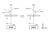
- FIG. 14 is a diagram for explaining a method of installing a radio wave control board according to the fourth embodiment.
- FIG. 14 schematically shows how radio waves from the base station 50 are refracted and emitted.
- An arrow V10 indicates a direction connecting the base station 50 and the center of the radio wave control board 14.
- An arrow V11 indicates the normal direction of the radio wave control board 14.
- the radio wave control board 14 is installed so that the arrow V10 and the arrow V11 match. That is, the installation angle, which is the angle between arrow V10 and arrow V11, is 0°. That is, in the fourth embodiment, the installation angle ⁇ is smaller than the refraction angle ⁇ 3.
- step S12 the radio wave control board 14 is rotated 180 degrees to invert the left and right sides of the radio wave control board 14. As shown in FIG. 14, when the left and right sides of the radio wave control board 14 are reversed, the emission direction of the radio waves W2 is also reversed. Since the radio wave control board 14 is not tilted with respect to the base station 50, the received power does not decrease even if the emission direction of the radio wave W2 is reversed.
- the radio wave control board 14 is configured such that the angle between the straight line connecting the base station 50 and the center of the radio wave control board 14 and the normal line of the radio wave control board 14 is smaller than the refraction angle of the radio wave control board 14. It is preferable to install it. More preferably, the angle between the straight line connecting the centers of the radio wave control board 14 and the normal line of the radio wave control board 14 is 0°. Thereby, in the fourth embodiment, it is possible to suppress a decrease in receiving sensitivity caused by rotating the radio wave control board 14.
- the received power is improved by making the surface shape of the radio wave control board a constant width curve, that is, a constant width figure.
- FIG. 15A is a diagram showing a configuration example of a radio wave control board according to the first example of the fifth embodiment.
- the radio wave control board 14A has a circular shape when viewed from the Z-axis direction.
- the shape of the radio wave control board may be a Reuleaux polygon when viewed from the Z-axis direction.
- FIG. 15B is a diagram showing a configuration example of a radio wave control board according to a second example of the fifth embodiment.
- the radio wave control plate 14G may have a Reuleaux triangle when viewed from the Z-axis direction.
- the shape of the radio wave control board is circular or a Reuleaux polygon other than a Reuleaux triangle when viewed from the Z-axis direction. Good too.
- the shape of the housing 12 when viewed from the Z-axis direction is a square with one side having a length L
- install a radio wave control board whose shape when viewed from the Z-axis direction is a square.
- the length of one side needs to be L/( ⁇ 2).
- the area of the radio wave control board is (L ⁇ 2)/2.
- the shape of the housing 12 when viewed from the Z-axis direction is a square with one side having a length L
- a radio wave control board with a circular shape when viewed from the Z-axis direction is installed.
- the length of the diameter can be set to L.
- the area of the radio wave control board is ( ⁇ /4)L ⁇ 2.
- the circular radio wave control board has a higher gain of about 2.0 dB than the square radio wave control board.
- the circular radio wave control board is 1.6 times more expensive than the square radio wave control board.
- the shape of the housing 12 as seen from the Z-axis direction is a square with one side having a length L, within a constant width curve that can be rotated inside the housing 12,
- the shape that minimizes the area of the radio wave control board is the Reuleaux triangle.
- the Reuleaux triangular radio wave control board has a higher gain of about 1.5 dB than the square radio wave control board. Converting this into received power, the Reuleaux triangular radio control board is 1.4 times more expensive than the square radio control board.
- the surface shape of the radio wave control board a constant width curve, it is possible to increase the gain of received power at a distance by 1.5 dB or more.
- FIG. 10 A sixth embodiment of the present disclosure will be described.
- a rotating radio wave control board with a constant width curve inside a housing there is a problem in that it is difficult to adjust the focal point position when it is desired to concentrate power on a specific point.
- cases in which it is desired to concentrate power at a specific point include, but are not limited to, cases in which it is desired to compensate for loss caused by a medium such as heat-reflecting glass by converging radio waves.
- the phase distribution of the radio wave control plate is configured to be concentric circles, and by making the phase distribution variable, the focal length is made variable.
- a mechanism is provided that makes the focal position variable by rotating the radio wave control plate with the center of the concentric phase distribution shifted from the rotation center.
- FIG. 16 describes a configuration example of a radio wave control device according to the sixth embodiment.
- FIG. 16 is a diagram illustrating a configuration example of a radio wave control device according to the sixth embodiment.
- FIG. 16 schematically shows a radio wave control device 10B according to the sixth embodiment.
- the radio wave control device 10B includes a housing 12, a first radio wave control board 14H-1, and a second radio wave control board 14H-2. That is, the radio wave control device 10B includes a plurality of radio wave control boards.
- the first radio wave control plate 14H-1 and the second radio wave control plate 14H-2 are arranged in an overlapping manner along the Z-axis direction.
- the radio wave control device 10B includes a rotation mechanism (not shown) that can independently rotate the first radio wave control plate 14H-1 and the radio wave control plate 14-2 within the XY plane.
- the rotation mechanism for example, the rotation mechanism 16 shown in FIG. 6, the rotation mechanism 16A shown in FIG. 9, the rotation mechanism 16B shown in FIG. 10, etc. can be used, but the invention is not limited thereto.
- the radio wave control device 10B uses the principle of a moiré lens by independently rotating two radio wave control plates, a first radio wave control plate 14H-1 and a second radio wave control plate 14H-2, within the XY plane. to change the focal length.
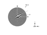
- FIG. 17A is a diagram for explaining the phase distribution of the first radio wave control board according to the sixth embodiment.
- FIG. 17B is a diagram for explaining the phase distribution of the second radio wave control board according to the sixth embodiment.
- FIG. 17A shows the phase distribution of the first radio wave control board 14H-1.
- the shade of color indicates the amount of phase change. For example, the darker the color, the larger the amount of phase change, and the lighter the color, the smaller the amount of phase change.
- the amount of phase change changes concentrically.
- FIG. 17B shows the phase distribution of the second radio wave control board 14H-2.
- the second radio wave control plate 14H-2 has, for example, the same phase distribution as the first radio wave control plate 14H-1.
- ⁇ 30° in FIG. 17B
- FIG. 18A and FIG. 18B are diagrams showing an example of the phase distribution of superposition according to the sixth embodiment.
- FIG. 18A shows a superimposed phase distribution 60 when the relative angle of the phase distribution of the second radio wave control plate 14H-2 to the phase distribution of the first radio wave control plate 14H-1 is 15°.
- FIG. 18B shows a superimposed phase distribution 62 when the relative angle of the phase distribution of the second radio wave control plate 14H-2 to the phase distribution of the first radio wave control plate 14H-1 is 30°.
- the moiré of the phase distribution changes by changing the relative angle of the phase distribution of the second radio wave control plate 14H-2 with respect to the phase distribution of the first radio wave control plate 14H-1. do. This allows the focal length to be changed.
- the focal length of the radio wave changes by changing the relative angle of the phase distribution of the second radio wave control plate 14H-2 with respect to the phase distribution of the first radio wave control plate 14H-1.
- the first radio wave control plate 14H-1 and the second radio wave control plate 14H-2 are rotated at a position different from the center of the phase distribution of the superposition of the first radio wave control plate 14H-1 and the second radio wave control plate 14H-2.
- 14H-1 and the second radio wave control board 14H-2 may be rotated as a whole.
- FIG. 19 is a diagram for explaining a method of changing the focal position of radio waves according to the sixth embodiment.
- the first radio wave control board 14H-1 and the second radio wave control board 14H-2 are arranged inside the housing 12, which has a circular shape when viewed from the Z-axis direction.
- the phase center O1 indicates the center of the phase distribution 60 of the superposition of the first radio wave control plate 14H-1 and the second radio wave control plate 14H-2.
- the rotation center O2 indicates the entire rotation center of the first radio wave control plate 14H-1 and the second radio wave control plate 14H-2 inside the housing 12.
- the focal position of the radio waves can be changed by changing the relative angle of the phase distribution of the two radio wave control plates.
- Radio control board 10A, 10B Radio control device 12, 12A, 12B, 12C Housing 14, 14A, 14B, 14C, 14D, 14E, 14F, 14G Radio control board 14H- 1 First radio control board 14H-2 Second radio control board 16, 16A, 16B Rotating mechanism
Landscapes
- Physics & Mathematics (AREA)
- Electromagnetism (AREA)
- Aerials With Secondary Devices (AREA)
Priority Applications (3)
| Application Number | Priority Date | Filing Date | Title |
|---|---|---|---|
| EP23846159.4A EP4564601A1 (en) | 2022-07-28 | 2023-07-05 | Radio wave control device and radio wave control method |
| US18/995,469 US20250350039A1 (en) | 2022-07-28 | 2023-07-05 | Radio wave control device and radio wave control method |
| JP2024536901A JP7795633B2 (ja) | 2022-07-28 | 2023-07-05 | 電波制御装置および通信システム |
Applications Claiming Priority (2)
| Application Number | Priority Date | Filing Date | Title |
|---|---|---|---|
| JP2022-120687 | 2022-07-28 | ||
| JP2022120687 | 2022-07-28 |
Publications (1)
| Publication Number | Publication Date |
|---|---|
| WO2024024426A1 true WO2024024426A1 (ja) | 2024-02-01 |
Family
ID=89706148
Family Applications (1)
| Application Number | Title | Priority Date | Filing Date |
|---|---|---|---|
| PCT/JP2023/024892 Ceased WO2024024426A1 (ja) | 2022-07-28 | 2023-07-05 | 電波制御装置および電波制御方法 |
Country Status (4)
| Country | Link |
|---|---|
| US (1) | US20250350039A1 (https=) |
| EP (1) | EP4564601A1 (https=) |
| JP (1) | JP7795633B2 (https=) |
| WO (1) | WO2024024426A1 (https=) |
Citations (3)
| Publication number | Priority date | Publication date | Assignee | Title |
|---|---|---|---|---|
| JP2015231182A (ja) | 2014-06-06 | 2015-12-21 | 日本電信電話株式会社 | メタマテリアル受動素子 |
| US20150380829A1 (en) * | 2013-02-22 | 2015-12-31 | Thales | Configurable microwave deflection system |
| WO2022091986A1 (ja) * | 2020-10-30 | 2022-05-05 | 京セラ株式会社 | 通信システム、通信方法、および電波屈折板の設置方法 |
-
2023
- 2023-07-05 US US18/995,469 patent/US20250350039A1/en active Pending
- 2023-07-05 JP JP2024536901A patent/JP7795633B2/ja active Active
- 2023-07-05 EP EP23846159.4A patent/EP4564601A1/en active Pending
- 2023-07-05 WO PCT/JP2023/024892 patent/WO2024024426A1/ja not_active Ceased
Patent Citations (3)
| Publication number | Priority date | Publication date | Assignee | Title |
|---|---|---|---|---|
| US20150380829A1 (en) * | 2013-02-22 | 2015-12-31 | Thales | Configurable microwave deflection system |
| JP2015231182A (ja) | 2014-06-06 | 2015-12-21 | 日本電信電話株式会社 | メタマテリアル受動素子 |
| WO2022091986A1 (ja) * | 2020-10-30 | 2022-05-05 | 京セラ株式会社 | 通信システム、通信方法、および電波屈折板の設置方法 |
Also Published As
| Publication number | Publication date |
|---|---|
| US20250350039A1 (en) | 2025-11-13 |
| JPWO2024024426A1 (https=) | 2024-02-01 |
| EP4564601A1 (en) | 2025-06-04 |
| JP7795633B2 (ja) | 2026-01-07 |
Similar Documents
| Publication | Publication Date | Title |
|---|---|---|
| JP4119352B2 (ja) | レンズアンテナ装置 | |
| KR101468889B1 (ko) | 이중 반사경 안테나의 부 반사경 | |
| CN1836352A (zh) | 多波束天线 | |
| US9472856B2 (en) | Antenna | |
| JP6897689B2 (ja) | 通信装置 | |
| CN110444851A (zh) | 多波束偏置馈源反射面天线 | |
| EP1291965B1 (en) | Antenna | |
| US5977923A (en) | Reconfigurable, zoomable, turnable, elliptical-beam antenna | |
| WO2024024426A1 (ja) | 電波制御装置および電波制御方法 | |
| WO2019194234A1 (ja) | 反射低減装置 | |
| US11735816B2 (en) | Gain roll-off for hybrid mechanical-lens antenna phased arrays | |
| JP6337171B1 (ja) | アンテナ装置 | |
| AU2006249603B2 (en) | Variable inclination array antenna | |
| WO2017039508A1 (en) | System, method, and apparatus for optical broadcast transmission in a circuit board | |
| US7868839B2 (en) | Planar scanner antenna for high frequency scanning and radar environments | |
| JP2024030681A (ja) | 反射装置及びシステム | |
| JPH0359602B2 (https=) | ||
| EP3345315A1 (en) | System, method, and apparatus for performing alignment between an optical transceiver and an optical reflector | |
| JP2021077982A (ja) | アンテナ装置 | |
| WO2024162166A1 (ja) | 電波反射板 | |
| JP7189062B2 (ja) | アンテナ装置および反射位相制御方法 | |
| JP2001127537A (ja) | レンズアンテナ装置 | |
| CN108155475B (zh) | 一种基于亚波长螺旋移相单元的微带反射阵列天线 | |
| WO2020066451A1 (ja) | アンテナ装置 | |
| US12355153B2 (en) | Triple-mode monopulse tracking antenna and antenna system with Risley prism beam steering |
Legal Events
| Date | Code | Title | Description |
|---|---|---|---|
| 121 | Ep: the epo has been informed by wipo that ep was designated in this application |
Ref document number: 23846159 Country of ref document: EP Kind code of ref document: A1 |
|
| WWE | Wipo information: entry into national phase |
Ref document number: 2024536901 Country of ref document: JP |
|
| WWE | Wipo information: entry into national phase |
Ref document number: 18995469 Country of ref document: US |
|
| WWE | Wipo information: entry into national phase |
Ref document number: 2023846159 Country of ref document: EP |
|
| NENP | Non-entry into the national phase |
Ref country code: DE |
|
| ENP | Entry into the national phase |
Ref document number: 2023846159 Country of ref document: EP Effective date: 20250228 |
|
| WWP | Wipo information: published in national office |
Ref document number: 2023846159 Country of ref document: EP |
|
| WWP | Wipo information: published in national office |
Ref document number: 18995469 Country of ref document: US |