WO2024019087A1 - 密封装置、密封構造、密封構造の組み付け方法 - Google Patents
密封装置、密封構造、密封構造の組み付け方法 Download PDFInfo
- Publication number
- WO2024019087A1 WO2024019087A1 PCT/JP2023/026416 JP2023026416W WO2024019087A1 WO 2024019087 A1 WO2024019087 A1 WO 2024019087A1 JP 2023026416 W JP2023026416 W JP 2023026416W WO 2024019087 A1 WO2024019087 A1 WO 2024019087A1
- Authority
- WO
- WIPO (PCT)
- Prior art keywords
- sealing device
- seal
- seal portion
- housing
- groove
- Prior art date
- Legal status (The legal status is an assumption and is not a legal conclusion. Google has not performed a legal analysis and makes no representation as to the accuracy of the status listed.)
- Ceased
Links
Images









Classifications
-
- F—MECHANICAL ENGINEERING; LIGHTING; HEATING; WEAPONS; BLASTING
- F16—ENGINEERING ELEMENTS AND UNITS; GENERAL MEASURES FOR PRODUCING AND MAINTAINING EFFECTIVE FUNCTIONING OF MACHINES OR INSTALLATIONS; THERMAL INSULATION IN GENERAL
- F16J—PISTONS; CYLINDERS; SEALINGS
- F16J15/00—Sealings
- F16J15/16—Sealings between relatively-moving surfaces
- F16J15/18—Sealings between relatively-moving surfaces with stuffing-boxes for elastic or plastic packings
- F16J15/24—Sealings between relatively-moving surfaces with stuffing-boxes for elastic or plastic packings with radially or tangentially compressed packing
-
- F—MECHANICAL ENGINEERING; LIGHTING; HEATING; WEAPONS; BLASTING
- F16—ENGINEERING ELEMENTS AND UNITS; GENERAL MEASURES FOR PRODUCING AND MAINTAINING EFFECTIVE FUNCTIONING OF MACHINES OR INSTALLATIONS; THERMAL INSULATION IN GENERAL
- F16J—PISTONS; CYLINDERS; SEALINGS
- F16J15/00—Sealings
- F16J15/02—Sealings between relatively-stationary surfaces
- F16J15/06—Sealings between relatively-stationary surfaces with solid packing compressed between sealing surfaces
- F16J15/10—Sealings between relatively-stationary surfaces with solid packing compressed between sealing surfaces with non-metallic packing
- F16J15/104—Sealings between relatively-stationary surfaces with solid packing compressed between sealing surfaces with non-metallic packing characterised by structure
-
- F—MECHANICAL ENGINEERING; LIGHTING; HEATING; WEAPONS; BLASTING
- F16—ENGINEERING ELEMENTS AND UNITS; GENERAL MEASURES FOR PRODUCING AND MAINTAINING EFFECTIVE FUNCTIONING OF MACHINES OR INSTALLATIONS; THERMAL INSULATION IN GENERAL
- F16J—PISTONS; CYLINDERS; SEALINGS
- F16J15/00—Sealings
- F16J15/16—Sealings between relatively-moving surfaces
- F16J15/32—Sealings between relatively-moving surfaces with elastic sealings, e.g. O-rings
- F16J15/3204—Sealings between relatively-moving surfaces with elastic sealings, e.g. O-rings with at least one lip
- F16J15/3232—Sealings between relatively-moving surfaces with elastic sealings, e.g. O-rings with at least one lip having two or more lips
-
- F—MECHANICAL ENGINEERING; LIGHTING; HEATING; WEAPONS; BLASTING
- F16—ENGINEERING ELEMENTS AND UNITS; GENERAL MEASURES FOR PRODUCING AND MAINTAINING EFFECTIVE FUNCTIONING OF MACHINES OR INSTALLATIONS; THERMAL INSULATION IN GENERAL
- F16J—PISTONS; CYLINDERS; SEALINGS
- F16J15/00—Sealings
- F16J15/16—Sealings between relatively-moving surfaces
- F16J15/32—Sealings between relatively-moving surfaces with elastic sealings, e.g. O-rings
- F16J15/3268—Mounting of sealing rings
- F16J15/3276—Mounting of sealing rings with additional static sealing between the sealing, or its casing or support, and the surface on which it is mounted
Definitions
- the present disclosure relates to a sealing device, a sealing structure, and a method of assembling the sealing structure.
- a rotary valve device is known as a device that switches the flow state of fluid flowing through a plurality of channels provided in one mechanical system.
- the electric vehicle thermal management system TM shown in FIG. 1 includes four circulation channels CF1, CF2, CF3, and CF4 through which coolant flows, and a multi-port valve V10 as an example of a rotary type valve device.
- the circulation flow path CF1 is provided around the battery part BT.
- the circulation channel CF2 is provided around the heat exchanger R1 and includes a pump P1.
- the circulation flow path CF3 is provided around the heat exchanger R2 and the condenser C2, and has a tank RT.
- the circulation channel CF4 is provided around the electronic component ED and the axle AX, and includes a pump P2.
- the multi-port valve V10 is provided so that the circulation channels CF1 to CF4 can merge with each other.
- Multiport valve V10 has a housing V2, a rotor V3, and a sealing device V4.
- the housing V2 has a plurality of port portions V2a connected to each of the circulation channels CF1 to CF4.
- the rotor V3 is rotatably provided inside the housing V2 around the central axis OV.
- the rotor V3 includes a plurality of port sections V3a that can be connected to the port section V2a, and a plurality of flow paths V3b that connect two port sections V3a among the plurality of port sections V3a.
- the sealing device V4 seals between the housing V2 and the rotor V3 in a state where the coolant can flow between the port portion V2a and the port portion V3a.
- the multi-port valve V10 switches the mutual connection state of the circulation channels CF1 to CF4 and the flow state of the coolant flowing through the circulation channels CF1 to CF4.
- another circulation flow path including an evaporator ER, an accumulator AR, a compressor CP, and a condenser C1 is provided around the heat exchanger R2 and the condenser C2.
- the structure of a rotary type valve device includes a valve body (i.e., a housing) having a valve chamber, and a valve body disposed inside the valve chamber, as described in Japanese Patent Application Laid-Open No. 2018-96543 (hereinafter referred to as Patent Document 1).
- a valve body i.e., a rotor
- the sealing member having a cylindrical body (i.e., a first sealing portion) and an outer rib (i.e., , a second seal portion), and a seal member having a second seal portion) are known.
- the sealing member described in Patent Document 1 has a cylindrical body and an outer rib that are integrally molded, and is made of an elastic material such as synthetic rubber.
- the outer ribs formed from a resilient material have a solid cross section.
- the outer rib generates a reaction force corresponding to a fitting force applied from the valve body toward the central axis of the cylindrical body when assembled as a valve device, and transmits the reaction force to the cylindrical body.
- the reaction force generated on the outer rib is an elastic force caused by the elastic material.
- the reaction force exerted by the outer rib acts on the cylindrical body in the same direction as the fitting force, increasing the axial force exerted by the inner periphery of the cylindrical body.
- the present disclosure aims to reduce the radial component of the reaction force transmitted from the second seal portion to the first seal portion during assembly.
- a first aspect of the present disclosure is a sealing device assembled between a cylindrical housing and a rotor that is coaxially arranged inside the housing and rotates about an axis.
- the sealing device is A first seal portion having a main body portion along an outer diameter portion of the rotor, a port portion that penetrates the main body portion in a radial direction; A groove portion formed on the outer peripheral surface of the main body portion, the groove portion having a groove bottom parallel to the outer peripheral surface, and formed to surround the port portion when viewed from the outer peripheral surface side in the radial direction.
- a groove and a first seal portion having a a second seal part that is attached to the groove part so as to be in contact with the groove bottom and seals between the housing and the first seal part, the second seal part having a bent part that can be bent during assembly;
- the seal part of has.
- a second aspect of the present disclosure is a sealing device assembled between a cylindrical housing and a rotor that is coaxially arranged inside the housing and rotates about an axis.
- the sealing device is A first seal portion having a main body portion along an outer diameter portion of the rotor, a port portion that penetrates the main body portion in a radial direction; A groove portion formed on the outer peripheral surface of the main body portion, the groove portion having a groove bottom parallel to the outer peripheral surface, and formed to surround the port portion when viewed from the outer peripheral surface side in the radial direction.
- a groove and a first seal portion having a a second seal part that is attached to the groove part so as to be in contact with the groove bottom and seals between the housing and the first seal part, the second seal part being bent in a direction intersecting the radial direction when assembled; a second seal portion having a possible bend; has.
- a third aspect of the present disclosure is a sealing device assembled between a cylindrical housing and a rotor that is coaxially arranged inside the housing and rotates around an axis.
- the sealing device is A first seal portion having a main body portion along an outer diameter portion of the rotor, a port portion that penetrates the main body portion in a radial direction; A groove portion formed on the outer peripheral surface of the main body portion, the groove portion having a groove bottom parallel to the outer peripheral surface, and formed to surround the port portion when viewed from the outer peripheral surface side in the radial direction.
- a fourth aspect of the present disclosure is a sealing device assembled between a cylindrical housing and a rotor that is coaxially arranged inside the housing and rotates about an axis.
- the sealing device is A first seal portion having a main body portion along an outer diameter portion of the rotor, a port portion that penetrates the main body portion in a radial direction; A groove portion formed on the outer peripheral surface of the main body portion, the groove portion having a groove bottom parallel to the outer peripheral surface, and formed to surround the port portion when viewed from the outer peripheral surface side in the radial direction.
- a groove and a first seal portion having a a second seal part that is attached to the groove part so as to be in contact with the groove bottom and seals between the housing and the first seal part, the second seal part being bent in a direction intersecting the radial direction when assembled; a possible second seal portion; has.
- a fifth aspect of the present disclosure is a sealed structure.
- the sealed structure is a cylindrical housing; a rotor that is coaxially arranged inside the housing and rotates about an axis; A first seal portion having a main body portion along an outer diameter portion of the rotor, a port portion that penetrates the main body portion in a radial direction; A groove portion formed on the outer peripheral surface of the main body portion, the groove portion having a groove bottom parallel to the outer peripheral surface, and formed to surround the port portion when viewed from the outer peripheral surface side in the radial direction.
- a groove and a first seal portion having a a second seal part that is attached to the groove part so as to be in contact with the groove bottom and seals between the housing and the first seal part in a bent state; has.
- a sixth aspect of the present disclosure is a sealed structure.
- the sealed structure is a cylindrical housing; a rotor that is coaxially arranged inside the housing and rotates about an axis; A first seal portion having a main body portion along an outer diameter portion of the rotor, a port portion that penetrates the main body portion in a radial direction; A groove portion formed on the outer peripheral surface of the main body portion, the groove portion having a groove bottom parallel to the outer peripheral surface, and formed to surround the port portion when viewed from the outer peripheral surface side in the radial direction.
- a groove and a first seal portion having a a second seal part that is attached to the groove part so as to be in contact with the groove bottom and seals between the housing and the first seal part in a bent state in a direction intersecting the radial direction; has.
- a seventh aspect of the present disclosure is a sealing device assembled between a cylindrical housing and a rotor that is coaxially arranged inside the housing and rotates about an axis.
- the sealing device is A first seal portion having a main body portion along an outer diameter portion of the rotor, a port portion that penetrates the main body portion in a radial direction; a groove formed in the outer circumferential surface of the main body section so as to surround the port section when viewed from the outer circumferential surface side in the radial direction, the groove section having a pair of inclined surfaces that open toward the housing side; and, a first seal portion having a a second seal part that is attached to the groove part and seals between the housing and the first seal part, the second seal part being in contact with the pair of inclined surfaces; has.
- An eighth aspect of the present disclosure is a sealing device assembled between a cylindrical housing and a rotor that is coaxially arranged inside the housing and rotates about an axis.
- the sealing device is A first seal portion having a main body portion along an outer diameter portion of the rotor, a port portion that penetrates the main body portion in a radial direction; A groove formed in the outer circumferential surface of the main body section so as to surround the port section when viewed from the outer circumferential surface side in the radial direction, the groove section being linear in a direction intersecting the radial direction when viewed in cross section.
- a groove portion having a pair of sloped surfaces that are sloped at a distance, and a groove depth; a first seal portion having a a second seal part that is attached to the groove part and seals between the housing and the first seal part, the second seal part being in contact with the pair of inclined surfaces; has The inner part of the groove forms a first gap with the second seal part, The second seal portion is deformable toward the first gap during assembly.
- Another aspect of the present disclosure is the sealing device according to any one of the first aspect to the fourth aspect, the seventh aspect, and the eighth aspect, wherein the second seal part has a hollow circular shape. It may have a cross section.
- Another aspect of the present disclosure is the sealing device according to any one of the first to fourth aspects, the seventh aspect, and the eighth aspect, wherein the second seal portion has a C-shape. It may have a cross section.
- Another aspect of the present disclosure is the sealing device according to any one of the first aspect to the fourth aspect, the seventh aspect, and the eighth aspect, wherein the second seal portion is a substantially solid circle.
- the second seal portion may have a slit-shaped opening extending from the outer periphery of the cross-section toward the center of the cross-section of the second seal portion.
- Another aspect of the present disclosure is the sealing device according to any one of the first to fourth aspects, the seventh aspect, and the eighth aspect, wherein the second seal portion is in contact with the housing.
- the housing includes an outer end portion that extends from a first direction in the axial direction relative to the first seal portion toward a second direction opposite to the first direction. It may come into contact with the outer end portion during assembly by movement.
- the radial component of the reaction force transmitted from the second seal portion to the first seal portion during assembly can be reduced.
- FIG. 1 is a schematic diagram of an electric vehicle cooling system including a rotary type valve device.
- FIG. 2 is an exploded perspective view of the sealing structure of the first embodiment.
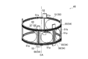
- FIG. 3 is a longitudinal cross-sectional view of the sealing structure of the first embodiment. It is a perspective view of the sealing device of a 1st embodiment.
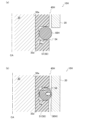
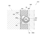
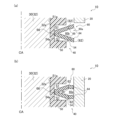
- FIG. 2 is an enlarged sectional view of the sealing device of the first embodiment. (a) is an enlarged cross-sectional view of a state in which only one open end of the second seal portion of the first embodiment is in contact with the edge of the housing. (b) is an enlarged sectional view of a state in which the other open end of the second seal portion of the first embodiment is in contact with the edge of the housing.
- FIG. 3 is an enlarged sectional view of a sealing device according to a second embodiment.
- (a) is an enlarged sectional view when the housing inserted relatively to the sealing structure starts to come into contact with the folded end of the second sealing part during assembly of the sealing structure of the second embodiment. .
- FIG. 7 is an enlarged sectional view of a sealing device according to a third embodiment. It is an enlarged sectional view of the sealing device of a 4th embodiment. It is an enlarged sectional view of the sealing device of a 5th embodiment. It is an enlarged sectional view of the sealing device of a 6th embodiment. It is an enlarged sectional view of the sealing device of a 7th embodiment.
- FIG. 7 is an enlarged cross-sectional view of a modification of the sealing device according to the present disclosure.
- FIG. 7 is an enlarged cross-sectional view of a modification of the sealing device according to the present disclosure.
- (a) is an enlarged sectional view when the second seal portion of the modified example of the sealing device according to the present disclosure is not in contact with the housing.
- (b) is an enlarged sectional view when assembly of a modified example of the sealing device according to the present disclosure is completed.
- the sealing structure 10 is a rotary valve device that switches the flow state of fluid flowing through a plurality of channels provided in one mechanical system (not shown).
- the sealing structure 10 of the first embodiment includes a housing 20, a rotor 30, and a sealing device 40, as shown in FIGS. 2 and 3.
- the housing 20 has a hollow cylindrical shape extending along the central axis CA.
- the housing 20 has a plurality of (four in this embodiment) port holes 20p on the cylindrical surface.
- the plurality of port holes 20p are formed side by side along the circumferential direction.
- Each port hole 20p penetrates the cylindrical surface in the radial direction.
- Housing 20 has an inner peripheral surface 20b.
- the housing 20 has a locking means (not shown).
- the housing 20 is engageable with a first engagement portion (not shown) provided around the sealing structure 10 in a mechanical system (not shown). By engaging the locking means with the first engagement part, the housing 20 is fixed relative to the mechanical system.
- the rotor 30 has a substantially cylindrical shape and is arranged coaxially inside the housing 20.
- the rotor 30 is rotatable around the central axis CA.
- the rotor 30 has a main body portion 32, a protrusion portion 33, and a flow path portion 34.
- the main body portion 32 has a cylindrical shape extending along the central axis CA.
- the main body portion 32 has an outer diameter portion 32a and a plurality of (in this embodiment, two) port holes 30p.
- the plurality of port holes 30p are arranged along the circumferential direction on the outer diameter portion 32a.
- the protrusion 33 has a cylindrical shape extending along the central axis CA.
- the protruding portion 33 protrudes from the end surface 32e of the main body portion 32.
- An opening 36a is formed in the end surface of the protrusion 33.
- the flow path section 34 is formed inside the rotor 30.
- the flow path portion 34 includes a first flow path 36, a plurality of second flow paths 38, and a merging portion 34a.
- the first flow path 36 extends from the opening 36a of the protrusion 33 into the main body 32 in the axial direction.
- the second flow path 38 extends in the radial direction from each of the port holes 30p of the main body 32 into the interior of the main body 32.
- the plurality of second flow paths 38 correspond to each of the plurality of port holes 30p.
- the first flow path 36 and the plurality of second flow paths 38 merge at the merge portion 34a. Note that the rotor 30 does not need to have the first flow path 36 and the opening 36a.
- the plurality of second flow paths 38 may be configured to be connected to each other.
- Each of the port holes 30p of the rotor 30 faces one of the port holes 20p of the housing 20 when the rotatable rotor 30 is in a predetermined phase. At this time, the fluid flowing through the second flow path 38 flows to the port hole 20p of the housing 20 facing the port hole 30p via a port portion 51p of the sealing device 40, which will be described later.
- the combination of the port hole 30p of the rotor 30 and the port hole 20p of the housing 20 that faces the port hole 30p changes depending on the phase of the rotor 30. That is, by changing the phase of the rotor 30 as the rotor 30 rotates, the combination of the port holes 30p and the port holes 20p changes. This switches the state of fluid flow through the mechanical system.
- the fluid flowing through the sealing structure 10 is, for example, a liquid such as oil or long life coolant (LLC).
- a liquid such as oil or long life coolant (LLC).
- the sealing device 40 is assembled between the housing 20 and the rotor 30, as shown in FIG.
- the sealing device 40 includes a first seal portion 50 and a second seal portion 60.
- the first seal portion 50 has a substantially cylindrical shape. As shown in FIG. 3, the first seal portion 50 is arranged along the outer diameter portion 32a of the rotor 30 during assembly.
- the first seal portion 50 includes a main body portion 51, a plurality of (four in this embodiment) port portions 51p, and a groove portion 54.
- the main body portion 51 has a hollow cylindrical shape extending along the central axis CA.
- the main body portion 51 has an inner circumferential surface 51a and an outer circumferential surface 51b.
- the inner circumferential surface 51a of the main body portion 51 faces the outer diameter portion 32a of the rotor 30 during assembly.
- the main body portion 51 is formed from a resin material.
- the main body portion 51 is preferably formed from a thermoplastic resin material. More preferably, the main body portion 51 is made of a fluororesin such as polytetrafluoroethylene (PTFE), ethylene-tetrafluoroethylene copolymer (ETFE), or polychlorotrifluoroethylene (PCTFE).
- the main body portion 51 may be made of an elastomer such as synthetic rubber. Note that the material forming the main body portion 51 preferably has higher rigidity than the material forming the second seal portion 60 described later. Further, it is preferable that the surface of the main body portion 51 has a lower coefficient of friction than the surface of the second seal portion 60.
- the main body portion 51 has a plurality of locking portions 52 and a plurality of locking portions 53.
- the locking portion 52 protrudes in the first axial direction from a part of the edge of the main body portion 51 in the first axial direction along the central axis CA.
- the locking portion 53 protrudes in the second axial direction from a part of the edge of the main body portion 51 in the second axial direction on the opposite side to the first axial direction.
- the plurality of locking parts 52 and 53 are arranged along the circumferential direction of the main body part 51.
- the locking parts 52, 53 are each engageable with a second engaging part (not shown) provided around the sealing structure 10 in a mechanical system (not shown).
- the main body portion 51 is fixed relative to the mechanical system by engaging the locking portions 52, 53 with the second engaging portions.
- Each port portion 51p penetrates the main body portion 51 in the radial direction.
- the plurality of port portions 51p correspond to the port holes 20p of the housing 20.
- the groove portion 54 is formed in a concave shape with respect to the outer circumferential surface 51b of the main body portion 51.
- the groove portion 54 has an annular groove 55 and a side groove 56.
- the annular groove 55 and the side groove 56 are formed to surround each of the plurality of port portions 51p when viewed from the outer peripheral surface 51b side in the radial direction.
- the annular groove 55 circumferentially surrounds the outer circumferential surface 51b.
- a pair of annular grooves 55 sandwich the plurality of port portions 51p in the axial direction of the main body portion 51.
- the side groove 56 spans between the pair of annular grooves 55.
- the plurality of side grooves 56 sandwich each of the plurality of port portions 51p in the circumferential direction of the main body portion 51.
- the groove bottoms of the annular groove 55 and the side grooves 56 are along a cylindrical surface parallel to the outer circumferential surface 51b. That is, as shown in FIG. 5, the groove portion 54 has a groove bottom 54a that is parallel to the outer circumferential surface 51b. Further, the groove portion 54 has a groove wall 54b extending from the groove bottom 54a to the outer peripheral surface 51b.
- the first seal portion 50 has a function of sealing between the inner peripheral surface 51a of the first seal portion 50 and the outer diameter portion 32a of the rotor 30. Note that the sealing function of the first seal portion 50 prevents foreign matter from entering from outside of the region where the inner circumferential surface 51a of the first seal portion 50 and the outer diameter portion 32a of the rotor 30 face each other. It is preferable to act so as to suppress. The sealing function of the first seal portion 50 may not act to seal fluid flowing through the sealing structure 10.
- the second seal part 60 is arranged along the groove part 54 of the first seal part 50, as shown in FIG.
- the second seal portion 60 is separate from the first seal portion 50.
- the second seal portion 60 has an annular portion 67 and a bridging portion 68.
- the annular portion 67 corresponds to the pair of annular grooves 55 of the groove portion 54 .
- the bridging portion 68 corresponds to the side groove 56 of the groove portion 54.
- the bridging portion 68 spans between the pair of annular portions 67 .
- the second seal portion 60 has a function of sealing between the first seal portion 50 and the housing 20.
- the second seal portion 60 is made of elastomer such as synthetic rubber.
- the second seal portion 60 is preferably formed of ethylene propylene diene rubber (EDPM).
- the second seal portion 60 is made of an elastomer base material having a predetermined cross-sectional shape. Specifically, the second seal portion 60 has a shape in which the base material is continuously extended in a direction intersecting the cross section of the base material. That is, each of the annular portions 67 has a shape in which the cross section of the base material is continuously extended in an annular shape. Each of the bridging parts 68 has a shape in which the cross section of the base material is continuously extended along the central axis CA, with the direction intersecting the cross section of the base material being aligned with the central axis CA of the first sealing part 50. have
- the second seal portion 60 has a V-shaped cross section, as shown in FIG.
- the V-shaped cross section of the second seal portion 60 has a thickness.
- the second seal portion 60 is open toward the housing 20 side. That is, the second seal portion 60 has an opening 60a.
- the opening 60a opens toward the housing 20 side.
- the second seal portion 60 has two open ends 64 and a folded end 66 in cross-sectional view. Further, the second seal portion 60 has a bent portion 62 .
- the opening 60a extends continuously along the direction in which the cross section of the second seal portion 60 extends. That is, the opening 60a is along the direction in which the second seal portion 60 extends.
- the opening 60a is formed in a concave shape with respect to the outer periphery of the second seal portion 60 when viewed in cross section.
- the open end 64 is the open end of the opening 60a in cross-sectional view.
- the two open ends 64 of the annular portion 67 are aligned with each other along the axial direction of the first seal portion 50 .
- the two open ends 64 of the bridge portion 68 are aligned with each other along the circumferential direction of the first seal portion 50 .
- the folded end 66 is an end that is folded back into a V-shape in cross-sectional view.
- the second seal portion 60 is attached to the first seal portion 50 so that the folded end 66 is in contact with the groove bottom 54a.
- a gap S1 is formed between the second seal portion 60 and the groove wall 54b.
- a gap S1 is formed between the bent portion 62 of the second seal portion 60 and the groove portion 54.
- the second seal part 60 attached to the groove part 54 has an open end 64 projecting in the radial direction from the outer circumferential surface 51b of the first seal part 50.
- the second seal part 60 attached to the groove part 54 comes into contact with the housing 20 so that the open end 64 can fit into the inner circumferential surface 20b of the housing 20 during assembly.
- the open end 64 is an example of an outer end.
- the second seal part 60 seals between the first seal part 50 and the housing 20 by being pressed toward the groove bottom 54a by the housing 20.
- the second seal portion 60 surrounds the port portion 51p of the first seal portion 50 with the annular portion 67 and the bridging portion 68 when viewed from the radial direction.
- the annular portion 67 suppresses leakage of the fluid flowing between the port portion 51p of the first seal portion 50 and the port hole 20p of the housing 20 in the axial direction.
- the bridging portion 68 suppresses fluid leakage between adjacent port portions 51p or port holes 20p.
- the axial force applied from the first seal part 50 to the rotor 30 increases as the housing 20 presses the second seal part 60 against the groove bottom 54a.
- the bent portion 62 is a portion of the second seal portion 60 that extends from the two open ends 64 toward the folded end 66 .
- the bent portion 62 is configured to include the open end 64.
- the bent portion 62 is bent in a direction intersecting the radial direction of the first seal portion 50 when assembled with the housing 20 . That is, the bent portion 62 can be bent in a direction intersecting the radial direction of the first seal portion 50 during assembly.
- the second seal portion 60 can be bent in a direction intersecting the radial direction of the first seal portion 50 during assembly.
- the second seal portion 60 has a space 60b sandwiched between two open ends 64. The space 60b is adjacent to the bent portion 62 in cross-sectional view.
- the space 60b is located closer to the center of the cross section than the bent portion 62 when viewed in cross section.
- the bending of the bent portion 62 is preferably accompanied by elastic deformation in the axial direction.
- the bending of the bend 62 may be accompanied by volumetric compression of the elastomer.
- the first seal portion 50 is assembled to the rotor 30.
- the second seal part 60 is attached to the groove part 54 of the first seal part 50 assembled to the rotor 30.
- the sealing device 40 is assembled to the rotor 30.
- the housing 20 is assembled by moving the housing 20 toward the sealing device 40 from the outside in the axial direction (see FIG. 6). That is, the sealing device 40 is assembled by moving relatively from the outside to the inside of the housing 20 in the axial direction.
- the first open end 64 which is the side closer to the housing 20, comes into contact with the edge of the housing 20.
- a moment directed in the moving direction of the housing 20 is applied to the bent portion 62 including the first open end 64 in a cross-sectional view.
- a fitting force is applied to the second seal part 60 attached to the groove part 54 so that it is pressed from the housing 20 toward the groove bottom 54a.
- the bent portion 62 including the first open end 64 is bent in a direction intersecting the radial direction of the first seal portion 50.
- the bent portion 62 including the first open end 64 is bent so as to close the opening 60a.
- sealing structure 10H as a comparison form with respect to the first embodiment will be described using FIG. 7.
- the reference numerals and names of the parts will be used as they are.
- the comparative sealing structure 10H has a sealing device 40H instead of the sealing device 40 in the first embodiment.
- the sealing device 40H has a second seal portion 60H instead of the second seal portion 60, as shown in FIG.
- the second seal portion 60H has a solid circular cross section, as shown in FIG. 7(a). That is, the second seal portion 60H of the comparative embodiment does not have the opening 60a, the bent portion 62, and the open end 64. Further, the second seal portion 60H of the comparative embodiment does not have a structure that can be bent during assembly.
- the protrusion length of the second seal part 60H attached to the first seal part 50 from the outer circumferential surface 51b in the radial direction is the same as the protrusion length of the second seal part 60 of the first embodiment.
- the comparative sealing structure 10H has the same configuration as the sealing structure 10.
- the second seal portion 60H of the comparative embodiment attached to the groove portion 54 is elastically deformed so as to be compressed by the fitting force directed from the housing 20 toward the groove bottom 54a during assembly.
- the second seal part 60H attached to the first seal part 50 generates a reaction force according to the fitting force.
- the reaction force generated in the second seal portion 60H is an elastic force caused by the elastomer.
- the reaction force (elastic force) by the second seal portion 60H is transmitted to the first seal portion 50 in the radial direction toward the center axis CA, which is the same as the fitting force.
- the sealing device 40 has a bending portion 62 that can be bent in a direction intersecting the radial direction of the first sealing portion 50 when assembled. That is, the sealing device 40 has a second seal portion 60 that can be bent in a direction intersecting the radial direction of the first seal portion 50 when assembled.
- the reaction force (elastic force) generated in the second seal portion 60H in response to the fitting force from the housing 20 when the sealing structure 10 is assembled is smaller than that of the comparative sealing structure 10H (see FIG. 8). Therefore, by having the second seal part 60, the sealing device 40 reduces the radial component of the reaction force (elastic force) transmitted from the second seal part 60 to the first seal part 50 during assembly. be able to.
- the sealing structure 10 having the sealing device 40, the radial component of the reaction force (elastic force) transmitted from the second seal part 60 to the first seal part 50 becomes small, so that the first seal part 50 and the rotor 30 is smaller than that of the sealing structure 10H. Therefore, the sealing structure 10 can improve the assemblability of the sealing structure 10. In addition, the sealing structure 10 can improve the slidability of the rotor 30 by reducing the frictional force between the first seal portion 50 and the rotor 30. That is, when the sealing structure 10 is assembled by assembling the housing 20 after assembling the sealing device 40 to the rotor 30, it is possible to suppress deterioration of the slidability of the rotor 30 due to the assembling.
- the sealing structure 10 having the sealing device 40, the reaction force (elastic force) generated in the second seal part 60H in response to the fitting force from the housing 20 becomes small, so that the second seal part 60H and the housing 20 The frictional force between the sealing structure 10H and the sealing structure 10H is smaller than that of the sealing structure 10H. Therefore, the sealing structure 10 can further improve the assemblability of the sealing structure 10. That is, when the sealing structure 10 is assembled by assembling the housing 20 after assembling the sealing device 40 to the rotor 30, the ease of assembling the housing 20 can be improved.
- the bent portion 62 includes an open end 64 that contacts the housing 20 during assembly. Therefore, the bending portion 62 can be bent by a moment applied as a result of relative movement of the housing 20 from the outside to the inside in the axial direction during assembly. Therefore, the sealing device 40 can bend the second seal portion 60 more easily by further applying a fitting force from the housing 20 during assembly.
- the second seal portion 60 of the sealing device 40 has an opening 60a.
- the section modulus of the second seal part 60 becomes smaller, so the second seal part 60 becomes easier to bend. Therefore, when the sealing device 40 is assembled, the second seal portion 60 is easily bent.
- the bent portion 62 of the sealing device 40 can be bent to close the opening 60a during assembly.
- a sealing device A40 shown in FIG. 17 The sealing device A40 has a second sealing portion A60 instead of the second sealing portion 60 of the sealing device 40, as shown in FIG. 17(a).
- the second seal portion A60 has a V-shaped cross section that opens in the axial direction of the first seal portion 50.
- the second seal portion A60 has an opening A60a and an open end A64.
- the open end A64 on the housing 20 side comes into contact with the housing 20.
- the open end A64 on the housing 20 side is deformed along the moving direction of the housing 20, as shown in FIG. 17(b).
- the second seal portion A60 deforms so as to widen the opening portion A60a. If the second seal portion A60 is deformed to enlarge the opening A60a when the housing 20 is assembled, there is a possibility that the second seal portion A60 may turn over to the opening A60a side.
- the sealing device 40 can suppress the second seal portion 60 from turning over during assembly.
- the second seal portion 60 of the sealing device 40 has a V-shaped cross section. At this time, the second seal portion 60 is easily bent at a portion extending from the open end 64 to the folded end 66. Therefore, it is easy to identify the portion of the sealing device 40 that is bent during assembly.
- the opening 60a of the second seal portion 60 opens toward the housing 20 side. That is, in the second seal portion 60, the two open ends 64 are in contact with the housing 20. If the opening of the second seal portion having a V-shaped cross section opens toward the rotor 30 side, the second seal portion contacts the housing 20 at one folded end.
- the sealing performance between the second seal part and the housing 20 improves as the number of contact points between the second seal part and the housing 20 increases. Therefore, the sealing device 40 can improve the sealing performance between the second seal portion 60 and the housing 20 compared to the case where the opening is open toward the rotor 30 side.
- the second seal portion 60 of the sealing device 40 has open ends 64 that are aligned with each other along the axial direction.
- the frictional force between one open end and the housing 20 may be greater than the frictional force between the other open end and the housing 20 depending on the size of the misalignment. Since the size of the sealing device also increases, the ease of assembling the sealing device becomes difficult.
- the two open ends 64 are lined up along the axial direction, the deviation in the radial position of the two open ends is small. Therefore, the difference in frictional force between each open end 64 and the housing 20 that occurs when the sealing device 40 is assembled becomes small. Therefore, the sealing device 40 can improve ease of assembly compared to a case where the two open ends 64 are misaligned in the radial direction.
- a gap S1 is formed between the groove portion 54 and the bent portion 62 of the sealing device 40. Therefore, when the bent portion 62 is bent in a cross-sectional view, it can be bent toward the gap S1. Therefore, the sealing device 40 can bend the second seal portion 60 toward the gap S1 during assembly.
- the second seal portion 60 is adjacent to the bent portion 62 in cross-sectional view, and has a space 60b provided closer to the center of the cross-section than the bent portion 62. Therefore, when the bent portion 62 is bent in a cross-sectional view, it can be bent toward the space 60b. Therefore, the sealing device 40 can bend the second seal portion 60 toward the space 60b during assembly.
- the sealing structure 10 may be assembled by assembling the sealing device 40 to the housing 20 and then assembling the rotor 30 to the inner peripheral surface 51a of the sealing device 40.
- the radial component of the reaction force (elastic force) transmitted from the second seal part 60 to the first seal part 50 is small, the radial direction component of the reaction force (elastic force) transmitted from the second seal part 60 to the first seal part 50 is small.
- the increase in force is smaller than that of the comparative sealing structure 10H. That is, in this case, the frictional force between the first seal portion 50 and the rotor 30 that occurs when the first seal portion 50 is assembled with the rotor 30 is smaller than that of the comparative sealing structure 10H. Therefore, when the sealing structure 10 is assembled by assembling the sealing device 40 to the housing 20 and then assembling the rotor 30 to the inner peripheral surface 51a of the sealing device 40, it is possible to improve the ease of assembling the rotor 30.
- the sealing structure 210 has a sealing device 240 instead of the sealing device 40 in the first embodiment, as shown in FIG. 9 .
- the sealing device 240 has a second seal portion 260 instead of the second seal portion 60 in the first embodiment.
- the second seal portion 260 has a V-shaped cross section, as shown in FIG.
- the V-shaped cross section of the second seal portion 260 has a thickness.
- the cross section of the second seal portion 260 is open toward the rotor 30 side. That is, the second seal portion 260 has an opening 260a.
- the opening 260a opens toward the rotor 30 side.
- the second seal portion 260 has two open ends 264 and a folded end 266 in cross-sectional view. Further, the second seal portion 260 has a bent portion 262 .
- the second seal part 260 is attached to the first seal part 50 so that the two open ends 264 are in contact with the groove bottom 54a of the groove part 54. At this time, a gap S2 is formed between the second seal portion 260 and the groove wall 54b. In other words, a gap S2 is formed between the bent portion 262 and the groove portion 54.
- the second seal portion 260 mounted in the groove portion 54 brings the folded end 266 into contact with the housing 20 .
- the folded end 266 is an example of an outer end.
- the bent portion 262 includes a folded end 266.
- the second seal portion 260 has a space 260b sandwiched between two open ends 264.
- the space 260b is adjacent to the bent portion 262 in cross-sectional view.
- the space 260b is located closer to the center of the cross section than the bent portion 262 when viewed in cross section.
- the first seal portion 50 is assembled to the rotor 30.
- the second seal part 260 is attached to the groove part 54 of the first seal part 50 assembled to the rotor 30. That is, the sealing device 240 is assembled to the rotor 30.
- the housing 20 is assembled by moving the housing 20 relative to the sealing device 240 from the outside in the axial direction toward the sealing device 240 (see FIG. 10).
- the folded end 266 first comes into contact with the edge of the housing 20.
- a moment directed in the moving direction of the housing 20 is applied to the bent portion 262 including the folded end 266 in a cross-sectional view.
- a fitting force from the housing 20 toward the groove bottom 54a is applied to the second seal part 260 attached to the groove part 54.
- the first bent portion 262 which is on the housing 20 side with respect to the second seal portion 260 in the axial direction, is in a bent state.
- the sealing structure 210 has the same configuration as the sealing structure 10.
- the opening 260a of the second seal portion 260 opens toward the rotor 30 side. That is, in the second seal portion 260, one folded end 266 contacts the housing 20. Therefore, the frictional force generated between the second seal portion 260 and the housing 20 during assembly is smaller than that in the case where the opening is open toward the housing 20 side. Therefore, the sealing device 240 can improve ease of assembly compared to a case where the opening opens toward the housing 20 side.
- the sealing structure 310 has a sealing device 340 instead of the sealing device 40 in the first embodiment, as shown in FIG. 11 .
- the sealing device 340 has a second seal portion 360 instead of the second seal portion 60 in the first embodiment.
- the second seal portion 360 has a hollow annular cross section, as shown in FIG. 11 .
- the annular cross section of the second seal portion 360 has a thickness.
- the second seal portion 360 has an outer edge. Further, the second seal portion 360 has a bent portion 362 . Note that the second seal portion 360 does not have an opening in cross-sectional view.
- the second seal portion 360 has a space 360b inside its annular cross section.
- the space 360b is adjacent to the bent portion 362 in cross-sectional view.
- the space 360b is located closer to the center of the cross section than the bent portion 362 when viewed in cross section.
- the sealing structure 310 has the same configuration as the sealing structure 10.
- the sealing structure 310 and the sealing device 340 have the same effects as the sealing structure 10 and the sealing device 40, except for the effect due to the opening.
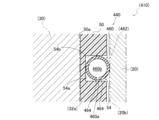
- the sealing structure 410 has a sealing device 440 instead of the sealing device 40 in the first embodiment, as shown in FIG. 12 .
- the sealing device 440 has a second seal portion 460 instead of the second seal portion 60 in the first embodiment.
- the second seal portion 460 has a C-shaped cross section, as shown in FIG. 12 .
- the C-shaped cross section of the second seal portion 460 has a thickness.
- the second seal portion 460 has an opening 460a.
- the opening 460a opens toward the groove wall 54b in cross-sectional view.
- the second seal portion 460 has two open ends 464 in cross-sectional view.
- the second seal portion 460 has a bent portion 462.
- the second seal portion 460 has an outer edge.
- the second seal portion 460 has a space 460b inside the C-shaped cross section.
- the space 460b is adjacent to the bent portion 462 in cross-sectional view.
- the space 460b is located closer to the center of the cross section than the bent portion 462 when viewed in cross section.
- the sealing structure 410 has the same configuration as the sealing structure 10.
- the sealing structure 410 and the sealing device 440 have the same effects as the sealing structure 210 and the sealing device 240.
- the sealing structure 510 has a sealing device 540 instead of the sealing device 40 in the first embodiment, as shown in FIG. 13 .
- the sealing device 540 has a second seal portion 560 instead of the second seal portion 60 in the first embodiment.
- the second seal portion 560 has a substantially solid circular cross section, as shown in FIG.
- the second seal portion 560 has an opening 560a formed in a concave shape with respect to the outer periphery of the second seal portion 560 when viewed in cross section.
- the opening 560a is formed in a slit shape extending from the outer periphery of the cross section of the second seal portion 560 toward the center of the cross section.
- the opening 560a opens toward the groove wall 54b in cross-sectional view.
- the second seal portion 560 has two open ends 564 in cross-sectional view. Further, the second seal portion 560 has a bent portion 562.
- the bent portion 562 includes a portion where the distance between the inner part of the opening 560a and the outer circumference of the second seal portion 560 is the shortest in cross-sectional view.
- the second seal portion 560 has an outer edge. Except for the above points, the sealing structure 510 has the same configuration as the sealing structure 10.
- the sealing structure 510 and the sealing device 540 have the same effect as the sealing structure 210 and the sealing device 240.
- the sealing structure 610 has a sealing device 640 instead of the sealing device 40 in the first embodiment, as shown in FIG. 14 .
- the sealing device 640 has a first sealing portion 650 and a second sealing portion 660.
- the first seal portion 650 has a groove portion 654 instead of the groove portion 54 in the first embodiment.
- the groove portion 654 is formed in a V-shape when viewed in cross section.
- the groove portion 654 has a rear end portion 654a and a pair of inclined surfaces 654b.
- the rear end portion 654a is an end portion that is bent in a V-shape when viewed in cross section.
- the pair of inclined surfaces 654b are open toward the housing 20 side.
- Each inclined surface 654b is inclined linearly in a direction intersecting the radial direction when viewed in cross section.
- the pair of inclined surfaces 654b have symmetry in the radial direction of the first seal portion 650.
- the second seal portion 660 has a substantially solid circular cross section, as shown in FIG. That is, the second seal portion 660 does not have an opening, a bent portion, and an open end. Further, the second seal portion 660 does not have a structure that can be bent during assembly.
- the second seal portion 660 is attached to the first seal portion 650 while contacting the pair of inclined surfaces 654b of the groove portion 654.
- a gap S6 is formed between the second seal portion 660 and the inner end portion 654a.
- the sealing structure 610 has the same configuration as the sealing structure 10.
- the second seal part 660 attached to the first seal part 650 generates a reaction force (elastic force) according to the fitting force applied from the housing 20 during assembly.
- the second seal portion 660 comes into contact with the pair of inclined surfaces 654b. Therefore, the reaction force (elastic force) generated in the second seal portion 660 is directed toward the first seal via the groove portion 654 in a direction opposite to the normal direction of each of the pair of inclined surfaces 654b. 650.
- the radial component of the reaction force (elastic force) transmitted from the second seal part 660 to the first seal part 650 when the seal structure 610 is assembled becomes smaller than that of the comparative seal structure 10H. Therefore, by having the groove portion 654, the sealing device 640 can reduce the radial component of the reaction force (elastic force) transmitted from the second seal portion 660 to the first seal portion 650 during assembly.
- sealing structure 610 including the sealing device 640 can have the same effects as the sealing structure 10.
- a gap S6 is formed between the rear end portion 654a and the second seal portion 660 when not assembled.
- the second seal part 660 exhibits behavior peculiar to the elastomer so as to make the area of the gap S6 smaller than when it is not pressed by the housing 20. Transform towards S6. That is, the second seal portion 660 can be deformed toward the gap S6 during assembly.
- the sealing device 640 can reduce the reaction force (elastic force) generated in the second seal portion 60 due to the pressing from the housing 20 during assembly.
- the pair of inclined surfaces 654b have symmetry in the radial direction of the first seal portion 650. At this time, the forces generated between the pair of inclined surfaces 654b and the second seal portion 660 during assembly cancel each other out in the axial direction. Therefore, the second seal portion 660 is difficult to shift from the groove portion 654 in the axial direction during assembly. Therefore, the sealing device 640 can improve ease of assembly.
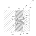
- the sealing structure 710 has a sealing device 740 instead of the sealing device 40 in the first embodiment, as shown in FIG. 15 .
- the sealing device 740 has a first seal portion 750 instead of the first seal portion 50 in the first embodiment.
- the sealing device 740 includes the second seal portion 60 in the first embodiment. That is, the second seal portion 60 of the sealing device 740 has a bent portion 62 that can be bent during assembly. Additionally, the second seal portion 60 of the sealing device 740 has a folded end 66 .
- the sealing device 740 may have any of the second seal parts 260, 360, 460, and 560 instead of the second seal part 60.
- the first seal portion 750 has a groove portion 754 instead of the groove portion 54 in the first embodiment.
- the groove 754 is similar to the groove 654 in the sixth embodiment. That is, as shown in FIG. 15, the groove portion 754 is formed in a V-shape when viewed in cross section.
- the groove portion 754 has a rear end portion 754a and a pair of inclined surfaces 754b.
- the pair of inclined surfaces 754b are open toward the housing 20 side.
- Each inclined surface 754b is inclined linearly in a direction intersecting the radial direction in cross-sectional view.
- the pair of inclined surfaces 754b have symmetry in the radial direction of the first seal portion 750.
- the second seal portion 60 is attached to the first seal portion 750 while contacting the pair of inclined surfaces 754b of the groove portion 754.
- the second seal part 60 is attached to the first seal part 750 so that the folded end 66 contacts the pair of inclined surfaces 754b. At this time, a gap S7 is formed between the bent portion 62 and the pair of inclined surfaces 754b.
- the sealing structure 610 has the same configuration as the sealing structure 10.
- the second seal portion 60 of the sealing device 740 has a bent portion 62 that can be bent during assembly. Therefore, the sealing device 740 can further reduce the amount of deformation of the first seal portion 750 during assembly.
- a gap S7 is formed between the groove portion 754 of the sealing device 740 and the bent portion 62. Therefore, the bent portion 62 can be bent toward the gap S7. Therefore, in the sealing device 740, when the second seal part 60 is attached to the groove part 754 having the pair of inclined surfaces 754b, the second seal part 60 cannot be bent toward the gap S7 during assembly. can.
- the opening of the second seal may extend in the radial or axial direction of the first seal.
- the opening was made in the direction along the line.
- the opening of the second seal part according to the present disclosure may be opened in a direction inclined with respect to the radial direction and/or the axial direction of the first seal part.
- the groove portions 654 and 754 in the sixth embodiment and the seventh embodiment are formed in a V-shape in cross-sectional view.
- the groove portion having a pair of inclined surfaces according to the present disclosure further includes a groove bottom sandwiched between the pair of inclined surfaces and parallel to the outer circumferential surface of the first seal portion. Good too.
- the first seal portion 50 of the first embodiment extends from the cylindrical outer peripheral surface 51b to the groove wall 54b.
- the first seal portion 50 may have a protrusion 57 around the groove portion 54, as shown in FIG. 16.
- the protrusion 57 is formed in a rib shape along the groove portion 54. That is, the first seal portion according to the present disclosure may have a rib-shaped protrusion around the groove portion.
- the second seal portion 60 of the first embodiment is bent so as to close the opening 60a.
- the second seal portion of the sealing device according to the present disclosure may be bent to open the opening.
- the sealing device according to the present disclosure may be, for example, the sealing device A40 described above (see FIG. 17).
- the second seal portion according to the present disclosure may be a second seal portion 860 having a spiral cross-sectional shape, as shown in FIG. 18 .
- the second seal portion 860 has a buckling portion 862, a space 860a, and an opening 860b.
- the second seal portion 60 of the first embodiment may be configured such that the open end 64 is bent toward the space 60b, as shown in FIG. 19(b). Specifically, as shown in FIG.
- the second seal portion 60 has a cut 69 in a part of the space 60b side extending from the folded end 66 to the open end 64 in a cross-sectional view. may have.
- the second seal portion 60 may have a crease instead of the cut 69. It is preferable that the cut 69 or the fold line extends along the direction in which the cross section of the second seal portion 60 extends. The cut 69 or the fold may extend linearly so as to intersect with the direction in which the cross section of the second seal portion 60 extends.
- CA Central axis 10: Sealing structure 20: Housing 20b: Inner circumferential surface 30: Rotor 40: Sealing device 50: First seal portion 51: Main body portion 51p: Port portion 51b: Outer circumferential surface 51a: Inner circumferential surface 54: Groove portion 54a : Groove bottom 60 : Second seal part 60a : Opening part 62 : Bent part 64 : Open end S1 : Gap 210 : Sealing structure 240 : Sealing device 260 : Second seal part 260a : Opening part 262 : Bent part 264 : Open end S2 : Gap 310 : Sealing structure 340 : Sealing device 360 : Second seal part 362 : Bent part 410 : Sealing structure 440 : Sealing device 460 : Second seal part 460a : Opening part 462 : Bent part 464 : Open end 510: Sealing structure 540: Sealing device 560: Second seal portion 560a: Opening portion 562: Bent portion 564:
Landscapes
- Engineering & Computer Science (AREA)
- General Engineering & Computer Science (AREA)
- Mechanical Engineering (AREA)
- Sealing Devices (AREA)
- Gasket Seals (AREA)
- Sealing With Elastic Sealing Lips (AREA)
Priority Applications (6)
| Application Number | Priority Date | Filing Date | Title |
|---|---|---|---|
| US18/880,784 US20260002589A1 (en) | 2022-07-21 | 2023-07-19 | Sealing device, sealing structure, and sealing structure assembly method |
| JP2024535113A JP7727854B2 (ja) | 2022-07-21 | 2023-07-19 | 密封装置、密封構造、密封構造の組み付け方法 |
| CN202380052845.2A CN119546888A (zh) | 2022-07-21 | 2023-07-19 | 密封装置、密封结构、密封结构的组装方法 |
| KR1020257000226A KR20250019736A (ko) | 2022-07-21 | 2023-07-19 | 밀봉 장치, 밀봉 구조, 밀봉 구조의 설치 방법 |
| DE112023003158.4T DE112023003158T5 (de) | 2022-07-21 | 2023-07-19 | Dichtungsvorrichtung, Dichtungsstruktur und Montageverfahren für Dichtungsstruktur |
| JP2025133077A JP2025160497A (ja) | 2022-07-21 | 2025-08-08 | 密封装置、密封構造、密封構造の組み付け方法 |
Applications Claiming Priority (2)
| Application Number | Priority Date | Filing Date | Title |
|---|---|---|---|
| JP2022116173 | 2022-07-21 | ||
| JP2022-116173 | 2022-07-21 |
Publications (1)
| Publication Number | Publication Date |
|---|---|
| WO2024019087A1 true WO2024019087A1 (ja) | 2024-01-25 |
Family
ID=89617815
Family Applications (1)
| Application Number | Title | Priority Date | Filing Date |
|---|---|---|---|
| PCT/JP2023/026416 Ceased WO2024019087A1 (ja) | 2022-07-21 | 2023-07-19 | 密封装置、密封構造、密封構造の組み付け方法 |
Country Status (6)
| Country | Link |
|---|---|
| US (1) | US20260002589A1 (https=) |
| JP (2) | JP7727854B2 (https=) |
| KR (1) | KR20250019736A (https=) |
| CN (1) | CN119546888A (https=) |
| DE (1) | DE112023003158T5 (https=) |
| WO (1) | WO2024019087A1 (https=) |
Citations (4)
| Publication number | Priority date | Publication date | Assignee | Title |
|---|---|---|---|---|
| JPH04111903U (ja) * | 1991-03-14 | 1992-09-29 | 株式会社フジユニバンス | 油圧式サーボ機構のシール装置 |
| US5676348A (en) * | 1996-06-12 | 1997-10-14 | Fmc Corporation | Asymmetric seal segment configuration |
| US20080142752A1 (en) * | 2006-12-14 | 2008-06-19 | S.P.M. Flow Control, Inc. | Plug valve having a seal boss |
| CN112728153A (zh) * | 2021-01-05 | 2021-04-30 | 中国船舶重工集团公司第七0七研究所九江分部 | 一种旋塞阀自补偿式软密封结构 |
Family Cites Families (1)
| Publication number | Priority date | Publication date | Assignee | Title |
|---|---|---|---|---|
| JP6577066B2 (ja) | 2018-01-16 | 2019-09-18 | 株式会社不二工機 | 流路切換弁 |
-
2023
- 2023-07-19 JP JP2024535113A patent/JP7727854B2/ja active Active
- 2023-07-19 US US18/880,784 patent/US20260002589A1/en active Pending
- 2023-07-19 KR KR1020257000226A patent/KR20250019736A/ko active Pending
- 2023-07-19 WO PCT/JP2023/026416 patent/WO2024019087A1/ja not_active Ceased
- 2023-07-19 CN CN202380052845.2A patent/CN119546888A/zh active Pending
- 2023-07-19 DE DE112023003158.4T patent/DE112023003158T5/de active Pending
-
2025
- 2025-08-08 JP JP2025133077A patent/JP2025160497A/ja active Pending
Patent Citations (4)
| Publication number | Priority date | Publication date | Assignee | Title |
|---|---|---|---|---|
| JPH04111903U (ja) * | 1991-03-14 | 1992-09-29 | 株式会社フジユニバンス | 油圧式サーボ機構のシール装置 |
| US5676348A (en) * | 1996-06-12 | 1997-10-14 | Fmc Corporation | Asymmetric seal segment configuration |
| US20080142752A1 (en) * | 2006-12-14 | 2008-06-19 | S.P.M. Flow Control, Inc. | Plug valve having a seal boss |
| CN112728153A (zh) * | 2021-01-05 | 2021-04-30 | 中国船舶重工集团公司第七0七研究所九江分部 | 一种旋塞阀自补偿式软密封结构 |
Also Published As
| Publication number | Publication date |
|---|---|
| JPWO2024019087A1 (https=) | 2024-01-25 |
| CN119546888A (zh) | 2025-02-28 |
| JP2025160497A (ja) | 2025-10-22 |
| US20260002589A1 (en) | 2026-01-01 |
| KR20250019736A (ko) | 2025-02-10 |
| JP7727854B2 (ja) | 2025-08-21 |
| DE112023003158T5 (de) | 2025-06-05 |
Similar Documents
| Publication | Publication Date | Title |
|---|---|---|
| US6565096B2 (en) | Lip type seal | |
| WO2022151760A1 (zh) | 一种控制阀 | |
| US6422570B2 (en) | Lip type seal | |
| JP6913186B2 (ja) | シールリング | |
| WO2019139005A1 (ja) | 偏心型バタフライバルブ | |
| JP2020046077A (ja) | シールリング | |
| JP4898799B2 (ja) | 独立したシーリングリップを有するシャフトシール | |
| JP7846229B2 (ja) | 密封装置、密封構造、密封構造の組み付け方法 | |
| JP7727854B2 (ja) | 密封装置、密封構造、密封構造の組み付け方法 | |
| WO2008013281A1 (en) | Seal ring | |
| KR102659110B1 (ko) | 스포크 로터리 시일 | |
| WO2014030506A1 (ja) | シールリング | |
| JP6872671B2 (ja) | シールリング | |
| JP3804257B2 (ja) | 密封装置 | |
| JP4670272B2 (ja) | シールリング | |
| JPS6342234Y2 (https=) | ||
| JP7724012B2 (ja) | ロータリバルブ | |
| TWI876610B (zh) | 滾珠螺桿 | |
| JP7695362B2 (ja) | 密封装置 | |
| JP2007177923A (ja) | 継手用ブーツ | |
| WO2017195882A1 (ja) | シールリング | |
| JPH09144889A (ja) | 密封装置 | |
| WO2024157877A1 (ja) | 密封装置 | |
| JP2022152163A (ja) | 流体封入式筒型防振装置 | |
| JP2007092791A (ja) | シールリング |
Legal Events
| Date | Code | Title | Description |
|---|---|---|---|
| 121 | Ep: the epo has been informed by wipo that ep was designated in this application |
Ref document number: 23843010 Country of ref document: EP Kind code of ref document: A1 |
|
| WWE | Wipo information: entry into national phase |
Ref document number: 18880784 Country of ref document: US |
|
| ENP | Entry into the national phase |
Ref document number: 20257000226 Country of ref document: KR Kind code of ref document: A |
|
| WWE | Wipo information: entry into national phase |
Ref document number: 1020257000226 Country of ref document: KR |
|
| WWE | Wipo information: entry into national phase |
Ref document number: 202380052845.2 Country of ref document: CN |
|
| WWE | Wipo information: entry into national phase |
Ref document number: 2024535113 Country of ref document: JP |
|
| WWP | Wipo information: published in national office |
Ref document number: 1020257000226 Country of ref document: KR |
|
| WWE | Wipo information: entry into national phase |
Ref document number: 112023003158 Country of ref document: DE |
|
| WWP | Wipo information: published in national office |
Ref document number: 202380052845.2 Country of ref document: CN |
|
| WWP | Wipo information: published in national office |
Ref document number: 112023003158 Country of ref document: DE |
|
| 122 | Ep: pct application non-entry in european phase |
Ref document number: 23843010 Country of ref document: EP Kind code of ref document: A1 |
|
| WWP | Wipo information: published in national office |
Ref document number: 18880784 Country of ref document: US |