WO2024014335A1 - 異常判定装置、レーザ加工機、及び異常判定方法 - Google Patents
異常判定装置、レーザ加工機、及び異常判定方法 Download PDFInfo
- Publication number
- WO2024014335A1 WO2024014335A1 PCT/JP2023/024579 JP2023024579W WO2024014335A1 WO 2024014335 A1 WO2024014335 A1 WO 2024014335A1 JP 2023024579 W JP2023024579 W JP 2023024579W WO 2024014335 A1 WO2024014335 A1 WO 2024014335A1
- Authority
- WO
- WIPO (PCT)
- Prior art keywords
- unit
- workpiece
- processing
- state quantity
- movement
- Prior art date
- Legal status (The legal status is an assumption and is not a legal conclusion. Google has not performed a legal analysis and makes no representation as to the accuracy of the status listed.)
- Ceased
Links
Images








Classifications
-
- B—PERFORMING OPERATIONS; TRANSPORTING
- B23—MACHINE TOOLS; METAL-WORKING NOT OTHERWISE PROVIDED FOR
- B23K—SOLDERING OR UNSOLDERING; WELDING; CLADDING OR PLATING BY SOLDERING OR WELDING; CUTTING BY APPLYING HEAT LOCALLY, e.g. FLAME CUTTING; WORKING BY LASER BEAM
- B23K26/00—Working by laser beam, e.g. welding, cutting or boring
-
- B—PERFORMING OPERATIONS; TRANSPORTING
- B23—MACHINE TOOLS; METAL-WORKING NOT OTHERWISE PROVIDED FOR
- B23K—SOLDERING OR UNSOLDERING; WELDING; CLADDING OR PLATING BY SOLDERING OR WELDING; CUTTING BY APPLYING HEAT LOCALLY, e.g. FLAME CUTTING; WORKING BY LASER BEAM
- B23K26/00—Working by laser beam, e.g. welding, cutting or boring
- B23K26/02—Positioning or observing the workpiece, e.g. with respect to the point of impact; Aligning, aiming or focusing the laser beam
- B23K26/03—Observing, e.g. monitoring, the workpiece
-
- B—PERFORMING OPERATIONS; TRANSPORTING
- B23—MACHINE TOOLS; METAL-WORKING NOT OTHERWISE PROVIDED FOR
- B23K—SOLDERING OR UNSOLDERING; WELDING; CLADDING OR PLATING BY SOLDERING OR WELDING; CUTTING BY APPLYING HEAT LOCALLY, e.g. FLAME CUTTING; WORKING BY LASER BEAM
- B23K26/00—Working by laser beam, e.g. welding, cutting or boring
- B23K26/08—Devices involving relative movement between laser beam and workpiece
-
- B—PERFORMING OPERATIONS; TRANSPORTING
- B23—MACHINE TOOLS; METAL-WORKING NOT OTHERWISE PROVIDED FOR
- B23K—SOLDERING OR UNSOLDERING; WELDING; CLADDING OR PLATING BY SOLDERING OR WELDING; CUTTING BY APPLYING HEAT LOCALLY, e.g. FLAME CUTTING; WORKING BY LASER BEAM
- B23K31/00—Processes relevant to this subclass, specially adapted for particular articles or purposes, but not covered by any single one of main groups B23K1/00 - B23K28/00
Definitions
- the present invention relates to an abnormality determination device, a laser processing machine, and an abnormality determination method.
- a laser processing machine performs laser processing such as cutting on a workpiece by irradiating the workpiece with laser light while moving a laser head relative to the workpiece.
- Laser processing machines are required to appropriately perform laser processing on a workpiece. Therefore, in laser processing, if good processing quality is obtained in test processing or actual processing, the operator performs a prescribed operation to memorize the laser output amount reference value, and then performs laser processing based on this value. It has been proposed to perform (for example, see Patent Document 1).
- a sensor In a processing device such as a laser processing machine, in order to manage processing quality, a sensor is sometimes installed to detect a state quantity related to processing of a workpiece by the processing device.
- the state quantity detected by the sensor is used to determine whether or not there is a machining abnormality on the workpiece based on whether or not the state quantity is out of a preset normal state quantity range (hereinafter referred to as "normal range").
- This normal range may be set wide (relaxed) depending on the operating conditions of the processing device. When the normal range is widened, a situation may occur in which a state that should originally be determined to be abnormal is not determined to be abnormal. Therefore, from the viewpoint of improving the accuracy of determining processing abnormalities, it is desired to obtain a more appropriate normal range.
- laser processing is only performed based on the laser output amount reference value, and the above-described problems cannot be solved.
- An object of the present invention is to provide an abnormality determination device, a laser processing machine, and an abnormality determination method that can accurately determine processing abnormalities on a workpiece.
- An abnormality determination device includes a moving section that moves relative to a workpiece, and a processing section that is provided in the moving section and that processes the workpiece while moving relative to the workpiece together with the moving section.
- An abnormality determination device for determining a machining abnormality of the workpiece in a machining device comprising: an abnormality determining device that is provided in the moving section, and is configured to move with the moving portion relative to the workpiece while causing the machining device to process the workpiece; a sensor unit that detects a related state quantity; an acquisition unit that acquires a movement relationship value regarding the movement of the moving unit; a storage unit that stores the state quantity detected by the sensor unit in association with the movement-related value acquired by the acquisition unit when performing normal processing; a calculation unit that calculates a normal range of the state quantity for each of the movement related values based on the calculation unit; and a calculation unit that calculates the normal range of the state quantity for each of the movement related values; and a determination unit that determines whether the abnormality determining device that is provided
- a laser processing machine includes a laser head that moves with respect to a workpiece, and a laser beam that is provided on the laser head and that emits a laser beam onto the workpiece while moving with the laser head with respect to the workpiece. It includes a laser emitting unit that processes a workpiece, and an abnormality determination device that determines a processing abnormality of the workpiece.
- the abnormality determination device includes a sensor unit that is provided in the laser head and detects a state quantity of the laser processing machine while moving with the laser head relative to the workpiece, and acquires a movement relationship value regarding the movement of the laser head.
- the state quantity detected by the sensor unit when the laser emitting unit moves relative to the workpiece as the laser head moves and performs normal processing on the workpiece a storage unit that stores the movement-related value in association with the movement-related value acquired by the acquisition unit; and a calculation unit that calculates the normal range of the state quantity for each movement-related value based on the information accumulated in the storage unit. , after the normal range is calculated, whether the state quantity detected by the sensor section is within the normal range when the laser head moves relative to the work and processes the work. and a determination unit that determines whether or not the determination is made based on a calculation result by the calculation unit.
- An abnormality determination method includes a moving part that moves relative to a workpiece, and a processing part provided in the moving part that processes the workpiece while moving with the moving part relative to the workpiece.
- a method for determining abnormality in machining of the workpiece in a machining device having the following steps: , detecting a state quantity of the processing device by a sensor unit that moves with respect to the workpiece together with the moving unit; acquiring a movement relationship value regarding the movement of the moving unit by an acquisition unit; and detecting by the sensor unit. accumulating the state quantity in association with the movement-related value acquired by the acquisition unit in an accumulation unit; and calculating a normal range of the state quantity based on the information accumulated in the accumulation unit.
- the method further includes determining whether the state quantity detected by the sensor unit is within the normal range based on a calculation result by the calculation unit.
- the abnormality determination device, laser processing machine, and abnormality determination method set the normal range in consideration of the movement-related value regarding the movement of the moving part, so that it is possible to accurately determine a processing abnormality on the workpiece.
- the movement related value may include the movement speed of the moving part.
- the movement relationship value may include the movement direction of the movement part.
- the moving part may be a laser head included in a laser processing machine, and the processing part may be a laser emitting part of the laser head that emits laser light.
- the calculation unit calculates a table indicating a normal range for each movement-related value based on the information accumulated in the storage unit, and the determination unit calculates the state quantity detected by the sensor unit. It may be determined based on a table whether or not the value is within a normal range. Further, the calculation unit derives an arithmetic expression for calculating the normal range for each movement-related value based on the information accumulated in the storage unit, and the determination unit determines that the state quantity detected by the sensor unit is within the normal range. It may be determined whether or not it is based on an arithmetic expression.
- the sensor unit may detect at least one of the amount of light, temperature, sound, and image analysis result as the state quantity.
- processing abnormalities can be detected from at least one of the analysis results of light intensity, temperature, sound, and images.
- the laser processing machine of the above aspect may include a head control device that stops processing the workpiece when the determination unit determines that the state quantity detected by the sensor unit is outside the normal range.
- the laser head controller may include a head control device that changes the moving speed of the head.
- FIG. 1 is a diagram illustrating an example of a laser processing machine and an abnormality determination device according to an embodiment. It is a figure showing an example of composition of a laser head.
- FIG. 3 is a diagram showing an example of a functional section of an abnormality determination section.
- FIG. 3 is a diagram showing a first example of a table.
- FIG. 3 is a diagram showing a first example of a table. It is a figure which shows the 2nd example of a table. It is a figure which shows the 2nd example of a table. It is a figure which shows the 2nd example of a table.
- FIG. 3 is a diagram showing a method of dividing a speed setting range.
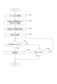
- FIG. 3 is a flow diagram of an abnormality determination method according to an embodiment. It is a figure which shows the 1st example of a test processing shape. This is a second example of a test processed shape. It is a figure which shows the problem of abnormality determination in the laser processing machine based on a comparative example.
- FIG. 7 is a diagram showing the relationship between the state quantity obtained in laser processing according to a comparative example, the moving speed, and the moving direction, respectively.
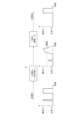
- FIG. 3 is a diagram showing a transfer function.
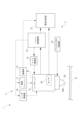
- FIG. 1 is a diagram showing an example of a laser processing machine 1 and an abnormality determination device 3 according to an embodiment.
- FIG. 2 is a diagram showing an example of the configuration of the laser head 12 provided in the laser processing machine 1 of FIG. 1.
- the laser processing machine 1 according to the present embodiment is an apparatus that emits a laser beam L to perform laser processing such as cutting and marking on a workpiece W to be processed.
- the laser processing machine 1 includes a processing device 2 and an abnormality determination device 3.
- the processing device 2 includes a laser oscillator 10, an illumination unit 11, a laser head 12, an imaging section 13, a head drive section 14, a head control device 15, and an assist gas supply section 16.
- the laser oscillator 10 generates a processing laser beam L1.
- the processing laser is an infrared laser beam.
- the laser oscillator 10 is connected to a laser head 12 via an optical fiber F.
- the optical fiber F introduces the processing laser beam L1 output from the laser oscillator 10 into the laser head 12.
- the illumination unit 11 includes a laser array 11A and a collimator 11B.
- the laser array 11A emits illumination laser light L2 having a different wavelength from the processing laser light L1.
- the collimator 11B is provided at a position where the illumination laser beam L2 from the laser array 11A is incident, and converts the illumination laser beam L2 incident from the laser array 11A into parallel light.
- the laser head 12 irradiates the work W with laser light L (processing laser light L1 and illumination laser light L2) from the nozzle 20.
- the laser head 12 is provided so as to be movable relative to the workpiece W in the X direction, the Y direction, and the Z direction.
- the laser head 12 performs cutting by irradiating a processing laser beam L1 along a cutting line formed on the workpiece W while moving relative to the workpiece W. Note that the laser head 12 is an example of a "moving section.”
- the laser head 12 includes a nozzle 20, a collimator 21, a beam splitter 22, a condenser lens 23, a half mirror 24, a wavelength selection filter 25, and an imaging lens 26.
- the nozzle 20 is attached below the laser head 12 (-Z side). Nozzle 20 is directed downward.
- the nozzle 20 has an emission hole 20A.
- the processing laser light L1 and the illumination laser light L2 are irradiated downward from the emission hole 20A.
- the nozzle 20 is connected to the assist gas supply section 16 via a gas supply pipe or the like.
- the nozzle 20 supplies the assist gas from the assist gas supply section 16 to the workpiece W toward a region to be irradiated with the processing laser beam L1.
- the nozzle 20 is an example of a processing section and corresponds to a laser emitting section.
- the configuration of the illumination unit 11, imaging unit 13, beam splitter 22, half mirror 24, wavelength selection filter 25, imaging lens 26, etc. is based on the mode in which the sensor 30 detects light intensity, temperature, sound, etc. (image analysis results). (aspects in which state quantities other than the above are detected) do not necessarily need to be provided.
- the collimator 21 is provided so that the focal point on the incident side of the processing laser beam L1 coincides with the position of the end of the optical fiber F, and converts the processing laser beam L1 output from the laser oscillator 10 into parallel light.
- the beam splitter 22 is provided at a position where the processing laser light L1 that has passed through the collimator 21 is incident, and the condenser lens 23 that transmits the processing laser light L1 and reflects the illumination laser light L2 is provided from the beam splitter 22. It is provided at a position where the processing laser beam L1 enters, and condenses the incident processing laser beam L1.
- the condensing lens 23 is movable along the optical axis by an optical system drive unit (not shown). The focus on the workpiece W side is adjusted by this optical system drive section.
- the half mirror 24 is provided at a position where the illumination laser light L2 that has passed through the collimator 11B is incident, and reflects part of the illumination laser light L2 and allows part of it to pass through.
- the illumination laser beam L2 reflected by the half mirror 24 is reflected by the beam splitter 22.
- the condensing lens 23 condenses the illumination laser beam L2 reflected from the beam splitter 22.
- the area of the workpiece W that is irradiated with the illumination laser beam L2 is set to include the area of the workpiece W that is irradiated with the processing laser beam L1.
- the return light from the workpiece W passes through the condenser lens 23 and enters the beam splitter 22.
- the returned light includes light that is the illumination laser beam L2 reflected and confused by the work W, and light that is the processing laser beam L1 that is reflected by the work W.
- Light originating from the illumination laser beam L2 is reflected by the beam splitter 22 and enters the half mirror 24.
- the light originating from the processing laser beam L1 is reflected by the beam splitter 22 and enters the half mirror 24.
- the returned light includes light emitted from the molten metal in a wavelength range from infrared to near-infrared. Light originating from the molten metal is reflected by the beam splitter 22 and enters the half mirror 24 .
- the wavelength selection filter 25 is, for example, a dichroic mirror, a notch filter, or the like.
- the returned light that has entered the half mirror 24 passes through the half mirror 24 and enters the wavelength selection filter 25 .
- Light originating from the illumination laser beam L2 is reflected by the wavelength selection filter 25 and enters the imaging lens 26.
- the light originating from the processing laser beam L1 passes through the wavelength selection filter 25.
- the imaging lens 26 focuses the light reflected by the wavelength selection filter 25 onto the imaging section 13 .
- the imaging unit 13 is provided in the laser head 12.
- the imaging unit 13 is a device that images an area irradiated with the processing laser beam L1.
- the imaging unit 13 includes an imaging element 13A.
- the image sensor 13A is an image sensor that detects return light generated by the illumination of the illumination laser light L2 reflected and confused by the workpiece W, and generates image data.
- the imaging unit 13 transmits image data generated by the imaging device 13A to the head control device 15.
- the head drive section 14 is controlled by the head control device 15 and moves the laser head 12 in each of the X direction, Y direction, and Z direction.
- the head drive unit 14 includes, for example, a gantry that is movable in the X direction, a slider that is movable in the Y direction with respect to the gantry, and an elevating unit that is movable in the Z direction with respect to the slider. Note that the head drive unit 14 is not limited to the above configuration, and may be realized by other configurations such as a robot arm.
- the head control device 15 controls the movement of the laser head 12 by controlling the head drive section 14. For example, the head control device 15 acquires position information of the laser head 12 at a predetermined period, and controls movement of the laser head 12 by controlling the head drive unit 14 based on the acquired position information. Further, the head control device 15 obtains a movement relationship value, which is a value related to movement of the laser head 12, based on the position information of the laser head 12. The movement related value is, for example, the moving speed and/or moving direction of the laser head 12. Note that the moving direction is the processing direction of laser processing. The head control device 15 controls the head drive unit 14 so that the obtained movement relationship value becomes a preset setting value. Further, the head control device 15 outputs the obtained movement relationship value to the abnormality determination device 3.
- the assist gas supply section 16 is connected to the laser head 12.
- the assist gas supply section 16 is a device that supplies assist gas into the nozzle 20.
- Assist gas is used in laser processing to remove molten material.
- As the assist gas supply source for example, a gas cylinder, a factory supply line, etc. are used.
- As the assist gas for example, nitrogen gas, air, a mixed gas of nitrogen and oxygen, etc. are used.
- the abnormality determination device 3 may include an image processing unit (not shown) that generates data regarding the processing state based on the image data generated by the image sensor 13A.
- the image processing unit may generate data indicating the kerf width as data related to the machining state, or may generate numerical information indicating the combustion state such as the behavior of molten metal in the workpiece W. , or both.
- the data regarding the processing state may be an example of the above-mentioned image analysis results.
- the abnormality determination device 3 determines whether there is a processing abnormality in the workpiece W in the processing device 2 .
- the abnormality determination device 3 includes a sensor 30 and an abnormality determination section 31.
- the sensor 30 is provided in the laser head 12.
- the sensor 30 is, for example, provided integrally with the laser head 12 and is configured to similarly move as the laser head 12 moves.
- the sensor 30 may be provided inside the laser head 12.
- the sensor 30 detects a state quantity X related to processing of the workpiece W by the processing device 2 while moving with respect to the workpiece W together with the laser head 12 as the laser head 12 moves.
- the state quantity X is one or more data for the abnormality determination unit 31 to determine whether the processing device 2 is normal or abnormal, and is a value that directly or indirectly indicates the state of the processing device 2.
- the sensor 30 is an example of the "sensor section" of the present invention.
- the "sensor section" of the present invention detects at least one of the amount of light, temperature, sound, and image analysis result as the state quantity X.
- the "sensor section" of the present invention may include one or more of the sensors listed below. That is, the state quantity X may be a sensor value detected by one or more sensors listed below.
- a temperature sensor that detects heat generated by the condenser lens 23 for converging and diffusing laser light.
- a light amount sensor that detects the amount of reflected light of the processing laser beam L1.
- a sound sensor that detects sounds around the laser head 12.
- An image sensor that monitors the size of the cutting groove and the behavior of the molten metal based on images near the processing point.
- the above-mentioned sensor part is the sensor illustrated in the above (a), the above (b), or the above (c), the above sensor part corresponds to the sensor 30.
- the illumination unit 11, the imaging section 13, and the image processing section are not essential components for implementing the present invention.
- the above-mentioned sensor section is the above-mentioned sensor (d)
- the above-mentioned sensor section corresponds to the illumination unit 11, the imaging section 13, and the above-mentioned image processing section.
- the sensor 30 illustrated in FIG. 1 is not an essential configuration for implementing the present invention.
- the abnormality determination device 3 uses the illumination unit 11, the imaging section 13, and the above-mentioned image processing section as the sensor section, for example. Be prepared.
- the above image processing section may be included in the abnormality determination section 31 or may be a device other than the abnormality determination section 31.
- the device other than the abnormality determination section 31 may be, for example, the imaging section 13.
- the case where the above-mentioned sensor section is the sensor 30 will be described as an example.
- the abnormality determination unit 31 is, for example, an information processing device such as a computer.
- the abnormality determination section 31 is connected to the head control device 15 and can exchange information with each other.
- the abnormality determination section 31 is connected to the sensor 30.
- the abnormality determination unit 31 determines whether there is a processing abnormality in the workpiece W in the processing apparatus 2 based on the state quantity X detected by the sensor 30.
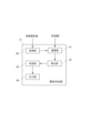
- FIG. 3 is a diagram illustrating an example of the functional units of the abnormality determination unit 31.
- the abnormality determination section 31 includes an acquisition section 40, a storage section 41, a calculation section 42, a determination section 43, and an output section 44.
- these components are realized by, for example, a hardware processor such as a CPU (Central Processing Unit) executing a program (software).
- a hardware processor such as a CPU (Central Processing Unit) executing a program (software).
- some or all of these components may be implemented using hardware such as LSI (Large Scale Integrated Circuit), ASIC (Application Specific Integrated Circuit), FPGA (Field-Programmable Gate Array), or GPU (Graphics Processing Unit). It may be realized by a circuit unit (including circuitry), or it may be realized by cooperation of software and hardware.
- the program may be stored in advance in a storage device (a storage device equipped with a non-transitory storage medium) such as an HDD (Hard Disk Drive) or flash memory, or may be stored in a removable storage device such as a DVD or CD-ROM. It may be stored in a medium (non-transitory storage medium), and installed in the storage device by loading the storage medium into a drive device.
- a storage device includes, for example, an HDD, a flash memory, an EEPROM (Electrically Erasable Programmable Read Only Memory), a ROM (Read Only Memory), or a RAM (Random Access Memory).
- the acquisition unit 40 acquires movement relationship values regarding the movement of the laser head 12. For example, the acquisition unit 40 acquires the movement relationship value from the head control device 15.
- the acquisition unit 40 may have a communication interface for communicating with the head control device 15, for example.
- the storage unit 41 is detected by the sensor 30 when normal laser processing (hereinafter referred to as "test processing") is performed on the workpiece W by irradiating laser light from the nozzle while the laser head 12 is moving.
- the state quantity X is stored in association with the movement relationship value acquired by the acquisition unit 40.
- the storage unit 41 stores the state quantity X detected by the sensor 30 in association with the movement relationship value acquired by the acquisition unit 40 at regular intervals.
- the abnormality determination part 31 may further be equipped with the above-mentioned image processing part as a functional part. In this case, the storage unit 41 acquires the image analysis result as the state quantity X from the image processing unit.
- Test machining is laser machining in a state where no machining abnormality has occurred on the test work W (hereinafter referred to as "test work").
- the machining conditions for test machining are adjusted in advance so that laser machining can be performed without degrading the quality of the workpiece due to excessive combustion or poor cutting.
- the operator determines whether or not the workpiece W has been properly laser-machined based on the actual machining state and machining properties of the workpiece.
- the storage unit 41 stores test data of information in which the state quantity X and the movement relationship value during normal laser processing are associated with each other. Note that the state quantity X detected by the sensor 30 during test machining may be referred to as "state quantity X1" for the purpose of distinguishing it from others.
- the calculation unit 42 determines the normal range (hereinafter referred to as “normal range”) is calculated for each movement-related value. For example, the calculation unit 42 creates a table 100 that directly or indirectly defines the normal range of the state quantity X for each movement-related value based on the test data accumulated in the accumulation unit 41. Note that the calculation unit 42 may create the table 100 for each workpiece W (such as the material and plate thickness of the workpiece W), or may create the table 100 for each processing condition for processing the workpiece W. It may be both.
- the processing conditions are, for example, the output of the processing laser beam L1, the focal position of the processing laser beam L1 with respect to the workpiece, and the pressure of the assist gas.
- the table 100 is a table (hereinafter referred to as a "normal range table") that directly defines the normal range of the state quantity It may be composed of.
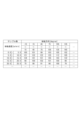
- FIG. 4 is a diagram showing a first example of the normal range table according to the present embodiment.
- the normal range table shown in FIG. 4 includes a minimum value table (FIG. 4A) and a maximum value table (FIG. 4B).
- the minimum value table shows the minimum value of the normal range of the state quantity This is a table defined in a matrix.
- the maximum value table is a table in which the maximum values of the normal range of the state quantity X are defined in a matrix for each speed setting range and direction setting range.
- FIG. 5 is a diagram showing a second example of the table 100.
- the table 100 may be a table that indirectly defines the normal range of the state quantity X for each moving speed and moving direction in a matrix form.
- the table 100 is a table (hereinafter referred to as "normal (referred to as “range calculation table”), and may be composed of one or more tables.
- the normal range calculation table shown in FIG. 5 the average value, standard deviation, and number of samples are used as statistical information. More specifically, the normal range calculation table shown in FIG. 5 includes an average value table (FIG. 5A), a standard deviation table (FIG. 5B), and a sample number table (FIG. 5C).
- the average value table is a table in which average values of the state quantity X1 are defined in a matrix for each speed setting range and direction setting range.
- the standard deviation table is a table in which standard deviations of the state quantity X1 are defined in a matrix for each speed setting range and direction setting range.
- the sample number table is a table in which the number of samples of the state quantity X1 is determined in a matrix for each speed setting range and direction setting range.
- the number of samples of the state quantity X1 is the number of state quantities X1 used to create the average value table or the standard deviation table.
- the statistical information for calculating the normal range is not limited to the average value, standard deviation, and number of samples, and may include other statistical information such as kurtosis and skewness.
- FIG. 6 is a diagram showing a method of dividing the speed setting range.
- the width of each speed setting range may or may not all be the same width; for example, the width of each speed setting range may be set exponentially so that the width of the speed setting range becomes wider as the speed increases. may be done. That is, as a division method when dividing the normal range table into a matrix for each movement speed and movement direction, it may be divided by linearly dividing it into equal parts as shown in FIG. As shown in B), the speed setting range may be divided into an exponential function so that the higher the speed, the wider the range.
- the method of linearly dividing the speed setting range into equal parts has a simple configuration, and is useful when it is desired to reliably link the normal range to the moving speed when the speed is stable, such as at low speeds.
- the method of dividing the speed setting range exponentially makes it possible to stabilize the abnormality determination criteria because the parameters referenced on the table are unlikely to change even when the movement speed changes greatly in a high-speed region. That is, the method of dividing the speed setting range exponentially is useful when there are large changes in moving speed in a high-speed region.
- FIG. 6(B) the same table parameters are referenced for the speed setting range of 21 to 33 m/min.
- FIG. 6A it is necessary to refer to three table parameters for the speed setting range of 21 to 33 m/min.
- the determination unit 43 determines the state quantity detected by the sensor 30 when the laser head 12 moves to perform actual laser processing (hereinafter referred to as "actual processing") on the workpiece W that is not for testing.
- actual processing actual laser processing
- the presence or absence of an abnormality is determined as to whether or not X is within the normal range based on the table 100 which is an example of the calculation results of the calculation unit 42. Actual processing is performed after the table 100 is calculated.
- the determination unit 43 acquires the state quantity X detected by the sensor 30 and the movement related value of the laser head 12 at regular intervals.
- the state quantity X during actual processing may be referred to as the "state quantity X2."
- the determination unit 43 acquires the normal range associated with the movement relationship value during actual machining from the normal range table. Then, the determining unit 43 determines whether the state quantity X2 is within the read normal range or not at regular intervals.
- the determination unit 43 determines that there is a machining abnormality when the state quantity X2 is outside the normal range. For example, the determination unit 43 determines that there is a machining abnormality when the state quantity X2 falls outside the normal range even once.
- the present invention is not limited to this form, and if the number of times the state quantity It may be determined that there is an abnormality. Note that the number of times it has been determined that there is an abnormality may be the number of times that the state quantity X has continuously fallen outside the normal range during the most recent predetermined period. Note that the above specified number of times may be changeable depending on the workpiece W to be processed and the processing conditions.
- the calculation unit 42 acquires the state quantity X2 detected by the sensor 30 and the movement-related value during the actual machining at regular intervals during the actual machining. do. Then, the calculation unit 42 acquires the average value and standard deviation associated with the movement-related values during actual processing, and creates a normal range based on the acquired average value and standard deviation.
- FIG. 7 is a diagram illustrating a method for determining the normal range of the state quantity X from the normal range calculation table.
- the calculation unit 42 calculates the range between the upper limit value shown in equation (1) and the lower limit value shown in equation (2) based on the average value and standard deviation acquired from the normal range calculation table. may be calculated as the normal range.
- the calculation unit 42 is not limited to this form, and may calculate a range below the upper limit shown in equation (1) as a normal range (FIG. 7B), or a range above the lower limit shown in equation (2).
- the range may be calculated as a normal range (FIG. 7C).
- the determination unit 43 determines whether the state quantity X2 is within the normal range using a method similar to the abnormality determination described above.
- the gain ⁇ 1 and the gain ⁇ 2 may each have the same value or may have different values. In the example shown in FIG. 7, ⁇ 1 and ⁇ 2 are both “3”. Note that ⁇ 1 and ⁇ 2 may be set based on kurtosis and skewness, respectively.
- the determination unit 43 does not have to perform abnormality determination of the state quantity X2 in that cycle.
- processing may be performed to adjust the gains, such as increasing each value of gain ⁇ 1 and gain ⁇ 2 from “3” to “4” in abnormality determination in that period.
- the output unit 44 outputs the determination result of the determination unit 43.
- the output unit 44 may output the determination result only when the determination unit 43 determines that there is a processing abnormality.
- the output unit 44 may display the determination result of the determination unit 43 on the display device (not shown) by outputting the determination result of the determination unit 43 to the display device (not shown).
- the present invention is not limited to this form, and the output unit 44 may output the determination result of the determination unit 43 to a communication terminal used by a user via a wired or wireless communication network. Further, the determination result of the determination unit 43 may be used for feedback control (reducing the moving speed, etc.) to the machining conditions.
- the output unit 44 may output a signal indicating the determination result to the head control device 15.
- the head control device 15 acquires a signal indicating the determination result of the determining section 43, it may perform feedback control to change the moving speed until the moving speed falls within the normal range.
- FIG. 8 is a flow diagram of the abnormality determination method according to this embodiment.
- the laser processing machine 1 first starts test processing (step S101).
- the abnormality determination device 3 stores the state quantity X detected by the sensor 30 in association with the movement related value of the laser head 12 during the test machining (step S102).
- the abnormality determination device 3 calculates the normal range of the state quantity X for each movement-related value based on the information accumulated in the accumulation section (step S103).
- the laser processing machine 1 laser-processes the test workpiece into a preset shape (hereinafter referred to as "test processing shape").
- the test machining shape is a shape that can ensure a sufficient number of samples for the moving speed and moving direction that frequently appear in the shape to be machined in actual machining.
- FIG. 9 is a first example of a test processed shape.
- the laser processing machine 1 laser-processes a first shape in which a plurality of regular dodecagons are nested as a test processing shape while moving the laser head.
- the laser processing machine 1 may change the maximum speed of the laser head 12 for each regular dodecagon.
- FIG. 10 is a second example of the test machining shape.
- the laser processing machine 1 laser-processes a second shape in which a plurality of squares are nested as a test processing shape while moving the laser head.
- the laser processing machine 1 changes the maximum speed of the laser head 12 for each square, and processes the corners of the squares into round shapes.
- the second shape is to accumulate more data of the state quantity becomes possible. Further, in the second shape, since the corners of the square are rounded, it is possible to accumulate state quantities X1 in moving directions other than 0°, 90°, 180°, and 270°.
- step S104 The processing from step S101 to step S103 is processing performed before actual processing is performed. After these processes are completed, actual processing is performed (step S104). Note that once the processes from step S101 to step S103 are executed, unless the processing object (material and shape of the workpiece) changes, steps from step S101 to step S103 will not be executed again for a certain period of time (in some cases, (several months or more), the actual processing described below may be performed.
- the abnormality determination device 3 performs an abnormality determination as to whether or not there is a machining abnormality (step S105). For example, the abnormality determination device 3 acquires the movement related value and the state quantity X2 during actual machining.
- the abnormality determination device 3 selects the normal range associated with the acquired movement relationship value from among the normal ranges for each movement relationship value calculated in step S103. Then, the abnormality determining device 3 determines whether the state quantity X2 is within the selected normal range, and if the state quantity X2 is within the normal range, it is determined that there is no processing abnormality. The abnormality determination device 3 determines that there is a processing abnormality, for example, when the state quantity X2 is outside the normal range once or multiple times.
- step S105 determines whether the actual machining has been completed. If the actual machining is not completed, the abnormality determination device 3 moves to step S105 again.
- the output unit 44 outputs the determination result to, for example, a display device (step S107). With this form, the output unit 44 notifies the user of processing abnormalities. Note that when it is determined that there is no processing abnormality, the output unit 44 may or may not output the determination result.
- the abnormality determination device 3 may communicate with the head control device 15 to stop the actual machining. For example, when the abnormality determination device 3 determines that there is a processing abnormality in step S105, it transmits a processing abnormality signal, which is a signal indicating that, to the head control device 15.
- the head control device 15 may stop machining the workpiece when receiving the machining abnormality signal.
- the present invention is not limited to this, and when the head control device 15 receives a machining abnormality signal, instead of stopping machining of the workpiece, the head control device 15 may perform feedback control such as reducing the moving speed during actual machining. .
- the head control device 15 may change the moving speed of the laser head 12 until the state quantity X detected by a sensor unit such as the sensor 30 falls within the normal range. good.
- the determination unit 43 determines that the state quantity X detected by the sensor unit is outside the normal range
- the head control device 15 determines that the state quantity X detected by the sensor unit is within the normal range.
- the moving speed of the laser head 12 may be changed up to . With this configuration, when there is a processing abnormality on the workpiece W, the laser processing machine 1 can deal with the processing abnormality without stopping the processing of the workpiece W.
- FIG. 11 is a diagram illustrating problems in abnormality determination in a laser processing machine according to a comparative example.
- FIG. 12 is a diagram showing the relationship between the state quantities obtained in normal laser processing and the moving speed and moving direction, respectively.
- FIG. 11(A) shows state quantities obtained in normal laser processing
- FIG. 11(B) and FIG. 11(C) show the moving speed and moving direction of the laser head at that time.
- the inventor of the present invention has found that the possible values of the state quantity X in normal conditions may differ depending on movement-related values such as the moving speed and moving direction of the laser head 12. . Possible factors for this include the method of heat transfer, the difference in the influence of the amount of heat already stored in the workpiece, the shape of the laser beam, misalignment, and the directivity of the sensor 30 itself. Conventional abnormality determination does not take into account differences in the state quantity X due to movement-related values such as the moving speed and moving direction of the laser head 12. In addition, in order to avoid as much as possible the occurrence of "misjudgment" in which machining is incorrectly determined to be abnormal when machining is being performed normally, a wide range 200 shown in FIG. 11(A) may be set as the normal range. .
- the range 200 is a fixed range regardless of the movement relationship value. Therefore, some ranges 210 within the range 200 may be outside the range of the state quantity X obtained by normal laser processing, and if the state quantity X is within the range 210, a processing abnormality has occurred. It is possible that there are. In such a case, if the normal range is set to the range 200 as described above, the occurrence of a machining abnormality may not be detected even if there is a machining abnormality.
- the abnormality determination device 3 of this embodiment sets a range that takes into account the movement relationship value, that is, a range 300 that varies depending on the movement relationship value, as a normal range. With such a configuration, when a state quantity X within the range 210 is detected, it is possible to determine that there is a machining abnormality, and it is possible to accurately determine a machining abnormality with respect to the workpiece W.
- the state quantity X detected by a sensor unit such as the sensor 30 is directly transmitted to the abnormality determination device 3.
- the present invention is not limited to this form, and the state quantity X detected by the sensor section may be transmitted to the head control device 15. In this case, the state quantity X is transmitted from the head control device 15 to the abnormality determination device 3.
- the abnormality determination device 3 acquires the movement relationship value from the head control device 15.
- the abnormality determination device 3 (for example, the acquisition unit 40) acquires the position information of the laser head 12 from the head control device 15 or the laser head 12, and applies the acquired position information of the laser head 12 to the position information of the laser head 12.
- the movement relationship value may be calculated based on the above.
- the abnormality determination device 3 may use both of acquiring the movement relationship value from the head control device 15 and determining the movement relationship value based on the position information of the laser head 12.
- the acquisition unit 40 of the abnormality determination device 3 may use either the movement relationship value acquired from the head control device 15 or the movement relationship value determined by itself, or may use both values. The average value of may be newly determined as the movement relationship value.
- the calculation unit 42 may calculate the normal range of the state quantity X for each movement-related value using an arithmetic expression based on the information stored in the storage unit 41.
- the normal range as an arithmetic expression
- the following expressions (3) to (5) can be considered, for example.
- Xmin is the maximum value of the state quantity X at its normal value
- Xmax is the minimum value of the state quantity X at its normal value
- v is the moving speed of the laser head 12
- ⁇ indicates the moving direction of the laser head 12.
- the calculation unit 42 calculates the range between the upper limit value shown in equation (1) and the lower limit value shown in equation (2) based on the average value and standard deviation acquired from the normal range calculation table.
- the calculation unit 42 may calculate the range between the upper limit value shown in equation (6) and the lower limit value shown in equation (7) as the normal range based on the average value obtained from the normal range calculation table. good.
- the calculation unit 42 may calculate the range below the upper limit shown in equation (6) as the normal range, or the range above the lower limit shown in equation (7) as the normal range. It may be calculated as Note that the fixed values shown below are set in advance, and may be set based on information stored in the storage section 41.
- the determining unit 43 may consider the rate of change of the state quantity X in abnormality determination, and may determine that there is a machining abnormality when the rate of change of the state quantity X2 deviates from the reference value. For example, assuming that the state quantity X2 is acquired at a constant period T, the state quantity X2 at time t is expressed as X(t).
- the rate of change of the state quantity X2 is the rate of change of the state quantity X2 per unit time ⁇ X(t) and/or the rate of change of the state quantity be.
- the rate of change ⁇ X(t) is expressed by the following equation (8).
- the rate of change ⁇ 'X(t) is expressed by the following equation (9).
- the determination unit 43 may calculate the rate of change ⁇ X(t) during actual machining, and determine that there is a machining abnormality if this rate of change ⁇ X(t) exceeds the upper limit. The determination unit 43 may determine that there is a processing abnormality when the rate of change ⁇ X(t) is less than the lower limit value. The determination unit 43 may determine that there is a machining abnormality when the rate of change ⁇ X(t) is out of the range between the upper limit and the lower limit.
- the determination unit 43 may calculate the rate of change ⁇ 'X(t) during actual machining, and determine that there is a machining abnormality when this rate of change ⁇ 'X(t) exceeds an upper limit value. .
- the determination unit 43 may determine that there is a processing abnormality when the rate of change ⁇ 'X(t) is less than the lower limit value.
- the determination unit 43 may determine that there is a machining abnormality when the rate of change ⁇ 'X(t) is out of the range between the upper limit and the lower limit.
- the upper limit and lower limit of the rate of change of the state quantity X may be calculated based on information stored in the storage unit 41.
- the calculation unit 42 calculates the upper limit and lower limit of the rate of change of the state quantity X for each movement-related value as the normal range of the state quantity X based on the information accumulated in the storage unit 41.
- the upper limit and lower limit of the rate of change of the state quantity X may be set using a table or may be set using an arithmetic expression. Further, the upper limit and lower limit of the rate of change may be changeable depending on the workpiece W to be processed and the processing conditions.
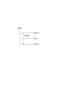
- a transfer function G may be provided that can take into account the continuity of the occurrence of deviations of the state quantity from the normal range.
- FIG. 13 is a diagram showing the transfer function G according to this embodiment.
- the determination unit 43 may treat the determination of normality or abnormality as a continuous quantity from 0 to 1, for example, and determine the presence or absence of a machining abnormality using a transfer function G such as a first-order lag.
- the determination unit 43 inputs into the transfer function G such as a first-order lag, a value indicating whether the state quantity X2 for each fixed period is normal or abnormal, with "0" indicating normality and "1" indicating abnormality.
- the determination unit 43 determines that only when the value output from the transfer function G exceeds the threshold value S is a machining abnormality. With this configuration, only abnormalities that have continued for a long time can be detected.
- the threshold value S may be changeable depending on the workpiece W to be processed and the processing conditions.
- the calculation unit 42 calculates the normal range of the state quantity It may be calculated separately.
- the determination unit 43 may perform abnormality determination for each sensor value individually.
- the determination unit 43 may determine that there is a processing abnormality if even one of the determination results for each sensor value is detected as a deviation from the normal range, that is, an abnormality in the sensor value.
- the present invention is not limited to this form. For example, if an upper limit number of items is set that allows abnormalities in sensor values, and abnormalities in sensor values exceeding the number of items are detected, it may be determined as a machining abnormality. good.
- the determination unit 43 may generate a total score by giving specific weight to the abnormality determination of each sensor value. Then, the determination unit 43 may determine that there is a processing abnormality when the score exceeds a predetermined value. Note that the predetermined value may be changeable depending on the workpiece W to be processed and the processing conditions.
- the determination unit 43 correlates the behavior of the plurality of sensor values to generate a state quantity X3, which is a new determination index.
- An abnormality determination may be performed on the generated state quantity X3.
- the calculation unit 42 calculates the normal range of the state quantity X3 for each movement related value using the above-described method such as the table 100 and the calculation formulas exemplified in equations (3) to (5).
- the equipment to which the abnormality determination device 3 is applied is not limited to the laser processing machine 1, but may include a plotter that draws pictures using NC (Numerical Control), a skiving machine that performs skiving processing, or a machining center. Applicable to
- (Configuration 1) Processing of the workpiece in a processing device having a moving part that moves relative to the workpiece, and a processing part that is provided in the moving part and processes the workpiece while moving with the moving part relative to the workpiece.
- An abnormality determination device that determines an abnormality, a sensor unit that detects a state quantity related to processing of the workpiece by the processing device; an acquisition unit that acquires a movement relationship value regarding the movement of the movement unit;
- the state quantity detected by the sensor unit is acquired by the acquisition unit when the processing unit moves relative to the workpiece as the moving unit moves and performs normal machining on the workpiece.
- An abnormality determination device comprising: (Configuration 2) The movement relationship value includes a movement speed of the movement unit. The abnormality determination device according to configuration 1. (Configuration 3) The movement relationship value includes a movement direction of the movement unit. The abnormality determination device according to configuration 1 or configuration 2.
- the moving unit is a laser head included in the laser processing machine,
- the processing section is a laser emitting section of the laser head that emits a laser beam,
- An abnormality determination device according to any one of configurations 1 to 3.
- the calculation unit calculates a table indicating the normal range for each of the movement related values based on the information accumulated in the storage unit,
- the determination unit determines whether the state quantity detected by the sensor unit is within the normal range based on the table.
- An abnormality determination device according to any one of configurations 1 to 4.
- the calculation unit derives an arithmetic expression for calculating the normal range for each movement-related value based on the information accumulated in the storage unit, The determination unit determines whether the state quantity detected by the sensor unit is within the normal range based on the calculation formula.
- An abnormality determination device in any one of configurations 1 to 5.
- the sensor unit detects at least one of light amount, temperature, sound, and image analysis result as the state quantity.
- An abnormality determination device according to any one of configurations 1 to 6.
- (Configuration 8) a laser head that moves relative to the workpiece; a laser emitting section that is provided on the laser head and moves with the laser head relative to the workpiece and emits a laser beam to the workpiece to process the workpiece; configuration 1;
- a laser processing machine comprising: the abnormality determination device according to any one of configurations 7 to 7. (Configuration 9) a head control device that stops processing the workpiece when the determination unit determines that the state quantity detected by the sensor unit is outside the normal range; The laser processing machine according to configuration 8. (Configuration 10) If the determination unit determines that the state quantity detected by the sensor unit is outside the normal range, move the laser head until the state quantity detected by the sensor unit falls within the normal range. comprising a head control device that changes speed; The laser processing machine according to configuration 8.
Landscapes
- Engineering & Computer Science (AREA)
- Physics & Mathematics (AREA)
- Optics & Photonics (AREA)
- Mechanical Engineering (AREA)
- Plasma & Fusion (AREA)
- Laser Beam Processing (AREA)
Abstract
Description
(a)レーザ光を収束・拡散させるための集光レンズ23の発熱を検出する温度センサ。
(b)加工用レーザ光L1の反射光の光量を検出する光量センサ。
(c)レーザヘッド12周辺の音を検出する音センサ。
(d)加工点付近の画像に基づき切断溝の大きさ、溶融金属の挙動を監視する画像センサ。
下限値=平均値-α2×標準偏差 …(2)
Xmax(v,θ)=a0V2+a1V+a2+b0sin(b1θ+b2) …(4)
Xmin(v,θ)=c0V2+c1V+c2+d0sin(d1θ+d2) …(5)
下限値=平均値-固定値 …(7)
ΔX´(t)=(X(t)-ΔX(t-T))/(v(t)・T) …(9)
上記実施形態は、少なくとも以下の構成を開示する。
(構成1)
ワークに対して移動する移動部と、前記移動部に設けられ、前記移動部と共に前記ワークに対して移動しつつ前記ワークに対して加工を行う加工部と、を有する加工装置における前記ワークの加工異常を判定する異常判定装置であって、
前記加工装置による前記ワークの加工に関連する状態量を検出するセンサ部と、
前記移動部の移動に関する移動関係値を取得する取得部と、
前記移動部の移動に伴って前記加工部が前記ワークに対して移動しつつ前記ワークに正常な加工を行う際に、前記センサ部により検出される前記状態量を、前記取得部により取得された前記移動関係値と対応付けて蓄積する蓄積部と、
前記蓄積部に蓄積された情報に基づき、前記状態量の正常範囲を前記移動関係値毎に算出する算出部と、
前記正常範囲が算出された後において、前記移動部の移動に伴って前記加工部が前記ワークに対して移動しつつ前記ワークに加工を行う際に、前記センサ部により検出される前記状態量が前記正常範囲内であるか否かを、前記算出部による算出結果に基づいて判定する判定部と、
を備える、異常判定装置。
(構成2)
前記移動関係値は、前記移動部の移動速度を含む、
構成1に記載の異常判定装置。
(構成3)
前記移動関係値は、前記移動部の移動方向を含む、
構成1又は構成2に記載の異常判定装置。
(構成4)
前記移動部は、前記レーザ加工機に備えるレーザヘッドであり、
前記加工部は、レーザ光を射出する前記レーザヘッドのレーザ射出部である、
構成1から構成3のいずれかの構成に記載の異常判定装置。
(構成5)
前記算出部は、前記蓄積部に蓄積された情報に基づき、前記正常範囲を示すテーブルを、前記移動関係値毎に算出し、
前記判定部は、前記センサ部により検出される前記状態量が前記正常範囲内であるか否かを、前記テーブルに基づいて判定する、
構成1から構成4のいずれかの構成に記載の異常判定装置。
(構成6)
前記算出部は、前記蓄積部に蓄積された情報に基づき、前記移動関係値毎の前記正常範囲を算出するための演算式を導出し、
前記判定部は、前記センサ部により検出される前記状態量が前記正常範囲内であるか否かを、前記演算式に基づいて判定する、
構成1から構成5のいずれかの構成に異常判定装置。
(構成7)
前記センサ部は、前記状態量として、光量、温度、音、及び画像の解析結果のうち少なくとも1つを検出する、
構成1から構成6のいずれかの構成に記載の異常判定装置。
(構成8)
ワークに対して移動するレーザヘッドと、前記レーザヘッドに設けられ、前記レーザヘッドと共に前記ワークに対して移動しつつ前記ワークにレーザ光を射出して前記ワークを加工するレーザ射出部と、構成1から構成7のいずれかの構成に記載の異常判定装置と、を備えるレーザ加工機。
(構成9)
前記判定部により前記センサ部により検出される前記状態量が前記正常範囲外であると判定された場合、前記ワークの加工を停止するヘッド制御装置を備える、
構成8に記載のレーザ加工機。
(構成10)
前記判定部により前記センサ部により検出される前記状態量が前記正常範囲外であると判定された場合、前記センサ部により検出される前記状態量が前記正常範囲内となるまで前記レーザヘッドの移動速度を変化させるヘッド制御装置を備える、
構成8に記載のレーザ加工機。
2・・・加工装置
3・・・異常判定装置
12・・・レーザヘッド
30・・・センサ
31・・・異常判定部
40・・・取得部
41・・・蓄積部
42・・・算出部
43・・・判定部
44・・・出力部
Claims (11)
- ワークに対して移動する移動部と、前記移動部に設けられ、前記移動部と共に前記ワークに対して移動しつつ前記ワークに対して加工を行う加工部と、を有する加工装置における前記ワークの加工異常を判定する異常判定装置であって、
前記移動部に設けられ、前記移動部と共に前記ワークに対して移動しつつ前記加工装置による前記ワークの加工に関連する状態量を検出するセンサ部と、
前記移動部の移動に関する移動関係値を取得する取得部と、
前記移動部の移動に伴って前記加工部が前記ワークに対して移動しつつ前記ワークに正常な加工を行う際に、前記センサ部により検出される前記状態量を、前記取得部により取得された前記移動関係値と対応付けて蓄積する蓄積部と、
前記蓄積部に蓄積された情報に基づき、前記状態量の正常範囲を前記移動関係値毎に算出する算出部と、
前記正常範囲が算出された後において、前記移動部の移動に伴って前記加工部が前記ワークに対して移動しつつ前記ワークに加工を行う際に、前記センサ部により検出される前記状態量が前記正常範囲内であるか否かを、前記算出部による算出結果に基づいて判定する判定部と、
を備える、異常判定装置。 - 前記移動関係値は、前記移動部の移動速度を含む、
請求項1に記載の異常判定装置。 - 前記移動関係値は、前記移動部の移動方向を含む、
請求項1に記載の異常判定装置。 - 前記移動部は、前記レーザ加工機に備えるレーザヘッドであり、
前記加工部は、レーザ光を射出する前記レーザヘッドのレーザ射出部である、
請求項1に記載の異常判定装置。 - 前記算出部は、前記蓄積部に蓄積された情報に基づき、前記正常範囲を示すテーブルを、前記移動関係値毎に算出し、
前記判定部は、前記センサ部により検出される前記状態量が前記正常範囲内であるか否かを、前記テーブルに基づいて判定する、
請求項1に記載の異常判定装置。 - 前記算出部は、前記蓄積部に蓄積された情報に基づき、前記移動関係値毎の前記正常範囲を算出するための演算式を導出し、
前記判定部は、前記センサ部により検出される前記状態量が前記正常範囲内であるか否かを、前記演算式に基づいて判定する、
請求項1に記載の異常判定装置。 - 前記センサ部は、前記状態量として、光量、温度、音、及び画像の解析結果のうち少なくとも1つを検出する、
請求項1に記載の異常判定装置。 - ワークに対して移動するレーザヘッドと、前記レーザヘッドに設けられ、前記レーザヘッドと共に前記ワークに対して移動しつつ前記ワークにレーザ光を射出して前記ワークを加工するレーザ射出部と、前記ワークの加工異常を判定する異常判定装置と、を備えるレーザ加工機であって、
前記異常判定装置は、
前記レーザヘッドに設けられ、前記レーザヘッドと共に前記ワークに対して移動しつつ前記レーザ加工機の状態量を検出するセンサ部と、
前記レーザヘッドの移動に関する移動関係値を取得する取得部と、
前記レーザヘッドの移動に伴って前記レーザ射出部が前記ワークに対して移動しつつ前記ワークに正常な加工を行う際に、前記センサ部により検出される前記状態量を、前記取得部により取得された前記移動関係値と対応付けて蓄積する蓄積部と、
前記蓄積部に蓄積された情報に基づき、前記状態量の正常範囲を、前記移動関係値毎に算出する算出部と、
前記正常範囲が算出された後において、前記レーザヘッドが前記ワークに対して移動しつつ前記ワークに加工を行う際に、前記センサ部により検出される前記状態量が前記正常範囲内であるか否かを、前記算出部による算出結果に基づいて判定する判定部と、
を備える、レーザ加工機。 - 前記判定部により前記センサ部により検出される前記状態量が前記正常範囲外であると判定された場合、前記ワークの加工を停止するヘッド制御装置を備える、
請求項8に記載のレーザ加工機。 - 前記判定部により前記センサ部により検出される前記状態量が前記正常範囲外であると判定された場合、前記センサ部により検出される前記状態量が前記正常範囲内となるまで前記レーザヘッドの移動速度を変化させるヘッド制御装置を備える、
請求項8に記載のレーザ加工機。 - ワークに対して移動する移動部と、前記移動部に設けられ、前記移動部と共に前記ワークに対して移動しつつ前記ワークに対して加工を行う加工部と、を有する加工装置における前記ワークの加工異常を判定する方法であって、
前記移動部の移動に伴って前記加工部が前記ワークに対して移動しつつ前記ワークに正常に加工を行う際に、前記移動部と共に前記ワークに対して移動するセンサ部により前記加工装置の状態量を検出することと、
前記移動部の移動に関する移動関係値を取得部により取得することと、
前記センサ部により検出される前記状態量を、前記取得部により取得された前記移動関係値と対応付けて蓄積部により蓄積することと、
前記蓄積部に蓄積された情報に基づき、前記状態量の正常範囲を、算出部により前記移動関係値毎に算出することと、
前記正常範囲が算出された後において、前記移動部の移動に伴って前記加工部が前記ワークに対して移動しつつ前記ワークに加工を行う際に、前記センサ部により検出される前記状態量が前記正常範囲内であるか否かを、前記算出部による算出結果に基づいて判定することと、
を含む、異常判定方法。
Priority Applications (2)
| Application Number | Priority Date | Filing Date | Title |
|---|---|---|---|
| JP2024533648A JPWO2024014335A1 (ja) | 2022-07-14 | 2023-07-03 | |
| CN202380052547.3A CN119546408A (zh) | 2022-07-14 | 2023-07-03 | 异常判定装置、激光加工机以及异常判定方法 |
Applications Claiming Priority (2)
| Application Number | Priority Date | Filing Date | Title |
|---|---|---|---|
| JP2022-113303 | 2022-07-14 | ||
| JP2022113303 | 2022-07-14 |
Publications (1)
| Publication Number | Publication Date |
|---|---|
| WO2024014335A1 true WO2024014335A1 (ja) | 2024-01-18 |
Family
ID=89536601
Family Applications (1)
| Application Number | Title | Priority Date | Filing Date |
|---|---|---|---|
| PCT/JP2023/024579 Ceased WO2024014335A1 (ja) | 2022-07-14 | 2023-07-03 | 異常判定装置、レーザ加工機、及び異常判定方法 |
Country Status (3)
| Country | Link |
|---|---|
| JP (1) | JPWO2024014335A1 (ja) |
| CN (1) | CN119546408A (ja) |
| WO (1) | WO2024014335A1 (ja) |
Citations (4)
| Publication number | Priority date | Publication date | Assignee | Title |
|---|---|---|---|---|
| JP2000153379A (ja) * | 1998-11-19 | 2000-06-06 | Sumitomo Heavy Ind Ltd | レーザ溶接の溶接状態判定方法および溶接状態判定装置 |
| JP2017113789A (ja) * | 2015-12-24 | 2017-06-29 | アイシン精機株式会社 | レーザ溶接装置 |
| JP2018079502A (ja) * | 2016-11-18 | 2018-05-24 | 日産自動車株式会社 | 溶接品質判定方法 |
| WO2019159659A1 (ja) * | 2018-02-16 | 2019-08-22 | パナソニックIpマネジメント株式会社 | レーザ溶接装置及びレーザ溶接方法 |
-
2023
- 2023-07-03 CN CN202380052547.3A patent/CN119546408A/zh active Pending
- 2023-07-03 JP JP2024533648A patent/JPWO2024014335A1/ja active Pending
- 2023-07-03 WO PCT/JP2023/024579 patent/WO2024014335A1/ja not_active Ceased
Patent Citations (4)
| Publication number | Priority date | Publication date | Assignee | Title |
|---|---|---|---|---|
| JP2000153379A (ja) * | 1998-11-19 | 2000-06-06 | Sumitomo Heavy Ind Ltd | レーザ溶接の溶接状態判定方法および溶接状態判定装置 |
| JP2017113789A (ja) * | 2015-12-24 | 2017-06-29 | アイシン精機株式会社 | レーザ溶接装置 |
| JP2018079502A (ja) * | 2016-11-18 | 2018-05-24 | 日産自動車株式会社 | 溶接品質判定方法 |
| WO2019159659A1 (ja) * | 2018-02-16 | 2019-08-22 | パナソニックIpマネジメント株式会社 | レーザ溶接装置及びレーザ溶接方法 |
Also Published As
| Publication number | Publication date |
|---|---|
| JPWO2024014335A1 (ja) | 2024-01-18 |
| CN119546408A (zh) | 2025-02-28 |
Similar Documents
| Publication | Publication Date | Title |
|---|---|---|
| JP5269260B1 (ja) | レーザ加工装置およびレーザ加工制御装置 | |
| US10761037B2 (en) | Laser processing device for determining the presence of contamination on a protective window | |
| JP6659654B2 (ja) | レーザ加工前に外部光学系の異常を警告するレーザ加工装置 | |
| JP6498553B2 (ja) | レーザー加工装置 | |
| CN112839765B (zh) | 用于求取加工过程的特征参量的方法和加工机 | |
| US20200016691A1 (en) | Laser machining device | |
| JP6189191B2 (ja) | 表面形状測定装置および工作機械 | |
| JP2008511449A (ja) | レーザ加工装置でのレーザ加工ビーム軸と加工ガス流軸の相互位置を求める方法、およびレーザ加工装置でのレーザ加工ビーム軸と加工ガス流軸の相互位置を調整する方法、ならびに当該方法に代わる装置を有するレーザ加工装置 | |
| US20220187782A1 (en) | Method for offset measure compensation | |
| JP6535480B2 (ja) | レーザ加工状態判別方法及び装置 | |
| CN113795350B (zh) | 用于监控工件的激光加工过程的方法 | |
| WO2024014335A1 (ja) | 異常判定装置、レーザ加工機、及び異常判定方法 | |
| US20210370438A1 (en) | Laser processing device | |
| US11590621B2 (en) | Machine tool and machining process change method | |
| US11110563B2 (en) | Non-contact tool setting apparatus and method | |
| JPH05329669A (ja) | レーザ加工機における加工制御装置 | |
| JP2015165210A (ja) | 表面形状測定装置およびそれを備えた工作機械 | |
| US20250010405A1 (en) | Laser machining method, and laser machine tool | |
| JP7629967B1 (ja) | レーザ加工機及び保護ガラスの汚れ検出方法 | |
| EP4032654B1 (en) | Laser processing device and processing state determination method | |
| JP3241557B2 (ja) | 先端の欠け検査装置 | |
| WO2025063095A1 (ja) | レーザ加工機及び加工不良検出方法 | |
| JP2024099275A (ja) | レーザ加工機、及びレーザ加工方法 | |
| JPH06142957A (ja) | レーザ加工装置 |
Legal Events
| Date | Code | Title | Description |
|---|---|---|---|
| 121 | Ep: the epo has been informed by wipo that ep was designated in this application |
Ref document number: 23839507 Country of ref document: EP Kind code of ref document: A1 |
|
| WWE | Wipo information: entry into national phase |
Ref document number: 2024533648 Country of ref document: JP |
|
| WWE | Wipo information: entry into national phase |
Ref document number: 202380052547.3 Country of ref document: CN |
|
| NENP | Non-entry into the national phase |
Ref country code: DE |
|
| WWP | Wipo information: published in national office |
Ref document number: 202380052547.3 Country of ref document: CN |
|
| 122 | Ep: pct application non-entry in european phase |
Ref document number: 23839507 Country of ref document: EP Kind code of ref document: A1 |