WO2024013970A1 - タービン及びターボチャージャ - Google Patents
タービン及びターボチャージャ Download PDFInfo
- Publication number
- WO2024013970A1 WO2024013970A1 PCT/JP2022/027810 JP2022027810W WO2024013970A1 WO 2024013970 A1 WO2024013970 A1 WO 2024013970A1 JP 2022027810 W JP2022027810 W JP 2022027810W WO 2024013970 A1 WO2024013970 A1 WO 2024013970A1
- Authority
- WO
- WIPO (PCT)
- Prior art keywords
- plate
- flow path
- turbine
- plate portion
- housing
- Prior art date
Links
- 230000002093 peripheral effect Effects 0.000 claims description 85
- 238000007789 sealing Methods 0.000 claims description 10
- 238000003780 insertion Methods 0.000 claims description 9
- 230000037431 insertion Effects 0.000 claims description 9
- 230000002829 reductive effect Effects 0.000 description 41
- 238000002485 combustion reaction Methods 0.000 description 18
- 230000007246 mechanism Effects 0.000 description 10
- 239000000463 material Substances 0.000 description 7
- 238000005452 bending Methods 0.000 description 5
- 230000006866 deterioration Effects 0.000 description 5
- 230000014509 gene expression Effects 0.000 description 5
- 238000011144 upstream manufacturing Methods 0.000 description 5
- 238000010586 diagram Methods 0.000 description 4
- 238000006073 displacement reaction Methods 0.000 description 4
- 230000007257 malfunction Effects 0.000 description 4
- 230000008859 change Effects 0.000 description 3
- 230000000694 effects Effects 0.000 description 3
- 239000012530 fluid Substances 0.000 description 3
- 238000003466 welding Methods 0.000 description 3
- 230000000670 limiting effect Effects 0.000 description 2
- 230000000717 retained effect Effects 0.000 description 2
- 229910000831 Steel Inorganic materials 0.000 description 1
- 230000000903 blocking effect Effects 0.000 description 1
- 230000003247 decreasing effect Effects 0.000 description 1
- 230000002401 inhibitory effect Effects 0.000 description 1
- 239000007769 metal material Substances 0.000 description 1
- 230000004048 modification Effects 0.000 description 1
- 238000012986 modification Methods 0.000 description 1
- 238000010248 power generation Methods 0.000 description 1
- 230000009467 reduction Effects 0.000 description 1
- 239000010959 steel Substances 0.000 description 1
Images


Classifications
-
- F—MECHANICAL ENGINEERING; LIGHTING; HEATING; WEAPONS; BLASTING
- F01—MACHINES OR ENGINES IN GENERAL; ENGINE PLANTS IN GENERAL; STEAM ENGINES
- F01D—NON-POSITIVE DISPLACEMENT MACHINES OR ENGINES, e.g. STEAM TURBINES
- F01D17/00—Regulating or controlling by varying flow
- F01D17/10—Final actuators
- F01D17/12—Final actuators arranged in stator parts
- F01D17/14—Final actuators arranged in stator parts varying effective cross-sectional area of nozzles or guide conduits
- F01D17/16—Final actuators arranged in stator parts varying effective cross-sectional area of nozzles or guide conduits by means of nozzle vanes
-
- F—MECHANICAL ENGINEERING; LIGHTING; HEATING; WEAPONS; BLASTING
- F02—COMBUSTION ENGINES; HOT-GAS OR COMBUSTION-PRODUCT ENGINE PLANTS
- F02B—INTERNAL-COMBUSTION PISTON ENGINES; COMBUSTION ENGINES IN GENERAL
- F02B37/00—Engines characterised by provision of pumps driven at least for part of the time by exhaust
- F02B37/12—Control of the pumps
- F02B37/24—Control of the pumps by using pumps or turbines with adjustable guide vanes
-
- Y—GENERAL TAGGING OF NEW TECHNOLOGICAL DEVELOPMENTS; GENERAL TAGGING OF CROSS-SECTIONAL TECHNOLOGIES SPANNING OVER SEVERAL SECTIONS OF THE IPC; TECHNICAL SUBJECTS COVERED BY FORMER USPC CROSS-REFERENCE ART COLLECTIONS [XRACs] AND DIGESTS
- Y02—TECHNOLOGIES OR APPLICATIONS FOR MITIGATION OR ADAPTATION AGAINST CLIMATE CHANGE
- Y02T—CLIMATE CHANGE MITIGATION TECHNOLOGIES RELATED TO TRANSPORTATION
- Y02T10/00—Road transport of goods or passengers
- Y02T10/10—Internal combustion engine [ICE] based vehicles
- Y02T10/12—Improving ICE efficiencies
Definitions
- the present disclosure relates to turbines and turbochargers.
- a turbocharger equipped with a variable capacity turbine is known as a turbocharger that supercharges the intake air of an internal combustion engine using the energy of the exhaust gas of the engine (see, for example, Patent Document 1).
- a variable capacity turbine a plurality of nozzle vanes are arranged in a line in the circumferential direction of the turbine wheel in the exhaust gas flow path for sending exhaust gas from the scroll flow path of the turbine to the turbine wheel, and the blade angles of these nozzle vanes are controlled from the outside.
- the cross-sectional area of the exhaust gas flow path (the flow path between adjacent nozzle vanes) can be adjusted.
- a variable capacity turbine increases the supercharging effect by adjusting the cross-sectional area of the exhaust gas flow path to change the flow velocity and pressure of the exhaust gas guided to the turbine wheel.
- variable nozzle mechanism When high temperature exhaust gas flows into the exhaust gas flow path of the variable capacity turbine, the variable nozzle mechanism may be thermally deformed.
- the nozzle support used in the variable nozzle mechanism has high rigidity, so if there is a difference in thermal expansion between the nozzle mount and the nozzle plate, large stress will be generated in the support part of the nozzle support, potentially damaging the nozzle support. In order to prevent damage to the nozzle support, it is necessary to increase the diameter of the nozzle support.
- At least one embodiment of the present disclosure aims to provide a turbine and a turbocharger that can suppress damage to members forming an exhaust gas flow path during thermal deformation.
- a turbine includes: a first housing having a scroll flow path; a turbine wheel provided on the inner peripheral side of the scroll flow path; a first plate member including an annular first plate portion; The gas flow from the scroll flow path toward the turbine wheel is arranged opposite to the first plate part on the tip side in the axial direction of the turbine wheel than the first plate part, and is arranged between the first plate part and the first plate part.
- a second plate member including an annular second plate portion forming a channel; at least one variable nozzle vane arranged in the gas flow path and rotatably supported by the first plate member or the second plate member; a second housing disposed closer to the rear end of the turbine wheel in the axial direction than the first plate member; a rear end side biasing member disposed between the second housing and the first plate member and configured to bias the first plate portion toward the gas flow path; Provided in the gas flow path, one end is connected to one of the first plate part or the second plate part, and the other end is connected to the other plate part of the first plate part or the second plate part. at least one support member that abuts.
- a turbocharger includes: the turbine; and a centrifugal compressor configured to be driven by the turbine.
- a turbine and a turbocharger are provided that can suppress damage to members forming an exhaust gas flow path during thermal deformation.
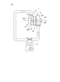
- FIG. 1 is a schematic diagram of an internal combustion engine system including a turbocharger according to one embodiment.
- FIG. 1 is a schematic cross-sectional view along the axis of a turbine according to one embodiment.
- FIG. 2 is a schematic diagram of a variable nozzle unit included in a turbine according to an embodiment.
- FIG. 2 is a schematic cross-sectional view showing an example of a cross section taken along an axis on one side of the axis of the turbine according to the first embodiment.
- FIG. 2 is a schematic cross-sectional view showing an example of a cross section taken along an axis on one side of the axis of the turbine according to the first embodiment.
- FIG. 2 is a schematic cross-sectional view showing an example of a cross section taken along an axis on one side of the axis of the turbine according to the first embodiment.
- FIG. 2 is a schematic cross-sectional view showing an example of a cross section taken along an axis on one side of the axis of the turbine according to the first embodiment.
- FIG. 7 is a schematic cross-sectional view showing an example of a cross section taken along an axis on one side of the axis of a turbine according to a second embodiment.
- FIG. 7 is a schematic cross-sectional view showing an example of a cross section taken along an axis on one side of the axis of a turbine according to a second embodiment.
- FIG. 7 is a schematic cross-sectional view showing an example of a cross section taken along an axis on one side of the axis of a turbine according to a second embodiment.
- FIG. 7 is a schematic cross-sectional view showing an example of a cross section taken along an axis on one side of the axis of a turbine according to a second embodiment.
- FIG. 7 is a schematic cross-sectional view showing an example of a cross section taken along an axis on one side of the axis of a turbine according to a second embodiment.
- FIG. 7 is a schematic cross-sectional view showing an example of a cross section taken along an axis on one side of the axis of a turbine according to a third embodiment.
- FIG. 7 is a schematic cross-sectional view showing an example of a cross section taken along an axis on one side of the axis of a turbine according to a third embodiment.
- FIG. 1 is a schematic diagram of an internal combustion engine system 10 including a turbocharger 1 according to an embodiment.
- the turbine 2 according to the present disclosure can be installed, for example, in a turbocharger 1 for automobiles, ships, or industrial use (for example, for land-based power generation).
- a turbine 2 mounted on a turbocharger 1 will be described as an example, but the turbine 2 according to the present disclosure is not limited to one mounted on the turbocharger 1.
- the turbine 2 of the present disclosure only needs to be capable of converting working fluid energy into mechanical power (for example, rotational force), and even if it is configured with the turbine 2 alone, it may be configured with a mechanism other than the centrifugal compressor 12 or It may also be configured in combination with a device. Furthermore, there is no need to limit the usage of the turbine 2.
- the turbocharger 1 is configured to be driven by the energy of exhaust gas discharged from an internal combustion engine (engine) 11 and compress fluid (for example, air). ing.
- the turbocharger 1 includes a turbine 2 and a centrifugal compressor 12 configured to be driven by the turbine 2.
- the centrifugal compressor 12 includes an impeller 13 and a compressor housing 14 configured to rotatably accommodate the impeller 13.
- the turbine 2 includes a turbine wheel 3, a first housing (turbine housing) 4, and a second housing (bearing housing) 5 configured to rotatably accommodate the turbine wheel 3 between the first housing 4. , at least.
- the turbocharger 1 includes a rotating shaft 15 to which a turbine wheel 3 is connected at one end and an impeller 13 at the other end, and a rotating shaft 15 between the turbine wheel 3 and the impeller 13. It further includes a bearing 16 configured to rotatably support the.
- the second housing 5 is disposed between the first housing 4 and the compressor housing 14, and is connected to each of the first housing 4 and the compressor housing 14 via fastening members (not shown) such as bolts and nuts. There is.
- the second housing 5 may be configured to accommodate the bearing 16.
- the turbine 2 of the turbocharger 1 is configured to rotate a turbine wheel 3 using the energy of exhaust gas discharged from the internal combustion engine 11. Since the impeller 13 is coaxially connected to the turbine wheel 3 via the rotating shaft 15, it is rotated around the axis LA in conjunction with the rotation of the turbine wheel 3.
- the centrifugal compressor 12 of the turbocharger 1 draws air (supply air, gas) into the compressor housing 14 by driving the impeller 13 to rotate around the axis LA, compresses the air, and converts the compressed air into compressed air. is configured to send the internal combustion engine 11 to the internal combustion engine 11.
- Compressed air sent from the centrifugal compressor 12 to the internal combustion engine 11 is provided for combustion in the internal combustion engine 11.
- Exhaust gas generated by combustion in the internal combustion engine 11 is sent from the internal combustion engine 11 to the turbine 2 to rotate the turbine wheel 3.
- the impeller 13 is connected to the other end of the rotating shaft 15, so that it is rotatable integrally with the rotating shaft 15 about the axis of the impeller 13.
- the impeller 13 is configured to guide air introduced along the axial direction of the impeller 13 to the outside in the radial direction of the impeller 13.
- the impeller 13 is an open type impeller that does not include an annular member surrounding the outer periphery of the blades of the impeller 13.
- compressor housing A gas introduction passage 141 and a scroll passage 142 are formed inside the compressor housing 14 .
- the compressor housing 14 has a gas introduction channel 141 and a scroll channel 142.
- the gas introduction channel 141 is a channel for taking in air (gas) from the outside of the compressor housing 14 (centrifugal compressor 12) and guiding the taken in air to the impeller 13.
- the gas introduction channel 141 is provided on one side of the impeller 13 in the axial direction of the impeller 13 and extends along the axial direction of the impeller 13 .
- the scroll flow path 142 is provided on the outer peripheral side of the impeller 13 and consists of a spiral flow path extending along the circumferential direction of the impeller 13. Air that passes through the impeller 13 and is compressed by the impeller 13 is guided to the scroll passage 142 . The compressed air that has passed through the scroll passage 142 is guided to the internal combustion engine 11.
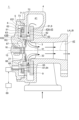
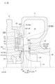
- FIG. 2 is a schematic cross-sectional view of the turbine 2 according to one embodiment along the axis LA.
- the direction in which the axis LA of the turbine wheel 3 extends is referred to as the axial direction of the turbine wheel 3 (turbine 2)
- the direction orthogonal to the axis LA is referred to as the radial direction of the turbine wheel 3 (turbine 2)
- the circumference around the axis LA is referred to as the radial direction of the turbine wheel 3 (turbine 2).
- the direction is the circumferential direction of the turbine wheel 3 (turbine 2).
- the side where the first housing 4 is located with respect to the second housing 5 in the axial direction of the turbine wheel 3 (turbine 2) (the right side in FIG. 2) is defined as the tip side
- the The side where the housing 5 is located is defined as the rear end side.
- the turbine wheel 3 includes a substantially truncated conical hub 31 and a plurality of turbine blades 32 provided on the outer peripheral surface of the hub 31, as shown in FIG. Each of the plurality of turbine blades 32 is arranged at intervals in the circumferential direction around the axis LA.
- the hub 31 and the plurality of turbine blades 32 are provided to be rotatable integrally with the rotating shaft 15 about the axis LA.
- the turbine wheel 3 is configured to guide exhaust gas introduced from the outside in the radial direction of the turbine wheel 3 to the tip side of the turbine wheel 3 along the axial direction of the turbine wheel 3.
- the turbine wheel 3 is an open-type impeller that does not include an annular member surrounding the outer periphery of the turbine blade 32.
- the scroll flow path 41 is provided on the outer peripheral side of the turbine wheel 3 and consists of a spiral flow path extending along the circumferential direction of the turbine wheel 3.
- the exhaust gas exhaust flow path 42 extends from the turbine wheel 3 toward the tip side along the axial direction of the turbine wheel 3.
- an internal space 43 is formed between the first housing 4 and the second housing 5, which connects the scroll passage 41 and the exhaust gas discharge passage 42.
- the turbine wheel 3 is housed in this internal space 43 so as to be rotatable relative to the first housing 4 and the second housing 5.
- the turbine wheel 3 is provided on the inner peripheral side of the scroll passage 41 .
- Exhaust gas discharged from the internal combustion engine 11 is guided to the turbine wheel 3 via the scroll passage 41, and drives the turbine wheel 3 to rotate.
- the exhaust gas that rotates the turbine wheel 3 is discharged to the outside of the first housing 4 (turbine 2) via the exhaust gas discharge passage 42.
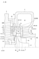
- FIG. 3 is a schematic diagram of the variable nozzle unit 6 included in the turbine 2 according to one embodiment.
- the turbine 2 further includes a variable nozzle unit 6 housed on the outer peripheral side of the turbine wheel 3 in the internal space 43 described above.
- the variable nozzle unit 6 forms a gas flow path (exhaust gas flow path) 43A for guiding exhaust gas from the scroll flow path 41 to the turbine wheel 3, and is for adjusting the flow of exhaust gas in the gas flow path 43A.
- the gas flow path 43A is a part of the internal space 43.
- the gas flow path 43A is formed between the scroll flow path 41 and the turbine wheel 3 so as to surround the periphery (radially outside) of the turbine wheel 3.
- variable nozzle unit 6 includes a first plate member (nozzle mount) 7, a second plate member (nozzle plate) 8, and at least one (in the illustrated example, a plurality of ), an annular member (drive ring) 62, and at least one (in the illustrated example, plural) link members (lever plates) 63.
- the variable nozzle unit 6 is configured to be able to vary the flow path area of gas supplied to the turbine wheel 3 by being mounted on the turbine 2 .
- the first plate member (nozzle mount) 7 includes an annular first plate portion 71 extending along the circumferential direction of the turbine wheel 3 on the outer peripheral side of the turbine wheel 3 .
- a first flow path surface 72 facing the gas flow path 43A is formed on the front end side of the first plate section 71 in the axial direction, and a first flow path surface 72 is formed on the rear end side of the first plate section 71 in the axial direction, that is, the first flow path surface 72.
- a first back surface 73 is formed on the opposite side.
- each of the first flow path surface 72 and the first back surface 73 is an annular surface extending along the circumferential direction of the turbine wheel 3.
- the second plate-like member (nozzle plate) 8 is arranged to face the first plate part 71, and has an annular shape that forms a gas flow path 43A from the scroll flow path 41 toward the turbine wheel 3 between the second plate member 8 and the first plate part 71.
- the second plate portion 81 includes a second plate portion 81 .
- the second plate portion 81 is disposed closer to the distal end side in the axial direction than the first plate portion 71 and extends along the circumferential direction of the turbine wheel 3 on the outer circumferential side of the turbine wheel 3 .
- a second flow path surface 82 facing the gas flow path 43A is formed on the rear end side of the second plate portion 81 in the axial direction, and the second flow path surface 82 is formed on the front end side of the second plate portion 81 in the axial direction, that is, the second flow path surface 82.
- a second back surface 83 is formed on the opposite side.
- each of the second flow path surface 82 and the second back surface 83 is an annular surface extending along the circumferential direction of the turbine wheel 3.
- the gas flow path 43A is formed between the first flow path surface 72 and the second flow path surface 82.
- the first flow path surface 72 is located closer to the rear end than the second flow path surface 82 in the axial direction, and faces the second flow path surface 82 .
- the exhaust gas introduced into the turbine 2 passes through the scroll passage 41 and then through the gas passage 43A, and is then led to the turbine wheel 3, causing the turbine wheel 3 to rotate.
- the second housing 5 has a rear end facing surface 51 that faces the first back surface 73 of the first plate portion 71 with the first space 43B interposed therebetween.
- the first space 43B is a part of the internal space 43, and is formed on the opposite side of the gas flow path 43A with the first plate portion 71 in between.
- Each of the plurality of variable nozzle vanes 61 is arranged in the gas flow path 43A, and has its own rotation axis RC on the first plate part 71 (first plate member 7) or the second plate part 81 (second plate member 8). It is rotatably supported.
- Each of the plurality of variable nozzle vanes 61 has a blade surface 64 facing the gas flow path 43A, a tip side end surface 65 formed at the tip side end of the blade surface 64 in the axial direction, and a tip side end surface 65 formed at the tip side end of the blade surface 64 in the axial direction.
- variable nozzle vanes 61 are arranged at intervals in the circumferential direction of the turbine wheel 3.
- the annular member (drive ring) 62 is arranged in the first space 43B and is configured to rotate around the axis LB of the annular member 62 with respect to the first plate member 7 by an external driving force.
- the turbine 2 includes a drive mechanism (actuator) 68 configured to transmit driving force to the annular member 62 and rotate the annular member 62 around its axis LB; It further includes a control device (controller) 69 configured to control rotation of the member 62 about the axis LB.
- the drive mechanism section 68 includes an electric motor that generates a driving force, an air cylinder that transmits the driving force, and the like.
- the variable nozzle unit 6 includes the same number of link members (lever plates) 63 as the variable nozzle vanes 61, as shown in FIG.
- Each of the plurality of link members 63 is arranged in the first space 43B, one end 631 is connected to the annular member 62, the other end 632 is connected to the variable nozzle vane 61, and the link member 63 is linked to the rotation of the annular member 62.
- the variable nozzle vane 61 connected to the other end 632 is configured to change the blade angle.
- each link member 63 includes a fitting portion 631A that fits into a fitted portion 621 formed on the annular member 62.
- the fitted portion 621 includes a groove 621A formed on the outer peripheral edge of the annular member 62, and the fitting portion 631A is accommodated inside the groove 621A and loosely fits into the groove 621A.
- the first plate portion 71 has a plurality of through holes 74 that penetrate the first flow path surface 72 and the first back surface 73.
- the plurality of through holes 74 are arranged at intervals in the circumferential direction of the turbine wheel 3 .
- the first plate portion 71 has the same number of through holes 74 as the variable nozzle vanes 61 and the link members 63.
- the other end of each link member 63 is connected to the tip (end on the rear end side) of the rotating shaft portion 67 of the variable nozzle vane 61 corresponding to the link member 63, which is inserted through the through hole 74.
- each of the plurality of variable nozzle vanes 61 is rotatably supported by the first plate member 7, but in some other embodiments, each of the plurality of variable nozzle vanes 61 is rotatably supported by the first plate member 7. Each may be rotatably supported by the second plate member 8.
- variable nozzle vanes 61 adjacent to each other in the circumferential direction move (rotate) in a direction away from each other, and the flow in the gas flow path 43A between the variable nozzle vanes 61 is reduced.
- the road cross-sectional area becomes larger.
- variable nozzle vanes 61 adjacent to each other in the circumferential direction move (rotate) in a direction toward each other, and the gas flow path between the variable nozzle vanes 61
- the cross-sectional area of the flow path 43A becomes smaller.
- the variable nozzle unit 6 transmits driving force from the outside of the variable nozzle unit 6 (drive mechanism section 68) to the plurality of variable nozzle vanes 61 via the annular member 62 and the plurality of link members 63.
- the cross-sectional area of the gas flow path 43A can be adjusted by rotating the blades 61 around their respective rotational axes RC and changing their blade angles.
- the turbine 2 can change the flow rate and pressure of the exhaust gas guided to the turbine wheel 3 by increasing/decreasing the cross-sectional area of the gas flow path 43A using the variable nozzle unit 6, and thereby the supercharging pressure of the turbine 2 can be changed. can be controlled.
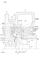
- FIGS. 4 to 9 are schematic cross-sectional view showing an example of a cross section along the axis LA on one side of the axis LA of the turbine 2 (2A) according to the first embodiment.
- the turbine 2 (2A) according to some embodiments includes the above-mentioned turbine wheel 3, the above-mentioned first housing 4, the above-mentioned second housing 5, and an annular
- the above-described first plate member 7 including the first plate portion 71, the above-described second plate member 8 including the annular second plate portion 81, and the first plate member 7 or the second plate member 8.
- the at least one variable nozzle vane 61 described above is rotatably supported.
- the gas flow path 43A is formed between the first flow path surface 72 and the second flow path surface 82.
- Each of the plurality of variable nozzle vanes 61 has a tip side end surface 65 facing the second flow path surface 82 with a gap therebetween, and a hub side end surface 66 facing the first flow path surface 72 with a gap therebetween.
- the turbine 2 (2A) is disposed between the second housing 5 and the first plate member 7, as shown in FIGS.
- a rear end side biasing member (back plate) 21 configured to bias toward the path 43A side, and one plate of the first plate portion 71 or the second plate portion 81 provided in the gas flow path 43A.
- the support member 9 further includes at least one (for example, a plurality of) support members 9 whose one end 91 is connected to the portion 71A and whose other end 92 abuts the other plate portion 81A of the first plate portion 71 or the second plate portion 81. .
- the rear end side biasing member 21 has an end surface 52 formed radially inwardly than the rear end side facing surface 51 of the second housing 5, and a first plate portion. 71 includes disk springs 21A that abut on respective end surfaces 75A of the inner peripheral edge portion 75 on the opposite side to the first flow path surface 72. The end surface 75A is formed inside the first back surface 73 in the radial direction.
- the first housing 4 includes a radially extending portion 44 that extends along the radial direction of the turbine wheel 3.
- the radially extending portion 44 has a rear scroll passage surface 441 that extends radially outward from the rear end P1, which is the rear end side end of the scroll passage 41 in the axial direction.
- the outer peripheral edge part 76 of the first plate part 71 is located on the inner side in the radial direction of the turbine wheel 3 than the inner peripheral end of the radially extending part 44 , and is biased by the rear end side biasing member 21 .
- the first plate member 7 is configured not to contact the radially extending portion 44 even if it moves along the axial direction of the turbine wheel 3.
- Each of the plurality of support members 9 is disposed upstream of the variable nozzle vane 61 in the gas flow path 43A, that is, on the outer side of the variable nozzle vane 61 in the radial direction of the turbine wheel 3.
- Each of the plurality of supporting members 9 supports the first plate-like member 7 and the second plate-like member 8 in a state where they are spaced apart from each other, and has a first gap between the first plate part 71 and the second plate part 81. G1 is formed.
- the plurality of support members 9 are arranged at intervals in the circumferential direction of the turbine wheel 3.
- Each of the plurality of support members 9 is formed into a rod shape extending along the axial direction of the turbine wheel 3.
- each of the plurality of support members 9 has one end 91, which is the rear end side (one side) in the axial direction, connected to the first plate part 71, and the front end side (the other side) in the axial direction.
- the other end 92 which is the end of , abuts on the second plate portion 81 .
- One end 91 of the support member 9 may be inserted into a hole formed in one plate portion 71A, and fixed to one plate portion 71A by caulking, welding, press fitting, or the like.
- the other end 92 of the support member 9 may be configured such that a flat end surface of the other end 92 comes into contact with the second flow path surface 82 of the second plate portion 81, as shown in FIG.
- each of the plurality of support members 9 has one end 91, which is the distal end (one side) in the axial direction, connected to the second plate part 81, and the rear end (other side) in the axial direction.
- the other end 92 which is the end of , abuts on the first plate portion 71 .
- One end 91 of the support member 9 may be inserted into a hole formed in one plate portion 71A, and fixed to one plate portion 71A by caulking, welding, press fitting, or the like.
- the other end 92 of the support member 9 may be configured such that a flat end surface of the other end 92 comes into contact with the first flow path surface 72 of the first plate part 71, as shown in FIG.
- the support member 9 since the support member 9 is pressed against the other plate portion 81A by the rear end side biasing member 21, it is possible to generate a frictional force between the support member 9 and the other plate portion 81A. can. Due to the frictional force, it is possible to suppress a shift in the relative positional relationship between the support member 9 and the other plate portion 81A. According to the above configuration, the support member 9 is not rigidly restrained in the radial direction with respect to at least one of the first plate member 7 and the second plate member 8.
- the members (first plate member 7, second plate member 8, support member 9) forming the gas flow path 43A are thermally deformed during operation of the turbine 2, the first plate member 7 and the second plate
- the stress generated in the support member 9 due to the difference in thermal expansion of the shaped member 8 can be reduced, and damage to the support member 9 when the members 7, 8, and 9 forming the gas flow path 43A are thermally deformed can be suppressed.
- the second plate member 8 whose outer peripheral edge and the like of the second plate portion 81 face the scroll flow path 41 is The amount of thermal elongation is larger than that of the plate member 7.
- the width dimension of the support member 9 can be reduced by reducing the stress generated in the support member 9 when the members 7, 8, and 9 forming the gas flow path 43A are thermally deformed. Therefore, the negative influence of the support member 9 on the inflow flow of the variable nozzle vane 61 can be reduced. Furthermore, it is not necessary to use high-strength materials that are expensive and poorly available for the support member 9. For the support member 9, for example, a relatively inexpensive and readily available metal material such as steel may be used.
- At least one support member 9 described above has one end 91 connected to the first plate part 71 and the other end 92 connected to the second plate part 71. It comes into contact with the plate portion 81 .
- one end 91 of the support member 9 is connected to the first plate part 71 that is biased by the rear end side biasing member 21, and the other end 92 of the support member 9 is brought into contact with the second plate part 81.
- the above-described first housing 4 has a distal side facing surface that faces the second back surface 83 of the above-described second plate portion 81 with a gap G2 in between. 45, and an annular contact portion 46 that protrudes from the distal end facing surface 45 and contacts the second back surface 83.
- the distal end facing surface 45 is located on the distal end side in the axial direction from the second back surface 83, and the annular contact portion 46 protrudes from the distal facing surface 45 toward the rear end side in the axial direction.
- the annular contact portion 46 extends along the circumferential direction of the turbine wheel 3 .
- the tip-side facing surface 45 of the first housing 4 and the second plate portion 81 can be brought into contact with each other. It is possible to seal the gap G2 between the rear surface 83 and the rear surface 83 of the camera. In this case, there is no need to separately provide a sealing member for sealing the gap G2, so the number of parts of the turbine 2 can be reduced.
- the annular contact portion 46 is an annular contact portion that abuts the second back surface 83 at least at a radial position through which the axis LD of the support member 9 passes. It has a contact surface 46A.
- the annular contact surface 46A is formed on the outer side of the front end side opposing surface 45 and the variable nozzle vane 61 in the radial direction of the turbine wheel 3. Note that at least the outer peripheral end of the annular contact portion 46 may face the scroll flow path 41, and the annular contact surface 46A may be continuous with the flow path surface forming the scroll flow path 41. You can.
- the annular contact portion 46 has the annular contact surface 46A that functions as a sealing surface that seals the gap G2 between the second plate portion 81 and the second back surface 83. It is possible to ensure a contact area on the contact surface between the annular contact portion 46 and the second back surface 83, thereby ensuring sealing performance. Further, according to the above configuration, by aligning the radial position through which the axis LD of the support member 9 passes and the radial position where the annular contact surface 46A is formed, bending stress generated in the second plate portion 81 , and deformation of the second plate portion 81 due to bending stress can be reduced.
- the support member 9 If the radial position where the annular abutting surface 46A is formed has a large deviation from the radial position through which the axis LD of the support member 9 passes, the support member 9 is pressed against the second plate portion 81. There is a possibility that a large bending stress is generated and the second plate portion 81 is deformed.
- the first housing 4 described above includes a cylindrical shroud part that is inserted into the center hole 84 of the second plate part 81 and covers the turbine wheel 3. Contains 47.
- the shroud portion 47 is located on the inner side in the radial direction of the turbine wheel 3 than the center hole 84 of the second plate portion 81 and the tip side opposing surface 45. Also protrudes toward the rear end side in the axial direction.
- the shroud portion 47 is a shroud surface 47A that is curved in a convex manner so as to face the tip side end surfaces (tips) of the plurality of turbine blades 32, and a gap (clearance) is formed between the shroud portion 47 and the tip side end surfaces of the turbine blades 32. has.
- a gap is formed between the center hole 84 of the second plate part 81 and the outer peripheral surface of the shroud part 47, and the shroud part 47 is loosely inserted into the center hole 84 of the second plate part 81.
- it is adapted to be inserted. Note that during operation of the turbine 2, the center hole 84 of the second plate part 81 and the outer peripheral surface of the shroud part 47 may or may not come into contact with each other.
- the other plate portion 81A described above is a recess 85A formed in the flow path surfaces 72, 82 facing the gas flow path 43A, and the bottom surface of the recess 85A is 851 has a recess 85A against which the other end 92 of at least one support member 9 comes into contact.
- the recess 85A may be an arcuate or annular groove extending along the circumferential direction of the turbine wheel 3, or a counterbored hole having a larger diameter than the other end 92 of the support member 9. Good too.
- the recessed part 85A is a counterbored hole, the positional shift of the other plate part 81A in the circumferential direction of the turbine wheel 3 can also be suppressed.
- the second plate part 81 corresponds to the other plate part 81A, and the recessed part 85A is formed in the second plate part 81, but as shown in FIG.
- a recessed portion 85A may be formed in the first plate portion 71.
- the other plate portion 81A described above has holes formed in the flow path surfaces 72, 82 (in the illustrated example, the flow path surface 82) facing the gas flow path 43A.
- the other end 92 of at least one support member 9 has a step surface 92A that contacts the flow path surfaces 72, 82 (in the illustrated example, the flow path surface 82) and a hole that protrudes beyond the step surface 92A.
- An insertion section 92B inserted into section 85B is included.
- the stepped surface 92A extends toward the outer circumferential side of the insertion portion 92B, and its outer circumferential edge is formed to have a larger diameter than the inner diameter of the hole portion 85B.
- the hole 85B is a through hole that penetrates the other plate 81A along its thickness direction (the above-mentioned axial direction), but the hole 85B is a bottomed hole. The depth of the bottomed hole may be greater than the length of the insertion portion 92B so that a gap is formed between the bottom of the bottomed hole and the insertion portion 92B.
- the insertion part 92B of the support member 9 is inserted into the hole 85B formed in the other plate part 81A, and the step surface 92A of the support member 9 is inserted into the channel surface 72, 82 of the other plate part 81A.
- the other plate part 81A and the support member 9 It is possible to suppress the occurrence of wear due to slippage between the second end 92 and the other end 92 .
- the other plate portion 81A (in the illustrated example, the second plate portion 81) is pressed against the other end 92 of the support member 9 by the urging force of the rear end side urging member 21. It is held by the frictional force generated between it and the other plate portion 81A.
- the force generated by vibration on the second plate member 8 due to engine vibration or the like increases as the mass of the second plate member 8 increases.
- the first housing 4 includes the shroud part 47, and the inner diameter D2 of the second plate part 81 is smaller than the inner diameter D1 of the first plate part 71. It's also big.
- the mass of the second plate member 8 can be reduced.
- the force caused by vibration can be reduced.
- the holding force (frictional force) for holding the supporting member 9 is small, the supporting member 9 can be held, and the sliding of the supporting member 9 with respect to the other plate portion 81A can be suppressed.
- the frictional force at the contact portion between the other plate portion 81A and the support member 9 and the contact portion between the annular contact portion 46 of the first housing 4 and the second plate portion 81 is reduced. Therefore, the risk of wear of these contact parts can be reduced.
- the amount of material used for the second plate member 8 can be reduced.
- the other plate part 81A (second plate part 81) is held by the above-mentioned frictional force generated by the urging force of the rear end side urging member 21, the other plate part 81A is moved in the above-mentioned radial direction. Since there is a risk of misalignment, it is preferable to combine the embodiments shown in FIGS. 6 and 9 in order to reduce this risk.
- the first housing 4 includes the shroud section 47
- the second plate section 81 includes a thick section 81B having a recess 85A or a hole 85B. and a thin wall portion 81C provided on the inner peripheral side of the thick wall portion 81B of the second plate portion 81, the thin wall portion 81C being thinner in the axial direction of the turbine wheel 3 than the thick wall portion 81B.
- the second back surface 83 is located closer to the rear end than the thick portion 81B in the axial direction.
- the mass of the second plate member 8 can be reduced.
- the force caused by vibration can be reduced.
- the holding force (frictional force) for holding the supporting member 9 is small, the supporting member 9 can be held, and the sliding of the supporting member 9 with respect to the other plate portion 81A can be suppressed.
- the frictional force at the contact portion between the other plate portion 81A and the support member 9 and the contact portion between the annular contact portion 46 of the first housing 4 and the second plate portion 81 is reduced. Therefore, the risk of wear of these contact parts can be reduced. Furthermore, the amount of material used for the second plate member 8 can be reduced.
- FIGS. 10 to 13 are schematic sectional views showing an example of a cross section along the axis LA on one side of the axis LA of the turbine 2 (2B) according to the second embodiment.
- the turbine 2 (2B) according to some embodiments includes the above-mentioned turbine wheel 3, the above-mentioned first housing 4 including the tip side facing surface 45, and the above-mentioned first housing 4.
- the gas flow path 43A is formed between the first flow path surface 72 and the second flow path surface 82.
- Each of the plurality of variable nozzle vanes 61 has a hub-side end surface 66 facing the first flow path surface 72 with a gap interposed therebetween.
- the turbine 2 (2B) includes a support member (for example, a support member 9) that supports the first plate member 7 and the second plate member 8 while being spaced apart from each other. ).
- the turbine 2 (2B) has a front end disposed between the second back surface 83 of the second plate part 81 and the front end facing surface 45 that faces the second back surface 83 of the first housing 4 with a gap G2 in between.
- a side biasing member 22 is further provided.
- the front end biasing member 22 is configured to bias the second plate portion 81 toward the gas flow path 43A side.
- the second plate portion 81 is pressed against each of the plurality of variable nozzle vanes 61 by the front end side biasing member 22, so that the second plate portion 81 is pressed against the tip side end surface 65 of each of the plurality of variable nozzle vanes 61.
- the flow path surface 82 is brought into contact with the flow path surface 82 .
- the second plate part 81 is pressed against the variable nozzle vane 61 by the front end side biasing member 22, so that the gap G2 between the second plate part 81 and the variable nozzle vane 61 can be minimized.
- a member such as the supporting member 9 that closes a part of the upstream side of the variable nozzle vane 61 in the gas flow path 43A. Efficiency can be improved.
- the closing member support member 9
- the instability of the variable nozzle vane 61 caused by the flow on the downstream side of the closing member in the gas flow path 43A being disturbed by the closing member. The behavior can be suppressed, thereby improving the reliability of the variable nozzle vane 61.
- the above-mentioned turbine 2 (2B) is arranged between the second housing 5 and the first plate member 7, as shown in FIGS. It further includes a rear end side biasing member 21 configured to bias toward the gas flow path 43A side.
- the first housing 4 described above extends along the radial direction of the turbine wheel 3 and is a housing on which the outer peripheral edge 76 of the first plate portion 71 urged by the rear end side urging member 21 is locked. It includes a locking portion (radially extending portion 44).
- the locked portion 44 has a locked surface 442 that is located on the opposite side (rear end side) in the axial direction from the rear scroll flow path surface 441 described above and faces the first space 43B.
- the first plate member 7 is biased toward the distal end side in the axial direction by the rear end side biasing member 21, so that the outer peripheral edge 76 of the first plate portion 71 is pressed against the locked portion of the first housing 4. 44, and a locking surface 76A formed on the distal end side in the axial direction of the outer peripheral edge portion 76 abuts against the locked surface 442. Thereby, the space between the locking surface 76A and the locked surface 442 is sealed, thereby suppressing the exhaust gas from flowing into the first space 43B from the scroll flow path 41.
- the outer peripheral edge 76 of the first plate portion 71 is pressed against the locked portion 44 of the first housing 4, thereby restricting movement of the first plate member 7 toward the distal end in the axial direction.
- the locking surface 76A is a stepped surface formed on the outer side and rear side of the first flow path surface 72 in the radial direction.
- the outer peripheral edge 76 of the first plate part 71 is sandwiched between the first housing 4 and the second housing 5, so that the axis of the first plate member 7 can be adjusted. Movement toward the distal end in the direction may be restricted.
- the first plate member 7 is biased by the rear end side biasing member 21 so that the outer peripheral edge 76 of the first plate portion 71 44 is pressed. That is, the first plate member 7 is caused by the frictional force generated between the outer peripheral edge 76 of the first plate portion 71 and the locked portion 44 of the first housing 4 due to the urging force of the rear end side urging member 21. Retained. Thereby, it is possible to suppress a shift in the relative position of the first plate member 7 with respect to the first housing 4 and the second housing 5.
- the front end side biasing member 22 described above includes an annular elastic seal member 22A that comes into contact with the second back surface 83 and the front side facing surface 45, respectively, as shown in FIGS. 10 to 13; 22B included.
- the front end side biasing member 22 includes a disc spring 22A that comes into contact with the second back surface 83 and the front end side opposing surface 45, respectively.
- the disc spring 22A is formed in an annular shape extending along the circumferential direction of the turbine wheel 3.
- the disc spring 22A front end side biasing member 22
- the front end side biasing member 22 includes the annular elastic seal members 22A and 22B, so that a pressing load can be applied to the second plate portion 81 toward the variable nozzle vane 61, and the second back surface 83 and the distal end facing surface 45 can be sealed, thereby suppressing gas leakage through the gap G2.
- the annular seal member 22B described above extends along the radial direction of the turbine wheel 3, and at least the outer peripheral end thereof is connected to the second plate portion 81, as shown in FIGS. 11 and 12.
- a first biasing plate portion 221 that abuts the back surface 83 of the turbine wheel 3
- a second biasing plate portion 222 that extends along the radial direction of the turbine wheel 3 and has at least an outer circumferential end that abuts the front end facing surface 45; It includes a connecting part 223 that connects the inner peripheral end of the first urging plate part 221 and the inner peripheral end of the second urging plate part 222.
- the annular seal member 22B may have a V-shape (see FIG. 11), a U-shape (see FIG. 12), or a W-shape in cross section.
- the annular elastic seal member 22B has the first urging plate part 221 in contact with the back surface 83 of the second plate part 81, and the second urging plate part 221 in contact with the front facing surface 45 of the first housing 4.
- the annular elastic seal member 22B includes a connecting portion 223 that connects the inner peripheral end of the first urging plate portion 221 and the inner peripheral end of the second urging plate portion 222, so that the turbine wheel It has an opening shape that opens outward in the radial direction of No. 3.
- the annular elastic seal member 22B having this opening shape has the first biasing plate portion 221 and the second biasing plate portion 222 separated by the pressure of the gas flowing outside the annular elastic seal member 22B in the radial direction. Since they are pushed apart from each other in the axial direction of the turbine wheel 3, the gap G2 between the back surface 83 of the second plate portion 81 and the front end side facing surface 45 of the first housing 4 can be effectively sealed. .
- the at least one variable nozzle vane 61 described above has at least a chip side end surface 65 that faces the second flow path surface 82 of the second plate part 81 with a gap therebetween. It includes a protrusion 651 that protrudes from the tip side end surface 65 and comes into contact with the second flow path surface 82 at a radial position where the rotation axis RC of the variable nozzle vane 61 passes.
- the protrusion 651 has a convex curved surface that is convex from the tip side end surface 65 toward the distal end side in the axial direction.
- the protrusion 651 of the variable nozzle vane 61 is brought into contact with the flow path surface 82 of the second plate part 81, and the radial position of the protrusion 651 and the radial position of the rotation axis RC of the variable nozzle vane 61 are aligned. Therefore, the radius of rotation of the friction application position on the tip side of the variable nozzle vane 61 (the distance between the friction application point on the tip side of the variable nozzle vane 61 and the rotation axis RC) can be made small, and thereby the variable nozzle vane The rotational driving force required to rotate 61 can be reduced.
- the at least one variable nozzle vane 61 has a hub side end surface 66 that faces the first flow path surface 72 of the first plate part 71 with a gap therebetween, and A rotation shaft portion 67 extending from the side end surface 66 along the rotation axis RC of the variable nozzle vane 61 is included.
- the above-described turbine 2 (2B) further includes an annular plate member (washer) 23 that is disposed between the first flow path surface 72 of the first plate portion 71 and the hub side end surface 66 and surrounds the rotating shaft portion 67.
- the annular plate member 23 may be configured such that the rotating shaft portion 67 is loosely inserted therethrough and comes into contact with each of the first flow path surface 72 and the hub side end surface 66.
- the variable nozzle vane 61 by disposing the annular plate member 23 surrounding the rotating shaft portion 67 between the hub side end surface 66 of the variable nozzle vane 61 and the first flow path surface 72 of the first plate portion 71, the variable nozzle vane 61
- the rotation radius of the friction application position on the hub side of the variable nozzle vane 61 (distance between the friction application point on the hub side of the variable nozzle vane 61 and the rotation axis RC) can be made small, thereby making the rotation of the variable nozzle vane 61 smooth. It can be done.
- the annular plate member 23 surrounding the rotating shaft portion 67 between the hub side end surface 66 and the first flow path surface 72 the vibration of the rotating shaft portion 67 can be suppressed. Rotation can be made smoother.
- the at least one variable nozzle vane 61 described above has a hub side end surface 66 that faces the first flow path surface 72 of the first plate section 71 with a gap therebetween. and a rotational shaft portion 67 extending from the hub side end surface 66 along the rotational axis RC of the variable nozzle vane 61.
- the front end biasing member 22 described above has a contact portion 224 that contacts the second back surface 83 of the second plate portion 81 at least at a radial position where the rotation axis RC of the variable nozzle vane 61 passes.
- the contact portion 224 is formed at least at the outer peripheral end portion of the first biasing plate portion 221.
- FIGS. 11 and 12 the contact portion 224 is formed at least at the outer peripheral end portion of the first biasing plate portion 221.
- the front end side urging member 22 by aligning the radial position of the contact portion 224 on which the urging force of the front end side urging member 22 acts with the radial position of the rotation axis RC of the variable nozzle vane 61, the front end side urging member 22 It is possible to prevent the biased second plate portion 81 from tilting with respect to the variable nozzle vane 61 and obstructing the rotational operation of the variable nozzle vane 61, thereby reducing malfunctions of the variable nozzle vane 61.
- the above-mentioned turbine 2 (2B) is provided on the inner peripheral side of the above-mentioned front end side urging member 22, as shown in FIGS. It further includes a positioning part 24 that limits the radial position of the.
- the positioning portion 24 is formed in an annular or arc shape extending along the circumferential direction of the turbine wheel 3, and is inserted into the center hole of the front end side biasing member 22. .
- the positioning portion 24 may be provided on the outer peripheral side of the shroud portion 47 described above, and the shroud portion 47 may be inserted therethrough.
- the positioning portion 24 may be a protruding portion that is formed integrally with the first housing 4 and protrudes from the distal end facing surface 45 toward the rear end in the axial direction on the inner peripheral side of the front end biasing member 22. . Further, the positioning portion 24 is a protrusion portion that is integrally formed with the second plate member 8 and protrudes from the second back surface 83 toward the distal end side in the axial direction on the inner peripheral side of the front end side biasing member 22. Good too. Further, the positioning portion 24 may be a separate body from each of the first housing 4 and the second plate member 8, and may be, for example, an annular body or an arcuate body extending along the circumferential direction of the turbine wheel 3. There may be.
- the radial position on which the biasing force of the front end side biasing member 22 acts can be adjusted to the rotation axis of the variable nozzle vane 61. It can be easily aligned to the radial position through which the RC passes.
- the positioning portion 24 by restricting the radial position of the front-end biasing member 22 by the positioning portion 24, it is possible to suppress deviation of the radial position on which the biasing force of the front-end biasing member 22 acts.
- the second plate portion 81 is prevented from tilting with respect to the variable nozzle vane 61 and inhibiting the rotational movement of the variable nozzle vane 61. This can reduce malfunctions of the variable nozzle vane 61.
- FIG. 14 and FIG. 15 are schematic sectional view showing an example of a cross section along the axis LA on one side of the axis LA of the turbine 2 (2C) according to the third embodiment.
- the turbine 2 (2C) according to some embodiments includes the above-mentioned turbine wheel 3, the above-mentioned first housing 4 including the tip side facing surface 45, and the above-mentioned first housing 4. 2 housing 5, the above-mentioned first plate member 7 including the annular first plate portion 71, and the above-mentioned at least one variable nozzle vane 61 rotatably supported by the first plate member 7. Be prepared.
- the turbine 2 (2C) includes a support member (for example, a support member 9) that supports the first plate member 7 and the second plate member 8 in a state where they are spaced apart from each other. , the second plate-like member 8.
- the annular first plate portion 71 includes a tip side facing surface 45 formed at a radial position between the scroll passage 41 and the turbine wheel 3 in the first housing 4.
- the gas flow path 43 ⁇ /b>C is arranged to face the front end side facing surface 45 and forms a gas flow path 43 ⁇ /b>C from the scroll flow path 41 toward the turbine wheel 3 .
- Each of the plurality of variable nozzle vanes 61 is arranged in the gas flow path 43C, and the hub side end surface 66 faces the first flow path surface 72 with a gap interposed therebetween.
- the turbine 2 (2C) includes an annular elastic seal that abuts each of the tip-side end surface 65 and the tip-side facing surface 45 of at least one (for example, a plurality of) variable nozzle vanes 61.
- a member 25 is provided.
- the annular elastic seal member 25 is configured to urge the tip side end surface 65 toward the first plate portion 71 side (the rear end side in the axial direction).
- the annular elastic seal member 25 is brought into contact with the tip side end surface 65 of the variable nozzle vane 61 and the tip side opposing surface 45 of the first housing 4, so that The gap G3 between the surface 45 and the surface 45 can be sealed. Further, according to the above configuration, by pressing the annular elastic seal member 25 against the variable nozzle vane 61, a frictional force can be generated between the annular elastic seal member 25 and the variable nozzle vane 61. Due to the frictional force, it is possible to suppress a deviation in the relative positional relationship between the annular elastic seal member 25 and the variable nozzle vane 61.
- the turbine 2 (2C) described above is arranged between the second housing 5 and the first plate member 7, as shown in FIGS. It further includes a rear end side biasing member 21 configured to bias toward the gas flow path 43C side.
- the first housing 4 described above extends along the radial direction of the turbine wheel 3 and is a housing on which the outer peripheral edge 76 of the first plate portion 71 urged by the rear end side urging member 21 is locked. It includes a locking portion (radially extending portion 44).
- the locked portion 44 has a locked surface 442 that is located on the opposite side (rear end side) in the axial direction from the rear scroll flow path surface 441 described above and faces the first space 43B.
- the first plate member 7 is biased toward the distal end side in the axial direction by the rear end side biasing member 21, so that the outer peripheral edge 76 of the first plate portion 71 is pressed against the locked portion of the first housing 4. 44, and a locking surface 76A formed on the distal end side in the axial direction of the outer peripheral edge portion 76 abuts against the locked surface 442. Thereby, the space between the locking surface 76A and the locked surface 442 is sealed, thereby suppressing the exhaust gas from flowing into the first space 43B from the scroll flow path 41.
- the outer peripheral edge 76 of the first plate portion 71 is pressed against the locked portion 44 of the first housing 4, thereby restricting movement of the first plate member 7 toward the distal end in the axial direction.
- the locking surface 76A is a stepped surface formed on the outer side and rear side of the first flow path surface 72 in the radial direction.
- the outer peripheral edge 76 of the first plate part 71 is sandwiched between the first housing 4 and the second housing 5, so that the axis of the first plate member 7 can be adjusted. Movement toward the distal end in the direction may be restricted.
- the first plate member 7 is biased by the rear end side biasing member 21 so that the outer peripheral edge 76 of the first plate portion 71 44 is pressed. That is, the first plate member 7 is caused by the frictional force generated between the outer peripheral edge 76 of the first plate portion 71 and the locked portion 44 of the first housing 4 due to the urging force of the rear end side urging member 21. Retained. Thereby, it is possible to suppress a shift in the relative position of the first plate member 7 with respect to the first housing 4 and the second housing 5.
- the annular elastic seal member 25 described above extends along the radial direction of the turbine wheel 3 and has at least one variable shape at least at its outer peripheral end, as shown in FIGS. 14 and 15.
- portion 252 , and a connecting portion 253 that connects the inner circumferential end of the first biasing plate portion 221 and the inner circumferential end of the second biasing plate portion 252 .
- the annular seal member 25 may have a V-shape (see FIG. 14), a U-shape (see FIG. 15), or a W-shape in cross section.
- the annular elastic seal member 25 has the first biasing plate portion 251 in contact with the tip side end surface 65 of the variable nozzle vane 61, and the second biasing plate portion 251 in contact with the tip side facing surface 45 of the first housing 4.
- the annular elastic seal member 25 includes a connecting portion 253 that connects the inner peripheral end of the first biasing plate portion 251 and the inner peripheral end of the second biasing plate portion 252, so that the turbine wheel It has an opening shape that opens outward in the radial direction of No. 3.
- the annular elastic seal member 25 having this opening shape has the first biasing plate portion 251 and the second biasing plate portion 252 separated by the pressure of the gas flowing outside the annular elastic seal member 25 in the radial direction. Since they are pushed apart from each other in the axial direction of the turbine wheel 3, the gap G3 between the tip side end surface 65 and the tip side opposing surface 45 can be effectively sealed.
- the at least one variable nozzle vane 61 has a tip side end surface 65 facing the tip side opposing surface 45 and a gas flow of the first plate part 71. It includes a hub-side end surface 66 that faces the first flow path surface 72 facing the passage 43C via a gap, and a rotation shaft portion 67 extending from the hub-side end surface 66 along the rotation axis RC of the variable nozzle vane 61.
- the annular elastic seal member 25 described above has a contact portion 254 that contacts the tip side end surface 65 at least at a radial position where the rotation axis RC of the variable nozzle vane 61 passes. In the embodiment shown in FIGS. 14 and 15, the contact portion 254 is formed at least at the outer peripheral end portion of the first biasing plate portion 251. In the embodiment shown in FIGS.
- the tip side end surface 65 and the tip The gap G3 between the side facing surface 45 can be effectively sealed.
- the above-mentioned turbine 2 (2C) is provided on the inner peripheral side of the above-mentioned annular elastic seal member 25, as shown in FIGS. 14 and 15. It further includes a positioning part 26 that limits the radial position of the.
- the positioning portion 26 is formed in an annular or arcuate shape extending along the circumferential direction of the turbine wheel 3, and is inserted into the center hole of the annular elastic seal member 25. .
- the positioning portion 26 may be provided on the outer peripheral side of the above-mentioned shroud portion 47 so that the shroud portion 47 is inserted therethrough.
- the positioning portion 26 may be a protruding portion that is integrally formed with the first housing 4 and protrudes from the distal end facing surface 45 toward the rear end in the axial direction on the inner peripheral side of the annular elastic seal member 25. . Further, the positioning portion 26 may be a separate body from the first housing 4, and may be, for example, an annular body or an arcuate body extending along the circumferential direction of the turbine wheel 3.
- the radial position of the annular elastic seal member 25 by the positioning part 26 by restricting the radial position of the annular elastic seal member 25 by the positioning part 26, the radial position on which the urging force of the annular elastic seal member 25 acts can be adjusted to the rotation axis of the variable nozzle vane 61. It can be easily aligned to the radial position through which the RC passes. Further, by restricting the radial position of the annular elastic seal member 25 by the positioning portion 26, it is possible to suppress the radial position on which the biasing force of the annular elastic seal member 25 is applied from shifting.
- the turbocharger 1 includes the above-mentioned turbine 2 (2A to 2C), the above-mentioned centrifugal compressor 12 configured to be driven by the turbine 2, Equipped with In this case, damage to the members forming the gas flow path 43A of the turbine 2 during thermal deformation can be suppressed, so the reliability of the turbocharger 1 equipped with the turbine 2 can be improved.
- expressions expressing shapes such as a square shape or a cylindrical shape do not only mean shapes such as a square shape or a cylindrical shape in a strict geometric sense, but also within the range where the same effect can be obtained. , shall also represent shapes including uneven parts, chamfered parts, etc.
- the expressions "comprising,””including,” or “having" one component are not exclusive expressions that exclude the presence of other components.
- the turbine (2) includes: a first housing (4) having a scroll channel (41); a turbine wheel (3) provided on the inner peripheral side of the scroll flow path (41); a first plate member (7) including an annular first plate portion (71); It is arranged opposite to the first plate part (71) on the distal end side in the axial direction of the turbine wheel (3) than the first plate part (71), and is arranged between the first plate part (71) and the first plate part (71).
- a second plate member (8) including an annular second plate portion (81) forming a gas flow path (43A) from the scroll flow path (41) toward the turbine wheel (3); at least one variable nozzle vane (61) arranged in the gas flow path (43A) and rotatably supported by the first plate member (7) or the second plate member (8); a second housing (5) disposed closer to the rear end of the turbine wheel (3) in the axial direction than the first plate member (7); It is arranged between the second housing (5) and the first plate member (7), and is configured to urge the first plate part (71) toward the gas flow path (43A).
- a rear end side biasing member (21) Provided in the gas flow path (43A), one end (91) is connected to one plate part (71A) of the first plate part (71) or the second plate part (81), and the other end (92) and at least one support member (9) that comes into contact with the other plate part (81A) of the first plate part (71) or the second plate part (81).
- the support member (9) is pressed against the other plate part (81A) by the rear end side biasing member (21), thereby causing the support member (9) and the other plate part (81A) can generate a frictional force between the two. Due to the frictional force, it is possible to suppress a shift in the relative positional relationship between the support member (9) and the other plate portion (81A).
- the support member (9) is rigidly restrained in the radial direction with respect to at least one of the first plate member (7) and the second plate member (8). do not have.
- the support member (9) by reducing the stress generated in the support member (9) when the members (7, 8, 9) forming the exhaust gas flow path (43A) are thermally deformed, the support member (9)
- the width dimension of the variable nozzle vane (61) can be reduced, and the negative influence of the support member (9) on the flow flowing into the variable nozzle vane (61) can be reduced. Furthermore, it is not necessary to use expensive and poorly available high-strength materials for the support member (9).
- the first housing (4) includes: a tip-side facing surface (45) facing the back surface (83) on the opposite side to the flow path surface (82) facing the gas flow path (43A) of the second plate portion (81) with a gap (G2) in between; and, It includes an annular contact portion (46) that protrudes from the tip side facing surface (45) and comes into contact with the back surface (83) of the second plate portion (81).
- the annular contact portion (46) is an annular contact portion that abuts the back surface (83) of the second plate portion (81) at least at a radial position through which the axis (LD) of the support member (9) passes. It has a contact surface (46A).
- the annular contact portion (46) functions as a sealing surface that seals the gap (G2) between the second plate portion (81) and the back surface (83).
- the contact surface (46A) By having the contact surface (46A), it is possible to secure a contact area on the contact surface between the annular contact portion (46) and the back surface (83) of the second plate portion (81), thereby ensuring sealing performance. can.
- configuration 3 by aligning the radial position through which the axis (LD) of the support member (9) passes and the radial position where the annular contact surface (46A) is formed, the first Bending stress generated in the second plate portion (81) and deformation of the second plate portion (81) due to the bending stress can be reduced.
- the first housing (4) includes: It includes a cylindrical shroud part (47) that is inserted into the center hole (84) of the second plate part (81) and covers the turbine wheel (3).
- the turbine (2) according to any one of 1) to 4) above,
- the other plate portion (81A) is a recess (85A) formed in the flow path surface (72, 82) facing the gas flow path (43A), and has a recess (85A) formed in the bottom surface (851) of the recess (85A). It has a recess (85A) against which the other end (92) of the at least one support member (9) comes into contact.
- the first housing (4) includes: It includes a cylindrical shroud part (47) that is inserted into the center hole (84) of the second plate part (81) and covers the turbine wheel (3),
- the second plate portion (81) has a larger inner diameter than the first plate portion (71).
- the support member (9) is connected to the other end (92) of the support member (9) and the other plate portion (81A) by the urging force of the rear end side urging member (21). It is held in place by the frictional force generated between the two.
- the force generated by vibration on the second plate member (8) due to engine vibration or the like increases as the mass of the second plate member (8) increases.
- the mass of the second plate member (8) can be reduced, and The force generated in the member (8) due to vibration can be reduced.
- the holding force for holding the supporting member (9)
- the supporting member (9) can be held, and the supporting member (9) is held against the other plate part (81A). It can prevent slipping.
- the contact portion between the other plate portion (81A) and the support member (9) and the annular contact portion (46) of the first housing (4) and the second plate portion Since the frictional force at the contact portion with 81) can be reduced, the risk of wear of these contact portions can be reduced. Furthermore, the amount of material used for the second plate member (8) can be reduced.
- the first housing (4) includes: It includes a cylindrical shroud part (47) that is inserted into the center hole (84) of the second plate part (81) and covers the turbine wheel (3),
- the second plate portion (81) is a thick portion (81B) having the recess (85A);
- a thin wall portion (81C) provided on the inner peripheral side of the thick wall portion (81B) of the second plate portion (81), the thin wall portion (81C) being provided on the inner peripheral side of the thick wall portion (81B) of the turbine wheel (3).
- a thin wall portion (81C) having a small thickness in the axial direction is included.
- the support member (9) is connected to the other end (92) of the support member (9) and the other plate portion (81A) by the urging force of the rear end side urging member (21). It is held in place by the frictional force generated between the two.
- the force generated by vibration on the second plate member (8) due to engine vibration or the like increases as the mass of the second plate member (8) increases.
- the holding force for holding the supporting member (9)
- the supporting member (9) can be held, and the supporting member (9) is held against the other plate part (81A). It can prevent slipping.
- the contact portion between the other plate portion (81A) and the support member (9) and the annular contact portion (46) of the first housing (4) and the second plate portion Since the frictional force at the contact portion with 81) can be reduced, the risk of wear of these contact portions can be reduced.
- the amount of material used for the second plate member (8) can be reduced.
- the turbine (2) according to any one of 1) to 7) above,
- the other plate portion (81A) has a hole (85B) formed in a flow path surface (72, 82) facing the gas flow path (43A),
- the other end (92) of the at least one support member (9) is a step surface (92A) that comes into contact with the flow path surface (72, 82);
- An insertion portion (92B) that protrudes from the step surface (92A) and is inserted into the hole (85B).
- the insertion portion (92B) of the support member (9) is inserted into the hole (85B) formed in the other plate portion (81A), and the stepped surface ( 92A) and the support member (92A) in the radial and circumferential directions of the turbine wheel (3). ) and the other end (92) of the support member (9), thereby suppressing the occurrence of wear due to slippage between the other plate portion (81A) and the other end (92) of the support member (9). can.
- the turbine (2) according to any one of 1) to 8) above,
- the one end (91) of the at least one support member (9) is connected to the first plate part (71), and the other end (92) abuts the second plate part (81).
- one end (91) of the support member (9) is connected to the first plate portion (71) that is biased by the rear end side biasing member (21), and the support member (9)
- the support member (9) By bringing the other end (92) into contact with the second plate portion (81), the support member (9) can be supported more easily than when the other end (92) of the support member (9) is brought into contact with the first plate portion (71).
- This is preferable because it reduces the risk that the positional relationship between the member (9) and the variable nozzle vane (61) will shift. This facilitates positioning during assembly of the variable nozzle unit (6), thereby improving the ease of assembling the variable nozzle unit (6).
- the turbine (2) includes: a first housing (4) having a scroll channel (41); a turbine wheel (3) provided on the inner peripheral side of the scroll flow path (41); a first plate member (7) including an annular first plate portion (71); It is arranged opposite to the first plate part (71) on the distal end side in the axial direction of the turbine wheel (3) than the first plate part (71), and is arranged between the first plate part (71) and the first plate part (71).
- a second plate member (8) including an annular second plate portion (81) forming a gas flow path (43A) from the scroll flow path (41) toward the turbine wheel (3); at least one variable nozzle vane (61) arranged in the gas flow path (43A) and rotatably supported by the first plate member (7) or the second plate member (8); a second housing (5) disposed closer to the rear end of the turbine wheel (3) in the axial direction than the first plate member (7); A back surface (83) of the second plate portion (81) opposite to the flow path surface (82) facing the gas flow path (43A), and a back surface (83) of the second plate portion (81) of the first housing (4). ), and a front end side biasing member (22) disposed between a front end side opposing surface (45) that faces the back surface (83) of the second plate portion (83) with a gap (G2) in between; 81) toward the gas flow path (43A).
- the second plate part (81) is pressed against the variable nozzle vane (61) by the front end side biasing member (22), so that the second plate part (81) and the variable nozzle vane (61)
- the gap (G2) between the two can be minimized.
- a member (closing member) such as the supporting member (9) that closes a part of the upstream side of the variable nozzle vane (61) in the gas flow path (43A) is disposed. Since it is not necessary, the efficiency of the turbine (2) can be improved.
- the turbine (2) described in 10) above It is arranged between the second housing (5) and the first plate member (7), and is configured to urge the first plate part (71) toward the gas flow path (43A). further comprising a rear end side biasing member (21),
- the first housing (4) extends along the radial direction of the turbine wheel (3), and the first plate portion (71) is biased by the rear end side biasing member (21).
- the outer peripheral edge (76) includes a locked portion (44) to which the outer peripheral edge (76) is locked.
- the first plate member (7) is biased by the rear end side biasing member (21), so that the outer peripheral edge (76) of the first plate portion (71) is pressed against the locked portion (44) of the first housing (4). That is, the first plate member (7) has the outer peripheral edge (76) of the first plate portion (71) locked by the first housing (4) due to the urging force of the rear end side urging member (21). It is held by the frictional force generated between the part (44) and the part (44). Thereby, it is possible to suppress the occurrence of a shift in the relative positional relationship of the first plate member (7) with respect to the first housing (4) and the second housing (5).
- the front end biasing member (22) includes annular elastic seal members (22A, 22B) that abut on the back surface (83) and the front facing surface (45) of the second plate portion (81), respectively. include.
- the front end side biasing member (22) includes the annular elastic seal members (22A, 22B), so that it is directed toward the variable nozzle vane (61) with respect to the second plate portion (81). Not only can a pressing load be applied, but also the gap (G2) between the back surface (83) of the second plate part (81) and the front end facing surface (45) of the first housing (4) can be sealed. ) can suppress gas leakage through
- the annular elastic seal member (22B) is a first biasing plate part (221) extending along the radial direction of the turbine wheel (3) and having at least an outer peripheral end abutting the back surface (83) of the second plate part (81); a second biasing plate portion (222) extending along the radial direction and having at least an outer peripheral end abutting the distal end facing surface (45);
- the connecting portion (223) connects the inner circumferential end of the first biasing plate (221) and the inner circumferential end of the second biasing plate (222).
- the annular elastic seal member (22B) brings the first biasing plate (221) into contact with the back surface (83) of the second plate (81), and the first housing ( By bringing the second biasing plate portion (222) into contact with the front end facing surface (45) of 4), a pressing load directed toward the variable nozzle vane (61) can be applied to the second plate portion (81). , the gap (G2) between the back surface (83) of the second plate portion (81) and the front end facing surface (45) of the first housing (4) can be sealed.
- the annular elastic seal member (22B) also has a connecting portion (223) that connects the inner peripheral end of the first biasing plate (221) and the inner peripheral end of the second biasing plate (222).
- the annular elastic seal member (22B) having this opening shape is moved between the first biasing plate portion (221) and the second biasing plate part (221) by the pressure of the gas flowing outside the annular elastic seal member (22B) in the radial direction. Since the rear plate portion (222) is pushed apart from each other in the axial direction of the turbine wheel (3), the back surface (83) of the second plate portion (81) and the front end side facing surface of the first housing (4) (45) can be effectively sealed.
- the at least one variable nozzle vane (61) includes: a chip-side end surface (65) that faces the flow path surface (82) of the second plate portion (81) with a gap therebetween; A projection that protrudes from the tip side end surface (65) and abuts the flow path surface (82) of the second plate portion (81) at least at a radial position through which the rotation axis (RC) of the variable nozzle vane (61) passes. 651).
- the protrusion (651) of the variable nozzle vane (65) is brought into contact with the flow path surface (82) of the second plate part (81), and the radial position of the protrusion (651) and the variable nozzle vane (
- the rotation radius of the friction acting position on the tip side of the variable nozzle vane (61) can be made small.
- the rotational driving force required for rotation can be reduced.
- the at least one variable nozzle vane (61) includes: a hub-side end surface (66) that faces the flow path surface (72) of the first plate portion (71) facing the gas flow path (43A) with a gap therebetween; a rotation shaft portion (67) extending from the hub side end surface (66) along the rotation axis (RC) of the variable nozzle vane (61);
- the turbine (2) is The apparatus further includes an annular plate member (23) disposed between the flow path surface (72) and the hub side end surface (66) of the first plate part (71) and surrounding the rotating shaft part (67).
- the annular plate member surrounding the rotating shaft portion (67) is located between the hub side end surface (66) of the variable nozzle vane (61) and the flow path surface (72) of the first plate portion (71).
- the rotation radius of the friction acting position on the hub side of the variable nozzle vane (61) can be made small, thereby making it possible to make the rotation of the variable nozzle vane (61) smooth.
- an annular plate member (23) surrounding the rotating shaft portion (67) is disposed between the hub side end surface (66) of the variable nozzle vane (61) and the flow path surface (72) of the first plate portion (71). Since the vibration of the rotating shaft portion (67) can be suppressed, the rotation of the variable nozzle vane (61) can also be made smooth.
- the turbine (2) according to any one of 10) to 15) above,
- the at least one variable nozzle vane (61) includes: a hub-side end surface (66) that faces the flow path surface (72) of the first plate portion (71) facing the gas flow path (43A) with a gap therebetween; a rotation shaft portion (67) extending from the hub side end surface (66) along the rotation axis (RC) of the variable nozzle vane (61);
- the front end biasing member (22) has an abutment that abuts the back surface (83) of the second plate portion (81) at least at a radial position through which the rotation axis (RC) of the variable nozzle vane (61) passes. It has a contact portion (224).
- the radial position of the contact portion (224) on which the urging force of the front end side urging member (22) acts is set to the radial position of the rotation axis (RC) of the variable nozzle vane (61).
- the second plate part (81) biased by the front end side biasing member (22) is prevented from tilting with respect to the variable nozzle vane (61) and obstructing the rotational operation of the variable nozzle vane (61). This can reduce malfunctions of the variable nozzle vane (61).
- the device further includes a positioning portion (24) provided on the inner peripheral side of the front end biasing member (22) to limit the radial position of the front end biasing member (22).
- the second plate portion (81) is tilted with respect to the variable nozzle vane (61), and the variable nozzle vane (61) It is possible to suppress the rotational movement of the variable nozzle vane (61), thereby reducing malfunction of the variable nozzle vane (61).
- the turbine (2) includes: a first housing (4) having a scroll channel (41); a turbine wheel (3) provided on the inner peripheral side of the scroll flow path (41); The front end side facing surface (45) is disposed opposite to the front end side facing surface (45) formed at a radial position between the scroll flow path (41) and the turbine wheel (3) in the first housing (4).
- the at least one variable nozzle vane (61) includes an annular elastic seal member (25) that comes into contact with each of the tip side end surface (65) and the tip side opposing surface (45).
- the annular elastic seal member (25) contacts each of the tip side end surface (65) of the variable nozzle vane (61) and the tip side facing surface (45) of the first housing (4). By contacting them, it is possible to seal the gap (G3) between the tip side end surface (65) and the tip side opposing surface (45). Further, according to configuration 18), the annular elastic seal member (25) is pressed against the variable nozzle vane (61), thereby causing friction between the annular elastic seal member (25) and the variable nozzle vane (61). can generate force. Due to the frictional force, it is possible to suppress a deviation in the relative positional relationship between the annular elastic seal member (25) and the variable nozzle vane (61).
- the configuration 18 there is no need to arrange a member (closing member) such as the supporting member (9) that closes a part of the upstream side of the variable nozzle vane (61) in the gas flow path (43C). Therefore, the efficiency of the turbine (2) can be improved.
- a member (closing member) such as the supporting member (9) that closes a part of the upstream side of the variable nozzle vane (61) in the gas flow path (43C). Therefore, the efficiency of the turbine (2) can be improved.
- configuration 18) above since there is no need to arrange the closing member (supporting member 9), the variable nozzle vane that occurs when the flow on the downstream side of the closing member in the gas flow path (43C) is disturbed by the closing member. (61) can be suppressed, thereby improving the reliability of the variable nozzle vane (61).
- the turbine (2) described in 18) above It is arranged between the second housing (5) and the first plate member (7), and is configured to urge the first plate part (71) toward the gas flow path (43C). further comprising a rear end side biasing member (21),
- the first housing (4) extends along the radial direction of the turbine wheel (3), and the first plate portion (71) is biased by the rear end side biasing member (21).
- the outer peripheral edge (76) includes a locked portion (44) to which the outer peripheral edge (76) is locked.
- the first plate member (7) is biased by the rear end side biasing member (21), so that the outer peripheral edge (76) of the first plate portion (71) is pressed against the locked portion (44) of the first housing (4). That is, the first plate member (7) has the outer peripheral edge (76) of the first plate portion (71) locked by the first housing (4) due to the urging force of the rear end side urging member (21). It is held by the frictional force generated between the part (44) and the part (44). Thereby, it is possible to suppress the occurrence of a shift in the relative positional relationship of the first plate member (7) with respect to the first housing (4) and the second housing (5).
- the annular elastic seal member (25) is a first biasing plate portion (251) extending along the radial direction of the turbine wheel (3) and having at least an outer peripheral end abutting the at least one tip side end surface (65); a second biasing plate portion (252) extending along the radial direction and having at least an outer peripheral end abutting the distal end facing surface (45);
- the connecting portion (253) connects the inner peripheral end of the first biasing plate (251) and the inner peripheral end of the second biasing plate (252).
- the annular elastic seal member (25) brings the first biasing plate (251) into contact with the tip-side end surface (65) of the variable nozzle vane (61), and the first housing ( By bringing the second biasing plate (252) into contact with the tip-side opposing surface (45) of 4), a pressing load can be applied to the variable nozzle vane (61), and the tip-side end surface (65) and tip The gap (G3) between the side facing surface (45) can be sealed.
- the annular elastic seal member (25) also has a connecting portion (253) that connects the inner peripheral end of the first biasing plate (251) and the inner peripheral end of the second biasing plate (252).
- the annular elastic seal member (25) having this opening shape is moved between the first biasing plate portion (251) and the second biasing plate portion (251) by the pressure of the gas flowing outside the annular elastic seal member (25) in the radial direction. Since the baffle plate portions (252) are pushed apart from each other in the axial direction of the turbine wheel (3), the gap (G3) between the tip side end surface (65) and the tip side facing surface (45) is effectively reduced. Can be sealed.
- the at least one variable nozzle vane (61) includes: a tip side end surface (65) opposite to the tip side opposing surface (45); a hub-side end surface (66) opposite to the flow path surface (72) of the first plate portion (71) facing the gas flow path (43C); a rotation shaft portion (67) extending from the hub side end surface (66) along the rotation axis (RC) of the variable nozzle vane (61);
- the annular elastic seal member (25) has a contact portion (254) that contacts the tip side end surface (65) at least at a radial position through which the rotation axis (RC) of the variable nozzle vane (61) passes. .
- the radial position of the contact portion (254) on which the urging force of the annular elastic seal member (25) acts is set to the radial position of the rotation axis (RC) of the variable nozzle vane (61).
- the gap (G3) between the tip side end surface (65) and the tip side facing surface (45) can be effectively sealed.
- gas leakage from the gap (G3) can be effectively suppressed when the variable nozzle vane (61) is closed, which has a large effect on the performance of the turbine (2) due to gas leakage from the gap (G3).
- Performance deterioration can be suppressed.
- the apparatus further includes a positioning part (26) provided on the inner peripheral side of the annular elastic seal member (25) to limit the radial position of the annular elastic seal member (25).
- the gap (G3) between the tip side end surface (65) and the tip side facing surface (45) can be suppressed. Gas leakage can be effectively suppressed, and performance deterioration of the turbine (2) can be suppressed.
- a turbocharger (1) according to at least one embodiment of the present disclosure, The turbine (2) according to any one of 1) to 22) above, a centrifugal compressor (12) configured to be driven by the turbine (2).
Landscapes
- Engineering & Computer Science (AREA)
- Mechanical Engineering (AREA)
- General Engineering & Computer Science (AREA)
- Chemical & Material Sciences (AREA)
- Combustion & Propulsion (AREA)
- Supercharger (AREA)
Abstract
タービンは、スクロール流路を有する第1ハウジングと、スクロール流路の内周側に設けられるタービンホイールと、環状の第1板部を含む第1板状部材と、第1板部よりも軸方向における先端側に第1板部に対向して配置され、第1板部との間にスクロール流路からタービンホイールに向かうガス流路を形成する環状の第2板部、を含む第2板状部材と、ガス流路に配置され、第1板状部材又は第2板状部材に回動可能に支持される少なくとも1つの可変ノズルベーンと、第1板状部材よりも軸方向における後端側に配置される第2ハウジングと、第2ハウジングと第1板状部材の間に配置され、第1板部をガス流路側に向かって付勢するように構成された後端側付勢部材と、ガス流路に設けられ、第1板部又は第2板部の一方の板部に一端が連結され、他端が第1板部又は第2板部の他方の板部に当接する少なくとも1つの支持部材と、を備える。
Description
本開示は、タービン及びターボチャージャに関する。
内燃機関(エンジン)の排ガスのエネルギを利用して内燃機関の吸気を過給するターボチャージャ(過給機)として、可変容量タービンを備えるものが知られている(例えば、特許文献1参照)。可変容量タービンは、該タービンのスクロール流路からタービンホイールに排ガスを送るための排ガス流路に複数のノズルベーンがタービンホイールの周方向に並んで配置されており、これらのノズルベーンの翼角を外部からアクチュエータにより変化させることで、排ガス流路の流路断面積(隣接するノズルベーン間の流路)を調整できるようになっている。可変容量タービンは、排ガス流路の流路断面積を調整することで、タービンホイールに導かれる排ガスの流速や圧力を変化させて過給効果を高めるものである。
可変容量タービンの性能向上のためには、ノズルベーンのベーン端面の隙間からの漏れ流れを抑制することが有効である。このため、従来はノズルサポートにより排ガス流路を形成する2つの板状部材(ノズルマウント、ノズルプレート)の距離を調整し、ベーン端面の隙間を最小に保つようにすることがあった。また、可変ノズル機構のハウジングへの組付けを容易にする目的で、ノズルサポートの両端をノズルマウント、ノズルプレートとかしめや溶接、圧入などにより固定することで可変ノズル機構を一体化する工夫がされることがある。
可変容量タービンの運転中において、可変容量タービンの排ガス流路に高温の排ガスが流入した際に、可変ノズル機構が熱変形することがある。可変ノズル機構に適用しているノズルサポートは剛性が高いため、ノズルマウントとノズルプレートに熱伸び差が生じると、大きな応力がノズルサポートのサポート部に生じ、ノズルサポートを破損させる虞がある。ノズルサポートの破損を防止するためには、ノズルサポートの径を大きくする必要がある。
上述の事情に鑑みて、本開示の少なくとも一実施形態は、排ガス流路を形成する部材の熱変形時における損傷を抑制できるタービン及びターボチャージャを提供することを目的とする。
本開示の少なくとも一実施形態に係るタービンは、
スクロール流路を有する第1ハウジングと、
前記スクロール流路の内周側に設けられるタービンホイールと、
環状の第1板部を含む第1板状部材と、
前記第1板部よりも前記タービンホイールの軸方向における先端側に前記第1板部に対向して配置され、前記第1板部との間に前記スクロール流路から前記タービンホイールに向かうガス流路を形成する環状の第2板部、を含む第2板状部材と、
前記ガス流路に配置され、前記第1板状部材又は前記第2板状部材に回動可能に支持される少なくとも1つの可変ノズルベーンと、
前記第1板状部材よりも前記タービンホイールの前記軸方向における後端側に配置される第2ハウジングと、
前記第2ハウジングと前記第1板状部材の間に配置され、前記第1板部を前記ガス流路側に向かって付勢するように構成された後端側付勢部材と、
前記ガス流路に設けられ、前記第1板部又は前記第2板部の一方の板部に一端が連結され、他端が前記第1板部又は前記第2板部の他方の板部に当接する少なくとも1つの支持部材と、を備える。
本開示の少なくとも一実施形態に係るターボチャージャは、
前記タービンと、
前記タービンにより駆動されるように構成された遠心圧縮機と、を備える。
前記タービンと、
前記タービンにより駆動されるように構成された遠心圧縮機と、を備える。
本開示の少なくとも一実施形態によれば、排ガス流路を形成する部材の熱変形時における損傷を抑制できるタービン及びターボチャージャが提供される。
以下、添付図面を参照して本開示の幾つかの実施形態について説明する。ただし、実施形態として記載されている又は図面に示されている構成部品の寸法、材質、形状、その相対的配置等は、本開示の範囲をこれに限定する趣旨ではなく、単なる説明例にすぎない。
(ターボチャージャ)
図1は、一実施形態に係るターボチャージャ1を備える内燃機関システム10の概略図である。本開示に係るタービン2は、例えば、自動車用、舶用又は産業用(例えば、陸上発電用)のターボチャージャ(過給機)1などに搭載可能である。以下の各実施形態では、ターボチャージャ1に搭載されるタービン2を例に挙げて説明するが、本開示に係るタービン2は、ターボチャージャ1に搭載されるものに限定されない。また、タービン2の作動流体を排ガスに限定する必要はない。すなわち、本開示のタービン2は、作動流体エネルギを機械的動力(例えば、回転力)に変換することが可能であればよく、タービン2単体で構成しても、遠心圧縮機12以外の機構や装置と複合して構成してもよい。また、タービン2の用途等を限定する必要もない。
図1は、一実施形態に係るターボチャージャ1を備える内燃機関システム10の概略図である。本開示に係るタービン2は、例えば、自動車用、舶用又は産業用(例えば、陸上発電用)のターボチャージャ(過給機)1などに搭載可能である。以下の各実施形態では、ターボチャージャ1に搭載されるタービン2を例に挙げて説明するが、本開示に係るタービン2は、ターボチャージャ1に搭載されるものに限定されない。また、タービン2の作動流体を排ガスに限定する必要はない。すなわち、本開示のタービン2は、作動流体エネルギを機械的動力(例えば、回転力)に変換することが可能であればよく、タービン2単体で構成しても、遠心圧縮機12以外の機構や装置と複合して構成してもよい。また、タービン2の用途等を限定する必要もない。
幾つかの実施形態に係るターボチャージャ1は、図1に示されるように、内燃機関(エンジン)11から排出された排ガスのエネルギにより駆動し、流体(例えば、空気)を圧縮するように構成されている。ターボチャージャ1は、タービン2と、タービン2により駆動されるように構成された遠心圧縮機12と、を備える。
遠心圧縮機12は、インペラ13と、インペラ13を回転可能に収容するように構成されたコンプレッサハウジング14と、を備える。タービン2は、タービンホイール3と、第1ハウジング(タービンハウジング)4と、第1ハウジング4との間にタービンホイール3を回転可能に収容するように構成された第2ハウジング(軸受ハウジング)5と、を少なくとも備える。
ターボチャージャ1は、図1に示されるように、タービンホイール3が一端側に連結され、他端側にインペラ13が連結される回転シャフト15と、タービンホイール3とインペラ13の間において回転シャフト15を回転可能に支持するように構成された軸受16と、をさらに備える。第2ハウジング5は、第1ハウジング4とコンプレッサハウジング14の間に配置され、例えば、ボルトやナットなどの締結部材(不図示)を介して第1ハウジング4及びコンプレッサハウジング14の夫々に連結されている。第2ハウジング5は、軸受16を収容するように構成されていてもよい。
ターボチャージャ1のタービン2は、内燃機関11から排出された排ガスのエネルギによりタービンホイール3を回転させるように構成されている。インペラ13は、回転シャフト15を介してタービンホイール3と同軸上に連結されているため、タービンホイール3の回転に連動して軸線LA回りに回転駆動する。ターボチャージャ1の遠心圧縮機12は、インペラ13を軸線LA回りに回転駆動させることにより、コンプレッサハウジング14の内部に空気(給気、気体)を吸入し、該空気を圧縮し、圧縮された空気を内燃機関11に送るように構成されている。
遠心圧縮機12から内燃機関11に送られた圧縮空気は、内燃機関11における燃焼に供されるようになっている。内燃機関11における燃焼により生じた排ガスは、内燃機関11からタービン2に送られ、タービンホイール3を回転させるようになっている。
(インペラ)
インペラ13は、図1に示されるように、回転シャフト15の他端側に連結されているため、インペラ13の軸線を中心として回転シャフト15と一体的に回転可能に設けられている。インペラ13は、インペラ13の軸方向に沿って導入される空気をインペラ13の径方向における外側に導くように構成されている。図示される実施形態では、インペラ13は、インペラ13の翼の外周を囲む環状部材を含まないオープンタイプのインペラからなる。
インペラ13は、図1に示されるように、回転シャフト15の他端側に連結されているため、インペラ13の軸線を中心として回転シャフト15と一体的に回転可能に設けられている。インペラ13は、インペラ13の軸方向に沿って導入される空気をインペラ13の径方向における外側に導くように構成されている。図示される実施形態では、インペラ13は、インペラ13の翼の外周を囲む環状部材を含まないオープンタイプのインペラからなる。
(コンプレッサハウジング)
コンプレッサハウジング14の内部には、気体導入流路141とスクロール流路142とが形成されている。換言すると、コンプレッサハウジング14は、気体導入流路141とスクロール流路142とを有する。
コンプレッサハウジング14の内部には、気体導入流路141とスクロール流路142とが形成されている。換言すると、コンプレッサハウジング14は、気体導入流路141とスクロール流路142とを有する。
気体導入流路141は、コンプレッサハウジング14(遠心圧縮機12)の外部から空気(気体)を取り込み、取り込んだ空気をインペラ13に導くための流路である。気体導入流路141は、インペラ13よりもインペラ13の軸方向における一方側に設けられ、インペラ13の軸方向に沿って延在している。インペラ13を回転駆動させることで、気体導入流路141にコンプレッサハウジング14の外部から空気が取り込まれ、取り込まれた空気が気体導入流路141をインペラ13に向かって流れてインペラ13に導かれる。
スクロール流路142は、インペラ13の外周側に設けられ、インペラ13の周方向に沿って延在する渦巻状の流路からなる。インペラ13を通過してインペラ13により圧縮された空気は、スクロール流路142に導かれる。スクロール流路142を通過した圧縮空気は、内燃機関11に導かれる。
図2は、一実施形態に係るタービン2の軸線LAに沿った概略断面図である。以下、タービンホイール3の軸線LAが延在する方向をタービンホイール3(タービン2)の軸方向とし、軸線LAに直交する方向をタービンホイール3(タービン2)の径方向とし、軸線LA回りの周方向をタービンホイール3(タービン2)の周方向とする。以下、タービンホイール3(タービン2)の軸方向において第2ハウジング5に対して第1ハウジング4が位置する側(図2中右側)を先端側と定義し、第1ハウジング4に対して第2ハウジング5が位置する側(上記先端側とは反対側、図2中左側)を後端側と定義する。
(タービンホイール)
タービンホイール3は、図2に示されるように、略円錐台形状のハブ31と、ハブ31の外周面に設けられた複数のタービン翼32と、を含む。複数のタービン翼32の夫々は、軸線LA周りの周方向に互いに間隔を開けて配置されている。ハブ31や複数のタービン翼32は、軸線LAを中心として回転シャフト15と一体的に回転可能に設けられている。タービンホイール3は、タービンホイール3の径方向における外側から導入される排ガスをタービンホイール3の軸方向に沿ってタービンホイール3の先端側に導くように構成されている。図示される実施形態では、タービンホイール3は、タービン翼32の外周を囲む環状部材を含まないオープンタイプのインペラからなる。
タービンホイール3は、図2に示されるように、略円錐台形状のハブ31と、ハブ31の外周面に設けられた複数のタービン翼32と、を含む。複数のタービン翼32の夫々は、軸線LA周りの周方向に互いに間隔を開けて配置されている。ハブ31や複数のタービン翼32は、軸線LAを中心として回転シャフト15と一体的に回転可能に設けられている。タービンホイール3は、タービンホイール3の径方向における外側から導入される排ガスをタービンホイール3の軸方向に沿ってタービンホイール3の先端側に導くように構成されている。図示される実施形態では、タービンホイール3は、タービン翼32の外周を囲む環状部材を含まないオープンタイプのインペラからなる。
(スクロール流路、排ガス排出流路)
第1ハウジング4の内部には、内燃機関11から排出された排ガスをタービンホイール3に導くためのスクロール流路41と、タービンホイール3を通過した排ガスを第1ハウジング4(タービン2)の外部に排出するための排ガス排出流路42が形成されている。換言すると、第1ハウジング4は、スクロール流路41及び排ガス排出流路42を有する。スクロール流路41は、タービンホイール3の外周側に設けられ、タービンホイール3の周方向に沿って延在する渦巻状の流路からなる。排ガス排出流路42は、タービンホイール3の軸方向に沿ってタービンホイール3から先端側に向かって延在している。
第1ハウジング4の内部には、内燃機関11から排出された排ガスをタービンホイール3に導くためのスクロール流路41と、タービンホイール3を通過した排ガスを第1ハウジング4(タービン2)の外部に排出するための排ガス排出流路42が形成されている。換言すると、第1ハウジング4は、スクロール流路41及び排ガス排出流路42を有する。スクロール流路41は、タービンホイール3の外周側に設けられ、タービンホイール3の周方向に沿って延在する渦巻状の流路からなる。排ガス排出流路42は、タービンホイール3の軸方向に沿ってタービンホイール3から先端側に向かって延在している。
第1ハウジング4と第2ハウジング5とが締結されることで、第1ハウジング4と第2ハウジング5の間に、スクロール流路41と排ガス排出流路42とを繋ぐ内部空間43が形成される。この内部空間43にタービンホイール3が第1ハウジング4及び第2ハウジング5に対して回転可能に収容されている。タービンホイール3は、スクロール流路41の内周側に設けられる。
内燃機関11から排出された排ガスは、スクロール流路41を介してタービンホイール3に導かれ、タービンホイール3を回転駆動させる。タービンホイール3を回転駆動させた排ガスは、排ガス排出流路42を介して第1ハウジング4(タービン2)の外部に排出される。
(可変ノズルユニット)
図3は、一実施形態に係るタービン2が備える可変ノズルユニット6の概略図である。タービン2は、図2に示されるように、上述した内部空間43におけるタービンホイール3の外周側に収容される可変ノズルユニット6をさらに備える。可変ノズルユニット6は、スクロール流路41からタービンホイール3へ排ガスを導くためのガス流路(排ガス流路)43Aを形成するとともに、ガス流路43Aにおける排ガスの流れを調整するためのものである。ガス流路43Aは、内部空間43の一部である。ガス流路43Aは、タービンホイール3の周囲(径方向における外側)を囲むように、スクロール流路41とタービンホイール3との間に形成されている。
図3は、一実施形態に係るタービン2が備える可変ノズルユニット6の概略図である。タービン2は、図2に示されるように、上述した内部空間43におけるタービンホイール3の外周側に収容される可変ノズルユニット6をさらに備える。可変ノズルユニット6は、スクロール流路41からタービンホイール3へ排ガスを導くためのガス流路(排ガス流路)43Aを形成するとともに、ガス流路43Aにおける排ガスの流れを調整するためのものである。ガス流路43Aは、内部空間43の一部である。ガス流路43Aは、タービンホイール3の周囲(径方向における外側)を囲むように、スクロール流路41とタービンホイール3との間に形成されている。
図2及び図3に示される実施形態では、可変ノズルユニット6は、第1板状部材(ノズルマウント)7と、第2板状部材(ノズルプレート)8と、少なくとも1つ(図示例では複数)の可変ノズルベーン61と、環状部材(ドライブリング)62と、少なくとも1つ(図示例では複数)のリンク部材(レバープレート)63と、を備える。可変ノズルユニット6は、タービン2に搭載されることでタービンホイール3に供給されるガスの流路面積を可変可能に構成されている。
(第1板状部材)
第1板状部材(ノズルマウント)7は、タービンホイール3の外周側においてタービンホイール3の周方向に沿って延在する環状の第1板部71を含む。第1板部71の上記軸方向における先端側にはガス流路43Aに面する第1流路面72が形成され、第1板部71の上記軸方向における後端側、すなわち第1流路面72とは反対側には第1背面73が形成されている。図示される実施形態では、第1流路面72及び第1背面73の夫々は、タービンホイール3の周方向に沿って延在する環状面からなる。
第1板状部材(ノズルマウント)7は、タービンホイール3の外周側においてタービンホイール3の周方向に沿って延在する環状の第1板部71を含む。第1板部71の上記軸方向における先端側にはガス流路43Aに面する第1流路面72が形成され、第1板部71の上記軸方向における後端側、すなわち第1流路面72とは反対側には第1背面73が形成されている。図示される実施形態では、第1流路面72及び第1背面73の夫々は、タービンホイール3の周方向に沿って延在する環状面からなる。
(第2板状部材)
第2板状部材(ノズルプレート)8は、第1板部71に対向して配置され、第1板部との間にスクロール流路41からタービンホイール3に向かうガス流路43Aを形成する環状の第2板部81を含む。第2板部81は、第1板部71よりも上記軸方向における先端側に配置され、タービンホイール3の外周側においてタービンホイール3の周方向に沿って延在している。第2板部81の上記軸方向における後端側にはガス流路43Aに面する第2流路面82が形成され、第2板部81の上記軸方向における先端側、すなわち第2流路面82とは反対側には第2背面83が形成されている。図示される実施形態では、第2流路面82及び第2背面83の夫々は、タービンホイール3の周方向に沿って延在する環状面からなる。
第2板状部材(ノズルプレート)8は、第1板部71に対向して配置され、第1板部との間にスクロール流路41からタービンホイール3に向かうガス流路43Aを形成する環状の第2板部81を含む。第2板部81は、第1板部71よりも上記軸方向における先端側に配置され、タービンホイール3の外周側においてタービンホイール3の周方向に沿って延在している。第2板部81の上記軸方向における後端側にはガス流路43Aに面する第2流路面82が形成され、第2板部81の上記軸方向における先端側、すなわち第2流路面82とは反対側には第2背面83が形成されている。図示される実施形態では、第2流路面82及び第2背面83の夫々は、タービンホイール3の周方向に沿って延在する環状面からなる。
ガス流路43Aは、第1流路面72と第2流路面82の間に形成される。第1流路面72は、第2流路面82よりも上記軸方向における後端側に位置し、第2流路面82に対向している。タービン2の内部に導入された排ガスは、スクロール流路41を通り、その次にガス流路43Aを通った後に、タービンホイール3に導かれて、タービンホイール3を回転させる。
第2ハウジング5は、第1板部71の第1背面73との間に第1空間43Bを挟んで対向する後端側対向面51を有する。第1空間43Bは、内部空間43の一部であり、第1板部71を挟んでガス流路43Aとは反対側に形成される。
(可変ノズルベーン)
複数の可変ノズルベーン61の各々は、ガス流路43Aに配置され、第1板部71(第1板状部材7)又は第2板部81(第2板状部材8)に各々の回転軸線RC回りに回動可能に支持されている。複数の可変ノズルベーン61の各々は、ガス流路43Aに面する翼面64と、翼面64の上記軸方向における先端側の端に形成されたチップ側端面65と、翼面64の上記軸方向における後端側の端に形成されたハブ側端面66と、ハブ側端面66から上記軸方向における後端側に向かって可変ノズルベーン61の回転軸線RCに沿って延在する回転軸部67と、を含む。複数の可変ノズルベーン61は、タービンホイール3の周方向に夫々が間隔をおいて配置されている。
複数の可変ノズルベーン61の各々は、ガス流路43Aに配置され、第1板部71(第1板状部材7)又は第2板部81(第2板状部材8)に各々の回転軸線RC回りに回動可能に支持されている。複数の可変ノズルベーン61の各々は、ガス流路43Aに面する翼面64と、翼面64の上記軸方向における先端側の端に形成されたチップ側端面65と、翼面64の上記軸方向における後端側の端に形成されたハブ側端面66と、ハブ側端面66から上記軸方向における後端側に向かって可変ノズルベーン61の回転軸線RCに沿って延在する回転軸部67と、を含む。複数の可変ノズルベーン61は、タービンホイール3の周方向に夫々が間隔をおいて配置されている。
(環状部材)
環状部材(ドライブリング)62は、第1空間43Bに配置され、外部からの駆動力により第1板状部材7に対して環状部材62の軸線LB回りに回動するように構成されている。
環状部材(ドライブリング)62は、第1空間43Bに配置され、外部からの駆動力により第1板状部材7に対して環状部材62の軸線LB回りに回動するように構成されている。
(駆動機構部、制御装置)
タービン2は、図2に示されるように、環状部材62に駆動力を伝達して、環状部材62をその軸線LB回りに回動させるように構成された駆動機構部(アクチュエータ)68と、環状部材62の軸線LB回りの回転を制御するように構成された制御装置(コントローラ)69と、をさらに備える。駆動機構部68は、駆動力を発生させる電動モータや駆動力を伝達するエアシリンダなどを含む。
タービン2は、図2に示されるように、環状部材62に駆動力を伝達して、環状部材62をその軸線LB回りに回動させるように構成された駆動機構部(アクチュエータ)68と、環状部材62の軸線LB回りの回転を制御するように構成された制御装置(コントローラ)69と、をさらに備える。駆動機構部68は、駆動力を発生させる電動モータや駆動力を伝達するエアシリンダなどを含む。
(リンク部材)
可変ノズルユニット6は、図3に示されるように、可変ノズルベーン61と同数のリンク部材(レバープレート)63を備える。複数のリンク部材63の各々は、第1空間43Bに配置され、環状部材62に一端631が連結され、可変ノズルベーン61に他端632が連結されており、環状部材62の回動に連動して他端632に連結された可変ノズルベーン61の翼角を変化させるように構成されている。
可変ノズルユニット6は、図3に示されるように、可変ノズルベーン61と同数のリンク部材(レバープレート)63を備える。複数のリンク部材63の各々は、第1空間43Bに配置され、環状部材62に一端631が連結され、可変ノズルベーン61に他端632が連結されており、環状部材62の回動に連動して他端632に連結された可変ノズルベーン61の翼角を変化させるように構成されている。
図3に示される実施形態では、各リンク部材63の一端631は、環状部材62に形成された被嵌合部621に嵌合する嵌合部631Aを含む。被嵌合部621は、環状部材62の外周縁部に形成される溝部621Aを含み、嵌合部631Aは、溝部621Aの内部に収容され、溝部621Aに緩く嵌合するようになっている。第1板部71には、第1流路面72及び第1背面73を貫通する複数の貫通孔74を有する。複数の貫通孔74は、タービンホイール3の周方向に夫々が間隔をおいて配置されている。第1板部71には、可変ノズルベーン61及びリンク部材63と同数の貫通孔74が形成されている。各リンク部材63の上記他端は、該リンク部材63に対応する可変ノズルベーン61の、貫通孔74を挿通した回転軸部67の先端部(後端側の端部)に連結されている。
図2に示される実施形態では、複数の可変ノズルベーン61の各々は、第1板状部材7に回動可能に支持されているが、他の幾つかの実施形態では、複数の可変ノズルベーン61の各々は、第2板状部材8に回動可能に支持されていてもよい。
環状部材62をタービンホイール3の周方向における一方側に回転させると、上記周方向において隣接する可変ノズルベーン61同士が互いに離れる方向に移動(回転)し、可変ノズルベーン61間のガス流路43Aの流路断面積が大きくなる。また、環状部材62をタービンホイール3の周方向における他方側に回転させると、上記周方向において隣接する可変ノズルベーン61同士が互いに近づく方向に移動(回動)し、可変ノズルベーン61間のガス流路43Aの流路断面積が小さくなる。
可変ノズルユニット6は、環状部材62及び複数のリンク部材63を介して可変ノズルユニット6の外部(駆動機構部68)からの駆動力を複数の可変ノズルベーン61に伝達させることで、複数の可変ノズルベーン61を各々の回転軸線RC回りに回動させ、各々の翼角を変化させることで、ガス流路43Aの流路断面積を調整できる。タービン2は、可変ノズルユニット6によりガス流路43Aの流路断面積を増減させることで、タービンホイール3に導かれる排ガスの流速や圧力を変化させることができ、これによりタービン2の過給圧を制御できる。
(第1の実施形態)
図4~図9の夫々は、第1の実施形態に係るタービン2(2A)の軸線LAよりも一方側の軸線LAに沿った断面の一例を示す概略断面図である。幾つかの実施形態に係るタービン2(2A)は、図4~図9に示されるように、上述したタービンホイール3と、上述した第1ハウジング4と、上述した第2ハウジング5と、環状の第1板部71を含む上述した第1板状部材7と、環状の第2板部81を含む上述した第2板状部材8と、第1板状部材7又は第2板状部材8に回動可能に支持される上述した少なくとも1つの可変ノズルベーン61と、を少なくとも備える。
図4~図9の夫々は、第1の実施形態に係るタービン2(2A)の軸線LAよりも一方側の軸線LAに沿った断面の一例を示す概略断面図である。幾つかの実施形態に係るタービン2(2A)は、図4~図9に示されるように、上述したタービンホイール3と、上述した第1ハウジング4と、上述した第2ハウジング5と、環状の第1板部71を含む上述した第1板状部材7と、環状の第2板部81を含む上述した第2板状部材8と、第1板状部材7又は第2板状部材8に回動可能に支持される上述した少なくとも1つの可変ノズルベーン61と、を少なくとも備える。
図4~図9に示される実施形態では、ガス流路43Aは、第1流路面72と第2流路面82との間に形成されている。複数の可変ノズルベーン61の各々は、チップ側端面65が隙間を介して第2流路面82に対向しており、ハブ側端面66が隙間を介して第1流路面72に対向している。
タービン2(2A)は、図4~図9に示されるように、第2ハウジング5と第1板状部材7の間に配置され、第1板状部材7の第1板部71をガス流路43A側に向かって付勢するように構成された後端側付勢部材(バックプレート)21と、ガス流路43Aに設けられ、第1板部71又は第2板部81の一方の板部71Aに一端91が連結され、他端92が第1板部71又は第2板部81の他方の板部81Aに当接する少なくとも1つ(例えば、複数)の支持部材9と、をさらに備える。
(後端側付勢部材)
図4~図9に示される実施形態では、後端側付勢部材21は、第2ハウジング5の後端側対向面51よりも径方向における内側に形成される端面52、および第1板部71の内周縁部75の第1流路面72とは反対側の端面75Aの夫々に当接する皿バネ21Aを含む。端面75Aは、第1背面73よりも径方向における内側に形成される。皿バネ21A(後端側付勢部材21)により、第2ハウジング5の端面52と第1板部71の端面75Aとの間がシールされることで、タービンホイール3の背面側から第1空間43Bへの排ガスの流入が抑制される。
図4~図9に示される実施形態では、後端側付勢部材21は、第2ハウジング5の後端側対向面51よりも径方向における内側に形成される端面52、および第1板部71の内周縁部75の第1流路面72とは反対側の端面75Aの夫々に当接する皿バネ21Aを含む。端面75Aは、第1背面73よりも径方向における内側に形成される。皿バネ21A(後端側付勢部材21)により、第2ハウジング5の端面52と第1板部71の端面75Aとの間がシールされることで、タービンホイール3の背面側から第1空間43Bへの排ガスの流入が抑制される。
図4~図9に示される実施形態では、第1ハウジング4は、タービンホイール3の径方向に沿って延在する径方向延在部44を含む。径方向延在部44は、スクロール流路41の上記軸方向における後端側の端である後方端P1から径方向の外側に延在する後方側スクロール流路面441を有する。第1板部71の外周縁部76は、径方向延在部44の内周端よりもタービンホイール3の径方向における内側に位置しており、後端側付勢部材21により付勢された第1板状部材7は、タービンホイール3の軸方向に沿って移動しても径方向延在部44に接触しないようになっている。
(支持部材)
複数の支持部材9の各々は、ガス流路43Aにおいて、可変ノズルベーン61よりも上流側、すなわち、可変ノズルベーン61よりもタービンホイール3の径方向における外側に配置されている。複数の支持部材9の各々は、第1板状部材7と第2板状部材8とを互いに離間した状態で支持し、第1板部71と第2板部81との間に第1隙間G1を形成するようになっている。複数の支持部材9は、タービンホイール3の周方向に夫々が間隔をおいて配置されている。複数の支持部材9の各々は、タービンホイール3の軸方向に沿って延在する棒状に形成されている。
複数の支持部材9の各々は、ガス流路43Aにおいて、可変ノズルベーン61よりも上流側、すなわち、可変ノズルベーン61よりもタービンホイール3の径方向における外側に配置されている。複数の支持部材9の各々は、第1板状部材7と第2板状部材8とを互いに離間した状態で支持し、第1板部71と第2板部81との間に第1隙間G1を形成するようになっている。複数の支持部材9は、タービンホイール3の周方向に夫々が間隔をおいて配置されている。複数の支持部材9の各々は、タービンホイール3の軸方向に沿って延在する棒状に形成されている。
図4、図6~図9に示される実施形態では、第1板部71が一方の板部71Aに相当し、第2板部81が他方の板部81Aに相当する。すなわち、複数の支持部材9の各々は、その上記軸方向における後端側(一方側)の端である一端91が第1板部71に連結され、その上記軸方向における先端側(他方側)の端である他端92が第2板部81に当接する。支持部材9の一端91は、一方の板部71Aに形成された孔に挿入され、かしめや溶接、圧入などにより一方の板部71Aに固定されてもよい。支持部材9の他端92は、図4に示されるように、他端92の平坦な端面が第2板部81の第2流路面82に当接するようになっていてもよい。
図5に示される実施形態では、第2板部81が一方の板部71Aに相当し、第1板部71が他方の板部81Aに相当する。すなわち、複数の支持部材9の各々は、その上記軸方向における先端側(一方側)の端である一端91が第2板部81に連結され、その上記軸方向における後端側(他方側)の端である他端92が第1板部71に当接する。支持部材9の一端91は、一方の板部71Aに形成された孔に挿入され、かしめや溶接、圧入などにより一方の板部71Aに固定されてもよい。支持部材9の他端92は、図5に示されるように、他端92の平坦な端面が第1板部71の第1流路面72に当接するようになっていてもよい。
上記の構成によれば、後端側付勢部材21により支持部材9が他方の板部81Aに押し付けられることで、支持部材9と他方の板部81Aとの間に摩擦力を生じさせることができる。該摩擦力により支持部材9と他方の板部81Aとの相対的な位置関係にずれが生じるのを抑制できる。上記の構成によれば、支持部材9が第1板状部材7又は第2板状部材8の少なくとも一方の部材に対して、上記径方向において剛に拘束されていない。このため、タービン2の運転時におけるガス流路43Aを形成する部材(第1板状部材7、第2板状部材8、支持部材9)の熱変形時に第1板状部材7と第2板状部材8の熱伸び差により支持部材9に発生する応力を低減でき、ガス流路43Aを形成する部材7、8、9の熱変形時における支持部材9の損傷を抑制できる。ここで、ガス流路43Aを形成する部材7、8、9の熱変形時において、第2板部81の外周縁部等がスクロール流路41に面する第2板状部材8は、第1板状部材7よりも熱伸び量が大きい。
上記の構成によれば、ガス流路43Aを形成する部材7、8、9の熱変形時に支持部材9に発生する応力を低減することで、支持部材9の幅寸法を小さなものとすることができ、支持部材9が可変ノズルベーン61の流入する流れに与える悪影響を低減できる。また、支持部材9に高価で入手性が悪い高強度材料を使用しなくても良くなる。支持部材9には、例えば、鋼鉄などの比較的安価な入手性が良好な金属材料を使用してもよい。
幾つかの実施形態では、図4、図6~図9に示されるように、上述した少なくとも1つの支持部材9は、その一端91が第1板部71に連結され、その他端92が第2板部81に当接する。この場合には、後端側付勢部材21に付勢される第1板部71に支持部材9の一端91を連結し、支持部材9の他端92を第2板部81に当接させることで、図5に示されるような、第1板部71に支持部材9の他端92を当接させる場合に比べて、支持部材9と可変ノズルベーン61との間の位置関係がずれるリスクを低減できるため、好ましい。これにより、可変ノズルユニット6の組立時における位置合わせが容易になるので、可変ノズルユニット6の組立性を向上できる。
(環状の当接部)
幾つかの実施形態では、図4~図9に示されるように、上述した第1ハウジング4は、上述した第2板部81の第2背面83に隙間G2を挟んで対向する先端側対向面45と、先端側対向面45から突出して第2背面83に当接する環状の当接部46と、を含む。先端側対向面45は、第2背面83よりも上記軸方向における先端側に位置し、環状の当接部46は、先端側対向面45から上記軸方向における後端側に向かって突出している。環状の当接部46は、タービンホイール3の周方向に沿って延在している。
幾つかの実施形態では、図4~図9に示されるように、上述した第1ハウジング4は、上述した第2板部81の第2背面83に隙間G2を挟んで対向する先端側対向面45と、先端側対向面45から突出して第2背面83に当接する環状の当接部46と、を含む。先端側対向面45は、第2背面83よりも上記軸方向における先端側に位置し、環状の当接部46は、先端側対向面45から上記軸方向における後端側に向かって突出している。環状の当接部46は、タービンホイール3の周方向に沿って延在している。
上記の構成によれば、第1ハウジング4の環状の当接部46を第2板部81の背面83に当接させることで、第1ハウジング4の先端側対向面45と第2板部81の背面83との間の隙間G2をシールすることができる。この場合には、上記隙間G2をシールするためのシール部材を別途設ける必要がないため、タービン2の部品点数を削減できる。
幾つかの実施形態では、図4~図9に示されるように、上述した環状の当接部46は、少なくとも支持部材9の軸線LDが通過する径方向位置において第2背面83に当接する環状の当接面46Aを有する。環状の当接面46Aは、先端側対向面45及び可変ノズルベーン61よりもタービンホイール3の径方向における外側に形成されている。なお、環状の当接部46は、少なくとも外周端部がスクロール流路41に面していてもよく、環状の当接面46Aは、スクロール流路41を形成する流路面に連なるようになっていてもよい。
上記の構成によれば、環状の当接部46は、第2板部81の第2背面83との間の隙間G2をシールするシール面として機能する環状の当接面46Aを有することで、環状の当接部46と第2背面83との当接面における当接面積を確保でき、これによりシール性能を確保できる。また、上記の構成によれば、支持部材9の軸線LDが通過する径方向位置と環状の当接面46Aが形成された径方向位置とを揃えることで、第2板部81に生じる曲げ応力、および曲げ応力による第2板部81の変形、を低減できる。
仮に、環状の当接面46Aが形成された径方向位置が、支持部材9の軸線LDが通過する径方向位置に対するずれが大きい場合には、支持部材9が押し付けられた第2板部81に大きな曲げ応力が生じ、第2板部81を変形させる虞がある。また、環状の当接面46Aが形成された径方向位置が、支持部材9の軸線LDが通過する径方向位置よりも径方向における内側にずれている場合には、スクロール流路41を流れる排ガスの熱が第2背面83から第2板部81を介して支持部材9に伝達され、支持部材9の温度が上昇して支持部材9の強度低下や変形のリスクが増加する虞がある。
(第1ハウジングのシュラウド部)
幾つかの実施形態では、図4~図9に示されるように、上述した第1ハウジング4は、第2板部81の中心孔84に挿通されるとともにタービンホイール3を覆う筒状のシュラウド部47を含む。
幾つかの実施形態では、図4~図9に示されるように、上述した第1ハウジング4は、第2板部81の中心孔84に挿通されるとともにタービンホイール3を覆う筒状のシュラウド部47を含む。
図4~図9に示される実施形態では、シュラウド部47は、第2板部81の中心孔84及び先端側対向面45よりもタービンホイール3の径方向における内側において、先端側対向面45よりも上記軸方向における後端側に突出している。シュラウド部47は、複数のタービン翼32のチップ側端面(先端)に対向するように凸状に湾曲し、タービン翼32のチップ側端面との間に隙間(クリアランス)が形成されるシュラウド面47Aを有する。
タービン2の運転時における第1ハウジング4や第2板状部材8の熱変形を考慮して、第1ハウジング4や第2板状部材8にタービン2の非運転時(タービン2の運転時における熱変形が生じていない場合)において、第2板部81の中心孔84とシュラウド部47の外周面との間に隙間が形成され、第2板部81の中心孔84にシュラウド部47が緩く挿入されるようになっていることが好ましい。なお、タービン2の運転時において、第2板部81の中心孔84とシュラウド部47の外周面とが接触してもよいし、接触しないようになっていてもよい。
(他方の板部に形成された凹部)
幾つかの実施形態では、図6に示されるように、上述した他方の板部81Aは、ガス流路43Aに面する流路面72、82に形成された凹部85Aであって、凹部85Aの底面851に少なくとも1つの支持部材9の他端92が当接する凹部85Aを有する。
幾つかの実施形態では、図6に示されるように、上述した他方の板部81Aは、ガス流路43Aに面する流路面72、82に形成された凹部85Aであって、凹部85Aの底面851に少なくとも1つの支持部材9の他端92が当接する凹部85Aを有する。
凹部85Aは、タービンホイール3の周方向に沿って延在する円弧状又は環状の溝部であってもよいし、支持部材9の他端92よりも大径の孔形状を有するザグリ穴であってもよい。
上記の構成によれば、他方の板部81Aに形成された凹部85Aの底面851に支持部材9の他端92を当接させることで、凹部85Aにより支持部材9の移動が制限されるため、タービンホイール3の径方向における他方の板部81Aの位置ずれが抑制される。これにより、上記他方の板部81Aと支持部材9の他端92の間の上記径方向における位置ずれを抑制でき、ひいては上記他方の板部81Aと支持部材9の他端92との間に生じるすべりによる摩耗の発生を抑制できる。なお、凹部85Aがザグリ穴である場合には、タービンホイール3の周方向における他方の板部81Aの位置ずれも抑制できる。また、図6に示される実施形態では、第2板部81が他方の板部81Aに相当し、この第2板部81に凹部85Aが形成されているが、図5に示されるような、第1板部71が他方の板部81Aに相当する場合において、第1板部71に凹部85Aを形成してもよい。
(他方の板部に形成された孔部)
幾つかの実施形態では、図9に示されるように、上述した他方の板部81Aは、ガス流路43Aに面する流路面72、82(図示例では、流路面82)に形成された孔部85Bを有し、上述した少なくとも1つの支持部材9の他端92は、流路面72、82(図示例では、流路面82)に当接する段差面92Aと、段差面92Aよりも突出して孔部85Bに挿入される挿入部92Bと、を含む。
幾つかの実施形態では、図9に示されるように、上述した他方の板部81Aは、ガス流路43Aに面する流路面72、82(図示例では、流路面82)に形成された孔部85Bを有し、上述した少なくとも1つの支持部材9の他端92は、流路面72、82(図示例では、流路面82)に当接する段差面92Aと、段差面92Aよりも突出して孔部85Bに挿入される挿入部92Bと、を含む。
段差面92Aは、挿入部92Bよりも外周側に延在し、その外周縁が孔部85Bの内径よりも大径に形成されている。図9に示される実施形態では、孔部85Bは、他方の板部81Aをその厚さ方向(上記軸方向)に沿って貫通する貫通孔であるが、孔部85Bは、有底孔であり、この有底孔の底部と挿入部92Bとの間に隙間が形成されるように、有底孔の深さが挿入部92Bの長さよりも大きくなっていてもよい。
上記の構成によれば、支持部材9の挿入部92Bを他方の板部81Aに形成された孔部85Bに挿入し、支持部材9の段差面92Aを他方の板部81Aの流路面72、82に当接させることで、タービンホイール3の径方向および周方向における他方の板部81Aと支持部材9の他端92との間の位置ずれを抑制でき、ひいては他方の板部81Aと支持部材9の他端92との間に生じるすべりによる摩耗の発生を抑制できる。
(第2板状部材の軽量化)
図7及び図8に示されるように、上述した他方の板部81A(図示例では、第2板部81)は、後端側付勢部材21の付勢力により支持部材9の他端92と他方の板部81Aとの間で生じる摩擦力により保持されている。ここで、エンジン振動などの作用により、第2板状部材8に振動により生じる力は、第2板状部材8の質量が大きくなる程増大する。
図7及び図8に示されるように、上述した他方の板部81A(図示例では、第2板部81)は、後端側付勢部材21の付勢力により支持部材9の他端92と他方の板部81Aとの間で生じる摩擦力により保持されている。ここで、エンジン振動などの作用により、第2板状部材8に振動により生じる力は、第2板状部材8の質量が大きくなる程増大する。
幾つかの実施形態では、図7に示されるように、上述した第1ハウジング4は、上述したシュラウド部47を含み、第2板部81の内径D2は、第1板部71の内径D1よりも大きい。
上記の構成によれば、第2板部81の内径D2を第1板部71の内径D1よりも大きくすることで、第2板状部材8の質量を低減でき、第2板状部材8に振動により生じる力を低減できる。この場合には、支持部材9を保持するための保持力(摩擦力)が小さくても支持部材9を保持でき、支持部材9が他方の板部81Aに対してすべることを抑制できる。上記保持力を小さなものとすることで、他方の板部81Aと支持部材9との接触部や第1ハウジング4の環状の当接部46と第2板部81との接触部における摩擦力を低減できるため、これらの接触部の摩耗リスクを低減できる。また、第2板状部材8に使用する材料の量を低減できる。なお、他方の板部81A(第2板部81)が、後端側付勢部材21の付勢力により生じる上記摩擦力により保持されている場合には、他方の板部81Aの上記径方向へのずれのリスクがあるため、このリスクを低減するために、図6や図9に示される実施形態と組み合わせることが好ましい。
幾つかの実施形態では、図8に示されるように、上述した第1ハウジング4は、上述したシュラウド部47を含み、第2板部81は、凹部85A又は孔部85Bを有する肉厚部81Bと、第2板部81の肉厚部81Bよりも内周側に設けられる薄肉部81Cであって、肉厚部81Bよりもタービンホイール3の軸方向における厚みが薄い薄肉部81Cと、を含む。薄肉部81Cは、第2背面83が肉厚部81Bよりも上記軸方向における後端側に位置している。
上記の構成によれば、第2板部81に肉厚部81Bよりも厚みが薄い薄肉部81Cを形成することで、第2板状部材8の質量を低減でき、第2板状部材8に振動により生じる力を低減できる。この場合には、支持部材9を保持するための保持力(摩擦力)が小さくても支持部材9を保持でき、支持部材9が他方の板部81Aに対してすべることを抑制できる。上記保持力を小さなものとすることで、他方の板部81Aと支持部材9との接触部や第1ハウジング4の環状の当接部46と第2板部81との接触部における摩擦力を低減できるため、これらの接触部の摩耗リスクを低減できる。また、第2板状部材8に使用する材料の量を低減できる。
(第2の実施形態)
図10~図13の夫々は、第2の実施形態に係るタービン2(2B)の軸線LAよりも一方側の軸線LAに沿った断面の一例を示す概略断面図である。幾つかの実施形態に係るタービン2(2B)は、図10~図13に示されるように、上述したタービンホイール3と、先端側対向面45を含む上述した第1ハウジング4と、上述した第2ハウジング5と、環状の第1板部71を含む上述した第1板状部材7と、環状の第2板部81を含む上述した第2板状部材8と、第1板状部材7又は第2板状部材8に回動可能に支持される上述した少なくとも1つの可変ノズルベーン61と、を少なくとも備える。
図10~図13の夫々は、第2の実施形態に係るタービン2(2B)の軸線LAよりも一方側の軸線LAに沿った断面の一例を示す概略断面図である。幾つかの実施形態に係るタービン2(2B)は、図10~図13に示されるように、上述したタービンホイール3と、先端側対向面45を含む上述した第1ハウジング4と、上述した第2ハウジング5と、環状の第1板部71を含む上述した第1板状部材7と、環状の第2板部81を含む上述した第2板状部材8と、第1板状部材7又は第2板状部材8に回動可能に支持される上述した少なくとも1つの可変ノズルベーン61と、を少なくとも備える。
図10~図13に示される実施形態では、ガス流路43Aは、第1流路面72と第2流路面82との間に形成されている。複数の可変ノズルベーン61の各々は、ハブ側端面66が隙間を介して第1流路面72に対向している。
タービン2(2B)は、図10~図13に示されるように、上述した第1板状部材7と第2板状部材8とを互いに離間した状態で支持する支持部材(例えば、支持部材9)を備えてはいない。タービン2(2B)は、第2板部81の第2背面83と、第1ハウジング4の第2背面83に隙間G2を挟んで対向する先端側対向面45と、の間に配置される前端側付勢部材22をさらに備える。前端側付勢部材22は、第2板部81をガス流路43A側に向かって付勢するように構成されている。
図10に示される実施形態では、前端側付勢部材22により第2板部81が複数の可変ノズルベーン61の各々に押し付けられることで、複数の可変ノズルベーン61の各々のチップ側端面65に第2流路面82が当接するようになっている。
上記の構成によれば、前端側付勢部材22により第2板部81が可変ノズルベーン61に押し付けられることで、第2板部81と可変ノズルベーン61との間の隙間G2を最小化できる。また、上記の構成によれば、上記支持部材9のような、ガス流路43Aにおける可変ノズルベーン61の上流側の一部を閉塞する部材(閉塞部材)を配置しなくて良いので、タービン2の効率の向上が図れる。上記の構成によれば、閉塞部材(支持部材9)を配置しなくて良いので、ガス流路43Aにおける閉塞部材の下流側の流れが閉塞部材により乱されることで生じる可変ノズルベーン61の不安定挙動を抑制でき、これにより可変ノズルベーン61の信頼性を向上させることができる。また、上記の構成によれば、閉塞部材(支持部材9)を配置しなくて良いので、タービン2の部品点数を削減できる。
(被係止部)
幾つかの実施形態では、上述したタービン2(2B)は、図10~図13に示されるように、第2ハウジング5と第1板状部材7の間に配置され、第1板部71をガス流路43A側に向かって付勢するように構成された後端側付勢部材21をさらに備える。上述した第1ハウジング4は、タービンホイール3の径方向に沿って延在するとともに、後端側付勢部材21に付勢された第1板部71の外周縁部76が係止される被係止部(径方向延在部44)を含む。
幾つかの実施形態では、上述したタービン2(2B)は、図10~図13に示されるように、第2ハウジング5と第1板状部材7の間に配置され、第1板部71をガス流路43A側に向かって付勢するように構成された後端側付勢部材21をさらに備える。上述した第1ハウジング4は、タービンホイール3の径方向に沿って延在するとともに、後端側付勢部材21に付勢された第1板部71の外周縁部76が係止される被係止部(径方向延在部44)を含む。
被係止部44は、上述した後方側スクロール流路面441とは上記軸方向における反対側(後端側)に位置し、第1空間43Bに面する被係止面442を有する。第1板状部材7は、後端側付勢部材21により上記軸方向における先端側に付勢されることで、第1板部71の外周縁部76が第1ハウジング4の被係止部44に押し付けられ、外周縁部76の上記軸方向における先端側に形成された係止面76Aが被係止面442に当接する。これにより、係止面76Aと被係止面442との間がシールされることで、スクロール流路41から第1空間43Bへの排ガスの流入が抑制される。また、第1板部71の外周縁部76が第1ハウジング4の被係止部44に押し付けられることで、第1板状部材7の上記軸方向における先端側への移動が制限される。図示される実施形態では、係止面76Aは、第1流路面72よりも径方向における外側、且つ後方側に形成される段差面からなる。なお、他の幾つかの実施形態では、第1ハウジング4と第2ハウジング5との間に第1板部71の外周縁部76が挟持されることで、第1板状部材7の上記軸方向における先端側への移動が制限されるようになっていてもよい。
上記の構成によれば、第1板状部材7は、後端側付勢部材21により付勢されることで、第1板部71の外周縁部76が第1ハウジング4の被係止部44に押し付けられる。すなわち、第1板状部材7は、後端側付勢部材21の付勢力により第1板部71の外周縁部76が第1ハウジング4の被係止部44との間で生じる摩擦力により保持される。これにより、第1板状部材7が第1ハウジング4や第2ハウジング5に対して相対的な位置関係にずれが生じるのを抑制できる。
(環状の弾性シール部材)
幾つかの実施形態では、上述した前端側付勢部材22は、図10~図13に示されるように、第2背面83及び先端側対向面45の夫々に当接する環状の弾性シール部材22A、22Bを含む。
幾つかの実施形態では、上述した前端側付勢部材22は、図10~図13に示されるように、第2背面83及び先端側対向面45の夫々に当接する環状の弾性シール部材22A、22Bを含む。
図10に示される実施形態では、前端側付勢部材22は、第2背面83及び先端側対向面45の夫々に当接する皿バネ22Aを含む。皿バネ22Aは、タービンホイール3の周方向に沿って延在する環状に形成されている。皿バネ22A(前端側付勢部材22)により、第2背面83と先端側対向面45のとの間がシールされることで、皿バネ22Aよりも径方向における外側から内側への排ガスの流入が抑制される。
上記の構成によれば、前端側付勢部材22は、環状の弾性シール部材22A、22Bを含むので、第2板部81に対して可変ノズルベーン61に向かう押付荷重を付与できるとともに、第2背面83と先端側対向面45との間の隙間G2をシールし、該隙間G2を介したガス漏れを抑制できる。
幾つかの実施形態では、上述した環状のシール部材22Bは、図11、図12に示されるように、タービンホイール3の径方向に沿って延在して少なくとも外周端部が第2板部81の背面83に当接する第1付勢板部221と、タービンホイール3の径方向に沿って延在して少なくとも外周端部が先端側対向面45に当接する第2付勢板部222と、第1付勢板部221の内周端部と第2付勢板部222の内周端部とを接続する接続部223と、を含む。
環状のシール部材22Bは、その断面形状がV字状(図11参照)、U字状(図12参照)又はW字状に形成されていてもよい。
上記の構成によれば、環状の弾性シール部材22Bは、第2板部81の背面83に第1付勢板部221を当接させ、第1ハウジング4の先端側対向面45に第2付勢板部222を当接させることで、第2板部81に対して可変ノズルベーン61に向かう押付荷重を付与できるとともに、第2板部81の背面83と第1ハウジング4の先端側対向面45との間の隙間G2をシールすることができる。また、環状の弾性シール部材22Bは、第1付勢板部221の内周端部と第2付勢板部222の内周端部とを接続する接続部223と、を含むので、タービンホイール3の径方向における外側に向かって開口する開口形状を有する。この開口形状を有する環状の弾性シール部材22Bは、環状の弾性シール部材22Bよりも上記径方向における外側を流れるガスの圧力により、第1付勢板部221と第2付勢板部222とが互いにタービンホイール3の軸方向において離れる側に押し広げられるため、第2板部81の背面83と第1ハウジング4の先端側対向面45との間の隙間G2を効果的にシールすることができる。
(チップ側端面の突起)
幾つかの実施形態では、図13に示されるように、上述した少なくとも1つの可変ノズルベーン61は、第2板部81の第2流路面82に隙間を介して対向するチップ側端面65と、少なくとも可変ノズルベーン61の回転軸線RCが通過する径方向位置においてチップ側端面65から突出して第2流路面82に当接する突起651と、を含む。図13に示される実施形態では、突起651は、チップ側端面65から上記軸方向における先端側に凸となる凸湾曲面を有する。
幾つかの実施形態では、図13に示されるように、上述した少なくとも1つの可変ノズルベーン61は、第2板部81の第2流路面82に隙間を介して対向するチップ側端面65と、少なくとも可変ノズルベーン61の回転軸線RCが通過する径方向位置においてチップ側端面65から突出して第2流路面82に当接する突起651と、を含む。図13に示される実施形態では、突起651は、チップ側端面65から上記軸方向における先端側に凸となる凸湾曲面を有する。
上記の構成によれば、可変ノズルベーン61の突起651を第2板部81の流路面82に当接させ、突起651の径方向位置と可変ノズルベーン61の回転軸線RCの径方向位置とを揃えることで、可変ノズルベーン61のチップ側における摩擦作用位置の回転半径(可変ノズルベーン61のチップ側における摩擦の作用点と回転軸線RCとの間の距離)を小さなものとすることができ、これにより可変ノズルベーン61を回転させるために必要な回転駆動力を低減できる。
(環状板部材)
幾つかの実施形態では、図13に示されるように、上述した少なくとも1つの可変ノズルベーン61は、第1板部71の第1流路面72に隙間を介して対向するハブ側端面66と、ハブ側端面66から可変ノズルベーン61の回転軸線RCに沿って延在する回転軸部67と、を含む。上述したタービン2(2B)は、第1板部71の第1流路面72とハブ側端面66との間に配置され、回転軸部67を囲む環状板部材(ワッシャ)23をさらに備える。図13に示されるように、環状板部材23は、回転軸部67が緩く挿通され、第1流路面72及びハブ側端面66の夫々に当接するようになっていてもよい。
幾つかの実施形態では、図13に示されるように、上述した少なくとも1つの可変ノズルベーン61は、第1板部71の第1流路面72に隙間を介して対向するハブ側端面66と、ハブ側端面66から可変ノズルベーン61の回転軸線RCに沿って延在する回転軸部67と、を含む。上述したタービン2(2B)は、第1板部71の第1流路面72とハブ側端面66との間に配置され、回転軸部67を囲む環状板部材(ワッシャ)23をさらに備える。図13に示されるように、環状板部材23は、回転軸部67が緩く挿通され、第1流路面72及びハブ側端面66の夫々に当接するようになっていてもよい。
上記の構成によれば、可変ノズルベーン61のハブ側端面66と第1板部71の第1流路面72との間に回転軸部67を囲む環状板部材23を配置することで、可変ノズルベーン61のハブ側における摩擦作用位置の回転半径(可変ノズルベーン61のハブ側における摩擦の作用点と回転軸線RCとの間の距離)を小さなものとすることができ、これにより可変ノズルベーン61の回転を円滑にすることができる。また、ハブ側端面66と第1流路面72との間に回転軸部67を囲む環状板部材23を配置することで、回転軸部67の振れを抑制できるため、これによっても可変ノズルベーン61の回転を円滑にすることができる。
(前端側付勢部材の当接部)
幾つかの実施形態では、図11、図12に示されるように、上述した少なくとも1つの可変ノズルベーン61は、第1板部71の第1流路面72に隙間を介して対向するハブ側端面66と、ハブ側端面66から可変ノズルベーン61の回転軸線RCに沿って延在する回転軸部67と、を含む。上述した前端側付勢部材22は、少なくとも可変ノズルベーン61の回転軸線RCが通過する径方向位置において第2板部81の第2背面83に当接する当接部224を有する。図11、図12に示される実施形態では、当接部224は、第1付勢板部221の少なくとも外周端部に形成される。
幾つかの実施形態では、図11、図12に示されるように、上述した少なくとも1つの可変ノズルベーン61は、第1板部71の第1流路面72に隙間を介して対向するハブ側端面66と、ハブ側端面66から可変ノズルベーン61の回転軸線RCに沿って延在する回転軸部67と、を含む。上述した前端側付勢部材22は、少なくとも可変ノズルベーン61の回転軸線RCが通過する径方向位置において第2板部81の第2背面83に当接する当接部224を有する。図11、図12に示される実施形態では、当接部224は、第1付勢板部221の少なくとも外周端部に形成される。
上記の構成によれば、前端側付勢部材22の付勢力が作用する当接部224の径方向位置を可変ノズルベーン61の回転軸線RCの径方向位置に揃えることで、前端側付勢部材22に付勢された第2板部81が可変ノズルベーン61に対して傾いて、可変ノズルベーン61の回転動作を阻害することを抑制でき、これにより可変ノズルベーン61の作動不良を低減できる。
(位置決め部)
幾つかの実施形態では、上述したタービン2(2B)は、図11、図12に示されるように、上述した前端側付勢部材22の内周側に設けられて、前端側付勢部材22の径方向位置を制限する位置決め部24をさらに備える。
幾つかの実施形態では、上述したタービン2(2B)は、図11、図12に示されるように、上述した前端側付勢部材22の内周側に設けられて、前端側付勢部材22の径方向位置を制限する位置決め部24をさらに備える。
図11、図12に示される実施形態では、位置決め部24は、タービンホイール3の周方向に沿って延在する環状又は円弧状に形成され、前端側付勢部材22の中心孔に挿入される。位置決め部24は、上述したシュラウド部47の外周側に設けられて、シュラウド部47が挿通されるようになっていてもよい。
位置決め部24は、第1ハウジング4と一体的に形成され、前端側付勢部材22の内周側において先端側対向面45から上記軸方向における後端側に突出する突出部であってもよい。また、位置決め部24は、第2板状部材8と一体的に形成され、前端側付勢部材22の内周側において第2背面83から上記軸方向における先端側に突出する突出部であってもよい。また、位置決め部24は、第1ハウジング4及び第2板状部材8の夫々とは別体であってもよく、例えば、タービンホイール3の周方向に沿って延在する環状体や円弧体であってもよい。
上記の構成によれば、位置決め部24により、前端側付勢部材22の径方向位置を制限することで、前端側付勢部材22の付勢力が作用する径方向位置を可変ノズルベーン61の回転軸線RCが通過する径方向位置に容易に揃えることができる。また、位置決め部24により、前端側付勢部材22の径方向位置を制限することで、前端側付勢部材22の付勢力が作用する径方向位置がずれるのを抑制できる。前端側付勢部材22の付勢力が作用する径方向位置がずれるのを抑制することで、第2板部81が可変ノズルベーン61に対して傾いて、可変ノズルベーン61の回転動作を阻害することを抑制でき、これにより可変ノズルベーン61の作動不良を低減できる。
(第3の実施形態)
図14、図15の夫々は、第3の実施形態に係るタービン2(2C)の軸線LAよりも一方側の軸線LAに沿った断面の一例を示す概略断面図である。幾つかの実施形態に係るタービン2(2C)は、図14、図15に示されるように、上述したタービンホイール3と、先端側対向面45を含む上述した第1ハウジング4と、上述した第2ハウジング5と、環状の第1板部71を含む上述した第1板状部材7と、第1板状部材7に回動可能に支持される上述した少なくとも1つの可変ノズルベーン61と、を少なくとも備える。
図14、図15の夫々は、第3の実施形態に係るタービン2(2C)の軸線LAよりも一方側の軸線LAに沿った断面の一例を示す概略断面図である。幾つかの実施形態に係るタービン2(2C)は、図14、図15に示されるように、上述したタービンホイール3と、先端側対向面45を含む上述した第1ハウジング4と、上述した第2ハウジング5と、環状の第1板部71を含む上述した第1板状部材7と、第1板状部材7に回動可能に支持される上述した少なくとも1つの可変ノズルベーン61と、を少なくとも備える。
タービン2(2C)は、図14、図15に示されるように、第1板状部材7と第2板状部材8とを互いに離間した状態で支持する支持部材(例えば、支持部材9)と、第2板状部材8とを備えてはいない。図14、図15に示される実施形態では、環状の第1板部71は、第1ハウジング4におけるスクロール流路41とタービンホイール3との間の径方向位置に形成された先端側対向面45に対向して配置され、先端側対向面45とともにスクロール流路41からタービンホイール3に向かうガス流路43Cを形成するようになっている。複数の可変ノズルベーン61の各々は、ガス流路43Cに配置され、ハブ側端面66が隙間を介して第1流路面72に対向している。
タービン2(2C)は、図14、図15に示されるように、少なくとも1つ(例えば、複数)の可変ノズルベーン61のチップ側端面65及び先端側対向面45のそれぞれに当接する環状の弾性シール部材25と、を備える。環状の弾性シール部材25は、チップ側端面65を第1板部71側(上記軸方向における後端側)に向かって付勢するように構成されている。
上記の構成によれば、環状の弾性シール部材25は、可変ノズルベーン61のチップ側端面65及び第1ハウジング4の先端側対向面45のそれぞれに当接することで、チップ側端面65と先端側対向面45との間の隙間G3をシールすることができる。また、上記の構成によれば、環状の弾性シール部材25が可変ノズルベーン61に押し付けられることで、環状の弾性シール部材25と可変ノズルベーン61との間に摩擦力を生じさせることができる。該摩擦力により環状の弾性シール部材25と可変ノズルベーン61との相対的な位置関係にずれが生じるのを抑制できる。
上記の構成によれば、上述した支持部材9のような、ガス流路43Cにおける可変ノズルベーン61の上流側の一部を閉塞する部材(閉塞部材)を配置しなくて良いので、タービン2の効率の向上が図れる。上記の構成によれば、閉塞部材(支持部材9)を配置しなくて良いので、ガス流路43Cにおける閉塞部材の下流側の流れが閉塞部材により乱されることで生じる可変ノズルベーン61の不安定挙動を抑制でき、これにより可変ノズルベーン61の信頼性を向上させることができる。また、上記の構成によれば、上記閉塞部材(支持部材9)及び第2板状部材8を配置しなくて良いので、タービン2の部品点数を削減できる。
(被係止部)
幾つかの実施形態では、上述したタービン2(2C)は、図14、図15に示されるように、第2ハウジング5と第1板状部材7の間に配置され、第1板部71をガス流路43C側に向かって付勢するように構成された後端側付勢部材21をさらに備える。上述した第1ハウジング4は、タービンホイール3の径方向に沿って延在するとともに、後端側付勢部材21に付勢された第1板部71の外周縁部76が係止される被係止部(径方向延在部44)を含む。
幾つかの実施形態では、上述したタービン2(2C)は、図14、図15に示されるように、第2ハウジング5と第1板状部材7の間に配置され、第1板部71をガス流路43C側に向かって付勢するように構成された後端側付勢部材21をさらに備える。上述した第1ハウジング4は、タービンホイール3の径方向に沿って延在するとともに、後端側付勢部材21に付勢された第1板部71の外周縁部76が係止される被係止部(径方向延在部44)を含む。
被係止部44は、上述した後方側スクロール流路面441とは上記軸方向における反対側(後端側)に位置し、第1空間43Bに面する被係止面442を有する。第1板状部材7は、後端側付勢部材21により上記軸方向における先端側に付勢されることで、第1板部71の外周縁部76が第1ハウジング4の被係止部44に押し付けられ、外周縁部76の上記軸方向における先端側に形成された係止面76Aが被係止面442に当接する。これにより、係止面76Aと被係止面442との間がシールされることで、スクロール流路41から第1空間43Bへの排ガスの流入が抑制される。また、第1板部71の外周縁部76が第1ハウジング4の被係止部44に押し付けられることで、第1板状部材7の上記軸方向における先端側への移動が制限される。図示される実施形態では、係止面76Aは、第1流路面72よりも径方向における外側、且つ後方側に形成される段差面からなる。なお、他の幾つかの実施形態では、第1ハウジング4と第2ハウジング5との間に第1板部71の外周縁部76が挟持されることで、第1板状部材7の上記軸方向における先端側への移動が制限されるようになっていてもよい。
上記の構成によれば、第1板状部材7は、後端側付勢部材21により付勢されることで、第1板部71の外周縁部76が第1ハウジング4の被係止部44に押し付けられる。すなわち、第1板状部材7は、後端側付勢部材21の付勢力により第1板部71の外周縁部76が第1ハウジング4の被係止部44との間で生じる摩擦力により保持される。これにより、第1板状部材7が第1ハウジング4や第2ハウジング5に対して相対的な位置関係にずれが生じるのを抑制できる。
(環状の弾性シール部材)
幾つかの実施形態では、上述した環状の弾性シール部材25は、図14、図15に示されるように、タービンホイール3の径方向に沿って延在して少なくとも外周端部が少なくとも1つの可変ノズルベーン61のチップ側端面65に当接する第1付勢板部251と、タービンホイール3の径方向に沿って延在して少なくとも外周端部が先端側対向面45に当接する第2付勢板部252と、第1付勢板部221の内周端部と第2付勢板部252の内周端部とを接続する接続部253と、を含む。
幾つかの実施形態では、上述した環状の弾性シール部材25は、図14、図15に示されるように、タービンホイール3の径方向に沿って延在して少なくとも外周端部が少なくとも1つの可変ノズルベーン61のチップ側端面65に当接する第1付勢板部251と、タービンホイール3の径方向に沿って延在して少なくとも外周端部が先端側対向面45に当接する第2付勢板部252と、第1付勢板部221の内周端部と第2付勢板部252の内周端部とを接続する接続部253と、を含む。
環状のシール部材25は、その断面形状がV字状(図14参照)、U字状(図15参照)又はW字状に形成されていてもよい。
上記の構成によれば、環状の弾性シール部材25は、可変ノズルベーン61のチップ側端面65に第1付勢板部251を当接させ、第1ハウジング4の先端側対向面45に第2付勢板部252を当接させることで、可変ノズルベーン61に対して押付荷重を付与できるとともに、チップ側端面65と先端側対向面45との間の隙間G3をシールすることができる。また、環状の弾性シール部材25は、第1付勢板部251の内周端部と第2付勢板部252の内周端部とを接続する接続部253と、を含むので、タービンホイール3の径方向における外側に向かって開口する開口形状を有する。この開口形状を有する環状の弾性シール部材25は、環状の弾性シール部材25よりも上記径方向における外側を流れるガスの圧力により、第1付勢板部251と第2付勢板部252とが互いにタービンホイール3の軸方向において離れる側に押し広げられるため、チップ側端面65と先端側対向面45との間の隙間G3を効果的にシールすることができる。
(前端側付勢部材の当接部)
幾つかの実施形態では、図14、図15に示されるように、上述した少なくとも1つの可変ノズルベーン61は、先端側対向面45に対向するチップ側端面65と、第1板部71のガス流路43Cに面する第1流路面72に隙間を介して対向するハブ側端面66と、ハブ側端面66から可変ノズルベーン61の回転軸線RCに沿って延在する回転軸部67と、を含む。上述した環状の弾性シール部材25は、少なくとも可変ノズルベーン61の回転軸線RCが通過する径方向位置においてチップ側端面65に当接する当接部254を有する。図14、図15に示される実施形態では、当接部254は、第1付勢板部251の少なくとも外周端部に形成される。
幾つかの実施形態では、図14、図15に示されるように、上述した少なくとも1つの可変ノズルベーン61は、先端側対向面45に対向するチップ側端面65と、第1板部71のガス流路43Cに面する第1流路面72に隙間を介して対向するハブ側端面66と、ハブ側端面66から可変ノズルベーン61の回転軸線RCに沿って延在する回転軸部67と、を含む。上述した環状の弾性シール部材25は、少なくとも可変ノズルベーン61の回転軸線RCが通過する径方向位置においてチップ側端面65に当接する当接部254を有する。図14、図15に示される実施形態では、当接部254は、第1付勢板部251の少なくとも外周端部に形成される。
上記の構成によれば、環状の弾性シール部材25の付勢力が作用する当接部254の径方向位置を可変ノズルベーン61の回転軸線RCの径方向位置に揃えることで、チップ側端面65と先端側対向面45との間の隙間G3を効果的にシールすることができる。特に、隙間G3からのガス漏れによるタービン2の性能低下の影響が大きい可変ノズルベーン61が閉じている状態における上記隙間G3からのガス漏れを効果的に抑制でき、タービン2の性能低下を抑制できる。
(位置決め部)
幾つかの実施形態では、上述したタービン2(2C)は、図14、図15に示されるように、上述した環状の弾性シール部材25の内周側に設けられて、環状の弾性シール部材25の径方向位置を制限する位置決め部26をさらに備える。
幾つかの実施形態では、上述したタービン2(2C)は、図14、図15に示されるように、上述した環状の弾性シール部材25の内周側に設けられて、環状の弾性シール部材25の径方向位置を制限する位置決め部26をさらに備える。
図14、図15に示される実施形態では、位置決め部26は、タービンホイール3の周方向に沿って延在する環状又は円弧状に形成され、環状の弾性シール部材25の中心孔に挿入される。位置決め部26は、上述したシュラウド部47の外周側に設けられて、シュラウド部47が挿通されるようになっていてもよい。
位置決め部26は、第1ハウジング4と一体的に形成され、環状の弾性シール部材25の内周側において先端側対向面45から上記軸方向における後端側に突出する突出部であってもよい。また、位置決め部26は、第1ハウジング4とは別体であってもよく、例えば、タービンホイール3の周方向に沿って延在する環状体や円弧体であってもよい。
上記の構成によれば、位置決め部26により、環状の弾性シール部材25の径方向位置を制限することで、環状の弾性シール部材25の付勢力が作用する径方向位置を可変ノズルベーン61の回転軸線RCが通過する径方向位置に容易に揃えることができる。また、位置決め部26により、環状の弾性シール部材25の径方向位置を制限することで、環状の弾性シール部材25の付勢力が作用する径方向位置がずれるのを抑制できる。環状の弾性シール部材25の付勢力が作用する径方向位置がずれるのを抑制することで、チップ側端面65と先端側対向面45との間の隙間G3からのガス漏れを効果的に抑制でき、タービン2の性能低下を抑制できる。
幾つかの実施形態に係るターボチャージャ1は、図1に示されるように、上述したタービン2(2A~2C)と、タービン2により駆動されるように構成された上述した遠心圧縮機12と、を備える。この場合には、タービン2のガス流路43Aを形成する部材の熱変形時における損傷を抑制できるので、タービン2を搭載したターボチャージャ1の信頼性を向上できる。
本明細書において、「ある方向に」、「ある方向に沿って」、「平行」、「直交」、「中心」、「同心」或いは「同軸」等の相対的或いは絶対的な配置を表す表現は、厳密にそのような配置を表すのみならず、公差、若しくは、同じ機能が得られる程度の角度や距離をもって相対的に変位している状態も表すものとする。
例えば、「同一」、「等しい」及び「均質」等の物事が等しい状態であることを表す表現は、厳密に等しい状態を表すのみならず、公差、若しくは、同じ機能が得られる程度の差が存在している状態も表すものとする。
また、本明細書において、四角形状や円筒形状等の形状を表す表現は、幾何学的に厳密な意味での四角形状や円筒形状等の形状を表すのみならず、同じ効果が得られる範囲で、凹凸部や面取り部等を含む形状も表すものとする。
また、本明細書において、一の構成要素を「備える」、「含む」、又は、「有する」という表現は、他の構成要素の存在を除外する排他的な表現ではない。
例えば、「同一」、「等しい」及び「均質」等の物事が等しい状態であることを表す表現は、厳密に等しい状態を表すのみならず、公差、若しくは、同じ機能が得られる程度の差が存在している状態も表すものとする。
また、本明細書において、四角形状や円筒形状等の形状を表す表現は、幾何学的に厳密な意味での四角形状や円筒形状等の形状を表すのみならず、同じ効果が得られる範囲で、凹凸部や面取り部等を含む形状も表すものとする。
また、本明細書において、一の構成要素を「備える」、「含む」、又は、「有する」という表現は、他の構成要素の存在を除外する排他的な表現ではない。
本開示は上述した実施形態に限定されることはなく、上述した実施形態に変形を加えた形態や、これらの形態を適宜組み合わせた形態も含む。
上述した幾つかの実施形態に記載の内容は、例えば以下のように把握されるものである。
1)本開示の少なくとも一実施形態に係るタービン(2)は、
スクロール流路(41)を有する第1ハウジング(4)と、
前記スクロール流路(41)の内周側に設けられるタービンホイール(3)と、
環状の第1板部(71)を含む第1板状部材(7)と、
前記第1板部(71)よりも前記タービンホイール(3)の軸方向における先端側に前記第1板部(71)に対向して配置され、前記第1板部(71)との間に前記スクロール流路(41)から前記タービンホイール(3)に向かうガス流路(43A)を形成する環状の第2板部(81)、を含む第2板状部材(8)と、
前記ガス流路(43A)に配置され、前記第1板状部材(7)又は前記第2板状部材(8)に回動可能に支持される少なくとも1つの可変ノズルベーン(61)と、
前記第1板状部材(7)よりも前記タービンホイール(3)の前記軸方向における後端側に配置される第2ハウジング(5)と、
前記第2ハウジング(5)と前記第1板状部材(7)の間に配置され、前記第1板部(71)を前記ガス流路(43A)側に向かって付勢するように構成された後端側付勢部材(21)と、
前記ガス流路(43A)に設けられ、前記第1板部(71)又は前記第2板部(81)の一方の板部(71A)に一端(91)が連結され、他端(92)が前記第1板部(71)又は前記第2板部(81)の他方の板部(81A)に当接する少なくとも1つの支持部材(9)と、を備える。
上記1)の構成によれば、後端側付勢部材(21)により支持部材(9)が上記他方の板部(81A)に押し付けられることで、支持部材(9)と上記他方の板部(81A)との間に摩擦力を生じさせることができる。該摩擦力により支持部材(9)と上記他方の板部(81A)との相対的な位置関係にずれが生じるのを抑制できる。上記1)の構成によれば、支持部材(9)が第1板状部材(7)又は第2板状部材(8)の少なくとも一方の部材に対して、上記径方向において剛に拘束されていない。このため、タービン2の運転時におけるガス流路43Aを形成する部材(第1板状部材7、第2板状部材8、支持部材9)の熱変形時に第1板状部材(7)と第2板状部材(8)の熱伸び差により支持部材(9)に発生する応力を低減でき、排ガス流路を形成する部材(7、8、9)の熱変形時における支持部材(9)の損傷を抑制できる。
上記1)の構成によれば、排ガス流路(43A)を形成する部材(7、8、9)の熱変形時に支持部材(9)に発生する応力を低減することで、支持部材(9)の幅寸法を小さなものとすることができ、支持部材(9)が可変ノズルベーン(61)の流入する流れに与える悪影響を低減できる。また、支持部材(9)に高価で入手性が悪い高強度材料を使用しなくても良くなる。
2)幾つかの実施形態では、上記1)に記載のタービン(2)であって、
前記第1ハウジング(4)は、
前記第2板部(81)の前記ガス流路(43A)に面する流路面(82)とは反対側の背面(83)に隙間(G2)を挟んで対向する先端側対向面(45)と、
前記先端側対向面(45)から突出して前記第2板部(81)の前記背面(83)に当接する環状の当接部(46)と、を含む。
前記第1ハウジング(4)は、
前記第2板部(81)の前記ガス流路(43A)に面する流路面(82)とは反対側の背面(83)に隙間(G2)を挟んで対向する先端側対向面(45)と、
前記先端側対向面(45)から突出して前記第2板部(81)の前記背面(83)に当接する環状の当接部(46)と、を含む。
上記2)の構成によれば、第1ハウジング(4)の環状の当接部(46)を第2板部(81)の背面(83)に当接させることで、第1ハウジング(4)の先端側対向面(45)と第2板部(81)の背面(83)との間の隙間(G2)をシールすることができる。この場合には、上記隙間(G2)をシールするためのシール部材を別途設ける必要がないため、タービン(2)の部品点数を削減できる。
3)幾つかの実施形態では、上記2)に記載のタービン(2)であって、
前記環状の当接部(46)は、少なくとも前記支持部材(9)の軸線(LD)が通過する径方向位置において前記第2板部(81)の前記背面(83)に当接する環状の当接面(46A)を有する。
前記環状の当接部(46)は、少なくとも前記支持部材(9)の軸線(LD)が通過する径方向位置において前記第2板部(81)の前記背面(83)に当接する環状の当接面(46A)を有する。
上記3)の構成によれば、環状の当接部(46)は、第2板部(81)の背面(83)との間の隙間(G2)をシールするシール面として機能する環状の当接面(46A)を有することで、環状の当接部(46)と第2板部(81)の背面(83)との当接面における当接面積を確保でき、これによりシール性能を確保できる。また、上記3)の構成によれば、支持部材(9)の軸線(LD)が通過する径方向位置と環状の当接面(46A)が形成された径方向位置とを揃えることで、第2板部(81)に生じる曲げ応力、および曲げ応力による第2板部(81)の変形、を低減できる。
4)幾つかの実施形態では、上記1)から3)までの何れかに記載のタービン(2)であって、
前記第1ハウジング(4)は、
前記第2板部(81)の中心孔(84)に挿通されるとともに前記タービンホイール(3)を覆う筒状のシュラウド部(47)を含む。
前記第1ハウジング(4)は、
前記第2板部(81)の中心孔(84)に挿通されるとともに前記タービンホイール(3)を覆う筒状のシュラウド部(47)を含む。
上記4)の構成によれば、第2板部(81)の中心孔(84)に第1ハウジング(4)のシュラウド部(47)を挿通させることで、タービンホイール(3)の径方向における第2板部(81)の位置ずれが抑制される。これにより、上記他方の板部(81A)と支持部材(9)の他端(92)の間の上記径方向における位置ずれを抑制でき、ひいては上記他方の板部(81A)と支持部材(9)の他端(92)との間に生じるすべりによる摩耗の発生を抑制できる。
5)幾つかの実施形態では、上記1)から4)までの何れかに記載のタービン(2)であって、
前記他方の板部(81A)は、前記ガス流路(43A)に面する流路面(72、82)に形成された凹部(85A)であって、前記凹部(85A)の底面(851)に前記少なくとも1つの支持部材(9)の前記他端(92)が当接する凹部(85A)を有する。
前記他方の板部(81A)は、前記ガス流路(43A)に面する流路面(72、82)に形成された凹部(85A)であって、前記凹部(85A)の底面(851)に前記少なくとも1つの支持部材(9)の前記他端(92)が当接する凹部(85A)を有する。
上記5)の構成によれば、他方の板部(81A)に形成された凹部(85A)の底面(851)に支持部材(9)の他端(92)を当接させることで、タービンホイール(3)の径方向における他方の板部(81A)の位置ずれが抑制される。これにより、上記他方の板部(81A)と支持部材(9)の他端(92)の間の上記径方向における位置ずれを抑制でき、ひいては上記他方の板部(81A)と支持部材(9)の他端(92)との間に生じるすべりによる摩耗の発生を抑制できる。
6)幾つかの実施形態では、上記5)に記載のタービン(2)であって、
前記第1ハウジング(4)は、
前記第2板部(81)の中心孔(84)に挿通されるとともに前記タービンホイール(3)を覆う筒状のシュラウド部(47)を含み、
前記第2板部(81)は、前記第1板部(71)よりも内径が大きい。
前記第1ハウジング(4)は、
前記第2板部(81)の中心孔(84)に挿通されるとともに前記タービンホイール(3)を覆う筒状のシュラウド部(47)を含み、
前記第2板部(81)は、前記第1板部(71)よりも内径が大きい。
上記6)の構成によれば、支持部材(9)は、後端側付勢部材(21)の付勢力により支持部材(9)の他端(92)と他方の板部(81A)との間で生じる摩擦力により保持されている。ここで、エンジン振動などの作用により、第2板状部材(8)に振動により生じる力は、第2板状部材(8)の質量が大きくなる程増大する。第2板部(81)の内径(D2)を第1板部(71)の内径(D1)よりも大きくすることで、第2板状部材(8)の質量を低減でき、第2板状部材(8)に振動により生じる力を低減できる。この場合には、支持部材(9)を保持するための保持力(摩擦力)が小さくても支持部材(9)を保持でき、支持部材(9)が他方の板部(81A)に対してすべることを抑制できる。上記保持力を小さなものとすることで、他方の板部(81A)と支持部材(9)との接触部や第1ハウジング(4)の環状の当接部(46)と第2板部(81)との接触部における摩擦力を低減できるため、これらの接触部の摩耗リスクを低減できる。また、第2板状部材(8)に使用する材料の量を低減できる。
7)幾つかの実施形態では、上記5)に記載のタービン(2)であって、
前記第1ハウジング(4)は、
前記第2板部(81)の中心孔(84)に挿通されるとともに前記タービンホイール(3)を覆う筒状のシュラウド部(47)を含み、
前記第2板部(81)は、
前記凹部(85A)を有する肉厚部(81B)と、
前記第2板部(81)の前記肉厚部(81B)よりも内周側に設けられる薄肉部(81C)であって、前記肉厚部(81B)よりも前記タービンホイール(3)の前記軸方向における厚みが薄い薄肉部(81C)と、を含む。
前記第1ハウジング(4)は、
前記第2板部(81)の中心孔(84)に挿通されるとともに前記タービンホイール(3)を覆う筒状のシュラウド部(47)を含み、
前記第2板部(81)は、
前記凹部(85A)を有する肉厚部(81B)と、
前記第2板部(81)の前記肉厚部(81B)よりも内周側に設けられる薄肉部(81C)であって、前記肉厚部(81B)よりも前記タービンホイール(3)の前記軸方向における厚みが薄い薄肉部(81C)と、を含む。
上記7)の構成によれば、支持部材(9)は、後端側付勢部材(21)の付勢力により支持部材(9)の他端(92)と他方の板部(81A)との間で生じる摩擦力により保持されている。ここで、エンジン振動などの作用により、第2板状部材(8)に振動により生じる力は、第2板状部材(8)の質量が大きくなる程増大する。第2板部(81)に肉厚部(81B)よりも厚みが薄い薄肉部(81C)を形成することで、第2板状部材(8)の質量を低減でき、第2板状部材(8)に振動により生じる力を低減できる。この場合には、支持部材(9)を保持するための保持力(摩擦力)が小さくても支持部材(9)を保持でき、支持部材(9)が他方の板部(81A)に対してすべることを抑制できる。上記保持力を小さなものとすることで、他方の板部(81A)と支持部材(9)との接触部や第1ハウジング(4)の環状の当接部(46)と第2板部(81)との接触部における摩擦力を低減できるため、これらの接触部の摩耗リスクを低減できる。また、第2板状部材(8)に使用する材料の量を低減できる。
8)幾つかの実施形態では、上記1)から7)までの何れかに記載のタービン(2)であって、
前記他方の板部(81A)は、前記ガス流路(43A)に面する流路面(72、82)に形成された孔部(85B)を有し、
前記少なくとも1つの支持部材(9)の前記他端(92)は、
前記流路面(72、82)に当接する段差面(92A)と、
前記段差面(92A)よりも突出して前記孔部(85B)に挿入される挿入部(92B)と、を含む。
前記他方の板部(81A)は、前記ガス流路(43A)に面する流路面(72、82)に形成された孔部(85B)を有し、
前記少なくとも1つの支持部材(9)の前記他端(92)は、
前記流路面(72、82)に当接する段差面(92A)と、
前記段差面(92A)よりも突出して前記孔部(85B)に挿入される挿入部(92B)と、を含む。
上記8)の構成によれば、支持部材(9)の挿入部(92B)を他方の板部(81A)に形成された孔部(85B)に挿入し、支持部材(9)の段差面(92A)を他方の板部(81A)の流路面(72、82)に当接させることで、タービンホイール(3)の径方向および周方向における上記他方の板部(81A)と支持部材(9)の他端(92)との間の位置ずれを抑制でき、ひいては上記他方の板部(81A)と支持部材(9)の他端(92)との間に生じるすべりによる摩耗の発生を抑制できる。
9)幾つかの実施形態では、上記1)から8)までの何れかに記載のタービン(2)であって、
前記少なくとも1つの支持部材(9)は、前記一端(91)が前記第1板部(71)に連結され、前記他端(92)が前記第2板部(81)に当接する。
前記少なくとも1つの支持部材(9)は、前記一端(91)が前記第1板部(71)に連結され、前記他端(92)が前記第2板部(81)に当接する。
上記9)の構成によれば、後端側付勢部材(21)に付勢される第1板部(71)に支持部材(9)の一端(91)を連結し、支持部材(9)の他端(92)を第2板部(81)に当接させることで、第1板部(71)に支持部材(9)の他端(92)を当接させる場合に比べて、支持部材(9)と可変ノズルベーン(61)との間の位置関係がずれるリスクを低減できるため、好ましい。これにより、可変ノズルユニット(6)の組立時における位置合わせが容易になるので、可変ノズルユニット(6)の組立性を向上できる。
10)本開示の少なくとも一実施形態に係るタービン(2)は、
スクロール流路(41)を有する第1ハウジング(4)と、
前記スクロール流路(41)の内周側に設けられるタービンホイール(3)と、
環状の第1板部(71)を含む第1板状部材(7)と、
前記第1板部(71)よりも前記タービンホイール(3)の軸方向における先端側に前記第1板部(71)に対向して配置され、前記第1板部(71)との間に前記スクロール流路(41)から前記タービンホイール(3)に向かうガス流路(43A)を形成する環状の第2板部(81)、を含む第2板状部材(8)と、
前記ガス流路(43A)に配置され、前記第1板状部材(7)又は前記第2板状部材(8)に回動可能に支持される少なくとも1つの可変ノズルベーン(61)と、
前記第1板状部材(7)よりも前記タービンホイール(3)の前記軸方向における後端側に配置される第2ハウジング(5)と、
前記第2板部(81)の前記ガス流路(43A)に面する流路面(82)とは反対側の背面(83)と、前記第1ハウジング(4)における前記第2板部(81)の前記背面(83)に隙間(G2)を挟んで対向する先端側対向面(45)と、の間に配置される前端側付勢部材(22)であって、前記第2板部(81)を前記ガス流路(43A)側に向かって付勢するように構成された前端側付勢部材(22)と、を備える。
上記10)の構成によれば、前端側付勢部材(22)により第2板部(81)が可変ノズルベーン(61)に押し付けられることで、第2板部(81)と可変ノズルベーン(61)との間の隙間(G2)を最小化できる。また、上記10)の構成によれば、上記支持部材(9)のような、ガス流路(43A)における可変ノズルベーン(61)の上流側の一部を閉塞する部材(閉塞部材)を配置しなくて良いので、タービン(2)の効率の向上が図れる。上記10)の構成によれば、閉塞部材(支持部材9)を配置しなくて良いので、ガス流路(43A)における閉塞部材の下流側の流れが閉塞部材により乱されることで生じる可変ノズルベーン(61)の不安定挙動を抑制でき、これにより可変ノズルベーン(61)の信頼性を向上させることができる。また、上記10)の構成によれば、閉塞部材(支持部材)を配置しなくて良いので、タービン(2)の部品点数を削減できる。
11)幾つかの実施形態では、上記10)に記載のタービン(2)であって、
前記第2ハウジング(5)と前記第1板状部材(7)の間に配置され、前記第1板部(71)を前記ガス流路(43A)側に向かって付勢するように構成された後端側付勢部材(21)をさらに備え、
前記第1ハウジング(4)は、前記タービンホイール(3)の径方向に沿って延在するとともに、前記後端側付勢部材(21)に付勢された前記第1板部(71)の外周縁部(76)が係止される被係止部(44)を含む。
前記第2ハウジング(5)と前記第1板状部材(7)の間に配置され、前記第1板部(71)を前記ガス流路(43A)側に向かって付勢するように構成された後端側付勢部材(21)をさらに備え、
前記第1ハウジング(4)は、前記タービンホイール(3)の径方向に沿って延在するとともに、前記後端側付勢部材(21)に付勢された前記第1板部(71)の外周縁部(76)が係止される被係止部(44)を含む。
上記11)の構成によれば、第1板状部材(7)は、後端側付勢部材(21)により付勢されることで、第1板部(71)の外周縁部(76)が第1ハウジング(4)の被係止部(44)に押し付けられる。すなわち、第1板状部材(7)は、後端側付勢部材(21)の付勢力により第1板部(71)の外周縁部(76)が第1ハウジング(4)の被係止部(44)との間で生じる摩擦力により保持される。これにより、第1板状部材(7)が第1ハウジング(4)や第2ハウジング(5)に対して相対的な位置関係にずれが生じるのを抑制できる。
12)幾つかの実施形態では、上記10)又は11)に記載のタービン(2)であって、
前記前端側付勢部材(22)は、前記第2板部(81)の前記背面(83)及び前記先端側対向面(45)のそれぞれに当接する環状の弾性シール部材(22A、22B)を含む。
前記前端側付勢部材(22)は、前記第2板部(81)の前記背面(83)及び前記先端側対向面(45)のそれぞれに当接する環状の弾性シール部材(22A、22B)を含む。
上記12)の構成によれば、前端側付勢部材(22)は、環状の弾性シール部材(22A、22B)を含むので、第2板部(81)に対して可変ノズルベーン(61)に向かう押付荷重を付与できるとともに、第2板部(81)の背面(83)と第1ハウジング(4)の先端側対向面(45)との間の隙間(G2)をシールし、該隙間(G2)を介したガス漏れを抑制できる。
13)幾つかの実施形態では、上記12)に記載のタービン(2)であって、
前記環状の弾性シール部材(22B)は、
前記タービンホイール(3)の径方向に沿って延在して少なくとも外周端部が前記第2板部(81)の前記背面(83)に当接する第1付勢板部(221)と、
前記径方向に沿って延在して少なくとも外周端部が前記先端側対向面(45)に当接する第2付勢板部(222)と、
前記第1付勢板部(221)の内周端部と前記第2付勢板部(222)の内周端部とを接続する接続部(223)と、を含む。
前記環状の弾性シール部材(22B)は、
前記タービンホイール(3)の径方向に沿って延在して少なくとも外周端部が前記第2板部(81)の前記背面(83)に当接する第1付勢板部(221)と、
前記径方向に沿って延在して少なくとも外周端部が前記先端側対向面(45)に当接する第2付勢板部(222)と、
前記第1付勢板部(221)の内周端部と前記第2付勢板部(222)の内周端部とを接続する接続部(223)と、を含む。
上記13)の構成によれば、環状の弾性シール部材(22B)は、第2板部(81)の背面(83)に第1付勢板部(221)を当接させ、第1ハウジング(4)の先端側対向面(45)に第2付勢板部(222)を当接させることで、第2板部(81)に対して可変ノズルベーン(61)に向かう押付荷重を付与できるとともに、第2板部(81)の背面(83)と第1ハウジング(4)の先端側対向面(45)との間の隙間(G2)をシールすることができる。また、環状の弾性シール部材(22B)は、第1付勢板部(221)の内周端部と第2付勢板部(222)の内周端部とを接続する接続部(223)と、を含むので、タービンホイール(3)の径方向における外側に向かって開口する開口形状を有する。この開口形状を有する環状の弾性シール部材(22B)は、環状の弾性シール部材(22B)よりも上記径方向における外側を流れるガスの圧力により、第1付勢板部(221)と第2付勢板部(222)とが互いにタービンホイール(3)の軸方向において離れる側に押し広げられるため、第2板部(81)の背面(83)と第1ハウジング(4)の先端側対向面(45)との間の隙間(G2)を効果的にシールすることができる。
14)幾つかの実施形態では、上記10)から13)の何れかに記載のタービン(2)であって、
前記少なくとも1つの可変ノズルベーン(61)は、
前記第2板部(81)の前記流路面(82)に隙間を介して対向するチップ側端面(65)と、
少なくとも前記可変ノズルベーン(61)の回転軸線(RC)が通過する径方向位置において前記チップ側端面(65)から突出して前記第2板部(81)の前記流路面(82)に当接する突起(651)と、を含む。
前記少なくとも1つの可変ノズルベーン(61)は、
前記第2板部(81)の前記流路面(82)に隙間を介して対向するチップ側端面(65)と、
少なくとも前記可変ノズルベーン(61)の回転軸線(RC)が通過する径方向位置において前記チップ側端面(65)から突出して前記第2板部(81)の前記流路面(82)に当接する突起(651)と、を含む。
上記14)の構成によれば、可変ノズルベーン(65)の突起(651)を第2板部(81)の流路面(82)に当接させ、突起(651)の径方向位置と可変ノズルベーン(61)の回転軸線(RC)の径方向位置とを揃えることで、可変ノズルベーン(61)のチップ側における摩擦作用位置の回転半径を小さなものとすることができ、これにより可変ノズルベーン(61)を回転させるために必要な回転駆動力を低減できる。
15)幾つかの実施形態では、上記10)から14)の何れかに記載のタービン(2)であって、
前記少なくとも1つの可変ノズルベーン(61)は、
前記第1板部(71)の前記ガス流路(43A)に面する前記流路面(72)に隙間を介して対向するハブ側端面(66)と、
前記ハブ側端面(66)から前記可変ノズルベーン(61)の回転軸線(RC)に沿って延在する回転軸部(67)と、を含み、
前記タービン(2)は、
前記第1板部(71)の前記流路面(72)と前記ハブ側端面(66)との間に配置され、前記回転軸部(67)を囲む環状板部材(23)をさらに備える。
前記少なくとも1つの可変ノズルベーン(61)は、
前記第1板部(71)の前記ガス流路(43A)に面する前記流路面(72)に隙間を介して対向するハブ側端面(66)と、
前記ハブ側端面(66)から前記可変ノズルベーン(61)の回転軸線(RC)に沿って延在する回転軸部(67)と、を含み、
前記タービン(2)は、
前記第1板部(71)の前記流路面(72)と前記ハブ側端面(66)との間に配置され、前記回転軸部(67)を囲む環状板部材(23)をさらに備える。
上記15)の構成によれば、可変ノズルベーン(61)のハブ側端面(66)と第1板部(71)の流路面(72)との間に回転軸部(67)を囲む環状板部材(23)を配置することで、可変ノズルベーン(61)のハブ側における摩擦作用位置の回転半径を小さなものとすることができ、これにより可変ノズルベーン(61)の回転を円滑にすることができる。また、可変ノズルベーン(61)のハブ側端面(66)と第1板部(71)の流路面(72)との間に回転軸部(67)を囲む環状板部材(23)を配置することで、回転軸部(67)の振れを抑制できるため、これによっても可変ノズルベーン(61)の回転を円滑にすることができる。
16)幾つかの実施形態では、上記10)から15)の何れかに記載のタービン(2)であって、
前記少なくとも1つの可変ノズルベーン(61)は、
前記第1板部(71)の前記ガス流路(43A)に面する前記流路面(72)に隙間を介して対向するハブ側端面(66)と、
前記ハブ側端面(66)から前記可変ノズルベーン(61)の回転軸線(RC)に沿って延在する回転軸部(67)と、を含み、
前記前端側付勢部材(22)は、少なくとも前記可変ノズルベーン(61)の前記回転軸線(RC)が通過する径方向位置において前記第2板部(81)の前記背面(83)に当接する当接部(224)を有する。
前記少なくとも1つの可変ノズルベーン(61)は、
前記第1板部(71)の前記ガス流路(43A)に面する前記流路面(72)に隙間を介して対向するハブ側端面(66)と、
前記ハブ側端面(66)から前記可変ノズルベーン(61)の回転軸線(RC)に沿って延在する回転軸部(67)と、を含み、
前記前端側付勢部材(22)は、少なくとも前記可変ノズルベーン(61)の前記回転軸線(RC)が通過する径方向位置において前記第2板部(81)の前記背面(83)に当接する当接部(224)を有する。
上記16)の構成によれば、前端側付勢部材(22)の付勢力が作用する当接部(224)の径方向位置を可変ノズルベーン(61)の回転軸線(RC)の径方向位置に揃えることで、前端側付勢部材(22)に付勢された第2板部(81)が可変ノズルベーン(61)に対して傾いて、可変ノズルベーン(61)の回転動作を阻害することを抑制でき、これにより可変ノズルベーン(61)の作動不良を低減できる。
17)幾つかの実施形態では、上記16)に記載のタービン(2)であって、
前記前端側付勢部材(22)の内周側に設けられて、前記前端側付勢部材(22)の径方向位置を制限する位置決め部(24)をさらに備える。
前記前端側付勢部材(22)の内周側に設けられて、前記前端側付勢部材(22)の径方向位置を制限する位置決め部(24)をさらに備える。
上記17)の構成によれば、位置決め部(24)により、前端側付勢部材(22)の径方向位置を制限することで、前端側付勢部材(22)の付勢力が作用する径方向位置を可変ノズルベーン(61)の回転軸線(RC)が通過する径方向位置に容易に揃えることができる。また、位置決め部(24)により、前端側付勢部材(22)の径方向位置を制限することで、前端側付勢部材(22)の付勢力が作用する径方向位置がずれるのを抑制できる。前端側付勢部材(22)の付勢力が作用する径方向位置がずれるのを抑制することで、第2板部(81)が可変ノズルベーン(61)に対して傾いて、可変ノズルベーン(61)の回転動作を阻害することを抑制でき、これにより可変ノズルベーン(61)の作動不良を低減できる。
18)本開示の少なくとも一実施形態に係るタービン(2)は、
スクロール流路(41)を有する第1ハウジング(4)と、
前記スクロール流路(41)の内周側に設けられるタービンホイール(3)と、
前記第1ハウジング(4)における前記スクロール流路(41)と前記タービンホイール(3)との間の径方向位置に形成された先端側対向面(45)に対向して配置され、前記先端側対向面(45)とともに前記スクロール流路(41)から前記タービンホイール(3)に向かうガス流路(43C)を形成する環状の第1板部(71)を含む、第1板状部材(7)と、
前記ガス流路(43C)に配置され、前記第1板状部材(7)に回動可能に支持される少なくとも1つの可変ノズルベーン(61)と、
前記第1板状部材(7)よりも前記タービンホイール(3)の軸方向における後端側に配置される第2ハウジング(5)と、
前記少なくとも1つの可変ノズルベーン(61)のチップ側端面(65)及び前記先端側対向面(45)のそれぞれに当接する環状の弾性シール部材(25)と、を備える。
上記18)の構成によれば、環状の弾性シール部材(25)は、可変ノズルベーン(61)のチップ側端面(65)及び第1ハウジング(4)の先端側対向面(45)のそれぞれに当接することで、チップ側端面(65)と先端側対向面(45)との間の隙間(G3)をシールすることができる。また、上記18)の構成によれば、環状の弾性シール部材(25)が可変ノズルベーン(61)に押し付けられることで、環状の弾性シール部材(25)と可変ノズルベーン(61)との間に摩擦力を生じさせることができる。該摩擦力により環状の弾性シール部材(25)と可変ノズルベーン(61)との相対的な位置関係にずれが生じるのを抑制できる。
上記18)の構成によれば、上記支持部材(9)のような、ガス流路(43C)における可変ノズルベーン(61)の上流側の一部を閉塞する部材(閉塞部材)を配置しなくて良いので、タービン(2)の効率の向上が図れる。上記18)の構成によれば、閉塞部材(支持部材9)を配置しなくて良いので、ガス流路(43C)における閉塞部材の下流側の流れが閉塞部材により乱されることで生じる可変ノズルベーン(61)の不安定挙動を抑制でき、これにより可変ノズルベーン(61)の信頼性を向上させることができる。また、上記18)の構成によれば、上記閉塞部材(支持部材9)及び上記第2板状部材(8)を配置しなくて良いので、タービン(2)の部品点数を削減できる。
19)幾つかの実施形態では、上記18)に記載のタービン(2)であって、
前記第2ハウジング(5)と前記第1板状部材(7)の間に配置され、前記第1板部(71)を前記ガス流路(43C)側に向かって付勢するように構成された後端側付勢部材(21)をさらに備え、
前記第1ハウジング(4)は、前記タービンホイール(3)の径方向に沿って延在するとともに、前記後端側付勢部材(21)に付勢された前記第1板部(71)の外周縁部(76)が係止される被係止部(44)を含む。
前記第2ハウジング(5)と前記第1板状部材(7)の間に配置され、前記第1板部(71)を前記ガス流路(43C)側に向かって付勢するように構成された後端側付勢部材(21)をさらに備え、
前記第1ハウジング(4)は、前記タービンホイール(3)の径方向に沿って延在するとともに、前記後端側付勢部材(21)に付勢された前記第1板部(71)の外周縁部(76)が係止される被係止部(44)を含む。
上記19)の構成によれば、第1板状部材(7)は、後端側付勢部材(21)により付勢されることで、第1板部(71)の外周縁部(76)が第1ハウジング(4)の被係止部(44)に押し付けられる。すなわち、第1板状部材(7)は、後端側付勢部材(21)の付勢力により第1板部(71)の外周縁部(76)が第1ハウジング(4)の被係止部(44)との間で生じる摩擦力により保持される。これにより、第1板状部材(7)が第1ハウジング(4)や第2ハウジング(5)に対して相対的な位置関係にずれが生じるのを抑制できる。
20)幾つかの実施形態では、上記18)又は19)に記載のタービン(2)であって、
前記環状の弾性シール部材(25)は、
前記タービンホイール(3)の径方向に沿って延在して少なくとも外周端部が前記少なくとも1つのチップ側端面(65)に当接する第1付勢板部(251)と、
前記径方向に沿って延在して少なくとも外周端部が前記先端側対向面(45)に当接する第2付勢板部(252)と、
前記第1付勢板部(251)の内周端部と前記第2付勢板部(252)の内周端部とを接続する接続部(253)と、を含む。
前記環状の弾性シール部材(25)は、
前記タービンホイール(3)の径方向に沿って延在して少なくとも外周端部が前記少なくとも1つのチップ側端面(65)に当接する第1付勢板部(251)と、
前記径方向に沿って延在して少なくとも外周端部が前記先端側対向面(45)に当接する第2付勢板部(252)と、
前記第1付勢板部(251)の内周端部と前記第2付勢板部(252)の内周端部とを接続する接続部(253)と、を含む。
上記20)の構成によれば、環状の弾性シール部材(25)は、可変ノズルベーン(61)のチップ側端面(65)に第1付勢板部(251)を当接させ、第1ハウジング(4)の先端側対向面(45)に第2付勢板部(252)を当接させることで、可変ノズルベーン(61)に対して押付荷重を付与できるとともに、チップ側端面(65)と先端側対向面(45)との間の隙間(G3)をシールすることができる。また、環状の弾性シール部材(25)は、第1付勢板部(251)の内周端部と第2付勢板部(252)の内周端部とを接続する接続部(253)と、を含むので、タービンホイール(3)の径方向における外側に向かって開口する開口形状を有する。この開口形状を有する環状の弾性シール部材(25)は、環状の弾性シール部材(25)よりも上記径方向における外側を流れるガスの圧力により、第1付勢板部(251)と第2付勢板部(252)とが互いにタービンホイール(3)の軸方向において離れる側に押し広げられるため、チップ側端面(65)と先端側対向面(45)との間の隙間(G3)を効果的にシールすることができる。
21)幾つかの実施形態では、上記18)から20)の何れかに記載のタービン(2)であって、
前記少なくとも1つの可変ノズルベーン(61)は、
前記先端側対向面(45)に対向するチップ側端面(65)と、
前記第1板部(71)の前記ガス流路(43C)に面する流路面(72)に対向するハブ側端面(66)と、
前記ハブ側端面(66)から前記可変ノズルベーン(61)の回転軸線(RC)に沿って延在する回転軸部(67)と、を含み、
前記環状の弾性シール部材(25)は、少なくとも前記可変ノズルベーン(61)の前記回転軸線(RC)が通過する径方向位置において前記チップ側端面(65)に当接する当接部(254)を有する。
前記少なくとも1つの可変ノズルベーン(61)は、
前記先端側対向面(45)に対向するチップ側端面(65)と、
前記第1板部(71)の前記ガス流路(43C)に面する流路面(72)に対向するハブ側端面(66)と、
前記ハブ側端面(66)から前記可変ノズルベーン(61)の回転軸線(RC)に沿って延在する回転軸部(67)と、を含み、
前記環状の弾性シール部材(25)は、少なくとも前記可変ノズルベーン(61)の前記回転軸線(RC)が通過する径方向位置において前記チップ側端面(65)に当接する当接部(254)を有する。
上記21)の構成によれば、環状の弾性シール部材(25)の付勢力が作用する当接部(254)の径方向位置を可変ノズルベーン(61)の回転軸線(RC)の径方向位置に揃えることで、チップ側端面(65)と先端側対向面(45)との間の隙間(G3)を効果的にシールすることができる。特に、隙間(G3)からのガス漏れによるタービン(2)の性能低下の影響が大きい可変ノズルベーン(61)が閉じている状態における上記隙間(G3)からのガス漏れを効果的に抑制でき、タービン(2)の性能低下を抑制できる。
22)幾つかの実施形態では、上記21)に記載のタービン(2)であって、
前記環状の弾性シール部材(25)の内周側に設けられて、前記環状の弾性シール部材(25)の径方向位置を制限する位置決め部(26)をさらに備える。
前記環状の弾性シール部材(25)の内周側に設けられて、前記環状の弾性シール部材(25)の径方向位置を制限する位置決め部(26)をさらに備える。
上記22)の構成によれば、位置決め部(26)により、環状の弾性シール部材(25)の径方向位置を制限することで、環状の弾性シール部材(25)の付勢力が作用する径方向位置を可変ノズルベーン(61)の回転軸線(RC)が通過する径方向位置に容易に揃えることができる。また、位置決め部(26)により、環状の弾性シール部材(25)の径方向位置を制限することで、環状の弾性シール部材(25)の付勢力が作用する径方向位置がずれるのを抑制できる。環状の弾性シール部材(25)の付勢力が作用する径方向位置がずれるのを抑制することで、チップ側端面(65)と先端側対向面(45)との間の隙間(G3)からのガス漏れを効果的に抑制でき、タービン(2)の性能低下を抑制できる。
23)本開示の少なくとも一実施形態に係るターボチャージャ(1)は、
上記1)から22)までの何れかに記載のタービン(2)と、
前記タービン(2)により駆動されるように構成された遠心圧縮機(12)と、を備える。
上記1)から22)までの何れかに記載のタービン(2)と、
前記タービン(2)により駆動されるように構成された遠心圧縮機(12)と、を備える。
上記23)の構成によれば、タービン(2)の排ガス流路(ガス流路43A)を形成する部材の熱変形時における損傷を抑制できるので、タービン(2)を搭載したターボチャージャ(1)の信頼性を向上できる。
1 ターボチャージャ
2 タービン
3 タービンホイール
4 第1ハウジング
5 第2ハウジング
6 可変ノズルユニット
7 第1板状部材
8 第2板状部材
9 支持部材
10 内燃機関システム
11 内燃機関
12 遠心圧縮機
13 インペラ
14 コンプレッサハウジング
15 回転シャフト
16 軸受
21 後端側付勢部材
21A,22A 皿バネ
22 前端側付勢部材
22B,25 シール部材
23 環状板部材
24,26 位置決め部
31 ハブ
32 タービン翼
41 スクロール流路
42 排ガス排出流路
43 内部空間
43A,43C ガス流路
43B 第1空間
44 被係止部(径方向延在部)
45 先端側対向面
46 当接部
46A 当接面
47 シュラウド部
47A シュラウド面
51 後端側対向面
61 可変ノズルベーン
62 環状部材
63 リンク部材
64 翼面
65 チップ側端面
66 ハブ側端面
67 回転軸部
68 駆動機構部
69 制御装置
71 第1板部
72 第1流路面
73 第1背面
74 貫通孔
75 内周縁部
76 外周縁部
81 第2板部
81B 肉厚部
81C 薄肉部
82 第2流路面
83 第2背面
84 中心孔
85A 凹部
85B 孔部
91 一端
92 他端
92A 段差面
92B 挿入部
D1,D2 内径
G1 第1隙間
G2,G3 隙間
LA,LD 軸線
P1 後方端
RC 回転軸線
Claims (23)
- スクロール流路を有する第1ハウジングと、
前記スクロール流路の内周側に設けられるタービンホイールと、
環状の第1板部を含む第1板状部材と、
前記第1板部よりも前記タービンホイールの軸方向における先端側に前記第1板部に対向して配置され、前記第1板部との間に前記スクロール流路から前記タービンホイールに向かうガス流路を形成する環状の第2板部、を含む第2板状部材と、
前記ガス流路に配置され、前記第1板状部材又は前記第2板状部材に回動可能に支持される少なくとも1つの可変ノズルベーンと、
前記第1板状部材よりも前記タービンホイールの前記軸方向における後端側に配置される第2ハウジングと、
前記第2ハウジングと前記第1板状部材の間に配置され、前記第1板部を前記ガス流路側に向かって付勢するように構成された後端側付勢部材と、
前記ガス流路に設けられ、前記第1板部又は前記第2板部の一方の板部に一端が連結され、他端が前記第1板部又は前記第2板部の他方の板部に当接する少なくとも1つの支持部材と、
を備えるタービン。 - 前記第1ハウジングは、
前記第2板部の前記ガス流路に面する流路面とは反対側の背面に隙間を挟んで対向する先端側対向面と、
前記先端側対向面から突出して前記第2板部の前記背面に当接する環状の当接部と、を含む、
請求項1に記載のタービン。 - 前記環状の当接部は、少なくとも前記支持部材の軸線が通過する径方向位置において前記第2板部の前記背面に当接する環状の当接面を有する、
請求項2に記載のタービン。 - 前記第1ハウジングは、
前記第2板部の中心孔に挿通されるとともに前記タービンホイールを覆う筒状のシュラウド部を含む、
請求項1乃至3の何れか1項に記載のタービン。 - 前記他方の板部は、前記ガス流路に面する流路面に形成された凹部であって、前記凹部の底面に前記少なくとも1つの支持部材の前記他端が当接する凹部を有する、
請求項1乃至3の何れか1項に記載のタービン。 - 前記第1ハウジングは、
前記第2板部の中心孔に挿通されるとともに前記タービンホイールを覆う筒状のシュラウド部を含み、
前記第2板部は、前記第1板部よりも内径が大きい、
請求項5に記載のタービン。 - 前記第1ハウジングは、
前記第2板部の中心孔に挿通されるとともに前記タービンホイールを覆う筒状のシュラウド部を含み、
前記第2板部は、
前記凹部を有する肉厚部と、
前記第2板部の前記肉厚部よりも内周側に設けられる薄肉部であって、前記肉厚部よりも前記タービンホイールの前記軸方向における厚みが薄い薄肉部と、を含む、
請求項5に記載のタービン。 - 前記他方の板部は、前記ガス流路に面する流路面に形成された孔部を有し、
前記少なくとも1つの支持部材の前記他端は、
前記流路面に当接する段差面と、
前記段差面よりも突出して前記孔部に挿入される挿入部と、を含む、
請求項1乃至3の何れか1項に記載のタービン。 - 前記少なくとも1つの支持部材は、前記一端が前記第1板部に連結され、前記他端が前記第2板部に当接する、
請求項1乃至3の何れか1項に記載のタービン。 - スクロール流路を有する第1ハウジングと、
前記スクロール流路の内周側に設けられるタービンホイールと、
環状の第1板部を含む第1板状部材と、
前記第1板部よりも前記タービンホイールの軸方向における先端側に前記第1板部に対向して配置され、前記第1板部との間に前記スクロール流路から前記タービンホイールに向かうガス流路を形成する環状の第2板部、を含む第2板状部材と、
前記ガス流路に配置され、前記第1板状部材又は前記第2板状部材に回動可能に支持される少なくとも1つの可変ノズルベーンと、
前記第1板状部材よりも前記タービンホイールの前記軸方向における後端側に配置される第2ハウジングと、
前記第2板部の前記ガス流路に面する流路面とは反対側の背面と、前記第1ハウジングにおける前記第2板部の前記背面に隙間を挟んで対向する先端側対向面と、の間に配置される前端側付勢部材であって、前記第2板部を前記ガス流路側に向かって付勢するように構成された前端側付勢部材と、
を備えるタービン。 - 前記第2ハウジングと前記第1板状部材の間に配置され、前記第1板部を前記ガス流路側に向かって付勢するように構成された後端側付勢部材をさらに備え、
前記第1ハウジングは、前記タービンホイールの径方向に沿って延在するとともに、前記後端側付勢部材に付勢された前記第1板部の外周縁部が係止される被係止部を含む、
請求項10に記載のタービン。 - 前記前端側付勢部材は、前記第2板部の前記背面及び前記先端側対向面のそれぞれに当接する環状の弾性シール部材を含む、
請求項10又は11に記載のタービン。 - 前記環状の弾性シール部材は、
前記タービンホイールの径方向に沿って延在して少なくとも外周端部が前記第2板部の前記背面に当接する第1付勢板部と、
前記径方向に沿って延在して少なくとも外周端部が前記先端側対向面に当接する第2付勢板部と、
前記第1付勢板部の内周端部と前記第2付勢板部の内周端部とを接続する接続部と、を含む、
請求項12に記載のタービン。 - 前記少なくとも1つの可変ノズルベーンは、
前記第2板部の前記流路面に隙間を介して対向するチップ側端面と、
少なくとも前記可変ノズルベーンの回転軸線が通過する径方向位置において前記チップ側端面から突出して前記第2板部の前記流路面に当接する突起と、を含む、
請求項10又は11に記載のタービン。 - 前記少なくとも1つの可変ノズルベーンは、
前記第1板部の前記ガス流路に面する前記流路面に隙間を介して対向するハブ側端面と、
前記ハブ側端面から前記可変ノズルベーンの回転軸線に沿って延在する回転軸部と、を含み、
前記タービンは、
前記第1板部の前記流路面と前記ハブ側端面との間に配置され、前記回転軸部を囲む環状板部材をさらに備える、
請求項10又は11に記載のタービン。 - 前記少なくとも1つの可変ノズルベーンは、
前記第1板部の前記ガス流路に面する前記流路面に対向するハブ側端面と、
前記ハブ側端面から前記可変ノズルベーンの回転軸線に沿って延在する回転軸部と、を含み、
前記前端側付勢部材は、少なくとも前記可変ノズルベーンの前記回転軸線が通過する径方向位置において前記第2板部の前記背面に当接する当接部を有する、
請求項10又は11に記載のタービン。 - 前記前端側付勢部材の内周側に設けられて、前記前端側付勢部材の径方向位置を制限する位置決め部をさらに備える、
請求項16に記載のタービン。 - スクロール流路を有する第1ハウジングと、
前記スクロール流路の内周側に設けられるタービンホイールと、
前記第1ハウジングにおける前記スクロール流路と前記タービンホイールとの間の径方向位置に形成された先端側対向面に対向して配置され、前記先端側対向面とともに前記スクロール流路から前記タービンホイールに向かうガス流路を形成する環状の第1板部を含む、第1板状部材と、
前記ガス流路に配置され、前記第1板状部材に回動可能に支持される少なくとも1つの可変ノズルベーンと、
前記第1板状部材よりも前記タービンホイールの軸方向における後端側に配置される第2ハウジングと、
前記少なくとも1つの可変ノズルベーンのチップ側端面及び前記先端側対向面のそれぞれに当接する環状の弾性シール部材と、
を備えるタービン。 - 前記第2ハウジングと前記第1板状部材の間に配置され、前記第1板部を前記ガス流路側に向かって付勢するように構成された後端側付勢部材をさらに備え、
前記第1ハウジングは、前記タービンホイールの径方向に沿って延在するとともに、前記後端側付勢部材に付勢された前記第1板部の外周縁部が係止される被係止部を含む、
請求項18に記載のタービン。 - 前記環状の弾性シール部材は、
前記タービンホイールの径方向に沿って延在して少なくとも外周端部が前記少なくとも1つのチップ側端面に当接する第1付勢板部と、
前記径方向に沿って延在して少なくとも外周端部が前記先端側対向面に当接する第2付勢板部と、
前記第1付勢板部の内周端部と前記第2付勢板部の内周端部とを接続する接続部と、を含む、
請求項18又は19に記載のタービン。 - 前記少なくとも1つの可変ノズルベーンは、
前記先端側対向面に対向するチップ側端と、
前記第1板部の前記ガス流路に面する流路面に対向するハブ側端面と、
前記ハブ側端面から前記可変ノズルベーンの回転軸線に沿って延在する回転軸部と、を含み、
前記環状の弾性シール部材は、少なくとも前記可変ノズルベーンの前記回転軸線が通過する径方向位置において前記チップ側端に当接する当接部を有する、
請求項18又は19に記載のタービン。 - 前記環状の弾性シール部材の内周側に設けられて、前記環状の弾性シール部材の径方向位置を制限する位置決め部をさらに備える、
請求項21に記載のタービン。 - 請求項1、2、3、10、11、18、19の何れか1項に記載のタービンと、
前記タービンにより駆動されるように構成された遠心圧縮機と、
を備えるターボチャージャ。
Priority Applications (1)
| Application Number | Priority Date | Filing Date | Title |
|---|---|---|---|
| PCT/JP2022/027810 WO2024013970A1 (ja) | 2022-07-15 | 2022-07-15 | タービン及びターボチャージャ |
Applications Claiming Priority (1)
| Application Number | Priority Date | Filing Date | Title |
|---|---|---|---|
| PCT/JP2022/027810 WO2024013970A1 (ja) | 2022-07-15 | 2022-07-15 | タービン及びターボチャージャ |
Publications (1)
| Publication Number | Publication Date |
|---|---|
| WO2024013970A1 true WO2024013970A1 (ja) | 2024-01-18 |
Family
ID=89536345
Family Applications (1)
| Application Number | Title | Priority Date | Filing Date |
|---|---|---|---|
| PCT/JP2022/027810 WO2024013970A1 (ja) | 2022-07-15 | 2022-07-15 | タービン及びターボチャージャ |
Country Status (1)
| Country | Link |
|---|---|
| WO (1) | WO2024013970A1 (ja) |
Citations (3)
| Publication number | Priority date | Publication date | Assignee | Title |
|---|---|---|---|---|
| JPS6361545U (ja) * | 1986-10-09 | 1988-04-23 | ||
| JP2013068153A (ja) * | 2011-09-22 | 2013-04-18 | Mitsubishi Heavy Ind Ltd | ターボチャージャのシールリング組付け方法及びターボチャージャ |
| WO2016159004A1 (ja) * | 2015-03-31 | 2016-10-06 | 株式会社Ihi | 可変容量型過給機 |
-
2022
- 2022-07-15 WO PCT/JP2022/027810 patent/WO2024013970A1/ja unknown
Patent Citations (3)
| Publication number | Priority date | Publication date | Assignee | Title |
|---|---|---|---|---|
| JPS6361545U (ja) * | 1986-10-09 | 1988-04-23 | ||
| JP2013068153A (ja) * | 2011-09-22 | 2013-04-18 | Mitsubishi Heavy Ind Ltd | ターボチャージャのシールリング組付け方法及びターボチャージャ |
| WO2016159004A1 (ja) * | 2015-03-31 | 2016-10-06 | 株式会社Ihi | 可変容量型過給機 |
Similar Documents
| Publication | Publication Date | Title |
|---|---|---|
| EP2180160B1 (en) | Turbo charger | |
| JP6331736B2 (ja) | 可変ノズルユニット及び可変容量型過給機 | |
| US10309248B2 (en) | Variable geometry system turbocharger | |
| US10161305B2 (en) | Turbocharger | |
| WO2011074039A1 (ja) | ターボチャージャ | |
| JP6542246B2 (ja) | 可変容量型過給機 | |
| WO2016002544A1 (ja) | 可変ノズルユニット及び可変容量型過給機 | |
| JP5206307B2 (ja) | ターボチャージャ | |
| KR20160147014A (ko) | 가변 구조 터빈 조립체 | |
| JP5039730B2 (ja) | 可変容量型排気ターボ過給機 | |
| WO2011152454A1 (ja) | 固定翼式ターボチャージャ | |
| WO2019064388A1 (ja) | タービンハウジング及びこれを備えた過給機 | |
| JP4556501B2 (ja) | 過給機およびシール装置 | |
| CN109154231B (zh) | 可变容量型涡轮增压器 | |
| JP6325479B2 (ja) | ターボチャージャ | |
| WO2024013970A1 (ja) | タービン及びターボチャージャ | |
| US20140311159A1 (en) | Variable nozzle mechanism | |
| WO2018037970A1 (ja) | 可変容量型過給機 | |
| US11885231B2 (en) | Turbocharger | |
| CN111734504A (zh) | 涡轮增压器 | |
| WO2024009430A1 (ja) | 可変ノズルユニット、タービン及びターボチャージャ | |
| WO2022113619A1 (ja) | 過給機 | |
| WO2024009433A1 (ja) | タービン及びターボチャージャ | |
| JP6089791B2 (ja) | 可変ノズルユニット及び可変容量型過給機 | |
| JP5151884B2 (ja) | ターボチャージャ |
Legal Events
| Date | Code | Title | Description |
|---|---|---|---|
| 121 | Ep: the epo has been informed by wipo that ep was designated in this application |
Ref document number: 22951179 Country of ref document: EP Kind code of ref document: A1 |