WO2024009996A1 - 照明装置 - Google Patents
照明装置 Download PDFInfo
- Publication number
- WO2024009996A1 WO2024009996A1 PCT/JP2023/024758 JP2023024758W WO2024009996A1 WO 2024009996 A1 WO2024009996 A1 WO 2024009996A1 JP 2023024758 W JP2023024758 W JP 2023024758W WO 2024009996 A1 WO2024009996 A1 WO 2024009996A1
- Authority
- WO
- WIPO (PCT)
- Prior art keywords
- lens
- separation filter
- wavelength conversion
- conversion member
- wavelength
- Prior art date
- Legal status (The legal status is an assumption and is not a legal conclusion. Google has not performed a legal analysis and makes no representation as to the accuracy of the status listed.)
- Ceased
Links
Images




Classifications
-
- F—MECHANICAL ENGINEERING; LIGHTING; HEATING; WEAPONS; BLASTING
- F21—LIGHTING
- F21S—NON-PORTABLE LIGHTING DEVICES; SYSTEMS THEREOF; VEHICLE LIGHTING DEVICES SPECIALLY ADAPTED FOR VEHICLE EXTERIORS
- F21S2/00—Systems of lighting devices, not provided for in main groups F21S4/00 - F21S10/00 or F21S19/00, e.g. of modular construction
-
- F—MECHANICAL ENGINEERING; LIGHTING; HEATING; WEAPONS; BLASTING
- F21—LIGHTING
- F21V—FUNCTIONAL FEATURES OR DETAILS OF LIGHTING DEVICES OR SYSTEMS THEREOF; STRUCTURAL COMBINATIONS OF LIGHTING DEVICES WITH OTHER ARTICLES, NOT OTHERWISE PROVIDED FOR
- F21V29/00—Protecting lighting devices from thermal damage; Cooling or heating arrangements specially adapted for lighting devices or systems
- F21V29/50—Cooling arrangements
- F21V29/502—Cooling arrangements characterised by the adaptation for cooling of specific components
-
- F—MECHANICAL ENGINEERING; LIGHTING; HEATING; WEAPONS; BLASTING
- F21—LIGHTING
- F21V—FUNCTIONAL FEATURES OR DETAILS OF LIGHTING DEVICES OR SYSTEMS THEREOF; STRUCTURAL COMBINATIONS OF LIGHTING DEVICES WITH OTHER ARTICLES, NOT OTHERWISE PROVIDED FOR
- F21V29/00—Protecting lighting devices from thermal damage; Cooling or heating arrangements specially adapted for lighting devices or systems
- F21V29/50—Cooling arrangements
- F21V29/70—Cooling arrangements characterised by passive heat-dissipating elements, e.g. heat-sinks
-
- F—MECHANICAL ENGINEERING; LIGHTING; HEATING; WEAPONS; BLASTING
- F21—LIGHTING
- F21V—FUNCTIONAL FEATURES OR DETAILS OF LIGHTING DEVICES OR SYSTEMS THEREOF; STRUCTURAL COMBINATIONS OF LIGHTING DEVICES WITH OTHER ARTICLES, NOT OTHERWISE PROVIDED FOR
- F21V7/00—Reflectors for light sources
-
- F—MECHANICAL ENGINEERING; LIGHTING; HEATING; WEAPONS; BLASTING
- F21—LIGHTING
- F21V—FUNCTIONAL FEATURES OR DETAILS OF LIGHTING DEVICES OR SYSTEMS THEREOF; STRUCTURAL COMBINATIONS OF LIGHTING DEVICES WITH OTHER ARTICLES, NOT OTHERWISE PROVIDED FOR
- F21V9/00—Elements for modifying spectral properties, polarisation or intensity of the light emitted, e.g. filters
- F21V9/30—Elements containing photoluminescent material distinct from or spaced from the light source
- F21V9/32—Elements containing photoluminescent material distinct from or spaced from the light source characterised by the arrangement of the photoluminescent material
- F21V9/35—Elements containing photoluminescent material distinct from or spaced from the light source characterised by the arrangement of the photoluminescent material at focal points, e.g. of refractors, lenses, reflectors or arrays of light sources
Definitions
- the present disclosure relates to a lighting device.
- Patent Document 1 Conventionally, light emitting devices including a light source, a beam splitter, and a wavelength conversion member have been proposed (for example, Patent Document 1).
- a lighting device is disclosed.
- the lighting device includes a housing, a light source, a wavelength conversion member, a wavelength separation filter, and a lens optical system.
- the housing has a first opening.
- the light source emits excitation light.
- the wavelength conversion member is located inside the housing. Excitation light from a light source is incident on the wavelength conversion member.
- the wavelength conversion member emits fluorescence having a different spectrum from the excitation light based on the excitation light.
- the wavelength separation filter is located inside the housing, guides excitation light from the light source to the wavelength conversion member, and guides fluorescence from the wavelength conversion member to the first opening.
- the lens optical system includes one or more first lenses. The first lens is located inside the housing between the wavelength separation filter and the wavelength conversion member, and focuses the excitation light on the wavelength conversion member and directs the fluorescence from the wavelength conversion member to the wavelength separation filter. The fluorescence is transmitted toward the effective surface.
- FIG. 1 is a schematic cross-sectional view of an example of the configuration of a lighting device according to a first embodiment.
- FIG. 2 is a cross-sectional view schematically showing an example of a light path in the lighting device according to the first embodiment.
- FIG. 2 is an enlarged cross-sectional view showing a part of the configuration of the lighting device of FIG. 1 in an enlarged manner. It is a graph which shows an example of the spectral transmittance of a wavelength separation filter.
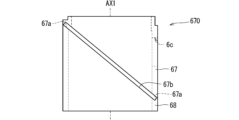
- FIG. 3 is a diagram schematically showing a first example of the configuration of a filter holder. It is a figure which shows schematically the 2nd example of a structure of a filter holder.
- FIG. 1 is a schematic cross-sectional view of an example of the configuration of a lighting device according to a first embodiment.
- FIG. 2 is a cross-sectional view schematically showing an example of a light path in the lighting device according to the first embodiment.
- FIG. 2 is an enlarged cross-sectional view showing a
- FIG. 2 is a cross-sectional view schematically showing an example of the configuration of a lighting device according to a second embodiment.
- FIG. 7 is a diagram schematically showing an example of the configuration of an optical system of a lighting device according to a third embodiment.
- FIG. 7 is a diagram schematically showing an example of the configuration of an optical system of a lighting device according to a fourth embodiment.
- the inventor has created a technology that can emit illumination light with higher efficiency in a lighting device.
- lighting devices 1 according to first to fourth embodiments will be described based on the drawings.
- FIG. 1 is a cross-sectional view schematically showing an example of the configuration of a lighting device 1 according to the first embodiment.
- FIG. 2 is a cross-sectional view schematically showing an example of a light path in the lighting device 1 according to the first embodiment.
- FIG. 3 is an enlarged sectional view showing a part of the configuration of the lighting device 1 of FIG. 1 in an enlarged manner. 1 to 3 show an example of the configuration of the illumination device 1 in a cross section including an optical axis AX1, which will be described later.
- the lighting device 1 is a device that emits fluorescence L1 as illumination light into an illumination space S1.
- the illumination space S1 is, for example, an indoor space of a building.
- the lighting device 1 is arranged, for example, on the ceiling of the lighting space S1.
- the illumination device 1 includes a light source 2, a wavelength conversion member 3, a wavelength separation filter 4, a lens optical system 5, and a housing 6.
- a light source 2 a wavelength conversion member 3
- a wavelength separation filter 4 a wavelength separation filter 4
- a lens optical system 5 a lens optical system 5
- a housing 6 a housing 6.
- the housing 6 houses the light source 2, the wavelength conversion member 3, the wavelength separation filter 4, and the lens optical system 5.
- the housing 6 has a first opening (hereinafter also referred to as an irradiation opening) 6a. Fluorescent light L1 as illumination light is emitted from the irradiation aperture 6a into the illumination space S1.
- the light source 2 has a light emitting section (for example, a light emitting surface) 21 that emits the excitation light L0.
- the excitation light L0 may be light having a peak within a wavelength range from 380 nm to 415 nm.
- the excitation light L0 may be purple light having a peak near 405 nm.
- the excitation light L0 is not necessarily limited to violet light, and may be, for example, blue light having a peak near 450 nm.
- the excitation light L0 from the light source 2 enters the wavelength separation filter 4.
- the wavelength separation filter 4 is located inside the housing 6 and guides the excitation light L0 to the wavelength conversion member 3.
- the wavelength conversion member 3 and the wavelength separation filter 4 are arranged along a direction (corresponding to a first direction) along the optical axis AX1, which will be described later, and the light source 2 and the wavelength separation filter 4 are , are lined up along a second direction intersecting the first direction.
- the wavelength separation filter 4 reflects the excitation light L0 from the light source 2 toward the wavelength conversion member 3.
- the lens optical system 5 includes one or more first lenses 51 located between the wavelength separation filter 4 and the wavelength conversion member 3 inside the housing 6.
- the first lens 51 is shown as a first A lens 51A and a first B lens 51B.
- the first A lens 51A is located on the wavelength conversion member 3 side with respect to the first B lens 51B.
- the excitation light L0 reflected by the wavelength separation filter 4 passes through the first B lens 51B and the first A lens 51A in this order, and enters the wavelength conversion member 3.
- the first A lens 51A and the first B lens 51B condense the excitation light L0 from the wavelength separation filter 4 onto the wavelength conversion member 3.
- first lenses 51 between the wavelength separation filter 4 and the wavelength conversion member 3 is not limited to two, and may be one, or may be three or more.
- the optical axis of the first A lens 51A is also referred to as the optical axis AX1
- the direction along the optical axis AX1 is also referred to as the optical axis direction.
- the wavelength conversion member 3 has, for example, a surface 3a, a surface 3b, and a side surface 3c.
- the surface 3b is the surface of the wavelength conversion member 3 on the first lens 51 side.
- the surface 3a is a surface of the wavelength conversion member 3 on the opposite side to the surface 3b.
- the side surface 3c is a side surface that connects the periphery of the surface 3a and the periphery of the surface 3b of the wavelength conversion member 3.
- the wavelength conversion member 3 may have a plate-like shape. That is, the surface 3a and the surface 3b of the wavelength conversion member 3 are substantially flat surfaces, and may be substantially parallel to each other.
- the wavelength conversion member 3 is positioned with its thickness direction along the optical axis direction. In the example of FIGS. 1 and 2, the surface 3a of the wavelength conversion member 3 is covered by the mounting member 64 of the housing 6. The attachment member 64 will be explained in detail later.
- the excitation light L0 that has passed through the first lens 51 is incident on the surface 3b of the wavelength conversion member 3.
- the wavelength conversion member 3 contains a phosphor, and emits fluorescence L1 having a spectrum different from the excitation light L0 based on the incident excitation light L0.
- the peak wavelength of the fluorescence L1 is longer than the peak wavelength of the excitation light L0, and the fluorescence L1 is visible light.
- the spread angle of the fluorescence L1 emitted from the wavelength conversion member 3 is large, for example, about 180 degrees.
- At least a portion of the fluorescence L1 from the wavelength conversion member 3 passes through the first lens 51 (here, the first A lens 51A and the first B lens 51B) and enters the wavelength separation filter 4.
- the first lens 51A and the first B lens 51B transmit the fluorescence L1 toward the effective surface of the wavelength separation filter 4.
- the effective surface here refers to the range in which the filter function of the wavelength separation filter 4 can be realized.
- the wavelength separation filter 4 guides the fluorescence L1 to the irradiation aperture 6a.
- the wavelength conversion member 3, wavelength separation filter 4, and irradiation aperture 6a are lined up in the optical axis direction. In this case, the wavelength separation filter 4 transmits the fluorescence L1 toward the irradiation aperture 6a.
- the lens optical system 5 may further include a second lens 52 located inside the housing 6 between the wavelength separation filter 4 and the irradiation aperture 6a.
- the first lens 51 and the second lens 52 are aligned on the optical axis.
- the fluorescence L1 from the wavelength separation filter 4 passes through the second lens 52 and is emitted into the illumination space S1 through the irradiation aperture 6a.
- one or more first lenses 51 are located between the wavelength separation filter 4 and the wavelength conversion member 3.
- This first lens 51 can narrow down the fluorescence L1 that travels from the wavelength conversion member 3 at a large spread angle.
- the first lens 51 can reduce the spread angle of the fluorescence L1.
- more fluorescence L1 can be guided to the wavelength separation filter 4 without increasing the size of the wavelength separation filter 4. That is, more of the fluorescence L1 out of the entire fluorescence L1 emitted by the wavelength conversion member 3 can be guided to the irradiation aperture 6a through the wavelength separation filter 4.
- the illumination device 1 can emit the fluorescence L1 into the illumination space S1 with higher efficiency.
- the lighting device 1 can emit the fluorescence L1 into the illumination space S1 with even higher efficiency.
- the excitation light L0 from the wavelength separation filter 4 passes through one or more first lenses 51 and enters the wavelength conversion member 3. Therefore, even if the distance between the wavelength conversion member 3 and the first A lens 51A is narrow, the excitation light L0 can appropriately enter the relatively wide surface 3b of the wavelength conversion member 3. Since the wavelength conversion member 3 can generate the fluorescence L1 over a wider range, it can generate the fluorescence L1 with a larger amount of light. As a result, the lighting device 1 can emit the fluorescent light L1 into the illumination space S1 with a larger amount of light.
- each configuration of the illumination device 1 will be roughly divided into the optical system and the housing 6 and explained.
- the optical system will be explained, and then the housing 6 will be explained.
- the light source 2 includes, for example, a semiconductor laser element such as a laser diode (LD), a light emitting element such as a VCSEL (Vertical Cavity Surface Emitting LASER), a light emitting diode (LED), and an SLD (super luminescent diode). May include.
- the emission part 21 of the light source 2 may be the emission end of the light emitting element.
- a gallium nitride (GaN)-based semiconductor laser that emits 405 nm violet laser light as excitation light L0 may be applied to the light emitting element.
- the light source 2 may further include a light guide member such as a fiber and a rod lens in addition to the light emitting element.
- the fiber includes a linear core and a cladding.
- the cladding has a lower refractive index than the core and covers the core.
- the excitation light L0 can be transmitted through the core while being totally reflected at the interface between the core and the cladding.
- the rod lens has, for example, a columnar shape. The excitation light L0 can be transmitted through the inside of the rod lens while being totally reflected on the side surface of the rod lens.
- the input end of such a light guide member corresponds to the first end face located at the longitudinal end of the fiber or the first end face located at the end of the rod lens
- the output end of the light guide member corresponds to the first end face located at the end of the fiber in the longitudinal direction. This corresponds to a second end surface on the opposite side to the end surface or a second end surface on the opposite side to the first end surface of the rod lens.
- Excitation light L0 from the light emitting element enters the input end of the light guide member, travels inside the light guide member, and exits from the output end of the light guide member.
- the output portion 21 of the light source 2 corresponds to the output end of the light guide member.
- the light source 2 may emit excitation light L0 having linear polarization.
- the polarization of the excitation light L0 may be, for example, s-polarized light with respect to the incident surface of the wavelength separation filter 4.
- various lenses may be located between the light source 2 and the wavelength separation filter 4.
- Wavelength separation filter 4 guides the excitation light L0 from the light source 2 to the wavelength conversion member 3, and guides the fluorescence L1 from the wavelength conversion member 3 to the irradiation aperture 6a.
- the wavelength separation filter 4 reflects the excitation light L0 toward the wavelength conversion member 3, and transmits the fluorescence L1 toward the irradiation aperture 6a.
- the wavelength separation filter 4 is also called, for example, a dichroic mirror or a dichroic film.
- the wavelength separation filter 4 may include a base material 41 and a dielectric multilayer film 42.
- the base material 41 is, for example, a transparent member containing at least one of glass such as optical glass and resin such as acrylic resin, and may have a flat plate shape.
- the dielectric multilayer film 42 is located, for example, on the first surface 4a or the second surface 4b of the base material 41.
- the dielectric multilayer film 42 has, for example, a structure in which dielectric thin films are repeatedly stacked multiple times.
- dielectric materials examples include silicon oxide (SiO 2 ), titanium oxide (TiO 2 ), aluminum oxide (Al 2 O 3 ), zirconium oxide (ZrO 2 ), tantalum oxide (Ta 2 O 5 ), and niobium oxide (Nb 2 O 3 ) are applied.
- a spectral transmittance that reflects the excitation light L0 and transmits the fluorescence L1 in the dielectric multilayer film 42 can be achieved.
- the wavelength separation filter 4 has a dielectric multilayer film for separating wavelengths on the first surface 4a, and may have an antireflection film on the second surface 4b. This can reduce the possibility that the amount of light will decrease due to absorption by the base material 41 of the wavelength separation filter 4, compared to the case where the dielectric multilayer film is located on the second surface 4b.
- FIG. 4 is a graph showing an example of the spectral transmittance of the wavelength separation filter 4.
- FIG. 4 shows the transmittance Ts of the wavelength separation filter 4 for s-polarized light and the transmittance Tn of the wavelength separation filter 4 for non-polarized light.
- the polarization state of the excitation light L0 is s-polarized light, and its wavelength is 405 nm.
- the transmittance Ts of the excitation light L0 is almost zero, so the excitation light L0 hardly passes through the wavelength separation filter 4.
- the absorption rate of the wavelength separation filter 4 is approximately zero, the excitation light L0 is reflected by the wavelength separation filter 4 with a reflection rate of approximately 100%.
- the polarization state of the fluorescence L1 is non-polarized.
- the transmittance Tn in the wavelength range of 450 nm or more is approximately 100%, so the fluorescence L1 having a wavelength of 450 nm or more is transmitted through the wavelength separation filter 4 at approximately 100%.
- the reflectance of the wavelength separation filter 4 for the excitation light L0 (for example, the reflectance when the wavelength is 420 nm or less) may be, for example, 80% or more, 90% or more, or 95%. It may be more than that.
- the transmittance Tn of the wavelength separation filter 4 for the fluorescence L1 (for example, the transmittance Tn when the wavelength is 450 nm or more) may be, for example, 80% or more, 90% or more, and 95% or more. % or more.
- the wavelength separation filter 4 reflects the excitation light L0 and transmits the fluorescence L1.
- the wavelength separation filter 4 is positioned such that its thickness direction intersects the optical axis AX1 of the first lens 51 at an angle close to about 45 degrees.
- the emission direction of the excitation light L0 from the light source 2 intersects the surface of the dielectric multilayer film 42 of the wavelength separation filter 4 at an angle close to 45 degrees. Thereby, the excitation light L0 from the light source 2 can be reflected toward the wavelength conversion member 3.
- a specific example of the attitude of the wavelength separation filter 4 and the emission direction of the excitation light L0 will be described later.
- the first lens 51 (here, the first A lens 51A and the first B lens 51B) may be a biconvex lens, for example.
- the first lens 51 is formed of a material containing at least one of glass such as optical glass and resin such as acrylic resin.
- the first A lens 51A and the first B lens 51B condense the excitation light L0 from the wavelength separation filter 4 onto the wavelength conversion member 3.
- the degree of spread of the excitation light L0 becomes smaller.
- FIG. 1 the degree of spread of the excitation light L0 becomes smaller.
- the size of the cross section of the excitation light L0 transmitted through the first B lens 51B perpendicular to the optical axis AX1 becomes smaller as it travels toward the wavelength conversion member 3. In other words, the excitation light L0 travels toward the wavelength conversion member 3 while becoming narrower.
- the first A lens 51A and the first B lens 51B may make the excitation light L0 incident on a part of the surface 3b of the wavelength conversion member 3, or may make it incident on the entire surface 3b of the wavelength conversion member 3.
- the wavelength conversion member 3 emits fluorescence L1 based on the excitation light L0.
- the first A lens 51A and the first B lens 51B transmit the fluorescence L1 from the wavelength conversion member 3 toward the effective surface of the wavelength separation filter 4.
- the degree of spread of the fluorescence L1 becomes smaller.
- the cross-sectional size of the fluorescent light L1 transmitted through the first B lens 51B decreases once toward the second lens 52, and then increases after passing through the waist portion BW.
- the waist portion BW is a portion where the cross section of the fluorescence L1 is the smallest between the first B lens 51B and the second lens 52.
- the waist portion BW may be located at a position overlapping the central portion of the wavelength separation filter 4 in the optical axis direction.
- the one or more first lenses 51 may be designed such that the waist portion BW overlaps the center portion of the wavelength separation filter 4 in the optical axis direction.
- the one or more first lenses 51 have the function of condensing the excitation light L0 from the wavelength separation filter 4 onto the wavelength conversion member 3, and the function of focusing the fluorescence L1 from the wavelength conversion member 3 on the wavelength separation filter 4. It has the function of transmitting light toward the surface.
- the wavelength conversion member 3 contains phosphor.
- the wavelength conversion member 3 is made of, for example, BaMgAl 10 O 17 :Eu or (Sr, Ca, Ba) 10 (PO 4 ) as a wavelength conversion material (that is, a fluorescent material) that converts the excitation light L0 into blue light. 6 Cl 2 :Eu, (Sr, Ba) 10 (PO 4 ) 6 Cl 2 :Eu, etc. may be included.
- the wavelength conversion member 3 is a wavelength conversion material that converts the excitation light L0 into blue-green light, such as (Sr, Ba, Ca) 5 (PO 4 ) 3 Cl:Eu, Sr 4 Al 14 O 25 :Eu, etc. may include.
- the wavelength conversion member 3 is made of, for example, SrSi 2 (O, Cl) 2 N 2 :Eu, (Sr, Ba, Mg) 2 SiO 4 :Eu 2+ , as a wavelength conversion material that converts the excitation light L0 into green light.
- SrSi 2 (O, Cl) 2 N 2 :Eu, (Sr, Ba, Mg) 2 SiO 4 :Eu 2+ as a wavelength conversion material that converts the excitation light L0 into green light.
- ZnS:Cu, Al, Zn 2 SiO 4 :Mn, etc. may be included.
- the wavelength conversion member 3 is a wavelength conversion material that converts the excitation light L0 into red light, such as Y 2 O 2 S:Eu, Y 2 O 3 :Eu, SrCaClAlSiN 3 :Eu 2+ , CaAlSiN 3 :Eu, or , CaAlSi(ON) 3 :Eu, and the like.
- the wavelength conversion member 3 may include 3Ga 5 O 12 :Cr or the like as a wavelength conversion material that converts the excitation light L0 into light having a wavelength in the near-infrared region. If the wavelength conversion member 3 includes multiple types of wavelength conversion materials corresponding to multiple colors of light, the wavelength conversion member 3 can emit fluorescence L1 with high color rendering properties.
- the excitation light L0 is light having a peak from 380 nm to 415 nm and the wavelength conversion member 3 has a phosphor corresponding to red, green, and blue light
- the color rendering property of the fluorescence L1 is can be increased.
- the wavelength conversion member 3 may contain a resin such as a binder for connecting the fine particles of the phosphor to each other.
- the size of the wavelength conversion member 3 viewed along the optical axis AX1 may be set smaller than the size of the first A lens 51A.
- the size of the first A lens 51A may be set larger than the size of the wavelength conversion member 3.
- the diameter of the wavelength conversion member 3 may be shorter than the diameter of the first A lens 51A.
- the diameter of the wavelength conversion member 3 may be set to about 2 mm to 4 mm.
- the diagonal of the wavelength conversion member 3 may be set to about 2 mm to 4 mm.
- the diameter or diagonal of the first A lens 51A may be set, for example, to about 4 mm to 15 mm.
- the fluorescence L1 from the wavelength conversion member 3 can be made to enter the first A lens 51A over a wider range.
- the distance between the wavelength conversion member 3 and the first A lens 51A may be narrower than the distance between the first A lens 51A and the first B lens 51B.
- the distance between the wavelength conversion member 3 and the first A lens 51A is set, for example, to about 1 mm or less, and the distance between the first A lens 51A and the first B lens 51B is set, for example, to about 2 mm or more.
- Lens optical system 5 (second lens 52)>
- the second lens 52 may be a convex lens, for example.
- the second lens 52 is located between the wavelength separation filter 4 and the irradiation aperture 6a.
- the second lens 52 focuses the fluorescence L1 from the wavelength separation filter 4 on the irradiation aperture 6a side.
- the number of second lenses 52 located between the wavelength separation filter 4 and the irradiation aperture 6a is not limited to one, and may be two or more.
- the lens optical system 5 may be an imaging optical system that forms an image of the wavelength conversion member 3 on the virtual image surface IS1. That is, in the example of FIGS. 1 and 2, the first A lens 51A, the first B lens 51B, and the second lens 52 constitute the imaging optical system.
- the wavelength conversion member 3 has a conjugate relationship with the image plane IS1. Note that the conjugate relationship here does not have a strict meaning, but rather refers to the area where the fluorescence L1 is most concentrated on the irradiation aperture 6a side from the wavelength conversion member 3 (the size of the fluorescence L1 in the cross section perpendicular to the optical axis AX1 is (the smallest portion) can be regarded as the image plane IS1.
- the image plane IS1 may be located at the irradiation aperture 6a, for example.
- the image surface IS1 may be a flat surface or a curved surface.
- the fluorescence L1 is focused on the image plane IS1 and is emitted into the illumination space S1 through the illumination aperture 6a.
- the image plane IS1 does not necessarily need to be located inside the irradiation aperture 6a.
- the image plane IS1 may be located at the boundary between the internal space of the irradiation aperture 6a and the internal space of the housing 6, as shown in FIG. Alternatively, the image plane IS1 may be located slightly shifted from the boundary toward the inner space of the housing 6. Alternatively, the image plane IS1 may be located at the boundary between the interior space of the irradiation aperture 6a and the illumination space S1, or may be located slightly shifted from the boundary toward the illumination space S1.
- M3/M1 the size of the fluorescence L1 in the wavelength conversion member 3
- the size M3 of the irradiation aperture 6a is the minimum value of the opening area of the irradiation aperture 6a viewed along the optical axis direction.
- the irradiation aperture 6a When the irradiation aperture 6a has a circular shape when viewed along the axial direction, its diameter may be set to about 5 mm to 15 mm, for example. When the irradiation aperture 6a has a rectangular shape when viewed along the axial direction, the diagonal thereof may be set to, for example, about 5 mm to 15 mm.
- the imaging magnification is the ratio of the size M2 of the fluorescence L1 on the image plane IS1 to the size M1 of the fluorescence L1 on the surface 3b of the wavelength conversion member 3.
- the size of the fluorescence L1 may be defined by a contour line having a light amount e 1/2 of the peak value in the light amount distribution of the fluorescence L1 in a cross section perpendicular to the optical axis AX1.
- e is called Napier's number.
- the light rays on both sides of the fluorescence L1 in FIG. 2 may be light rays having a light intensity that is e 1/2 of the peak value of the light intensity distribution in a cross section perpendicular to the optical axis AX1.
- Light in a region outside the region surrounded by the above contour lines that is, both outer rays
- the size M2 of the fluorescence L1 on the image plane IS1 can be made equal to or less than the size M3 of the irradiation aperture 6a. Therefore, it is possible to reduce the possibility that the fluorescence L1 will enter the peripheral portion of the irradiation opening 6a of the housing 6. Thereby, unnecessary reflected and scattered light leaking from the irradiation aperture 6a can be reduced.
- the imaging magnification of the lens optical system 5 may be set so that the size of the fluorescence L1 passing through the irradiation aperture 6a is smaller than that of the irradiation aperture 6a. According to this, reflected and scattered light can be further reduced.
- the spread angle ⁇ 2 of the fluorescence L1 in the illumination space S1 is smaller than the spread angle ⁇ 1 of the fluorescence L1 incident on the lens optical system 5.
- the lens optical system 5 is designed so that the spread angle ⁇ 2 is smaller than the spread angle ⁇ 1.
- the spread angle ⁇ 1 can be said to be the spread angle of the fluorescence L1 immediately before the lens optical system 5, and the spread angle ⁇ 2 can be said to be the spread angle of the fluorescence L1 immediately after the image plane IS1.
- the orientation angle (eg, half-power angle) of the fluorescence L1 in the illumination space S1 is about 60 degrees or less.
- the orientation angle of the lighting device 1 may be less than 45 degrees, less than 30 degrees or less than 15 degrees, for example.
- the refractive power of the first A lens 51A located immediately after the wavelength conversion member 3 may be larger than the refractive power of the first B lens 51B and the refractive power of the second lens 52. .
- the first A lens 51A can significantly reduce the degree of spread of the fluorescence L1 at the position closest to the wavelength conversion member 3.
- FIG. 1 the refractive power of the first A lens 51A located immediately after the wavelength conversion member 3 may be larger than the refractive power of the first B lens 51B and the refractive power of the second lens 52.
- the fluorescence L1 immediately after the first A lens 51A spreads as it advances toward the first B lens 51B, its spread angle is smaller than the spread angle ⁇ 1 of the fluorescence L1 incident on the first A lens 51A. significantly smaller. Therefore, the size of the first B lens 51B in the width direction perpendicular to the optical axis AX1 can be reduced. In other words, even if the size of the first B lens 51B is reduced, the fluorescence L1 from the first A lens 51A can be appropriately made to enter the first B lens 51B. As a result, the size of the lighting device 1 in the width direction can be reduced.
- the first A lens 51A has a first surface 51Aa and a second surface 51Ab
- the first B lens 51B has a first surface 51Ba and a second surface 51Bb.
- the first surface 51Aa is the surface of the first A lens 51A on the wavelength conversion member 3 side
- the second surface 51Ab is the surface of the first A lens 51A on the wavelength separation filter 4 side.
- the first surface 51Ba is the surface of the first B lens 51B on the wavelength conversion member 3 side
- the second surface 51Bb is the surface of the first B lens 51B on the wavelength separation filter 4 side.
- the first surface 51Aa of the first A lens 51A may be curved so as to be convex toward the wavelength conversion member 3 side, and the second surface 51Ab may be convex toward the wavelength separation filter 4 side. It may be curved so that The first surface 51Aa and the second surface 51Ab of the first A lens 51A may be curved surfaces without steps. In other words, the first A lens 51A does not have to be a Fresnel lens. Thereby, scattering or reflection at the first A lens 51A can be reduced. As a result, a comfortable illumination space S1 with less glare can be realized. Further, the curvature of the first surface 51Aa of the first A lens 51A may be smaller than the curvature of the second surface 51Ab.
- the first surface 51Aa may be flatter than the second surface 51Ab. According to this, the fluorescence L1 from the wavelength conversion member 3 can be incident on the first surface 51Aa of the first A lens 51A over a wider range. In other words, it is possible to increase the proportion of the fluorescence L1 that is incident on the first surface 51Aa of the first A lens 51A among the entire fluorescence L1 emitted by the wavelength conversion member 3, and as a result, the proportion of the fluorescence L1 that is emitted from the irradiation aperture 6a is increased. The proportion can be increased. Therefore, the lighting device 1 can emit the fluorescent light L1 into the illumination space S1 with higher efficiency.
- the curvature of the second surface 51Ab of the first A lens 51A may be larger than the curvature of the first surface 51Aa. If the curvature of the second surface 51Ab is large, the refractive power of the first A lens 51A can be improved. Therefore, the first A lens 51A can significantly reduce the spread angle of the fluorescence L1. Therefore, the size of the lighting device 1 in the width direction can be reduced.
- the first surface 51Ba of the first B lens 51B may be curved so as to be convex toward the wavelength conversion member 3 side, and the second surface 51Bb may be convex toward the wavelength separation filter 4 side. It may be curved so that The first surface 51Ba and the second surface 51Bb of the first B lens 51B may be curved surfaces without steps. In other words, the first B lens 51B does not have to be a Fresnel lens. Thereby, a comfortable illumination space S1 with less glare can be realized.
- the curvature of the first surface 51Aa of the first A lens 51A may be smaller than the curvature of both the first surface 51Ba and second surface 51Bb of the first B lens 51B.
- the curvature of the second surface 51Ab of the first A lens 51A may be larger than the curvature of both the first surface 51Ba and the second surface 51Bb of the first B lens 51B.
- the first lens 51 closest to the wavelength conversion member 3 may have the largest refractive power. Thereby, the first lens 51 closest to the wavelength conversion member 3 can significantly reduce the spread angle of the fluorescence L1. Therefore, the size of the lighting device 1 in the width direction can be effectively reduced.
- the curvature of the second surface 51Ab of the first A lens 51A is very large. If the size in the width direction of the first A lens 51A having the second surface 51Ab with such a large curvature is increased, it becomes difficult to manufacture the first A lens 51A. Furthermore, the size of the first A lens 51A along the optical axis AX1 also increases, leading to an increase in the size of the lighting device 1.
- the size of the first A lens 51A may be smaller than the first B lens 51B. That is, the area of the first A lens 51A viewed along the optical axis AX1 may be smaller than the area of the first B lens 51B. According to this, the first A lens 51A can be easily manufactured, and the size of the illumination device 1 in the optical axis direction can also be reduced.
- the first surface 52a of the second lens 52 on the wavelength separation filter 4 side and the second surface 52b on the irradiation aperture 6a side are on the wavelength separation filter 4 side and the irradiation aperture 6a side, respectively. It may be curved in a convex manner.
- the first surface 52a and the second surface 52b of the second lens 52 may be curved surfaces without steps. In other words, the second lens 52 does not need to be a Fresnel lens. This makes it possible to create a comfortable lighting space with less glare.
- the curvature of the first surface 52a of the second lens 52 may be smaller than the curvature of the second surface 52b.
- the spectral transmittance and spectral reflectance of the dielectric multilayer film 42 have incidence angle dependence. Specifically, a wavelength shift may occur in the spectral transmittance and the spectral reflectance depending on the incident angle. That is, as the incident angle deviates from a predetermined incident angle, the spectral transmittance in FIG. 4 can shift along the horizontal axis direction. In the example of FIG. 4, the transmittance Ts shifted in the horizontal axis direction is shown by a two-dot chain line. Although not shown, the transmittance Tn can also be shifted like the transmittance Ts.
- the excitation light L0 enters the wavelength separation filter 4 while spreading. Therefore, each beam of the excitation light L0 enters the wavelength separation filter 4 at different incident angles. That is, there are rays of excitation light L0 that enter the wavelength separation filter 4 at an incident angle other than the predetermined incident angle.
- the predetermined angle of incidence here is, for example, the angle between the optical axis AX2 of the light source 2 and the normal to the wavelength separation filter 4.
- Each light beam of the fluorescent light L1 may also enter the wavelength separation filter 4 at mutually different incident angles. That is, there are rays of fluorescence L1 that enter the wavelength separation filter 4 at an incident angle other than the predetermined incident angle.
- the predetermined angle of incidence here is the angle between the optical axis AX1 and the normal to the wavelength separation filter 4.
- each ray of the excitation light L0 may enter the wavelength separation filter 4 at different angles of incidence, and each ray of the fluorescence L1 may also enter the wavelength separation filter 4 at different angles of incidence. Therefore, both the excitation light L0 and the fluorescence L1 can be affected by the incident angle dependence of the dielectric multilayer film 42.
- the greater the dependence of the dielectric multilayer film 42 on the incident angle that is, the greater the shift amount of the spectral transmittance and the spectral reflectance with respect to the amount of deviation in the incident angle, the greater the influence on the excitation light L0 and the fluorescence L1.
- the first surface 4a of the dielectric multilayer film 42 on the opposite side from the base material 41 is exposed inside the casing 6. That is, the first surface 4a of the dielectric multilayer film 42 is in contact with the air inside the casing 6. According to this, the incident angle dependence of the dielectric multilayer film 42 can be reduced compared to a structure in which the first surface 4a of the dielectric multilayer film 42 is covered with a member having a higher refractive index than air. can.
- the excitation light L0 can be reflected by the wavelength separation filter 4 with a spectral reflectance closer to a predetermined spectral reflectance, and the fluorescence L1 can be transmitted through the wavelength separation filter 4 with a spectral transmittance closer to a predetermined spectral transmittance. be able to.
- the first lens 51 may shape the fluorescent light L1 so that the plurality of light beams of the fluorescent light L1 are incident on the wavelength separation filter 4 with smaller variations in the incident angle.
- the refractive power of the first lens 51 is designed so that the variation in the incident angle of the fluorescent light L1 incident on the wavelength separation filter 4 is smaller than the variation in the incident angle of the fluorescent light L1 incident on the first A lens 51A. good.
- the refractive power of the first lens 51 is designed so that the fluorescence L1 immediately after the first B lens 51B is closer to parallel light than the fluorescence L1 immediately before the first A lens 51A. Good too. According to this, it is possible to increase the proportion of the fluorescence L1 that passes through the wavelength separation filter 4 with a spectral transmittance closer to a predetermined spectral transmittance.
- the second lens 52 is not necessarily required.
- the refractive power of the first lens 51 needs to be increased in order for the illumination device 1 to emit the fluorescent light L1 with the same spread angle ⁇ 2.
- the refractive power of the first lens 51 is increased, the variation in the incident angle of the fluorescence L1 entering the wavelength separation filter 4 increases.
- the excitation light L0 also passes through the first lens 51. Therefore, in order to irradiate the wavelength conversion member 3 with the excitation light L0 in an appropriate range, it is necessary to increase the spread angle of the excitation light L0 that enters the first lens 51. Consequently, the excitation light L0 needs to be made incident on the wavelength separation filter 4 at a large spread angle. In this case, the variation in the angle of incidence on the wavelength separation filter 4 for each ray of the excitation light L0 also increases. Since the spectral reflectance of the dielectric multilayer film 42 of the wavelength separation filter 4 has incidence angle dependence, if the variation in the angle of incidence of incidence on the wavelength separation filter 4 increases, the spectral reflectance will deviate greatly from the predetermined spectral reflectance. The proportion of the excitation light L0 reflected by the spectral reflectance increases.
- the refractive power of the first lens 51 can be reduced, so that the excitation light L0 and the fluorescence L1 can be transmitted to the wavelength separation filter 4 with a relatively small spread angle. It can be input to Therefore, it is possible to increase the proportion of the excitation light L0 reflected by the wavelength separation filter 4 with a predetermined spectral reflectance, and it is possible to increase the proportion of the fluorescence L1 that passes through the wavelength separation filter 4 with a predetermined spectral transmittance. can.
- the angle ⁇ 1 formed between the wavelength separation filter 4 and the optical axis direction will be explained. It can also be said that the angle ⁇ 1 is an angle of 90 degrees or less between a straight line parallel to the first surface 4a of the dielectric multilayer film 42 and the optical axis AX1.
- the angle ⁇ 1 may be 45 degrees or more. More specifically, the angle ⁇ 1 may be greater than 45 degrees and less than or equal to 67.5 degrees. Alternatively, the angle ⁇ 1 may be greater than or equal to 46 degrees and less than or equal to 67.5 degrees. As a more specific example, the angle ⁇ 1 may be about 50 degrees.
- the size of the wavelength separation filter 4 in the optical axis direction can be reduced.
- the size of the wavelength separation filter 4 in the optical axis direction can be effectively reduced by setting the angle ⁇ 1 larger than 45 degrees. Can be done. As a result, the size of the lighting device 1 in the optical axis direction can be reduced.
- the lighting device 1 when the lighting device 1 is installed in a space under the ceiling, the lighting device 1 is installed with the optical axis direction along the vertical direction.
- the height of the space under the attic may be low.
- the height of the space under the ceiling may be about 10 cm.
- the angle ⁇ 1 As described above, by setting the angle ⁇ 1 to be larger than 45 degrees, the size of the lighting device 1 in the optical axis direction can be reduced. Therefore, the lighting device 1 can be easily installed even in a low-height space under the ceiling.
- the distance between the first B lens 51B and the second lens 52 becomes wider, it becomes difficult to increase the spread angle ⁇ 2 in the optical design of the lens optical system 5.
- the distance between the first B lens 51B and the second lens 52 can be further narrowed. . Therefore, the optical design of the lens optical system 5 for increasing the divergence angle ⁇ 2 can be facilitated.
- Angle ⁇ 2 is an angle adjacent to angle ⁇ 1. It can also be said that the angle ⁇ 2 is an angle formed by a first direction in which the wavelength conversion member 3, the wavelength separation filter 4, and the irradiation aperture 6a are lined up, and a second direction in which the light source 2 and the wavelength separation filter 4 are lined up.
- the angle ⁇ 2 may be greater than or equal to 45 degrees and less than 90 degrees. Alternatively, the angle ⁇ 2 may be greater than or equal to 45 degrees and less than or equal to 88 degrees. In this case, as shown in FIG.
- the optical axis AX2 is inclined with respect to the width direction perpendicular to the optical axis AX1. Specifically, the optical axis AX2 is inclined so that it approaches the light source 2 in the width direction from the wavelength separation filter 4 and approaches the wavelength conversion member 3 in the optical axis direction.
- a light ray that travels from the light source 2 through the center of the excitation light L0 along the optical axis AX2 is reflected by the wavelength separation filter 4, and travels toward the wavelength conversion member 3 along the optical axis AX1.
- the light can be incident substantially perpendicularly to the surface 3b of the photo frame 3. Therefore, the excitation light L0 can be made to enter the surface 3b of the wavelength conversion member 3 evenly around the optical axis AX1.
- the housing 6 may include a first housing section 61 and a second housing section 62.
- the first housing section 61 houses the wavelength conversion member 3, the wavelength separation filter 4, and the lens optical system 5, and the second housing section 62 houses the light source 2.
- the first housing section 61 may include a main body section 63, a mounting member 64, and a decorative frame section 65.
- the main body portion 63 is a member that houses the wavelength separation filter 4 and the lens optical system 5.
- the main body portion 63 may include an opening member 631 and a side wall 632.
- the side wall 632 has, for example, a cylindrical shape surrounding the optical axis AX1.
- the side wall 632 may have a cylindrical shape, for example.
- the side wall 632 may be a single piece, or may be a composite body made up of a plurality of members.
- the first A lens 51A, the first B lens 51B, the wavelength separation filter 4, and the second lens 52 are located in this order in the optical axis direction.
- the aperture member 631 has, for example, a plate-like shape, and is positioned such that its thickness direction is along the optical axis direction.
- the peripheral edge of the opening member 631 is connected to the edge of the side wall 632 on the wavelength conversion member 3 side.
- a second aperture (hereinafter simply referred to as an aperture) 6b is formed in the center of the aperture member 631, passing through the aperture member 631 in the optical axis direction.
- the attachment member 64 may be attached to the opening member 631 with the opening 6b of the opening member 631 closed.
- the mounting member 64 has, for example, a plate-like shape, and is positioned such that its thickness direction is along the optical axis direction. As shown in FIG. 1, the attachment member 64 may be attached to the surface 631a of the aperture member 631 on the side opposite to the wavelength separation filter 4.
- the attachment member 64 may be attached to the opening member 631, for example, by any attachment method. As an example of a specific attachment method, the attachment member 64 may be attached to the opening member 631 using a fixing agent such as an adhesive. Since the attachment member 64 closes the opening 6b, it can also be said to be a lid member.
- the mounting member 64 has a surface 64a, a surface 64b, and a side surface 64c.
- the surface 64b is the surface of the mounting member 64 on the opening member 631 side. A part of the outer peripheral side of the surface 64b of the mounting member 64 is in contact with the surface 631a of the opening member 631 while facing the surface 631a in the optical axis direction.
- the surface 64a is the opposite surface of the mounting member 64 from the surface 64b.
- the side surface 64c is a side surface that connects the peripheral edge of the surface 64a and the peripheral edge of the surface 64b of the mounting member 64.
- the wavelength conversion member 3 may be located on the surface 64b of the mounting member 64.
- the wavelength conversion member 3 is located on a region of the surface 64b of the mounting member 64 that faces the opening 6b of the aperture member 631 in the optical axis direction.
- a recessed portion filled with the wavelength conversion member 3 may be formed in the surface 64b of the attachment member 64.
- the wavelength conversion member 3 may be joined to the mounting member 64, for example.
- the attachment member 64 can function as a support that supports the wavelength conversion member 3.
- the area of the surface 3b of the wavelength conversion member 3 viewed along the optical axis direction may be smaller than the minimum value of the opening area of the opening 6b of the aperture member 631. According to this, a larger portion of the fluorescent light L1 that spreads and travels from the wavelength conversion member 3 can pass through the opening 6b. Further, as shown in FIG. 1, the surface 3b of the wavelength conversion member 3 may be flush with the surface 631a of the aperture member 631. Note that the surface 3b of the wavelength conversion member 3 may be located inside the opening 6b of the aperture member 631, or may be located outside the opening 6b.
- the first A lens 51A may be located in the aperture 6b of the aperture member 631.
- the aperture 6b of the aperture member 631 may be composed of a diaphragm aperture 6ba and a storage aperture 6bb.
- the storage opening 6bb is a space in which the first A lens 51A is stored, and is located on the first B lens 51B side with respect to the aperture aperture 6ba.
- the aperture aperture 6ba communicates with the storage opening 6bb in the optical axis direction, and its opening area is smaller than the opening area of the storage opening 6bb.
- the inner peripheral surface forming the opening 6b of the opening member 631 has a stepped shape.
- the inner circumferential surface of the opening member 631 includes a first inner circumferential surface 633a that forms the aperture opening 6ba, a second inner circumferential surface 631b that forms the storage opening 6bb, and a first inner circumferential surface 633a and a second inner circumferential surface 631b that forms the storage opening 6bb. It has a connecting surface 633b that connects the two inner circumferential surfaces 631b.
- the first inner peripheral surface 633a is closer to the optical axis AX1 than the second inner peripheral surface 631b. Therefore, the opening area of the diaphragm opening 6ba is smaller than the opening area of the storage opening 6bb.
- the opening member 631 includes an inner peripheral protrusion 633.
- the inner peripheral protrusion 633 extends further toward the optical axis AX1 than the second inner peripheral surface 631b, and surrounds the optical axis AX1.
- the inner circumferential surface of this inner circumferential protrusion 633 corresponds to the first inner circumferential surface 633a, and the surface of the inner circumferential protrusion 633 on the first A lens 51A side corresponds to the connecting surface 633b.
- the second inner peripheral surface 631b of the aperture member 631 may be in contact with the side surface of the first A lens 51A.
- the side surface of the first A lens 51A is a surface that connects the periphery of the first surface 51Aa and the periphery of the second surface 51Ab.
- the first A lens 51A may fit into the storage opening 6bb of the opening member 631.
- the aperture 6b (specifically, the aperture 6ba) of the aperture member 631 allows the light of the fluorescence L1 having a predetermined spread angle ⁇ 1 or less to pass through to the lens optical system 5 side.
- the light hereinafter referred to as shielding light
- shielding light that travels at a spread angle larger than the spread angle ⁇ 1 of the fluorescent light L1 is blocked by the aperture member 631.
- the first inner circumferential surface 633a of the aperture aperture 6ba is inclined with respect to the optical axis AX1. Specifically, the first inner peripheral surface 633a is inclined such that the opening area of the aperture 6ba increases toward the wavelength conversion member 3 side. In other words, the first inner circumferential surface 633a of the aperture aperture 6ba is inclined so as to move away from the central axis of the aperture 6b (optical axis AX1 here) as it goes toward the wavelength conversion member 3 side. Since the wavelength conversion member 3 is located near the aperture 6ba, most of the shielded light from the wavelength conversion member 3 enters the first inner peripheral surface 633a of the aperture 6ba.
- the shielded light is reflected or scattered by the first inner circumferential surface 633a of the diaphragm aperture 6ba and proceeds to the side opposite to the first A lens 51A, or a portion thereof is absorbed by the aperture member 631.
- the fluorescence L1 whose spread angle is less than or equal to the predetermined spread angle ⁇ 1 passes through the diaphragm aperture 6ba, and the shielded light outside the aperture 6ba is blocked by the aperture member 631. shielded. Therefore, it is possible to reduce the possibility that unnecessary reflected and scattered light will be emitted from the irradiation aperture 6a. Therefore, a comfortable illumination space S1 with less glare can be realized.
- the opening member 631 may be a light-absorbing member.
- Light-absorbing means a member having an absorption rate of 60% or more in the visible light region.
- the first inner circumferential surface 633a of the opening member 631 may be a surface of a light-absorbing member.
- the absorption rate of the first inner circumferential surface 633a for the fluorescence L1 is high.
- the absorption rate of the first inner peripheral surface 633a may be, for example, 60% or more, 80% or more, or 90% or more.
- the first inner circumferential surface 633a may have a high absorption rate for the entire wavelength range of the fluorescence L1, or may have a high absorption rate for the peak wavelength.
- the first inner circumferential surface 633a is formed by, for example, performing a blackening process.
- blackening treatments such as chemical conversion treatment, plating, and painting can be employed as the blackening treatment.
- a dull blackening treatment or a glossy blackening treatment may be employed.
- the first inner circumferential surface 633a is made of a black material.
- the material includes, for example, at least one of a black metal, a black metal oxide film, and a black resin.
- the first inner circumferential surface 633a may be formed of a dielectric multilayer film.
- a dielectric multilayer film has, for example, a structure in which a plurality of dielectric thin films are stacked.
- the dielectric include one or more of titanium oxide (TiO 2 ), SiO 2 , niobium pentoxide (Nb 2 O 5 ), tantalum pentoxide (Ta 2 O 5 ), and magnesium fluoride (MgF 2 ). materials are used.
- Such a dielectric multilayer film may also be called a low reflection film or an antireflection film.
- the first A lens 51A is located at the aperture 6b of the aperture member 631 located immediately after the wavelength conversion member 3. Specifically, the first A lens 51A is located within the storage opening 6bb located immediately after the aperture aperture 6ba. Therefore, the distance between the wavelength conversion member 3 and the first A lens 51A can be narrowed. Therefore, most of the fluorescence L1 from the wavelength conversion member 3 can be made to enter the first A lens 51A.
- the casing 6 includes a first inner casing 66, a second inner casing 67, a third inner casing 68, and a fourth inner casing, all of which are located inside the first casing part 61. It may further include a housing 69.
- the first inner housing 66 can function together with the aperture member 631 as a lens holder for holding the first A lens 51A.
- the first inner housing 66 is located between the first A lens 51A and the first B lens 51B.
- the peripheral edge of the first A lens 51A is held between the inner peripheral protrusion 633 of the aperture member 631 and the first inner housing 66 in the optical axis direction. That is, the inner peripheral protrusion 633 of the opening member 631 is in contact with the peripheral edge of the first surface 51Aa of the first A lens 51A, and the first inner housing 66 is in contact with the peripheral edge of the second surface 51Ab of the first A lens 51A. ing.
- the first inner casing 66 may include a pressing member 661 and a side wall 662.
- the holding member 661 is located on the first B lens 51B side with respect to the opening member 631.
- the holding member 661 has a plate-like shape, and is positioned with its thickness direction along the optical axis direction.
- the holding member 661 faces the opening member 631 in the optical axis direction.
- the holding member 661 has an opening 66a formed in its center. The peripheral edge of the opening 66a of the holding member 661 is in contact with the second surface 51Ab of the first A lens 51A.
- the fluorescence L1 travels inside the first A lens 51A while spreading. Therefore, as shown in FIG. 3, the opening area of the opening 66a of the holding member 661 may be larger than the opening area of the aperture opening 6ba of the opening member 631. According to this, while the opening member 631 and the holding member 661 appropriately sandwich and hold the first A lens 51A, it is possible to more effectively allow the fluorescence L1 to pass through the opening 66a of the holding member.
- the inner peripheral surface of the holding member 661 forming the opening 66a may have a first inclined surface 661a and a second inclined surface 661b.
- the first inclined surface 661a is in contact with the second surface 51Ab of the first A lens 51A, and has a shape along the second surface 51Ab. Therefore, the first inclined surface 661a is inclined so as to move away from the optical axis AX1 as it approaches the wavelength conversion member 3 in the optical axis direction.
- the second inclined surface 661b is located on the first B lens 51B side with respect to the first inclined surface 661a. An edge of the second inclined surface 661b on the first inclined surface 661a side is connected to an edge of the first inclined surface 661a on the second inclined surface 661b side.
- the second inclined surface 661b is inclined on the opposite side to the first inclined surface 661a. That is, the second inclined surface 661b is inclined so as to approach the optical axis AX1 as it approaches the first inclined surface 661a in the optical axis direction. In other words, the second inclined surface 661b is inclined so as to move away from the optical axis AX1 as it approaches the wavelength separation filter 4.
- the opening area of the opening 66a can be increased while increasing the thickness of the pressing member 661. Therefore, the strength of the pressing member 661 can be improved while increasing the amount of fluorescent light L1 passing through the opening 66a.
- the second inclined surface 661b is inclined with respect to the optical axis AX1
- the fluorescence L1 transmitted through the first A lens 51A is difficult to enter the second inclined surface 661b. Therefore, unnecessary scattering and reflection of the fluorescence L1 can be reduced. Therefore, it is possible to reduce the possibility that unnecessary reflected and scattered light will be emitted from the irradiation aperture 6a.
- the side wall 662 of the first inner housing 66 has a cylindrical shape surrounding the optical axis AX1, and extends from the outer peripheral edge of the pressing member 661 toward the first B lens 51B side.
- the inner peripheral surface of the side wall 662 is located closer to the optical axis AX1 than the side surface of the first B lens 51B.
- the side surface of the first B lens 51B is a surface that connects the peripheral edge of the first surface 51Ba and the peripheral edge of the second surface 51Bb.
- the outer peripheral surface of the side wall 662 and the side surface of the first B lens 51B may be in contact with the inner peripheral surface of the side wall 632.
- the first B lens 51B may fit into the inner peripheral surface of the side wall 632.
- the edge of the side wall 662 on the first B lens 51B side may be in contact with the peripheral edge of the first surface 51Ba of the first B lens 51B.
- the first inner housing 66 can also function as a spacer that determines the distance between the first A lens 51A and the first B lens 51B.
- the second inner housing 67 can function together with the first inner housing 66 as a lens holder for holding the first B lens 51B. As shown in FIG. 1, the second inner housing 67 is located between the first B lens 51B and the wavelength separation filter 4.
- the second inner housing 67 has, for example, a cylindrical shape surrounding the optical axis AX1.
- the inner peripheral surface of the second inner housing 67 is located closer to the optical axis AX1 than the side surface of the first B lens 51B.
- the outer peripheral surface of the second inner housing 67 may be in contact with the inner peripheral surface of the side wall 632.
- the peripheral edge of the first B lens 51B is held between the first inner housing 66 and the second inner housing 67 in the optical axis direction.
- the edge of the first inner housing 66 on the first B lens 51B side is in contact with the peripheral edge of the first surface 51Ba of the first B lens 51B
- the edge of the first B lens of the second inner housing 67 is in contact with the peripheral edge of the first surface 51Ba of the first B lens 51B.
- the edge on the 51B side is in contact with the peripheral edge of the second surface 51Bb of the first B lens 51B.
- the edge of the second inner housing 67 on the wavelength separation filter 4 side may also be in contact with the peripheral edge of the wavelength separation filter 4.
- the second inner housing 67 can also function as a spacer that determines the distance between the first B lens 51B and the wavelength separation filter 4.
- the end surface of the second inner housing 67 that faces the wavelength separation filter 4 may have a shape along the first surface 4a of the wavelength separation filter 4, and the wavelength separation filter 4 may have a shape along the first surface 4a of the wavelength separation filter 4.
- the first surface 4a may be inclined to the same extent as the first surface 4a.
- a third opening (hereinafter referred to as an introduction opening) 6c may be formed in the side wall 632 of the first housing portion 61 and the second inner housing 67.
- the introduction opening 6c is an opening that allows the excitation light L0 from the light source 2 located outside the first housing part 61 to pass through and guides the excitation light L0 to the wavelength separation filter 4 inside the first housing part 61.
- the third inner housing 68 can function together with the second inner housing 67 as a filter holder 670 for holding the wavelength separation filter 4.
- the third inner housing 68 is located between the wavelength separation filter 4 and the second lens 52.
- the third inner housing 68 has, for example, a cylindrical shape surrounding the optical axis AX1.
- the inner peripheral surface of the third inner housing 68 is located closer to the optical axis AX1 than the peripheral edge of the wavelength separation filter 4.
- the outer peripheral surface of the third inner housing 68 may be in contact with the inner peripheral surface of the side wall 632.
- the peripheral edge of the wavelength separation filter 4 is held between the second inner housing 67 and the third inner housing 68 in the optical axis direction.
- the edge of the second inner housing 67 on the wavelength separation filter 4 side is in contact with the peripheral edge of the first surface 4a of the wavelength separation filter 4, and the edge of the wavelength separation filter 4 of the third inner housing 68 is in contact with the peripheral edge of the first surface 4a of the wavelength separation filter 4.
- the edge on the 4 side is in contact with the peripheral edge of the second surface 4b of the wavelength separation filter 4 on the opposite side to the first surface 4a.
- the end face of the third inner housing 68 facing the wavelength separation filter 4 has a shape along the peripheral edge of the second surface 4b of the wavelength separation filter 4, and the wavelength separation filter It may be inclined to the same extent as the second surface 4b of No. 4.
- An adhesive may be placed between the wavelength separation filter 4 and the second inner housing 67, and an adhesive may be placed between the wavelength separation filter 4 and the third inner housing 68. Often, an adhesive may be located between the wavelength separation filter 4 and the side wall 632.
- the edge of the third inner housing 68 on the second lens 52 side is in contact with the peripheral edge of the second lens 52. According to this, the third inner housing 68 can also function as a spacer that determines the distance between the wavelength separation filter 4 and the second lens 52.
- the fourth inner housing 69 can function as a lens holder that holds the second lens 52 together with the third inner housing 68.
- the fourth inner housing 69 is located between the second lens 52 and the decorative frame portion 65.
- the fourth inner housing 69 has, for example, a cylindrical shape surrounding the optical axis AX1.
- the inner peripheral surface of the fourth inner housing 69 is located closer to the optical axis AX1 than the side surface of the second lens 52.
- the side surface of the second lens 52 is a surface that connects the peripheral edge of the first surface 52a and the peripheral edge of the second surface 52b.
- the outer peripheral surface of the fourth inner housing 69 and the side surface of the second lens 52 may be in contact with the inner peripheral surface of the side wall 632.
- the second lens 52 may fit into the inner peripheral surface of the side wall 632.
- the peripheral edge of the second lens 52 is held between the third inner housing 68 and the fourth inner housing 69 in the optical axis direction. That is, the edge of the third inner housing 68 on the second lens 52 side is in contact with the peripheral edge of the first surface 52a of the second lens 52, and the second lens of the fourth inner housing 69 is in contact with the peripheral edge of the first surface 52a of the second lens 52.
- the edge on the 52 side is in contact with the peripheral edge of the second surface 52b of the second lens 52.
- the fourth inner housing 69 may be attached to the side wall 632, for example.
- the decorative frame portion 65 is attached to the end of the side wall 632 on the opposite side from the opening member 631.
- the decorative frame portion 65 may include a plate-like portion 651 and a cylindrical portion 652.
- the plate-like portion 651 has a plate-like shape, and is positioned with its thickness direction along the optical axis direction.
- the cylindrical portion 652 has a cylindrical shape extending from the periphery of the plate portion 651 toward the wavelength conversion member 3 along the optical axis direction, and is connected to, for example, an end portion of the side wall 632.
- An irradiation aperture 6a is formed in the center of the plate-like portion 651, passing through the plate-like portion 651 in the optical axis direction.
- the diameter of the irradiation opening 6a is smaller than the inner diameter of the fourth inner housing 69, for example.
- the structure consisting of the main body part 63 and the decorative frame part 65 may be constituted by a plurality of structural members as appropriate.
- the structure may be divided into a plurality of constituent members in the optical axis direction. The structure may be assembled by attaching these plurality of components to each other.
- the inner circumferential surface 651a forming the illumination opening 6a of the decorative frame portion 65 may be inclined such that the opening area increases as it approaches the illumination space S1 in the optical axis direction. .
- the inner circumferential surface 651a may be inclined so as to move away from the central axis of the irradiation aperture 6a as it approaches the illumination space S1.
- the second housing section 62 is a member that houses the light source 2.
- the second housing section 62 is attached to the side of the first housing section 61.
- the second housing portion 62 may include a bottom member 621 and a side wall 622.
- a light source 2 is attached to the bottom member 621.
- the side wall 622 has a cylindrical shape extending from the periphery of the bottom member 621 along the optical axis AX2. The edge of the side wall 622 on the opposite side from the light source 2 is connected to the side wall 632 of the first housing section 61 in a state surrounding the introduction opening 6c.
- first housing part 61 and the second housing part 62 there may be a gap between the first housing part 61 and the second housing part 62. Thereby, heat transfer between the first housing part 61 and the second housing part 62 can be inhibited. Therefore, heat can easily escape from the first housing section 61 and the second housing section 62 to the outside. As a result, heat dissipation from the lighting device 1 can be improved.
- the thermal conductivity of the attachment member 64 may be higher than that of the wavelength conversion member 3.
- the material of the mounting member 64 may be a metal material with high thermal conductivity.
- This metal material includes, for example, copper (Cu), aluminum (Al), magnesium (Mg), gold (Au), silver (Ag), iron (Fe), chromium (Cr), cobalt (Co), beryllium ( Applicable materials include Be), molybdenum (Mo), tungsten (W), and alloys.
- the wavelength conversion member 3 can be cooled from the surface 3a side by the mounting member 64.
- the surface 3a of the wavelength conversion member 3 is directly bonded to the surface 64b of the mounting member 64.
- the surface 3a of the wavelength conversion member 3 and the surface 64b of the mounting member 64 can be directly joined. If the attachment member 64 is directly joined to the wavelength conversion member 3, the heat of the wavelength conversion member 3 can be transferred to the attachment member 64 more quickly.
- Such a mounting member 64 can function as a so-called heat sink. Thereby, the extent to which the wavelength conversion member 3 deteriorates due to heat can be reduced.
- the side surface 3c of the wavelength conversion member 3 may also be joined to the attachment member 64. According to this, the heat of the wavelength conversion member 3 can also be transmitted to the attachment member 64 from the side surface 3c. Therefore, the cooling efficiency of the mounting member 64 can be improved.
- the surface 64b of the mounting member 64 may have reflectivity for the fluorescence L1. Reflectivity here means, for example, that the reflectance is high in at least a part of the wavelength range of the fluorescence L1.
- the reflectance may be, for example, 60% or more, 80% or more, or 90% or more. According to this, the fluorescence L1 generated in the wavelength conversion member 3 and directed toward the attachment member 64 is reflected by the surface 64b of the attachment member 64, and proceeds to the first A lens 51A. Therefore, the lighting device 1 can emit the fluorescent light L1 from the irradiation aperture 6a with a larger amount of light.
- the surface 64b of the mounting member 64 may have reflectivity for the excitation light L0.
- the reflectance of the excitation light L0 on the surface 64b of the mounting member 64 may be 60% or more, 80% or more, or 90% or more. According to this, the excitation light L0 that has passed through the wavelength conversion member 3 is reflected by the surface 64b of the attachment member 64 and enters the wavelength conversion member 3 again. Therefore, the amount of fluorescence L1 emitted by the wavelength conversion member 3 can be improved. Therefore, the illumination device 1 can emit the fluorescent light L1 from the irradiation aperture 6a with a higher light intensity.
- the reflectance of visible light on the surface 64b of the mounting member 64 increases, and the excitation light L0 increases. Accordingly, the amount of emitted fluorescent light L1 may increase.
- the housing 6 may be made of the same material. Alternatively, at least two of each part of the housing 6 may be made of a plurality of different materials.
- a material having a higher thermal conductivity than that of other parts of the housing 6 for example, the opening member 631
- a metal material may be used as the material for the mounting member 64
- various synthetic resins may be used as the material for other parts of the housing 6 (for example, the opening member 631).
- the angle ⁇ 1 that defines the numerical aperture of the lens optical system 5 may be equal to or larger than the spread angle ⁇ 1 of the fluorescence L1 passing through the diaphragm aperture 6ba.
- the numerical aperture is the product of the sine of the half value of the angle ⁇ 1 and the refractive index.
- the angle ⁇ 1 is, for example, an angle formed by both outer rays of virtual light that can pass through the effective area of the lens optical system 5.
- the effective area here corresponds to a light passage area where the optical performance of the lens optical system 5 can be exhibited.
- the effective area of the first lens 51 is the area of the first lens 51 excluding a predetermined peripheral width.
- the effective area of the first lens 51 is surrounded by the inner peripheral edge of the part of the housing 6 (here, the opening member 631 and the first inner housing 66) that holds the peripheral edge of the first lens 51. It may be a region.
- the spread angle ⁇ 1 and the angle ⁇ 1 are equal to each other.
- the fluorescence L1 transmitted through the aperture 6ba can pass within the effective area of the lens optical system 5. Therefore, the fluorescence L1 hardly enters the edges of the first lens 51 and the second lens 52 of the lens optical system 5, and unnecessary reflection and scattering of the fluorescence L1 occurring at the edges can be suppressed or avoided.
- the wavelength separation filter 4 is held between the second inner housing 67 and the third inner housing 68, which are separate from each other.
- the filter holder 670 includes a second inner housing 67 and a third inner housing 68 that are separated in the optical axis direction.
- FIG. 5 is a diagram schematically showing a first example of the configuration of the filter holder 670. As shown in FIG. 5, the second inner housing 67 and the third inner housing 68 may be integrally connected in the optical axis direction.
- a concave groove 67a for sandwiching the wavelength separation filter 4 in the optical axis direction is formed on the inner peripheral surface of the cylindrical filter holder 670 consisting of the second inner housing 67 and the third inner housing 68. .
- the concave groove 67a is inclined similarly to the wavelength separation filter 4.
- a peripheral portion of the wavelength separation filter 4 is inserted into the concave groove 67a.
- a slit 67b connected to the concave groove 67a is formed in the side wall of the filter holder 670.
- the slit 67b has an elongated shape and is inclined like the wavelength separation filter 4.
- the wavelength separation filter 4 is inserted into the filter holder 670 through the slit 67b. Thereby, the peripheral portion of the wavelength separation filter 4 is sandwiched between the filter holders 670 in the optical axis direction.
- FIG. 6 is a diagram schematically showing a second example of the configuration of the filter holder 670.
- the cylindrical filter holder 670 may be divided into two separation bodies 671 and 672 in the circumferential direction around the optical axis AX1. In this case, the slit 67b described above is unnecessary.
- the filter holder 670 has a cylindrical shape in the example of FIG. 6, it may have a rectangular tube shape.
- FIG. 7 is a cross-sectional view schematically showing an example of the configuration of the lighting device 1 according to the second embodiment.
- the lighting device 1 according to the second embodiment is different from the lighting device 1 according to the first embodiment in the arrangement of optical elements.
- the wavelength separation filter 4, the second lens 52, and the irradiation aperture 6a are arranged in this order in the linear first direction, and the wavelength conversion member 3, the first lens 51, the wavelength separation filter 4 and The light sources 2 are lined up in this order in a linear second direction intersecting the first direction.
- the first direction and the second direction may be orthogonal.
- the wavelength separation filter 4 transmits the excitation light L0 from the light source 2 toward the wavelength conversion member 3.
- the excitation light L0 that has passed through the wavelength separation filter 4 enters the wavelength conversion member 3 through the first lens 51.
- the wavelength conversion member 3 emits fluorescence L1 based on the excitation light L0. Fluorescence L1 emitted by the wavelength conversion member 3 enters the wavelength separation filter 4 through the first lens 51.
- the wavelength separation filter 4 reflects the fluorescence L1 toward the irradiation aperture 6a.
- the fluorescence L1 reflected by the wavelength separation filter 4 passes through the second lens 52 and exits into the illumination space S1 through the irradiation aperture 6a.
- the first lens 51 is located between the wavelength separation filter 4 and the wavelength conversion member 3. Therefore, in the second embodiment as well, the lighting device 1 can emit the fluorescent light L1 with high efficiency. Moreover, in the second embodiment, no optical element is located on the opposite side of the wavelength separation filter 4 from the irradiation aperture 6a. Therefore, the size of the lighting device 1 in the first direction can be reduced. Therefore, the lighting device 1 according to the second embodiment can be more easily installed in a low-height space under the ceiling.
- FIG. 8 is a diagram schematically showing an example of the configuration of the optical system of the illumination device 1 according to the third embodiment.
- the lighting device 1 according to the third embodiment is different from the lighting device 1 according to the first embodiment in the arrangement of optical elements.
- FIG. 8 only the vicinity of the irradiation opening 6a of the housing 6 is shown, and illustration of other parts is omitted.
- FIG. 9, which will be referred to later only the vicinity of the irradiation opening 6a of the housing 6 is shown, and illustration of other parts is omitted.
- two second A lenses 52A and a second B lens 52B are shown as the second lenses 52.
- the second A lens 52A and the second B lens 52B are arranged in the optical axis direction between the wavelength separation filter 4 and the irradiation aperture 6a.
- the second A lens 52A and the second B lens 52B may be, for example, convex lenses.
- the second A lens 52A and the second B lens 52B condense the fluorescence L1 on the irradiation aperture 6a side.
- a plurality of second lenses 52 are located between the wavelength separation filter 4 and the irradiation aperture 6a. Therefore, it is possible to easily obtain a lens optical system 5 with a high imaging magnification while allowing the fluorescence L1 to pass through the wavelength separation filter 4 in a state closer to parallel light. In other words, the lighting device 1 can emit the fluorescence L1 with a wider spread angle ⁇ 2.
- first lens 51 is shown as the first lens 51 in the example of FIG. 8, two or more first lenses 51 may be located. Further, the number of second lenses 52 is not limited to two, and three or more second lenses 52 may be located. According to this, the optical characteristics necessary for the lens optical system 5 can be obtained more easily.
- FIG. 9 is a diagram schematically showing an example of the configuration of the optical system of the illumination device 1 according to the fourth embodiment.
- the lighting device 1 according to the fourth embodiment is different from the lighting device 1 according to the third embodiment in that a wavelength separation filter 4 is provided.
- the wavelength separation filter 4 includes a dielectric multilayer film 42, a first prism 43, and a second prism 44.
- This wavelength separation filter 4 is also called a dichroic prism.
- the first prism 43 and the second prism 44 are transparent members containing at least one of glass such as optical glass and resin such as acrylic resin, and have, for example, an isosceles right triangular prism shape. .
- the first prism 43 has a slope 43a, a first surface 43b, a second surface 43c, and a pair of first end surfaces (not shown).
- the slope 43a corresponds to the hypotenuse of a right isosceles triangle
- the first surface 43b corresponds to the first equilateral side of the right isosceles triangle
- the second surface 43c corresponds to the second equilateral side of the right isosceles triangle.
- the first surface 43b faces the first lens 51 in the optical axis direction
- the second surface 43c faces the light source 2 in the direction along the optical axis AX2.
- the pair of first end surfaces are surfaces located at both ends in a direction perpendicular to both the optical axis AX1 and the optical axis AX2, respectively.
- the second prism 44 has a slope 44a, a first surface 44b, a second surface 44c, and a pair of second end surfaces (not shown).
- the slope 44a corresponds to the hypotenuse of a right isosceles triangle
- the first surface 44b corresponds to the first equilateral side of the right isosceles triangle
- the second surface 44c corresponds to the second equilateral side of the right isosceles triangle.
- the first surface 44b faces the second lens 52 in the optical axis direction.
- the pair of second end surfaces are surfaces located at both ends in a direction perpendicular to both the optical axis AX1 and the optical axis AX2, respectively.
- the first prism 43 and the second prism 44 are positioned such that the slope 43a and the slope 44a face each other.
- the dielectric multilayer film 42 is located between the slope 43a of the first prism 43 and the slope 44a of the second prism 44.
- Such a wavelength separation filter 4 has a cubic shape as a whole.
- the excitation light L0 from the light source 2 enters the second surface 43c of the first prism 43.
- the second surface 43c of the first prism 43 is perpendicular to the optical axis AX2 of the light source 2, for example.
- the excitation light L0 travels inside the first prism 43 from the second surface 43c toward the dielectric multilayer film 42, and is reflected by the dielectric multilayer film 42.
- the excitation light L0 reflected by the dielectric multilayer film 42 travels inside the first prism 43 toward the first surface 43b, and passes through the first surface 43b.
- the first surface 43b of the first prism 43 is, for example, orthogonal to the optical axis AX1.
- the excitation light L0 enters the wavelength conversion member 3 from the first surface 43b through the first lens 51.
- the wavelength conversion member 3 emits fluorescence L1 based on the excitation light L0.
- the fluorescence L1 emitted by the wavelength conversion member 3 enters the first surface 43b of the first prism 43 through the first lens 51.
- the fluorescence L1 travels from the first surface 43b inside the first prism 43 toward the dielectric multilayer film 42, and is transmitted through the dielectric multilayer film 42.
- the fluorescence L1 that has passed through the dielectric multilayer film 42 travels inside the second prism 44 toward the first surface 44b, and passes through the first surface 44b.
- the first surface 44b of the second prism 44 is, for example, substantially parallel to the first surface 43b of the first prism 43 and perpendicular to the optical axis AX1.
- the fluorescence L1 travels from the first surface 44b of the second prism 44 to the second lens 52, and is emitted through the second lens 52 from the irradiation aperture 6a into the illumination space S1.
- the fluorescence L1 enters the wavelength separation filter 4 at the first surface 43b of the first prism 43 perpendicular to the optical axis direction, and enters the wavelength separation filter 4 at the second prism parallel to the first surface 43b.
- the light is emitted from the first surface 44b of 44. Therefore, it is possible to reduce the deviation of the optical path of the fluorescence L1 in the width direction perpendicular to the optical axis direction, which occurs when the fluorescence L1 passes through the wavelength separation filter 4. That is, the optical axis AX1 of the first lens 51 located between the wavelength separation filter 4 and the wavelength conversion member 3 and the optical axis of the second lens 52 located between the wavelength separation filter 4 and the irradiation aperture 6a. It is possible to reduce the amount of positional deviation between the two. According to this, it is sufficient to hold the first lens 51 and the second lens 52 substantially coaxially, and the design of the housing 6 is easy.
- the wavelength separation filter 4 has a cubic shape in the above example, it may have a cylindrical shape with the optical axis direction as the height direction, for example.
- the lighting device 1 has been described in detail as described above, the above description is an example in all aspects, and the lighting device 1 is not limited thereto. It is understood that countless variations not illustrated can be envisioned without departing from the scope of this disclosure. The configurations described in each of the above embodiments and modifications can be appropriately combined or omitted as long as they do not contradict each other.
- the first lens 51 and the second lens 52 are not necessarily limited to convex lenses. Concave lenses, meniscus lenses and convex lenses may be employed as appropriate. Further, the first lens 51 may be a spherical lens or an aspherical lens. The second lens 52 may also be a spherical lens or an aspherical lens.
- This disclosure includes the following content.
- the illumination device includes a housing having a first opening, a light source that emits excitation light, and is located inside the housing, and the excitation light from the light source is incident. , a wavelength conversion member that emits fluorescence having a different spectrum from the excitation light based on the excitation light; and a wavelength conversion member located inside the casing, guiding the excitation light from the light source to the wavelength conversion member, a wavelength separation filter that guides the fluorescence from the wavelength conversion member to the first opening; and a wavelength separation filter that is located between the wavelength separation filter and the wavelength conversion member inside the housing, and that converts the excitation light into the wavelength conversion. and a lens optical system including one or more first lenses that condense light onto a member and transmit the fluorescence from the wavelength conversion member toward the effective surface of the wavelength separation filter.
- the lens optical system may form an image of the fluorescence from the wavelength conversion member on the first aperture side and emit the fluorescence from the first aperture.
- the imaging magnification of the lens optical system may be less than or equal to the ratio of the size of the first aperture to the size of the fluorescence in the wavelength conversion member.
- the first lens includes a first A lens located between the wavelength conversion member and the wavelength separation filter, and a first A lens located between the wavelength conversion member and the wavelength separation filter.
- a first B lens located closer to the wavelength separation filter than the first A lens is between the first A lens and the filter.
- the refractive power of the first A lens may be greater than the refractive power of the first B lens.
- the size of the first B lens may be larger than the size of the first A lens.
- the first lens has a first surface on the wavelength conversion member side and a second surface on the wavelength separation filter side.
- the curvature of the first surface may be smaller than the curvature of the second surface.
- the lens optical system may further include a second lens located between the wavelength separation filter and the first aperture.
- the spread angle of the fluorescence emitted from the first aperture is smaller than the spread angle of the fluorescence incident on the lens optical system. You can.
- the wavelength conversion member, the wavelength separation filter, and the first opening may be arranged in a predetermined first direction, and the light source and The wavelength separation filters may be arranged in a second direction intersecting the first direction, and the wavelength separation filters may reflect the excitation light from the light source toward the wavelength conversion member; The fluorescence from the wavelength conversion member can be transmitted toward the first opening.
- the first lens and the second lens can be arranged in the first direction.
- the wavelength separation filter and the first aperture may be arranged in a predetermined first direction, and the light source, the wavelength separation filter and The wavelength conversion members can be arranged in a second direction intersecting the first direction, and the wavelength separation filter can transmit the excitation light from the light source to the wavelength conversion member side, and the wavelength separation filter can transmit the excitation light from the light source to the wavelength conversion member side.
- the fluorescence from the conversion member can be reflected toward the first opening.
- the angle between the dielectric multilayer film of the wavelength separation filter and the first direction may be 45 degrees or more.
- the casing includes a filter holder that sandwiches a peripheral portion of the wavelength separation filter in a direction along the optical axis of the first lens. can be included.
- the illumination device allows the fluorescence of a predetermined spread angle or less to pass to the lens optical system side, out of the fluorescence from the wavelength conversion member, and
- the apparatus may further include an aperture member having a second aperture that blocks the fluorescence larger than a predetermined spread angle.
- the angle that defines the numerical aperture of the lens optical system may be equal to or greater than the predetermined spread angle.
- the inner circumferential surface of the aperture member forming the second aperture has a sloped portion such that the aperture area increases as it approaches the wavelength conversion member.
- the first lens may be located in the second aperture.
- the housing may further include an inner housing that sandwiches the peripheral edge of the first lens together with the opening member, and the first lens may include the wavelength conversion member. and a second surface on the side of the wavelength separation filter, the aperture member can be in contact with a peripheral edge of the first surface of the first lens, and the inner housing may include a pressing member, and the pressing member is located closer to the wavelength separation filter than the first sloped surface that is in contact with the peripheral edge of the second surface of the first lens.
- the second inclined surface may be inclined away from the optical axis of the first lens as it approaches the wavelength separation filter.
- the housing closes the second opening with respect to the surface of the opening member on the opposite side from the wavelength separation filter.
- the wavelength converting member may be located in a region of the mounting member facing the second opening.
- the thermal conductivity of the mounting member may be higher than the thermal conductivity of the wavelength conversion member.
- the casing includes a first casing part that houses the wavelength separation filter and the lens optical system, and a first casing part that houses the light source. 2 housing parts, and the first housing part can have a third opening that allows the excitation light from the light source to pass toward the wavelength separation filter.
- first lens 51A first lens (first A lens) 51Aa 1st surface 51Ab 2nd surface 51B 1st lens (1st B lens) 52 Second lens 52A Second lens (second A lens) 52B 2nd lens (2nd B lens) 6 Housing 61 First housing part 62 Second housing part 631 Opening member 66 Inner housing (first inner housing) 661 Holding member 670 Filter holder 6a First opening (irradiation opening) 6b Second opening (opening) 6c Third opening (introduction opening) L0 Excitation light L1 Fluorescence
Landscapes
- Engineering & Computer Science (AREA)
- General Engineering & Computer Science (AREA)
- Physics & Mathematics (AREA)
- Spectroscopy & Molecular Physics (AREA)
- Non-Portable Lighting Devices Or Systems Thereof (AREA)
Priority Applications (1)
| Application Number | Priority Date | Filing Date | Title |
|---|---|---|---|
| JP2024532151A JPWO2024009996A1 (https=) | 2022-07-06 | 2023-07-04 |
Applications Claiming Priority (2)
| Application Number | Priority Date | Filing Date | Title |
|---|---|---|---|
| JP2022108911 | 2022-07-06 | ||
| JP2022-108911 | 2022-07-06 |
Publications (1)
| Publication Number | Publication Date |
|---|---|
| WO2024009996A1 true WO2024009996A1 (ja) | 2024-01-11 |
Family
ID=89453410
Family Applications (1)
| Application Number | Title | Priority Date | Filing Date |
|---|---|---|---|
| PCT/JP2023/024758 Ceased WO2024009996A1 (ja) | 2022-07-06 | 2023-07-04 | 照明装置 |
Country Status (2)
| Country | Link |
|---|---|
| JP (1) | JPWO2024009996A1 (https=) |
| WO (1) | WO2024009996A1 (https=) |
Citations (1)
| Publication number | Priority date | Publication date | Assignee | Title |
|---|---|---|---|---|
| JP2021092761A (ja) * | 2019-12-02 | 2021-06-17 | 株式会社リコー | 光源装置及び画像投射装置 |
Family Cites Families (5)
| Publication number | Priority date | Publication date | Assignee | Title |
|---|---|---|---|---|
| JP2012182009A (ja) * | 2011-03-01 | 2012-09-20 | Stanley Electric Co Ltd | 照明装置 |
| WO2017075439A2 (en) * | 2015-10-28 | 2017-05-04 | Acera LLC | Handheld mobile light source |
| JP2020064088A (ja) * | 2017-02-24 | 2020-04-23 | コニカミノルタ株式会社 | 波長変換部材及び画像形成装置 |
| US11384920B2 (en) * | 2018-04-12 | 2022-07-12 | Panasonic Intellectual Property Management Co., Ltd. | Illumination device |
| JP2020052236A (ja) * | 2018-09-27 | 2020-04-02 | キヤノン株式会社 | 光源装置およびそれを用いた画像投射装置 |
-
2023
- 2023-07-04 WO PCT/JP2023/024758 patent/WO2024009996A1/ja not_active Ceased
- 2023-07-04 JP JP2024532151A patent/JPWO2024009996A1/ja active Pending
Patent Citations (1)
| Publication number | Priority date | Publication date | Assignee | Title |
|---|---|---|---|---|
| JP2021092761A (ja) * | 2019-12-02 | 2021-06-17 | 株式会社リコー | 光源装置及び画像投射装置 |
Also Published As
| Publication number | Publication date |
|---|---|
| JPWO2024009996A1 (https=) | 2024-01-11 |
Similar Documents
| Publication | Publication Date | Title |
|---|---|---|
| US10989390B2 (en) | Folded optics methods and apparatus for improving efficiency of LED-based luminaires | |
| JP5214193B2 (ja) | ファイバー光源 | |
| US9134010B2 (en) | Light source apparatus | |
| US10749311B2 (en) | Light source device and projection device | |
| JP7016062B2 (ja) | 光源装置および投光装置 | |
| JP7372522B2 (ja) | 発光装置 | |
| US20140098541A1 (en) | Lighting apparatus | |
| JP7710518B2 (ja) | 照明装置 | |
| WO2024009996A1 (ja) | 照明装置 | |
| JP2021533577A (ja) | 放物面鏡および平凸型蛍光本体を含むコンパクトな高スペクトル放射輝度光源 | |
| KR101507879B1 (ko) | 레이저광을 이용한 조명장치 | |
| WO2024084935A1 (ja) | 照明装置 | |
| JP7710517B2 (ja) | 照明装置 | |
| JP2024060779A (ja) | 照明装置 | |
| JP6300080B2 (ja) | 発光装置、及び車両用灯具 | |
| JP2024033140A (ja) | 照明装置 | |
| JP2026039617A (ja) | 照明装置 | |
| JP7305067B2 (ja) | 光変換装置及び照明システム | |
| JP2025074567A (ja) | 照明装置 | |
| JP7414967B2 (ja) | 光変換装置および照明システム | |
| WO2024048307A1 (ja) | 照明装置 | |
| WO2024177114A1 (ja) | 照明装置 | |
| WO2023276256A1 (ja) | 照明装置 | |
| WO2024014334A1 (ja) | 照明装置 | |
| JPWO2024009996A5 (https=) |
Legal Events
| Date | Code | Title | Description |
|---|---|---|---|
| 121 | Ep: the epo has been informed by wipo that ep was designated in this application |
Ref document number: 23835528 Country of ref document: EP Kind code of ref document: A1 |
|
| WWE | Wipo information: entry into national phase |
Ref document number: 2024532151 Country of ref document: JP |
|
| NENP | Non-entry into the national phase |
Ref country code: DE |
|
| 122 | Ep: pct application non-entry in european phase |
Ref document number: 23835528 Country of ref document: EP Kind code of ref document: A1 |