WO2024009894A1 - 測定装置および測定方法 - Google Patents
測定装置および測定方法 Download PDFInfo
- Publication number
- WO2024009894A1 WO2024009894A1 PCT/JP2023/024264 JP2023024264W WO2024009894A1 WO 2024009894 A1 WO2024009894 A1 WO 2024009894A1 JP 2023024264 W JP2023024264 W JP 2023024264W WO 2024009894 A1 WO2024009894 A1 WO 2024009894A1
- Authority
- WO
- WIPO (PCT)
- Prior art keywords
- secondary battery
- unit
- state
- measurement
- measuring device
- Prior art date
- Legal status (The legal status is an assumption and is not a legal conclusion. Google has not performed a legal analysis and makes no representation as to the accuracy of the status listed.)
- Ceased
Links
Images






Classifications
-
- G—PHYSICS
- G01—MEASURING; TESTING
- G01R—MEASURING ELECTRIC VARIABLES; MEASURING MAGNETIC VARIABLES
- G01R33/00—Arrangements or instruments for measuring magnetic variables
- G01R33/12—Measuring magnetic properties of articles or specimens of solids or fluids
-
- G—PHYSICS
- G01—MEASURING; TESTING
- G01N—INVESTIGATING OR ANALYSING MATERIALS BY DETERMINING THEIR CHEMICAL OR PHYSICAL PROPERTIES
- G01N27/00—Investigating or analysing materials by the use of electric, electrochemical, or magnetic means
- G01N27/72—Investigating or analysing materials by the use of electric, electrochemical, or magnetic means by investigating magnetic variables
- G01N27/82—Investigating or analysing materials by the use of electric, electrochemical, or magnetic means by investigating magnetic variables for investigating the presence of flaws
- G01N27/83—Investigating or analysing materials by the use of electric, electrochemical, or magnetic means by investigating magnetic variables for investigating the presence of flaws by investigating stray magnetic fields
- G01N27/85—Investigating or analysing materials by the use of electric, electrochemical, or magnetic means by investigating magnetic variables for investigating the presence of flaws by investigating stray magnetic fields using magnetographic methods
-
- G—PHYSICS
- G01—MEASURING; TESTING
- G01R—MEASURING ELECTRIC VARIABLES; MEASURING MAGNETIC VARIABLES
- G01R31/00—Arrangements for testing electric properties; Arrangements for locating electric faults; Arrangements for electrical testing characterised by what is being tested not provided for elsewhere
- G01R31/36—Arrangements for testing, measuring or monitoring the electrical condition of accumulators or electric batteries, e.g. capacity or state of charge [SoC]
- G01R31/3644—Constructional arrangements
- G01R31/3646—Constructional arrangements for indicating electrical conditions or variables, e.g. visual or audible indicators
-
- G—PHYSICS
- G01—MEASURING; TESTING
- G01R—MEASURING ELECTRIC VARIABLES; MEASURING MAGNETIC VARIABLES
- G01R31/00—Arrangements for testing electric properties; Arrangements for locating electric faults; Arrangements for electrical testing characterised by what is being tested not provided for elsewhere
- G01R31/36—Arrangements for testing, measuring or monitoring the electrical condition of accumulators or electric batteries, e.g. capacity or state of charge [SoC]
- G01R31/385—Arrangements for measuring battery or accumulator variables
-
- G—PHYSICS
- G01—MEASURING; TESTING
- G01R—MEASURING ELECTRIC VARIABLES; MEASURING MAGNETIC VARIABLES
- G01R31/00—Arrangements for testing electric properties; Arrangements for locating electric faults; Arrangements for electrical testing characterised by what is being tested not provided for elsewhere
- G01R31/36—Arrangements for testing, measuring or monitoring the electrical condition of accumulators or electric batteries, e.g. capacity or state of charge [SoC]
- G01R31/385—Arrangements for measuring battery or accumulator variables
- G01R31/386—Arrangements for measuring battery or accumulator variables using test-loads
-
- G—PHYSICS
- G01—MEASURING; TESTING
- G01R—MEASURING ELECTRIC VARIABLES; MEASURING MAGNETIC VARIABLES
- G01R31/00—Arrangements for testing electric properties; Arrangements for locating electric faults; Arrangements for electrical testing characterised by what is being tested not provided for elsewhere
- G01R31/36—Arrangements for testing, measuring or monitoring the electrical condition of accumulators or electric batteries, e.g. capacity or state of charge [SoC]
- G01R31/389—Measuring internal impedance, internal conductance or related variables
-
- G—PHYSICS
- G01—MEASURING; TESTING
- G01R—MEASURING ELECTRIC VARIABLES; MEASURING MAGNETIC VARIABLES
- G01R31/00—Arrangements for testing electric properties; Arrangements for locating electric faults; Arrangements for electrical testing characterised by what is being tested not provided for elsewhere
- G01R31/36—Arrangements for testing, measuring or monitoring the electrical condition of accumulators or electric batteries, e.g. capacity or state of charge [SoC]
- G01R31/396—Acquisition or processing of data for testing or for monitoring individual cells or groups of cells within a battery
-
- G—PHYSICS
- G01—MEASURING; TESTING
- G01R—MEASURING ELECTRIC VARIABLES; MEASURING MAGNETIC VARIABLES
- G01R33/00—Arrangements or instruments for measuring magnetic variables
- G01R33/0023—Electronic aspects, e.g. circuits for stimulation, evaluation, control; Treating the measured signals; calibration
- G01R33/0041—Electronic aspects, e.g. circuits for stimulation, evaluation, control; Treating the measured signals; calibration using feed-back or modulation techniques
-
- G—PHYSICS
- G01—MEASURING; TESTING
- G01R—MEASURING ELECTRIC VARIABLES; MEASURING MAGNETIC VARIABLES
- G01R33/00—Arrangements or instruments for measuring magnetic variables
- G01R33/02—Measuring direction or magnitude of magnetic fields or magnetic flux
-
- H—ELECTRICITY
- H01—ELECTRIC ELEMENTS
- H01M—PROCESSES OR MEANS, e.g. BATTERIES, FOR THE DIRECT CONVERSION OF CHEMICAL ENERGY INTO ELECTRICAL ENERGY
- H01M10/00—Secondary cells; Manufacture thereof
- H01M10/42—Methods or arrangements for servicing or maintenance of secondary cells or secondary half-cells
- H01M10/48—Accumulators combined with arrangements for measuring, testing or indicating the condition of cells, e.g. the level or density of the electrolyte
-
- Y—GENERAL TAGGING OF NEW TECHNOLOGICAL DEVELOPMENTS; GENERAL TAGGING OF CROSS-SECTIONAL TECHNOLOGIES SPANNING OVER SEVERAL SECTIONS OF THE IPC; TECHNICAL SUBJECTS COVERED BY FORMER USPC CROSS-REFERENCE ART COLLECTIONS [XRACs] AND DIGESTS
- Y02—TECHNOLOGIES OR APPLICATIONS FOR MITIGATION OR ADAPTATION AGAINST CLIMATE CHANGE
- Y02E—REDUCTION OF GREENHOUSE GAS [GHG] EMISSIONS, RELATED TO ENERGY GENERATION, TRANSMISSION OR DISTRIBUTION
- Y02E60/00—Enabling technologies; Technologies with a potential or indirect contribution to GHG emissions mitigation
- Y02E60/10—Energy storage using batteries
Definitions
- the present invention relates to a measuring device and a measuring method.
- Patent Document 1 describes that the magnetic field around the battery is measured while a current is flowing, and the conductivity distribution within the battery is derived.
- Patent Document 2 describes that a magnetic field outside the battery is measured while an external voltage superimposed with an AC voltage is applied to the battery, and the magnetic field distribution or current distribution inside the battery is derived.
- Patent Document 1 has a problem in that the internal state of the battery changes because charging or discharging progresses during measurement. Furthermore, the technique disclosed in Patent Document 2 has a problem in that it is difficult to detect minute defects within the battery.
- the present invention provides a new technique for measuring secondary batteries.
- the following measuring device and measuring method are provided.
- the measuring device described in further comprising a control unit that controls the voltage application unit and the measurement unit includes a sensor unit and a sensor drive unit,
- the control unit includes a specific step of specifying a fixed input value to the sensor unit for canceling at least a part of the noise magnetic field, and measuring the transient response in a state where the fixed input value is input to the sensor unit.
- a measurement device that controls the voltage application section and the measurement section so that the measurement step is performed in order. 3.
- the sensor drive unit controls the input value to the sensor unit so that the output of the sensor unit approaches a reference level while a voltage corresponding to an open-circuit voltage is applied to the secondary battery.
- In the measuring device described in The secondary battery is a measuring device containing a ferromagnetic material. 5. 1. From 4. In the measuring device according to any one of The measurement unit measures the transient response at a plurality of positions within one or more planes outside the secondary battery, The processing unit is a measuring device that generates a map indicating internal information of the secondary battery. 6. 5. In the measuring device described in The measuring unit is a measuring device including a plurality of sensor elements arranged in a matrix. 7. 1. From 6.
- the processing unit includes: Determining whether or not there is an abnormality in the measured secondary battery using the measurement result by the measurement unit, A measuring device that outputs a notification when it is determined that there is an abnormality in the secondary battery. 8. 1. From 7. In the measuring device according to any one of The voltage application unit applies the predetermined voltage to the secondary battery according to a periodic signal, The switching unit is a measuring device that switches between the first state and the second state using a periodic signal having a frequency that is an integral multiple of the frequency of the periodic signal. 9. 1. From 8.
- the processing unit is a measuring device that generates a conductivity distribution inside the secondary battery using the magnetic field components in the two directions.
- a measurement method for measuring a secondary battery comprising: Switching between a first state in which a predetermined voltage determined based on an open-circuit voltage of the secondary battery is applied to the secondary battery and a second state in which the secondary battery is open-circuited; measuring a transient response of a magnetic field external to the secondary battery when switching from the first state to the second state; A measurement method that generates information regarding the inside of the secondary battery using the measurement result of the transient response.
- a new technique for measuring secondary batteries can be provided.
- FIG. 1 is a diagram illustrating a functional configuration of a measuring device according to a first embodiment
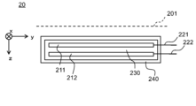
- FIG. FIG. 2 is a cross-sectional view illustrating the structure of a secondary battery.
- FIG. 2 is a schematic diagram illustrating how a secondary battery is measured with a measuring device. It is a figure which shows the modification of a sensor part.
- FIG. 3 is a diagram for explaining the voltage applied to the secondary battery by the measuring device.
- FIG. 3 is a diagram for explaining the voltage applied to the secondary battery by the measuring device.
- FIG. 2 is a diagram illustrating a computer for realizing a measuring device. It is a figure which illustrates the structure of the switching part and voltage application part with which the measuring device based on 2nd Embodiment is equipped.
- FIG. 7 is a diagram for explaining the operation of the measuring device according to the second embodiment.
- (a) to (g) are diagrams showing examples in which the frequency of a periodic signal output from a multiplier is changed.
- FIG. 7 is a diagram illustrating a signal flow in a measurement unit according to a third embodiment.
- FIG. 7 is a diagram illustrating a hardware configuration of a measuring section according to a third embodiment.
- FIG. 7 is a diagram illustrating the configuration of a measuring device according to a third embodiment.
- FIG. 2 is a schematic cross-sectional view showing the structure of a secondary battery that is a measurement target.
- FIG. 2 is a diagram showing measurement areas and defect positions in a photograph of a secondary battery.
- FIG. 6 is a diagram showing a map generated using the measurement results of the transient response of the magnetic field.
- FIG. 1 is a diagram illustrating the functional configuration of a measuring device 10 according to the first embodiment.
- the measuring device 10 is a device that measures a secondary battery 20.
- the measuring device 10 includes a voltage applying section 140, a switching section 120, a measuring section 160, and a processing section 180.
- the voltage application unit 140 applies a predetermined voltage to the secondary battery 20 that is determined based on the open circuit voltage (OCV) of the secondary battery 20 .
- the switching unit 120 switches between a first state in which a predetermined voltage is applied to the secondary battery 20 and a second state in which the secondary battery is opened.
- the measurement unit 160 measures the transient response of the magnetic field outside the secondary battery 20 when switching from the first state to the second state.
- the processing unit 180 generates information regarding the inside of the secondary battery 20 using the measurement results by the measurement unit 160. This will be explained in detail below.
- the measuring device 10 further includes a control section 190.
- the control section 190 controls the switching section 120, the voltage application section 140, and the measurement section 160.
- the secondary battery 20 may include a plurality of positive electrodes 211 and a plurality of negative electrodes 212.
- An electrolyte 230 is located between the positive electrode 211 and the negative electrode 212.
- the electrolyte 230 may be liquid, solid, or gel. Further, a separator may be further provided between the positive electrode 211 and the negative electrode 212.
- the positive electrode 211, the negative electrode 212, and the electrolyte 230 are covered and sealed with a package 240.
- Package 240 is, for example, a metal package.
- One end of the positive electrode terminal 221 is electrically connected to the positive electrode 211 inside the package 240, and the other end of the positive electrode terminal 221 is located outside the package 240.
- the positive electrode terminal 221 is electrically connected to the plurality of positive electrodes 211.
- One end of the negative electrode terminal 222 is electrically connected to the negative electrode 212 inside the package 240, and the other end of the negative electrode terminal 222 is located outside the package 240.
- the negative electrode terminal 222 is electrically connected to the plurality of negative electrodes 212.
- the stacking direction of the positive electrode terminal 221 and the negative electrode 212 will be referred to as the z direction, and two directions that are perpendicular to the z direction and mutually orthogonal will be referred to as the x direction and the y direction.
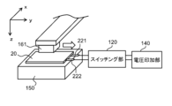
- FIG. 3 is a schematic diagram illustrating how the measuring device 10 measures the secondary battery 20.
- the measuring device 10 At the time of measurement by the measuring device 10, at least one of the positive terminal 221 and the negative terminal 222 of the secondary battery 20 is connected to the voltage application section 140 via the switching section 120. By doing so, a configuration is created in which voltage can be applied between the positive electrode terminal 221 and the negative electrode terminal 222, that is, to the secondary battery 20.
- One of the positive terminal 221 and the negative terminal 222 may be grounded.
- FIG. 4 is a diagram showing a modification of the sensor section 161.
- the measuring section 160 includes a plurality of sensor elements 165 arranged in a matrix in a sensor section 161.
- the sensor element 165 may be any magnetic sensor, such as a coil, a Hall element, an optically pumped magnetic sensor, a diamond magnetic sensor, a magnetoresistive sensor, or a magnetoresistive element.
- the plurality of sensor elements 165 are integrated. According to this modification, instead of measuring at a plurality of positions by scanning with the sensor unit 161 as shown in FIG. 3, measurement at a plurality of positions can be performed simultaneously using a plurality of sensor elements 165. Therefore, measurement time can be significantly shortened.
- the plurality of sensor elements 165 are two-dimensionally arranged in a matrix. Therefore, data of measurement points arranged two-dimensionally within the plane 201 is obtained.
- the plurality of sensor elements 165 may be arranged one-dimensionally in a line. In that case, the measurement may be performed by moving the plurality of sensor elements 165 in a direction perpendicular to the direction in which the plurality of sensor elements 165 are lined up. With this method as well, data at measurement points (measurement positions) arranged two-dimensionally within the plane 201 can be obtained.
- the direction of the magnetic field measured by the measurement unit 160 may be one direction, two directions, or three directions.
- the measurement unit 160 measures components of the magnetic field in one or more of the x direction, y direction, and z direction.
- the measurement unit 160 measures at least one of the x-direction component and the y-direction component of the magnetic field vector.
- the sensor unit 161 includes a coil
- the measuring unit 160 can measure the axial component of the coil, and can measure the components of the magnetic field in multiple directions by changing the direction of the coil or using multiple coils. Can be measured.
- the voltage application section 140 includes at least a DC voltage source.
- the switching section 120 switches whether or not to apply the output voltage of the voltage application section 140 to the secondary battery 20 .
- Switching section 120 is, for example, a switch or a transistor.
- the voltage application section 140 outputs a predetermined voltage V1 .
- the predetermined voltage V1 is a voltage determined based on the open circuit voltage. For example, ⁇ V 1 , which is the difference between the open circuit voltage and the output voltage of the voltage applying unit 140, is determined in advance, and by adding ⁇ V 1 to the measured open circuit voltage of the secondary battery 20, the secondary battery 20 The voltage V 1 for is determined.
- the open circuit voltage of the secondary battery 20 can be confirmed by separate measurement prior to measurement.
- the switching unit 120 is in the ON state
- the output voltage of the voltage application unit 140 is applied to the secondary battery 20. That is, the first state is when the switching section 120 is in the ON state.
- the secondary battery 20 is charged in the first state.
- the switching section 120 when the switching section 120 is in the OFF state, the output voltage of the voltage application section 140 is not applied to the secondary battery 20.
- the positive terminal 221 and negative terminal 222 of the secondary battery 20 are in an open state (floating state). That is, the second state is when the switching section 120 is in the OFF state. In the second state, no charge occurs in or out of the positive terminal 221 and the negative terminal 222.
- the voltage application section 140 outputs a predetermined voltage V2 .
- the predetermined voltage V2 is a voltage determined based on the open circuit voltage. For example, ⁇ V 2 , which is the difference between the open-circuit voltage and the output voltage of the voltage applying unit 140, is determined in advance, and by subtracting ⁇ V 2 from the measured open-circuit voltage of the secondary battery 20, the voltage applied to the secondary battery 20 is determined in advance. V2 is determined.
- the switching unit 120 is in the ON state
- the output voltage of the voltage application unit 140 is applied to the secondary battery 20. That is, the first state is when the switching section 120 is in the ON state. In the example shown in the figure, the secondary battery 20 is discharged in the first state.
- a magnetic field is generated by the movement of charges during this relaxation process, and the magnetic field leaks to the outside of the secondary battery 20 as well.
- the measurement unit 160 measures this leaked magnetic field.
- how the charge distribution is relaxed depends on the distribution of electrical characteristics (impedance, etc.) inside the secondary battery 20. Therefore, it can be said that the magnetic field measured by the measurement unit 160 includes information on the distribution of electrical characteristics inside the secondary battery 20.
- the secondary battery 20 is neither charged nor discharged in the second state. That is, the measurement is performed with the current flowing through the positive terminal 221 and the negative terminal 222 cut off. The effect of this will be further explained. If a magnetic field is measured while a current is flowing through the electrodes of the secondary battery 20, current concentration will occur near the positive terminal 221 and negative terminal 222, and a strong magnetic field will occur near these terminals. Measurements are taken. In order to measure such a strong magnetic field, it is necessary to increase the measurement range of the magnetic field by the sensor. On the other hand, in a large measurement range, it becomes difficult to measure in detail a weak magnetic field at a position away from the positive terminal 221 and the negative terminal 222.
- the processing unit 180 calculates the feature amount of the transient response by processing the transient response measured by the measurement unit 160. For example, the processing unit 180 calculates the time average of the magnetic field measured by the measurement unit 160 as a feature quantity. Alternatively, the processing unit 180 may calculate the time constant of the transient response measured by the measurement unit 160 as the feature amount. The feature amount is not limited to these values, and various statistical values can be used as the feature amount. As described above, when the measurement unit 160 measures transient responses at a plurality of positions within one or more planes 201 outside the secondary battery 20, the processing unit 180 generates a map indicating information inside the secondary battery 20. can be generated. The processing unit 180 generates a map showing the distribution of the calculated feature amounts. The map generated by the processing unit 180 can be output as an image. According to such an image, a contrast occurs between the defective part and the normal part inside the secondary battery 20. Therefore, the user who has checked the image can understand the presence or absence and location of a defective part.
- the processing unit 180 may determine whether or not there is an abnormality in the secondary battery 20 using the measurement result by the measurement unit 160.
- the processing unit 180 may output a notification when it is determined that there is an abnormality in the secondary battery 20.
- the processing unit 180 determines that there is no abnormality in the secondary battery 20. If the feature amount is not within the normal range, the processing unit 180 determines that there is an abnormality in the secondary battery 20.
- the normal range can be determined through prior testing, etc.
- the processing unit 180 can read out information indicating the normal range, which is stored in a storage unit accessible from the processing unit 180, and use it for determination.
- the information indicating the normal range may be one or more threshold values indicating the edges of the normal range.
- the balance between the amount of charge and the amount of discharge is maintained by repeating the first state a plurality of times.
- the amount of charge is quantified by the product t c ⁇ V 1 of the length of time t c in the first state shown in FIG. 5 and the difference ⁇ V 1 between V 1 and the open circuit voltage.
- the lengths of the plurality of first states may be the same or different. Moreover, the difference between the voltage applied to the secondary battery 20 and the open-circuit voltage in the first state multiple times may be the same or different.
- t c and t d are each, for example, 0.1 seconds or more and 10 seconds or less.
- ⁇ V 1 and ⁇ V 2 are each, for example, 0.01 V or more and 4 V or less.
- ⁇ V 1 and ⁇ V 2 may be the same or different.
- one of ⁇ V 1 and ⁇ V 2 may be a value obtained by adding a compensation value to the other of ⁇ V 1 and ⁇ V 2 to compensate for the asymmetry between the positive electrode and the negative electrode of the secondary battery 20.
- the measurement unit 160 indicates a transient response when the secondary battery 20 is switched from the first state where it is charged to a second state (hereinafter referred to as a post-charge transient response), and a transient response when the secondary battery 20 is switched from the first state where it is discharged to the second state.
- a transient response when switching between the two states (hereinafter referred to as post-discharge transient response) may be measured, or only one of them may be measured.
- a feature amount can be calculated for each of the post-charging transient response data and the post-discharging transient response data.
- the strength of the magnetic field that is, the absolute value
- the switching section 120, the voltage application section 140, the processing section 180, and the control section 190 of the measuring device 10 are configured using hardware (e.g., an electronic circuit) that realizes the switching section 120, the voltage application section 140, the processing section 180, and the control section 190. ), or may be realized using a combination of hardware and software (eg, a combination of an electronic circuit and a program that controls it).
- hardware e.g., an electronic circuit
- a combination of hardware and software e.g, a combination of an electronic circuit and a program that controls it.
- FIG. 7 is a diagram illustrating a computer 1000 for realizing the measuring device 10.
- Computer 1000 is any computer.
- the computer 1000 is an SoC (System On Chip), a Personal Computer (PC), a server machine, a tablet terminal, a smartphone, or the like.
- the computer 1000 may be a dedicated computer designed to implement the measuring device 10, or may be a general-purpose computer.
- the measuring device 10 may be realized using one computer 1000 or may be realized using a combination of multiple computers 1000.
- the input/output interface 1100 is an interface for connecting the computer 1000 and an input/output device.
- an input device such as a keyboard and an output device such as a display are connected to the input/output interface 1100.
- the method by which the input/output interface 1100 connects to the input device and the output device may be a wireless connection or a wired connection.
- the network interface 1120 is an interface for connecting the computer 1000 to a network.
- This communication network is, for example, a LAN (Local Area Network) or a WAN (Wide Area Network).
- the method by which the network interface 1120 connects to the network may be a wireless connection or a wired connection.
- the storage device 1080 stores program modules for realizing each functional component of the measuring device 10.
- Processor 1040 reads each of these program modules into memory 1060 and executes them, thereby realizing the functions corresponding to each program module.
- the measuring method according to the present embodiment is realized by the measuring device 10 according to the present embodiment.
- the Measurements can be performed stably, and information about the inside of the secondary battery can be obtained. Moreover, magnetic field measurement can be performed over the entire secondary battery 20 in a good measurement range, and even weak magnetic fields can be measured with high accuracy.
- FIG. 8 is a diagram illustrating the configuration of the switching section 120 and the voltage application section 140 included in the measuring device 10 according to the second embodiment.
- FIG. 9 is a diagram for explaining the operation of the measuring device 10 according to this embodiment.
- the measuring device 10 and measuring method according to this embodiment are the same as the measuring device 10 and measuring method according to the first embodiment, respectively, except for the points described below.
- the voltage applying unit 140 applies a predetermined voltage to the secondary battery 20 using a periodic signal. Then, the switching unit 120 switches between the first state and the second state using a periodic signal having a frequency that is an integral multiple of the frequency of this periodic signal. This will be explained in detail below.
- the voltage application section 140 includes a DC voltage source 141 and an oscillator 142.
- the DC voltage source 141 is set to output a DC voltage having the same voltage value as the open-circuit voltage of the secondary battery 20.
- the open-circuit voltage of the secondary battery 20 can be measured separately prior to measurement with the measuring device 10. Then, prior to measurement with the measuring device 10, the user of the measuring device 10 sets the output voltage value of the DC voltage source 141.
- the oscillator 142 outputs, for example, a rectangular wave voltage signal.
- the signal output by the oscillator 142 will also be referred to as a reference signal below.
- the DC voltage source 141 and the oscillator 142 are connected in series, and the voltage application section 140 outputs a voltage VA in which the output voltage of the DC voltage source 141 and the output voltage of the oscillator 142 are superimposed.
- the output voltage V A of the voltage application section 140 is applied between the positive terminal 221 and the negative terminal 222 of the secondary battery 20, so that the voltage of the secondary battery 20 is A predetermined voltage determined based on the open circuit voltage will be applied.
- the upper part of FIG. 9 shows the waveform of the output voltage VA of the voltage application section 140.
- the waveform of voltage VA is a rectangular wave centered around the open circuit voltage.
- the waveform of the voltage VA is the reference waveform plus a DC offset corresponding to the open circuit voltage.
- the frequency of the reference signal can be arbitrarily set depending on the characteristics of the secondary battery 20, and is, for example, 0.1 Hz or more and 100 kHz or less. Further, the amplitude of the reference signal is, for example, 0.02 V pp or more and 8 V pp or less.
- Voltage V 1 and voltage V 2 which are the peak values of voltage VA, respectively become voltages applied to secondary battery 20 in the first state.
- the secondary battery 20 is charged when a voltage V1 higher than the open circuit voltage is applied.
- the secondary battery 20 is discharged when a voltage V2 lower than the open circuit voltage is applied.
- the switching section 120 includes a MOSFET 121, a multiplier 122, and an AND gate 123.
- the output signal of the AND gate 123 is input to the gate of the MOSFET 121.
- One of the source and drain of the MOSFET 121 is connected to one output terminal of the voltage application section 140.
- the other of the source and drain of MOSFET 121 is connected to one of positive terminal 221 and negative terminal 222 of secondary battery 20 .
- the other output terminal of the voltage application section 140 is connected to the other of the positive terminal 221 and the negative terminal 222 of the secondary battery 20.
- the output terminal of the voltage application section 140 means a terminal that outputs the voltage VA .
- the MOSFET 121 is a p-channel MOSFET, but the MOSFET 121 is not limited to this example, and may be an n-channel MOSFET or another switch element.
- a control signal from the control section 190 and an output signal from the multiplier 122 are input to two input terminals of the AND gate 123 .
- the control unit 190 continues to input a "1" level signal as a control signal to the AND gate 123 while in the first state or the second state (for example, during a measurement process described later in the third embodiment).
- the control unit 190 sends a "0" level signal to the AND gate 123 as a control signal while the state is in a state other than the first state or the second state (for example, during a specific process described later in the third embodiment).
- Keep typing In this example, it is assumed that a "1" level signal is a negative voltage, and a "0" level signal is 0V.
- the reference signal output from the oscillator 142 is input to the multiplier 122 .
- This reference signal is a periodic signal having the same frequency as the reference signal.
- Multiplier 122 outputs a periodic signal (for example, a rectangular wave) having a frequency that is an integral multiple of the frequency of the reference signal.
- FIG. 9 shows an example in which the multiplier 122 outputs a periodic signal having a frequency twice that of the reference signal. Further, this figure shows an example in which the control unit 190 continues to input a "1" level signal to the AND gate 123 as a control signal. That is, when the output of the multiplier 122 is at the "1" level, the output of the AND gate 123 is at the "1" level, and at other times, the output of the AND gate 123 is at the "0" level. As a result, the output of the AND gate 123 becomes a signal that switches between the "1" level and the "0" level at a frequency twice the frequency of the reference signal, that is, twice the frequency of the reference signal.
- the MOSFET 121 is in the ON state when the input to the gate is at the "1" level, and is in the OFF state when the input to the gate is at the "0" level. Note that in the example of this figure, when the input to the gate of MOSFET 121 is at the "1" level, the gate potential is negative.
- the application of voltage VA to the secondary battery 20 is turned ON/OFF at a frequency twice the frequency of the reference signal.
- the period in which the MOSFET 121 is in the ON state corresponds to the period in the first state
- the period in which the MOSFET 121 is in the OFF state corresponds to the period in the second state.
- the first state and the second state are repeated at a frequency twice the frequency of the reference signal.
- an example of a waveform assumed as the magnetic flux density outside the secondary battery 20 is shown.
- the measurement unit 160 according to the present embodiment can repeatedly measure the transient response of the secondary battery 20 in substantially the same power storage state.
- the processing unit 180 can obtain information with a high S/N ratio using the plurality of measured transient responses. Consequently, abnormal locations in the secondary battery 20 can be detected with high accuracy.
- the hardware configurations of the switching section 120 and the voltage application section 140 included in the measuring device 10 according to this embodiment are not limited to the example shown in FIG. 8 .
- FIGS. 10(a) to 10(g) are diagrams showing examples in which the frequency of the periodic signal output by the multiplier 122 is changed.
- FIG. 10(a) shows the waveform of the reference signal.
- 10(b) and 10(c) show the voltage VB and the assumed output waveform of the measurement unit 160 when the multiplier 122 outputs a periodic signal having twice the frequency of the reference signal. An example is shown for each.
- FIG. 10(d) and FIG. 10(e) show the voltage VB and the assumed output waveform of the measurement unit 160 when the multiplier 122 outputs a periodic signal having a frequency four times the frequency of the reference signal. An example is shown for each.
- 10(f) and 10(g) show the voltage VB and the assumed output waveform of the measurement unit 160 when the multiplier 122 outputs a periodic signal having a frequency six times the frequency of the reference signal. An example is shown for each. Note that the secondary battery 20 is in an open state in the broken line portions of FIGS. 10(b), 10(d), and 10(f). V 0 in FIGS. 10(c), 10(e), and 10(g) is the sensor output value when the magnetic flux density is zero.
- the multiplier 122 outputting a periodic signal having a frequency that is an even multiple of the frequency of the reference signal, the set of the first state and the second state in which the secondary battery 20 is charged continues N times. Then, the set of the first state and the second state in which the secondary battery 20 is discharged continues N times. In other words, the number of times the secondary battery 20 is in the first state where it is charged is equal to the number of times the secondary battery 20 is in the first state where it is discharged. Therefore, the transient response can be repeatedly measured while maintaining the balance between the amount of charge and the amount of discharge.
- N is an integer of 1 or more.
- FIG. 11 is a diagram illustrating a signal flow in the measurement unit 160 according to the third embodiment.
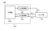
- FIG. 12 is a diagram illustrating the hardware configuration of the measuring section 160 according to this embodiment.
- the measuring device 10 according to this embodiment is the same as the measuring device 10 according to the first or second embodiment except for the points described below.
- the measuring method according to this embodiment is the same as the measuring method according to the first or second embodiment except for the points described below.
- the measuring device 10 includes a control section 190 that controls the voltage application section 140 and the measurement section 160.
- the measurement section 160 includes a sensor section 161 and a sensor drive section 162.
- the control unit 190 controls the voltage application unit 140 and the measurement unit 160 so that the identification process and the measurement process are performed in order.
- identifying step a fixed input value to the sensor unit 161 for canceling at least a portion of the noise magnetic field is identified.
- a transient response is measured while a fixed input value is input to the sensor section 161.
- the sensor drive unit 162 controls the sensor unit 161 so that the output of the sensor unit 161 approaches the reference level while a voltage corresponding to the open circuit voltage is applied to the secondary battery 20.
- the control unit 190 controls the voltage application unit 140 and the measurement unit 160 so that the fixed input value is specified by feedback-controlling the input value.
- the secondary battery 20 may contain, for example, a ferromagnetic material as an electrode material.
- a ferromagnetic material contained in the secondary battery 20 include nickel, cobalt, iron, and the like. Due to this ferromagnetic material, a magnetic field can be generated from the secondary battery 20 regardless of charge relaxation. Such magnetic fields act as noise in measurements. In addition, there may also be a noise magnetic field due to the earth's magnetism or a magnetic body near the measurement location.
- the sensor section 161 can include any magnetic sensor such as a coil, a Hall element, an optically pumped magnetic sensor, a diamond magnetic sensor, a magnetic impedance sensor, or a magnetoresistive element.
- the sensor section 161 has, for example, a core and one or more coils wound around the core.
- an input signal SFB which is a feedback signal, can be input to the sensor section 161.
- a current according to the input signal SFB flows through the coil 166 of the sensor section 161, and a magnetic field is generated.
- the generated magnetic field can cancel out the noise magnetic field.
- the sensor unit 161 outputs a monitor signal Sm indicating the level of the input signal SFB . Further, the sensor unit 161 outputs an output signal S out indicating the measured magnetic flux density.
- the sensor drive section 162 subtracts a predetermined target value from the output signal S out from the sensor section 161, and adds a monitor signal S m to the obtained signal.
- the sensor drive unit 162 may further amplify the signal after the addition.
- the target value corresponds to the signal value of the output signal S out of the sensor unit 161 when the measured magnetic flux density is zero.
- Such a target value is set as a reference level.
- Such a sensor driving section 162 enables feedback control to cancel the noise magnetic field measured by the sensor section 161.
- the sensor drive section 162 includes a D/A converter 164 and an A/D converter 163.
- the sensor drive section 162 is realized using the computer 1000.
- the output signal S out and the monitor signal S m output from the sensor section 161 are input to the computer 1000 via the A/D converter 163 .
- the input signal S FB is output from the computer 1000 and input to the sensor section 161 via the D/A converter 164 .
- the hardware configuration of the computer 1000 for realizing the sensor drive unit 162 is represented, for example, in FIG. 7, similarly to the control unit 190 and the like.
- the storage device 1080 of the computer 1000 for realizing the sensor drive section 162 further stores a program module for realizing the functions of the sensor drive section 162.
- FIG. 13 is a diagram illustrating the configuration of the measuring device 10 according to this embodiment. This figure shows an example in which the switching section 120 and the voltage application section 140 have the same configurations as the switching section 120 and the voltage application section 140, respectively, of the measuring device 10 according to the second embodiment.
- the configuration of section 140 is not limited to this example.
- the measuring device 10 sequentially performs the identification process and the measurement process. Specifically, at each measurement position, one identification step is performed prior to the measurement step.
- Voltage application section 140 includes, for example, a switch 143 that can be switched under the control of control section 190. By switching this switch 143, a state in which a voltage corresponding to the open circuit voltage is applied to the secondary battery 20 from the DC voltage source 141, and a state for the measurement process that realizes the first state and the second state. can be switched.
- the control unit 190 can control switching of the switch 143.
- feedback control by the sensor drive unit 162 is started while a voltage corresponding to the open circuit voltage is applied to the secondary battery 20 from the DC voltage source 141.
- a voltage corresponding to the open-circuit voltage is applied to the secondary battery 20
- the secondary battery 20 is neither charged nor discharged, and therefore only the noise magnetic field is measured.
- the control loop is repeated at a predetermined cycle until the output signal S out of the sensor section 161 reaches around the reference level, which is the cancellation point of the noise magnetic field.
- the sensor drive unit 162 ends the feedback control when the output signal S out falls within a predetermined range near the reference level.
- the sensor drive unit 162 sets the input signal (feedback signal) SFB at the end of this feedback control to a fixed input value.
- this fixed input value can be said to be a set value that can appropriately cancel out the noise magnetic field at the measurement position.
- the sensor drive section 162 fixes the input signal SFB to the sensor section 161 at a fixed input value.
- the control unit 190 controls the sensor drive unit 162 so that such operations are performed in the specific process and the measurement process.
- the first state and the second state are realized, and the transient response of the magnetic field in the second state is measured by the measurement unit 160.
- the switching unit 120 is controlled by a control signal from a computer 1000 having the function of a control unit 190.
- the control unit 190 inputs a "0" level control signal to the AND gate 123 during the specific process. Further, during the measurement process, a control signal of "1" level is input to the AND gate 123. Further, the control unit 190 monitors the state of switching by the switching unit 120 by monitoring the output signal of the AND gate 123. Then, the control unit 190 identifies the period of the second state based on the monitored switching state, and acquires the output signal S out of the sensor unit 161 during the period of the second state.
- the measuring device 10 according to the fourth embodiment is the same as the measuring device 10 according to at least one of the first to third embodiments except for the points described below.
- the measuring method according to this embodiment is the same as the measuring method according to at least one of the first to third embodiments except for the points described below.
- the measuring unit 160 of the measuring device 10 measures magnetic field components in two directions perpendicular to each other as a transient response. Then, the processing unit 180 generates the conductivity distribution inside the secondary battery 20 using the magnetic field components in two directions. This will be explained in detail below.
- the measurement unit 160 measures the magnetic field component in the x direction and the magnetic field component in the y direction at a plurality of measurement points (x, y) within the plane 201 parallel to the main surfaces of the positive electrode 211 and the negative electrode 212.
- the x-direction magnetic field component means the x-direction component of magnetic flux density
- the y-direction magnetic field component means the y-direction component of magnetic flux density.
- the processing unit 180 calculates, for example, the time average of each transient response of the magnetic field components in each direction. Then, the average value of the time average is calculated as a feature quantity for each measurement position. By doing this, for each measurement point (x, y), the feature quantity of the magnetic field component in the x direction (hereinafter referred to as the x component) and the feature quantity of the magnetic field component in the y direction (hereinafter referred to as the y component) are calculated. can get.
- the processing unit 180 further generates the conductivity distribution inside the secondary battery 20 using these feature amounts.
- a method for generating the conductivity distribution inside the secondary battery 20 for example, the method described in Patent Document 1 can be used.
- the processing unit 180 derives a conductivity distribution on a predetermined plane within the secondary battery 20 that satisfies a plurality of relational expressions for the obtained x and y components.
- the predetermined plane is a plane parallel to the xy plane.
- the processing unit 180 derives the conductivity distribution represented by ⁇ based on the following equations (1) to (3).
- the coordinate in the x direction is expressed by x
- the coordinate in the y direction is expressed by y
- the coordinate in the z direction is expressed by z
- the first electrode closest to the plane 201 The coordinate in the z direction of the positive electrode 211 or the negative electrode 212) is expressed as z0
- the x component is expressed as Hx
- the y component is expressed as Hy
- the thickness of the first electrode in the z direction is expressed as h.
- the distance between a pair of electrodes including the first electrode is expressed by h T
- the conductivity of the first electrode is expressed by ⁇ 0
- the potential distribution is The delta function is expressed as ⁇
- the differential of the delta function is expressed as ⁇ '
- the partial differential with respect to x is expressed as ⁇ x
- the partial differential with respect to y is expressed as ⁇ y .
- processing unit 180 can derive the conductivity distribution using various formulas derived from equations (1) to (3).
- the processing unit 180 can output the derived conductivity distribution, for example, as an image.
- the processing unit 180 can output the generated image as output information, for example, by displaying it on a display provided in the processing unit 180.
- the processing unit 180 may output the output information to a device external to the measuring device 10, or may retain the output information in a storage device that is accessible from the processing unit 180.
- the same functions and effects as in the first embodiment can be obtained.
- the conductivity distribution within the secondary battery 20 can be grasped.
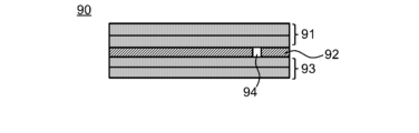
- FIG. 14 is a schematic cross-sectional view showing the structure of the secondary battery 90 that was the object of measurement.
- the secondary battery 90 was measured using the method described in the third embodiment.
- Secondary battery 90 included a laminate of a negative electrode 91, a separator 92, and a positive electrode 93, and the laminate was covered with a package. Note that the package is omitted in this figure.
- a secondary battery 90 to be measured was a separator 92 in which a hole was made as a defect 94 as shown in the figure. By making a hole in the separator 92, the positive electrode 93 and the negative electrode 91 were brought into physical contact at the defect 94, resulting in a short circuit.
- FIG. 15 is a diagram showing the measurement area 95 and the position of the defect 94 in a photograph of the secondary battery 90.
- the measurement area was 120 mm x 100 mm, and a 16 x 12 pixel map was obtained.
- the cumulative time at each measurement position was 200 seconds.
- the frequency of the reference signal was 4 Hz, and the current flowing through the secondary battery 90 during charging and discharging in the measurement process was 500 mA pp . Note that the amount of voltage drop due to natural discharge of the secondary battery 90 was 1.5 mV/day (from a fully charged state of 3.67 V).
- FIG. 16 is a diagram showing a map generated using the measurement results of the transient response of the magnetic field. To generate this map, the absolute value of the time-averaged magnetic flux density of the measured transient response was calculated for each measurement location. Then, the average value (referred to as average magnetic flux density in FIG. 16 and hereinafter) of the absolute values calculated for multiple transient responses was calculated. The distribution of the calculated average magnetic flux density is shown on the map. In the generation of this map, the average value was calculated using data on the post-charge transient response and data on the post-discharge transient response without distinguishing them. In this figure, the map is shown superimposed on a photograph of the secondary battery 90 with corresponding positions.
- the average magnetic flux density was measured near the defect 94 at a level different from that in other areas. Specifically, the average magnetic flux density was higher in the vicinity of the defect 94 than in other regions. From this result, it was confirmed that information inside the secondary battery 90 can be obtained by this measurement method and defects can be detected.
- Measuring device 20 Secondary battery 120 Switching section 121 MOSFET 122 Multiplier 123 AND gate 140 Voltage application section 141 DC voltage source 142 Oscillator 143 Switch 150 Stage 160 Measurement section 161 Sensor section 162 Sensor drive section 180 Processing section 190 Control section 211 Positive electrode 212 Negative electrode 221 Positive terminal 222 Negative terminal 230 Electrolyte 240 Package 1000 calculator
Landscapes
- Physics & Mathematics (AREA)
- General Physics & Mathematics (AREA)
- Condensed Matter Physics & Semiconductors (AREA)
- Chemical & Material Sciences (AREA)
- Chemical Kinetics & Catalysis (AREA)
- Electrochemistry (AREA)
- Engineering & Computer Science (AREA)
- General Chemical & Material Sciences (AREA)
- Manufacturing & Machinery (AREA)
- Analytical Chemistry (AREA)
- General Health & Medical Sciences (AREA)
- Immunology (AREA)
- Pathology (AREA)
- Biochemistry (AREA)
- Life Sciences & Earth Sciences (AREA)
- Health & Medical Sciences (AREA)
- Secondary Cells (AREA)
- Measurement Of Current Or Voltage (AREA)
Priority Applications (5)
| Application Number | Priority Date | Filing Date | Title |
|---|---|---|---|
| KR1020247019586A KR102871071B1 (ko) | 2022-07-07 | 2023-06-29 | 측정 장치 및 측정 방법 |
| CN202380018142.8A CN118591734A (zh) | 2022-07-07 | 2023-06-29 | 测定装置及测定方法 |
| JP2024532087A JP7616735B2 (ja) | 2022-07-07 | 2023-06-29 | 測定装置および測定方法 |
| EP23835426.0A EP4553521A1 (en) | 2022-07-07 | 2023-06-29 | Measurement device and measurement method |
| US18/880,335 US20260009871A1 (en) | 2022-07-07 | 2023-06-29 | Measurement apparatus and measurement method |
Applications Claiming Priority (2)
| Application Number | Priority Date | Filing Date | Title |
|---|---|---|---|
| JP2022-109689 | 2022-07-07 | ||
| JP2022109689 | 2022-07-07 |
Publications (1)
| Publication Number | Publication Date |
|---|---|
| WO2024009894A1 true WO2024009894A1 (ja) | 2024-01-11 |
Family
ID=89453468
Family Applications (1)
| Application Number | Title | Priority Date | Filing Date |
|---|---|---|---|
| PCT/JP2023/024264 Ceased WO2024009894A1 (ja) | 2022-07-07 | 2023-06-29 | 測定装置および測定方法 |
Country Status (7)
| Country | Link |
|---|---|
| US (1) | US20260009871A1 (https=) |
| EP (1) | EP4553521A1 (https=) |
| JP (1) | JP7616735B2 (https=) |
| KR (1) | KR102871071B1 (https=) |
| CN (1) | CN118591734A (https=) |
| TW (1) | TW202409515A (https=) |
| WO (1) | WO2024009894A1 (https=) |
Cited By (1)
| Publication number | Priority date | Publication date | Assignee | Title |
|---|---|---|---|---|
| WO2025004516A1 (ja) * | 2023-06-26 | 2025-01-02 | 株式会社 Integral Geometry Science | 蓄電池検査装置及び蓄電池検査方法 |
Citations (8)
| Publication number | Priority date | Publication date | Assignee | Title |
|---|---|---|---|---|
| JP2012242153A (ja) * | 2011-05-17 | 2012-12-10 | Pulstec Industrial Co Ltd | 2次電池の検査装置及び検査方法 |
| JP2014089819A (ja) * | 2012-10-29 | 2014-05-15 | Hitachi Maxell Ltd | 磁場計測装置およびそれを用いた電池劣化検査方法 |
| WO2015136930A1 (ja) | 2014-03-13 | 2015-09-17 | 国立大学法人神戸大学 | 電池検査装置および電池検査方法 |
| WO2015136931A1 (ja) * | 2014-03-12 | 2015-09-17 | 国立大学法人神戸大学 | 導電率分布導出方法および導電率分布導出装置 |
| JP2016197054A (ja) * | 2015-04-03 | 2016-11-24 | 国立大学法人 東京大学 | 二次電池の検査方法 |
| WO2017187791A1 (ja) * | 2016-04-28 | 2017-11-02 | 国立大学法人神戸大学 | 計測装置および計測方法 |
| WO2021024859A1 (ja) * | 2019-08-06 | 2021-02-11 | 株式会社 Integral Geometry Science | 蓄電池検査装置及び蓄電池検査方法 |
| JP2022109689A (ja) | 2021-01-15 | 2022-07-28 | Agc株式会社 | 断熱パネル及びその製造方法、並びに断熱容器 |
Family Cites Families (2)
| Publication number | Priority date | Publication date | Assignee | Title |
|---|---|---|---|---|
| JP7039963B2 (ja) * | 2017-11-28 | 2022-03-23 | 株式会社デンソー | 電池制御システム |
| KR102817147B1 (ko) * | 2018-09-05 | 2025-06-05 | 주식회사 엘지에너지솔루션 | 스위치 제어 장치 |
-
2023
- 2023-06-29 CN CN202380018142.8A patent/CN118591734A/zh active Pending
- 2023-06-29 JP JP2024532087A patent/JP7616735B2/ja active Active
- 2023-06-29 US US18/880,335 patent/US20260009871A1/en active Pending
- 2023-06-29 WO PCT/JP2023/024264 patent/WO2024009894A1/ja not_active Ceased
- 2023-06-29 EP EP23835426.0A patent/EP4553521A1/en active Pending
- 2023-06-29 KR KR1020247019586A patent/KR102871071B1/ko active Active
- 2023-07-05 TW TW112125034A patent/TW202409515A/zh unknown
Patent Citations (8)
| Publication number | Priority date | Publication date | Assignee | Title |
|---|---|---|---|---|
| JP2012242153A (ja) * | 2011-05-17 | 2012-12-10 | Pulstec Industrial Co Ltd | 2次電池の検査装置及び検査方法 |
| JP2014089819A (ja) * | 2012-10-29 | 2014-05-15 | Hitachi Maxell Ltd | 磁場計測装置およびそれを用いた電池劣化検査方法 |
| WO2015136931A1 (ja) * | 2014-03-12 | 2015-09-17 | 国立大学法人神戸大学 | 導電率分布導出方法および導電率分布導出装置 |
| WO2015136930A1 (ja) | 2014-03-13 | 2015-09-17 | 国立大学法人神戸大学 | 電池検査装置および電池検査方法 |
| JP2016197054A (ja) * | 2015-04-03 | 2016-11-24 | 国立大学法人 東京大学 | 二次電池の検査方法 |
| WO2017187791A1 (ja) * | 2016-04-28 | 2017-11-02 | 国立大学法人神戸大学 | 計測装置および計測方法 |
| WO2021024859A1 (ja) * | 2019-08-06 | 2021-02-11 | 株式会社 Integral Geometry Science | 蓄電池検査装置及び蓄電池検査方法 |
| JP2022109689A (ja) | 2021-01-15 | 2022-07-28 | Agc株式会社 | 断熱パネル及びその製造方法、並びに断熱容器 |
Cited By (1)
| Publication number | Priority date | Publication date | Assignee | Title |
|---|---|---|---|---|
| WO2025004516A1 (ja) * | 2023-06-26 | 2025-01-02 | 株式会社 Integral Geometry Science | 蓄電池検査装置及び蓄電池検査方法 |
Also Published As
| Publication number | Publication date |
|---|---|
| US20260009871A1 (en) | 2026-01-08 |
| CN118591734A (zh) | 2024-09-03 |
| KR20240110827A (ko) | 2024-07-16 |
| TW202409515A (zh) | 2024-03-01 |
| EP4553521A1 (en) | 2025-05-14 |
| KR102871071B1 (ko) | 2025-10-15 |
| JPWO2024009894A1 (https=) | 2024-01-11 |
| JP7616735B2 (ja) | 2025-01-17 |
Similar Documents
| Publication | Publication Date | Title |
|---|---|---|
| US11686699B2 (en) | System and method for anomaly detection and total capacity estimation of a battery | |
| Ilott et al. | Rechargeable lithium-ion cell state of charge and defect detection by in-situ inside-out magnetic resonance imaging | |
| Kindermann et al. | Long-term equalization effects in Li-ion batteries due to local state of charge inhomogeneities and their impact on impedance measurements | |
| US10566811B2 (en) | Method and apparatus estimating and controlling battery state | |
| WO2021044155A1 (en) | Battery characterisation and monitoring system | |
| EP4012819A1 (en) | Storage battery inspection device and storage battery inspection method | |
| US20170168119A1 (en) | Method for real time correction of ion concentration and coulomb counting state-of-charge (soc) in battery | |
| US20210123979A1 (en) | Estimating a Battery State from Electrical Impedance Measurements Using Convolutional Neural Network Means | |
| R-Smith et al. | Multiplexed 16× 16 Li-ion cell measurements including internal resistance for quality inspection and classification | |
| US10254352B2 (en) | Conductivity distribution derivation method and conductivity distribution derivation device | |
| JP7616735B2 (ja) | 測定装置および測定方法 | |
| JP2010160055A (ja) | 電池検査方法 | |
| JP2017223580A (ja) | 充放電装置 | |
| JP6461095B2 (ja) | 電池検査装置および電池検査方法 | |
| US11385294B2 (en) | Estimating a battery state from gradients of electrical impedance measurements | |
| JP2017150838A (ja) | 蓄電装置の測定方法および測定装置 | |
| US11474158B2 (en) | Analyzing electrical impedance measurements of an electromechanical battery | |
| JP2019158831A (ja) | 検査方法、検査装置及び学習モデル | |
| JP2023081521A (ja) | 漏電検出方法 | |
| WO2024097808A2 (en) | Electrochemical magnetic induction spectroscopy for electrochemical cells such as batteries | |
| Routh et al. | Particle filtering framework for health monitoring of lithium-ion batteries using ampere-hour throughput based semi-empirical model | |
| JP2017003325A (ja) | 二次電池の検査方法 | |
| JPH1164472A (ja) | バッテリー診断装置 | |
| JP7826019B2 (ja) | 検査装置、電池監視装置の検査方法 | |
| CN104049148B (zh) | 用于电池电阻测量系统的改进的精度的系统和方法 |
Legal Events
| Date | Code | Title | Description |
|---|---|---|---|
| 121 | Ep: the epo has been informed by wipo that ep was designated in this application |
Ref document number: 23835426 Country of ref document: EP Kind code of ref document: A1 |
|
| ENP | Entry into the national phase |
Ref document number: 2024532087 Country of ref document: JP Kind code of ref document: A |
|
| ENP | Entry into the national phase |
Ref document number: 20247019586 Country of ref document: KR Kind code of ref document: A |
|
| WWE | Wipo information: entry into national phase |
Ref document number: 1020247019586 Country of ref document: KR |
|
| WWE | Wipo information: entry into national phase |
Ref document number: 202380018142.8 Country of ref document: CN |
|
| WWE | Wipo information: entry into national phase |
Ref document number: 18880335 Country of ref document: US |
|
| WWE | Wipo information: entry into national phase |
Ref document number: 202517009896 Country of ref document: IN |
|
| WWE | Wipo information: entry into national phase |
Ref document number: 2023835426 Country of ref document: EP |
|
| NENP | Non-entry into the national phase |
Ref country code: DE |
|
| ENP | Entry into the national phase |
Ref document number: 2023835426 Country of ref document: EP Effective date: 20250207 |
|
| WWP | Wipo information: published in national office |
Ref document number: 202517009896 Country of ref document: IN |
|
| WWP | Wipo information: published in national office |
Ref document number: 2023835426 Country of ref document: EP |
|
| WWP | Wipo information: published in national office |
Ref document number: 18880335 Country of ref document: US |