WO2024009817A1 - 作業車両 - Google Patents
作業車両 Download PDFInfo
- Publication number
- WO2024009817A1 WO2024009817A1 PCT/JP2023/023484 JP2023023484W WO2024009817A1 WO 2024009817 A1 WO2024009817 A1 WO 2024009817A1 JP 2023023484 W JP2023023484 W JP 2023023484W WO 2024009817 A1 WO2024009817 A1 WO 2024009817A1
- Authority
- WO
- WIPO (PCT)
- Prior art keywords
- fuel
- work vehicle
- filling port
- fuel filling
- vehicle according
- Prior art date
Links
- 239000000446 fuel Substances 0.000 claims abstract description 306
- 239000002828 fuel tank Substances 0.000 claims abstract description 125
- 239000002826 coolant Substances 0.000 description 66
- 239000007789 gas Substances 0.000 description 58
- 230000005540 biological transmission Effects 0.000 description 41
- 238000010248 power generation Methods 0.000 description 31
- 239000002737 fuel gas Substances 0.000 description 27
- 238000001816 cooling Methods 0.000 description 26
- UFHFLCQGNIYNRP-UHFFFAOYSA-N Hydrogen Chemical compound [H][H] UFHFLCQGNIYNRP-UHFFFAOYSA-N 0.000 description 24
- 238000010586 diagram Methods 0.000 description 10
- 230000008878 coupling Effects 0.000 description 9
- 238000010168 coupling process Methods 0.000 description 9
- 238000005859 coupling reaction Methods 0.000 description 9
- XLYOFNOQVPJJNP-UHFFFAOYSA-N water Substances O XLYOFNOQVPJJNP-UHFFFAOYSA-N 0.000 description 9
- 238000006243 chemical reaction Methods 0.000 description 7
- 239000001257 hydrogen Substances 0.000 description 7
- 229910052739 hydrogen Inorganic materials 0.000 description 7
- 238000003860 storage Methods 0.000 description 7
- 238000002485 combustion reaction Methods 0.000 description 6
- 230000000694 effects Effects 0.000 description 6
- 239000007788 liquid Substances 0.000 description 5
- 230000007246 mechanism Effects 0.000 description 5
- 229910052751 metal Inorganic materials 0.000 description 5
- 239000002184 metal Substances 0.000 description 5
- 238000004891 communication Methods 0.000 description 4
- 238000001514 detection method Methods 0.000 description 4
- 238000003487 electrochemical reaction Methods 0.000 description 4
- 230000033001 locomotion Effects 0.000 description 4
- 239000000463 material Substances 0.000 description 4
- 241000209094 Oryza Species 0.000 description 3
- 235000007164 Oryza sativa Nutrition 0.000 description 3
- 238000013459 approach Methods 0.000 description 3
- 230000008901 benefit Effects 0.000 description 3
- 239000004918 carbon fiber reinforced polymer Substances 0.000 description 3
- 230000008859 change Effects 0.000 description 3
- 230000007423 decrease Effects 0.000 description 3
- 230000005611 electricity Effects 0.000 description 3
- 239000003792 electrolyte Substances 0.000 description 3
- 238000005516 engineering process Methods 0.000 description 3
- 239000011152 fibreglass Substances 0.000 description 3
- 150000002500 ions Chemical class 0.000 description 3
- 238000004519 manufacturing process Methods 0.000 description 3
- 239000012528 membrane Substances 0.000 description 3
- 235000009566 rice Nutrition 0.000 description 3
- 229920003002 synthetic resin Polymers 0.000 description 3
- 239000000057 synthetic resin Substances 0.000 description 3
- 230000000007 visual effect Effects 0.000 description 3
- 229920000049 Carbon (fiber) Polymers 0.000 description 2
- CURLTUGMZLYLDI-UHFFFAOYSA-N Carbon dioxide Chemical compound O=C=O CURLTUGMZLYLDI-UHFFFAOYSA-N 0.000 description 2
- 239000004917 carbon fiber Substances 0.000 description 2
- 239000002131 composite material Substances 0.000 description 2
- 238000010276 construction Methods 0.000 description 2
- 230000001276 controlling effect Effects 0.000 description 2
- 239000000110 cooling liquid Substances 0.000 description 2
- 238000013461 design Methods 0.000 description 2
- 239000000945 filler Substances 0.000 description 2
- 239000011521 glass Substances 0.000 description 2
- 230000000670 limiting effect Effects 0.000 description 2
- VNWKTOKETHGBQD-UHFFFAOYSA-N methane Chemical compound C VNWKTOKETHGBQD-UHFFFAOYSA-N 0.000 description 2
- 238000000034 method Methods 0.000 description 2
- 230000001590 oxidative effect Effects 0.000 description 2
- 230000009467 reduction Effects 0.000 description 2
- 230000002829 reductive effect Effects 0.000 description 2
- 230000001105 regulatory effect Effects 0.000 description 2
- 229920005989 resin Polymers 0.000 description 2
- 239000011347 resin Substances 0.000 description 2
- 239000002689 soil Substances 0.000 description 2
- 239000000126 substance Substances 0.000 description 2
- 230000001360 synchronised effect Effects 0.000 description 2
- 235000013311 vegetables Nutrition 0.000 description 2
- 238000003466 welding Methods 0.000 description 2
- HBBGRARXTFLTSG-UHFFFAOYSA-N Lithium ion Chemical compound [Li+] HBBGRARXTFLTSG-UHFFFAOYSA-N 0.000 description 1
- 241001124569 Lycaenidae Species 0.000 description 1
- 241000607479 Yersinia pestis Species 0.000 description 1
- 239000002253 acid Substances 0.000 description 1
- QVGXLLKOCUKJST-UHFFFAOYSA-N atomic oxygen Chemical compound [O] QVGXLLKOCUKJST-UHFFFAOYSA-N 0.000 description 1
- 229910000963 austenitic stainless steel Inorganic materials 0.000 description 1
- 230000000903 blocking effect Effects 0.000 description 1
- 229910002092 carbon dioxide Inorganic materials 0.000 description 1
- 239000001569 carbon dioxide Substances 0.000 description 1
- 238000007084 catalytic combustion reaction Methods 0.000 description 1
- 235000013339 cereals Nutrition 0.000 description 1
- 239000003638 chemical reducing agent Substances 0.000 description 1
- 230000003749 cleanliness Effects 0.000 description 1
- 238000013016 damping Methods 0.000 description 1
- 230000003247 decreasing effect Effects 0.000 description 1
- 238000009826 distribution Methods 0.000 description 1
- 230000005489 elastic deformation Effects 0.000 description 1
- 230000004720 fertilization Effects 0.000 description 1
- 239000003337 fertilizer Substances 0.000 description 1
- 239000012530 fluid Substances 0.000 description 1
- 238000003306 harvesting Methods 0.000 description 1
- 238000010438 heat treatment Methods 0.000 description 1
- 238000009413 insulation Methods 0.000 description 1
- 230000002452 interceptive effect Effects 0.000 description 1
- 239000003014 ion exchange membrane Substances 0.000 description 1
- 229910001416 lithium ion Inorganic materials 0.000 description 1
- 239000003550 marker Substances 0.000 description 1
- 230000000116 mitigating effect Effects 0.000 description 1
- 238000012986 modification Methods 0.000 description 1
- 230000004048 modification Effects 0.000 description 1
- 239000002420 orchard Substances 0.000 description 1
- 239000001301 oxygen Substances 0.000 description 1
- 229910052760 oxygen Inorganic materials 0.000 description 1
- 230000036961 partial effect Effects 0.000 description 1
- 230000002093 peripheral effect Effects 0.000 description 1
- 239000005518 polymer electrolyte Substances 0.000 description 1
- 238000012545 processing Methods 0.000 description 1
- 239000003507 refrigerant Substances 0.000 description 1
- 239000004576 sand Substances 0.000 description 1
- 239000004065 semiconductor Substances 0.000 description 1
- 238000004904 shortening Methods 0.000 description 1
- 239000007787 solid Substances 0.000 description 1
- 238000009331 sowing Methods 0.000 description 1
Images


Classifications
-
- B—PERFORMING OPERATIONS; TRANSPORTING
- B60—VEHICLES IN GENERAL
- B60K—ARRANGEMENT OR MOUNTING OF PROPULSION UNITS OR OF TRANSMISSIONS IN VEHICLES; ARRANGEMENT OR MOUNTING OF PLURAL DIVERSE PRIME-MOVERS IN VEHICLES; AUXILIARY DRIVES FOR VEHICLES; INSTRUMENTATION OR DASHBOARDS FOR VEHICLES; ARRANGEMENTS IN CONNECTION WITH COOLING, AIR INTAKE, GAS EXHAUST OR FUEL SUPPLY OF PROPULSION UNITS IN VEHICLES
- B60K15/00—Arrangement in connection with fuel supply of combustion engines or other fuel consuming energy converters, e.g. fuel cells; Mounting or construction of fuel tanks
- B60K15/03—Fuel tanks
- B60K15/04—Tank inlets
-
- B—PERFORMING OPERATIONS; TRANSPORTING
- B60—VEHICLES IN GENERAL
- B60K—ARRANGEMENT OR MOUNTING OF PROPULSION UNITS OR OF TRANSMISSIONS IN VEHICLES; ARRANGEMENT OR MOUNTING OF PLURAL DIVERSE PRIME-MOVERS IN VEHICLES; AUXILIARY DRIVES FOR VEHICLES; INSTRUMENTATION OR DASHBOARDS FOR VEHICLES; ARRANGEMENTS IN CONNECTION WITH COOLING, AIR INTAKE, GAS EXHAUST OR FUEL SUPPLY OF PROPULSION UNITS IN VEHICLES
- B60K15/00—Arrangement in connection with fuel supply of combustion engines or other fuel consuming energy converters, e.g. fuel cells; Mounting or construction of fuel tanks
- B60K15/03—Fuel tanks
- B60K15/063—Arrangement of tanks
-
- B—PERFORMING OPERATIONS; TRANSPORTING
- B60—VEHICLES IN GENERAL
- B60L—PROPULSION OF ELECTRICALLY-PROPELLED VEHICLES; SUPPLYING ELECTRIC POWER FOR AUXILIARY EQUIPMENT OF ELECTRICALLY-PROPELLED VEHICLES; ELECTRODYNAMIC BRAKE SYSTEMS FOR VEHICLES IN GENERAL; MAGNETIC SUSPENSION OR LEVITATION FOR VEHICLES; MONITORING OPERATING VARIABLES OF ELECTRICALLY-PROPELLED VEHICLES; ELECTRIC SAFETY DEVICES FOR ELECTRICALLY-PROPELLED VEHICLES
- B60L50/00—Electric propulsion with power supplied within the vehicle
- B60L50/50—Electric propulsion with power supplied within the vehicle using propulsion power supplied by batteries or fuel cells
- B60L50/70—Electric propulsion with power supplied within the vehicle using propulsion power supplied by batteries or fuel cells using power supplied by fuel cells
- B60L50/72—Constructional details of fuel cells specially adapted for electric vehicles
Definitions
- the present disclosure relates to a work vehicle that includes an electric motor and a fuel cell.
- Electric vehicles are becoming popular.
- Patent Document 1 discloses a tractor equipped with a fuel cell (FC) power generation system and a motor without significantly changing the structure of a conventional engine-driven tractor.
- FC fuel cell
- the present disclosure provides a work vehicle that can solve such problems.
- a work vehicle includes a fuel cell, at least one fuel tank containing fuel to be supplied to the fuel cell, a motor connected to the fuel cell, and a motor connected to the fuel cell.
- a vehicle body that supports a fuel cell, the fuel tank, and the motor, and includes a vehicle body that rotatably supports front wheels and rear wheels, and a fuel filling port that is connected to the fuel tank via piping.
- the fuel filling port is provided at a higher position than the axle of the front wheel.
- a work vehicle includes a fuel cell, at least one fuel tank containing fuel to be supplied to the fuel cell, a motor connected to the fuel cell, and a motor connected to the fuel cell.
- a vehicle body that supports a fuel cell, the fuel tank, and the motor, and includes a vehicle body that rotatably supports front wheels and rear wheels, and a fuel filling port that is connected to the fuel tank via piping.
- the fuel filling port has a receptacle that is inclined internally to be higher than the inlet.
- the embodiment of the present disclosure it is possible to suppress foreign matter such as muddy water or soil from adhering to the fuel filling port, thereby increasing the cleanliness around the fuel filling port. According to another embodiment of the present disclosure, even if foreign matter such as water enters the inside of the receptacle from the fuel filling port, it is easily discharged to the outside, and the foreign matter is prevented from entering deep inside the piping. becomes possible.
- FIG. 1 is a plan view schematically showing an example of the basic configuration of a work vehicle according to the present disclosure.
- 1 is a diagram showing a basic configuration example of a fuel cell power generation system mounted on a work vehicle.
- 1 is a block diagram schematically showing an example of electrical connection and power transmission between components of a work vehicle according to the present disclosure.
- FIG. FIG. 2 is a block diagram schematically showing electrical signal paths (thin solid lines) and coolant paths (dotted lines) between component parts in the work vehicle according to the present disclosure.
- 1 is a side view schematically showing a configuration example of a work vehicle in an embodiment of the present disclosure.
- FIG. 1 is a side view schematically showing an example of the arrangement of main parts of a work vehicle in an embodiment of the present disclosure.
- FIG. 1 is a plan view schematically showing an example of the arrangement of main parts of a work vehicle in an embodiment of the present disclosure.
- FIG. 2 is a diagram schematically showing a mechanism for supporting a fuel tank in an embodiment of the present disclosure.
- 1 is a diagram schematically showing a configuration example of a fuel tank module in an embodiment of the present disclosure.
- FIG. 3 is a diagram schematically showing the arrangement of a fuel gas sensor in a front housing and a tank case in an embodiment of the present disclosure.
- FIG. 2 is a side view schematically showing an arrangement example of a radiator device in an embodiment of the present disclosure.
- FIG. 2 is a plan view schematically showing an arrangement example of a radiator device in an embodiment of the present disclosure.
- FIG. 1 is a perspective view of an agricultural tractor in an embodiment of the present disclosure (hereinafter referred to as the present embodiment). It is a side view of the agricultural tractor in a present Example. It is a top view of the agricultural tractor in a present Example. It is a front view of the agricultural tractor in a present Example. It is a rear view of the agricultural tractor in a present Example.
- FIG. 1 is a perspective view of an agricultural tractor in an embodiment of the present disclosure (hereinafter referred to as the present embodiment). It is a side view of the agricultural tractor in a present Example. It is a top view of the agricultural tractor in a present Example. It is a front view of the agricultural tractor in a present Example. It is a rear view of the agricultural tractor in a present Example.
- FIG. 1 is a perspective view of an agricultural tractor in an embodiment of the present disclosure (hereinafter referred to as the present embodiment). It is a side view of the agricultural tractor in a present Example. It is a top view of the agricultural tractor in a
- FIG. 3 is a cross-sectional view schematically showing a configuration example of a fuel filling port in this embodiment.
- FIG. 3 is a perspective view showing a configuration example of a fuel filling port in this embodiment.
- FIG. 2 is a side view of an agricultural tractor showing an example of the arrangement of fuel filling ports in this embodiment.
- FIG. 2 is a plan view of an agricultural tractor showing an example of the arrangement of fuel filling ports in this embodiment.
- FIG. 3 is a cross-sectional view of a rear fender showing one example of the arrangement of fuel filling ports in this embodiment.
- FIG. 7 is a cross-sectional view of the rear fender showing yet another arrangement example of the fuel filling port in the present embodiment.
- FIG. 7 is a cross-sectional view of the rear fender showing yet another arrangement example of the fuel filling port in the present embodiment.
- FIG. 7 is a cross-sectional view of the handle column cover showing yet another example of the arrangement of the fuel filling port in the present embodiment.
- FIG. 7 is a cross-sectional view of the fixed housing portion showing yet another arrangement example of the fuel filling port in the present embodiment.
- FIG. 7 is a perspective view of a fixed housing portion showing yet another example of the arrangement of fuel filling ports in this embodiment.
- FIG. 7 is a side view of the fixed housing portion showing yet another arrangement example of the fuel filling port in the present embodiment.
- FIG. 7 is a sectional view of the movable housing portion showing yet another arrangement example of the fuel filling port in the present embodiment.
- Work vehicle in this disclosure means a vehicle used to perform work at a work site.
- a “work site” is any place where work is performed, such as a field, a forest, or a construction site.
- a “field” is any place where agricultural operations are carried out, such as an orchard, a field, a rice field, a grain farm, or a pasture.
- the work vehicle may be an agricultural machine such as a tractor, a rice transplanter, a combine harvester, a riding management machine, or a riding mower, or a vehicle used for purposes other than agriculture, such as a construction work vehicle or a snowplow.
- the work vehicle according to the present disclosure can be equipped with an implement (also referred to as a “work machine” or “work device”) depending on the work content, on at least one of its front and rear parts.
- an implement also referred to as a "work machine” or “work device”
- work travel The movement of a work vehicle while performing work is sometimes referred to as "work travel.”
- agricultural machinery means machinery used for agricultural purposes.
- agricultural machinery include tractors, harvesters, rice transplanters, riding management machines, vegetable transplanters, mowers, seeders, fertilizer spreaders, and agricultural mobile robots.
- a working vehicle such as a tractor function as an "agricultural machine” alone, but also an implement attached to or towed by the working vehicle and the entire working vehicle may function as a single "agricultural machine.”
- Agricultural machines perform agricultural work such as plowing, sowing, pest control, fertilization, planting crops, or harvesting on the ground within a field.
- FC power generation system a fuel cell power generation system
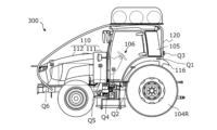
- FIG. 1 is a plan view schematically showing an example of the basic configuration of a work vehicle 100 according to the present disclosure.
- the traveling direction when the work vehicle 100 travels straight ahead will be referred to as the "forward direction”
- the traveling direction when the work vehicle 100 travels straight back will be referred to as the "rear direction”.
- the direction extending perpendicularly to the right with respect to the "front direction” is called the “right direction”
- the direction extending perpendicularly to the left with respect to the "front direction” is called the “left direction”.
- “front”, “back”, “right”, and “left” are indicated by “front”, “rear”, “right”, and “left” arrows, respectively.
- Both the front direction and the rear direction may be collectively referred to as the "front-back direction”
- both the right direction and the left direction may be collectively referred to as the "width direction”.
- the work vehicle 100 in the illustrated example is, for example, a tractor that is an example of an agricultural machine.
- the technology of the present disclosure is not limited to work vehicles such as tractors, but can also be applied to other types of work vehicles.
- the work vehicle 100 can travel within a field while carrying or towing an implement and performing agricultural work according to the type of implement. Further, the work vehicle 100 can also travel within the field and outside the field (including roads) with or without the implement mounted.
- the work vehicle 100 like a conventional tractor, includes a vehicle body (vehicle frame) 102 that rotatably supports left and right front wheels 104F and left and right rear wheels 104R.
- vehicle body 102 includes a front frame 102A provided with a front wheel 104F, and a transmission case 102B provided with a rear wheel 104R.
- Front frame 102A is fixed to the front part of transmission case 102B.
- the front wheel 104F and the rear wheel 104R may be collectively referred to as wheels 104.
- the wheel 104 is a wheel and is equipped with a tire.
- "wheel” basically means “wheels and tires” as a whole.
- One or both of the front wheel 104F and the rear wheel 104R may be replaced with a plurality of wheels (crawlers) equipped with endless tracks instead of wheels with tires.
- the work vehicle 100 in the example of FIG. 1 includes a fuel cell module (FC module) 10 and a motor 70 that are directly or indirectly supported by a front frame 102A.
- the FC module 10 has a fuel cell stack (FC stack), and functions as an on-vehicle generator that generates electric power from fuel, as will be described later.
- FC stack fuel cell stack
- FC stack fuel cell stack
- the motor 70 is electrically connected to the FC module 10.
- the motor 70 can convert the electric power generated by the FC module 10 into mechanical motion (power) and generate the driving force (traction) necessary for the work vehicle 100 to travel.
- An example of motor 70 is an AC synchronous motor. Since the FC stack of the FC module 10 generates DC current, if the motor 70 is an AC synchronous motor, an electric circuit group including an inverter device is provided between the FC stack and the motor 70, so that the DC current is converted to AC. converted into electric current. A part of such an electric circuit group may be inside the FC module 10. Further, another part of the electric circuit group may be attached to the motor 70 as a drive circuit for the motor 70.
- the motor 70 has an output shaft 71 that rotates.
- the torque of the output shaft 71 is transmitted to the rear wheels 104R via mechanical parts such as a transmission (speed change device) provided inside the transmission case 102B and a rear wheel differential device (differential gear device).
- the power generated by the motor 70 which is a power source, is transmitted to the rear wheels 104R by a power transmission system (drive train) 74 including a transmission provided in the transmission case 102B.
- the "transmission case” may also be referred to as the "mission case.”
- a portion of the power of the motor 70 is also transmitted to the front wheels 104F.
- the power of the motor 70 can be used not only for driving the work vehicle 100 but also for driving an implement.
- a power take-off (PTO) shaft 76 is provided at the rear end of the transmission case 102B, and the torque of the output shaft 71 of the motor 70 is transmitted to the PTO shaft 76.
- the implement mounted on or towed by the work vehicle 100 receives power from the PTO shaft 76 and can perform operations according to various tasks.
- the motor 70 and the power transmission system 74 may be collectively referred to as an electric power train.
- An example of the transmission within the transmission case 102B is disclosed in International Publication No. 2022/038860, the entire content of which is incorporated herein.
- the work vehicle 100 is not equipped with an internal combustion engine such as a diesel engine, but is equipped with the FC module 10 and the motor 70. Further, the output shaft 71 of the motor 70 is mechanically coupled to a power transmission system 74 such as a transmission within the transmission case 102B.
- the motor 70 can efficiently generate torque in a relatively wide rotational speed range compared to an internal combustion engine.
- a power transmission system 74 that includes a transmission, it becomes easier to perform multi-stage or continuously variable speed operation to adjust the torque and rotational speed from the motor 70 over a wider range. Therefore, it becomes possible not only to run the work vehicle 100 but also to efficiently perform various tasks using the implement.
- the power transmission system 74 may be deleted depending on the purpose or size of the work vehicle 100. For example, part or all of the transmission responsible for the speed change function may be omitted.
- the number and mounting positions of the motors 70 are also not limited to the example shown in FIG. 1.
- the work vehicle 100 includes at least one fuel tank 50 that stores fuel to be supplied to the FC module 10.
- one fuel tank 50 is shown for simplicity.
- a plurality of fuel tanks 50 are housed in a tank case to constitute a fuel tank module.
- the fuel tank 50 is supported by a member fixed to the vehicle body 102, as will be described later.
- the FC module 10 and the fuel tank 50 are connected by piping, an on-off valve, etc., and form an on-vehicle FC power generation system. The configuration and operation of the FC power generation system will be described later.
- a work vehicle 100 in an embodiment described below includes a driver's seat supported by a vehicle body 102.
- the driver's seat may be surrounded by a cabin supported by the vehicle body 102.
- the FC module 10 is placed in front of the driver's seat, and the fuel tank 50 is placed above the driver's seat.
- the FC module 10 and fuel tank 50 are housed in at least one "container".
- the "container" functions, for example, as a housing, and serves to protect the FC module 10 and the fuel tank 50 from sunlight and wind and rain.
- such a container can also control the spread of the fuel gas into the atmosphere and facilitate the detection of the fuel gas when the fuel gas leaks from the FC module 10 or the fuel tank 50.
- the FC module 10 may be housed in a front housing called a "bonnet", for example.
- the front housing is part of the "container”.
- the front housing is supported by the front portion of the vehicle body 102 (front frame 102A).
- the fuel tank 50 may be housed in a tank case as described above.
- the tank case is directly or indirectly supported by the vehicle body 102.
- FC power generation system 180 mounted on the work vehicle 100.
- the FC power generation system 180 shown in FIG. 2 functions as an on-vehicle power generation system in the work vehicle 100 of FIG. 1.
- the electric power generated by the FC power generation system 180 is used not only for driving the work vehicle 100 but also for operating the implement towed or attached to the work vehicle 100.
- the FC power generation system 180 in the illustrated example includes an FC module 10 and at least one fuel tank 50 that accommodates fuel to be supplied to the FC module 10.
- the FC power generation system 180 also includes a radiator device 34 for cooling the FC module 10.
- the FC module 10 includes a fuel cell stack (FC stack) 11, an air compressor 12, a fuel circulation pump 24, a coolant pump 31, a booster circuit 40, and a control device 42 as main components. It is equipped with These components are housed within the casing of the FC module 10 and are connected to each other through electrical or fluid communication.
- the FC stack 11 generates electricity through an electrochemical reaction between "anode gas” which is a fuel and "cathode gas” which is an oxidizing gas.
- the FC stack 11 in this example is a polymer electrolyte fuel cell.
- the FC stack 11 has a stack structure in which a plurality of single cells are stacked.
- a single cell includes, for example, an electrolyte membrane formed from an ion exchange membrane, an anode electrode formed on one surface of the electrolyte membrane, a cathode electrode formed on the other surface of the electrolyte membrane, and an anode electrode and a cathode electrode. It is equipped with a pair of separators sandwiched from both sides.
- the voltage generated in a single cell is, for example, 1 volt or less. For this reason, in the FC stack 11, for example, 300 or more single cells are connected in series to generate a voltage of several hundred volts.
- An anode gas is supplied to the anode electrode of the FC stack 11.
- the anode gas is called "fuel gas” or simply “fuel.”
- the anode gas (fuel) is hydrogen gas.
- Cathode gas is supplied to the cathode electrode.
- the cathode gas is an oxidizing gas such as air.
- the anode electrode is called the fuel electrode, and the cathode electrode is called the air electrode.
- anode off gas The anode gas after being used in the above reaction is referred to as "anode off gas", and the cathode gas after being used in reaction is referred to as “cathode off gas”.
- the air compressor 12 supplies air taken in from the outside to the cathode electrode of the FC stack 11 as cathode gas.
- the cathode gas supply system including the air compressor 12 has a cathode gas supply pipe 13 , a cathode off-gas pipe 14 , and a bypass pipe 15 .
- the cathode gas supply pipe 13 allows cathode gas (air) supplied from the air compressor 12 to flow to the cathode electrode of the FC stack 11 .
- the cathode off-gas pipe 14 allows cathode off-gas discharged from the FC stack 11 to flow to the outside air.
- the bypass pipe 15 branches from the cathode gas supply pipe 13 downstream of the air compressor 12, bypasses the FC stack 11, and is connected to the cathode off-gas pipe 14.
- the bypass pipe 15 is provided with a control valve 16 that adjusts the flow rate of cathode gas flowing into the bypass pipe 15 .
- the cathode gas supply pipe 13 is provided with a cutoff valve 17 that selectively blocks the inflow of cathode gas into the FC stack 11 .
- the cathode off-gas pipe 14 is provided with a pressure regulating valve 18 that adjusts the back pressure of the cathode gas.
- the cathode gas supply system of the FC module 10 is provided with a rotation speed detection sensor S1 that detects the rotation speed of the air compressor 12, and a gas flow rate detection sensor S2 that detects the flow rate of the cathode gas flowing into the cathode gas supply pipe 13. ing.
- the control valve 16, the cutoff valve 17, and the pressure regulating valve 18 are, for example, electromagnetic valves.
- the fuel circulation pump 24 supplies the fuel gas (anode gas) sent from the fuel tank 50 to the anode electrode of the FC stack 11.
- the anode gas supply system including the fuel circulation pump 24 has an anode gas supply pipe 21 , an anode off-gas pipe 22 , and a circulation flow path 23 .
- the anode gas supply pipe 21 allows the anode gas supplied from the fuel tank 50 to flow to the anode electrode of the FC stack 11 .
- the fuel tank 50 in the embodiment of the present disclosure is a hydrogen tank that stores high-pressure hydrogen gas.
- the anode off-gas pipe 22 allows the anode off-gas discharged from the FC stack 11 to flow.
- the anode off-gas is led to the gas-liquid separator 25 through the anode off-gas pipe 22, where water is removed.
- the anode off-gas from which moisture has been removed is returned to the anode gas supply pipe 21 through the circulation passage 23 by the fuel circulation pump 24 .
- the anode off-gas circulating in the circulation channel 23 can be discharged through the anode off-gas pipe 22 by opening the exhaust valve 26 .
- Moisture stored in the gas-liquid separator 25 can be discharged through the anode off-gas pipe 22 by opening the exhaust valve 26.
- the exhaust valve 26 is, for example, a solenoid valve.
- the anode off-gas pipe 22 is connected to the cathode off-gas pipe 14.
- the anode off-gas containing unreacted anode gas that did not contribute to the electrochemical reaction is circulated and supplied to the FC stack 11 again, thereby improving the utilization efficiency of the anode gas. is possible.
- FIG. 2 shows a coolant circulation system including a coolant pump 31 for the FC stack 11, cooling circulation systems for other electrical components may also be provided, as will be described later.
- the air compressor 12, fuel circulation pump 24, and coolant pump 31 included in the FC module 10 are each operated by a built-in motor. These motors are also electrical components.
- the coolant circulation system including the coolant pump 31 in FIG. 2 includes a coolant supply pipe 32, a coolant discharge pipe 33, a radiator device 34, and a temperature sensor S3.
- This coolant circulation system can adjust the temperature of the FC stack 11 within a predetermined range by circulating the coolant through the FC stack 11. Coolant is supplied to the FC stack 11 through the coolant supply pipe 32. The supplied coolant flows through the coolant flow path formed between the single cells and is discharged to the coolant discharge pipe 33. The coolant discharged to the coolant discharge pipe 33 flows to the radiator device 34.
- the radiator device 34 radiates heat from the coolant by exchanging heat between the inflowing coolant and the outside air, and supplies the coolant whose temperature has decreased to the coolant supply pipe 32 again.
- the coolant pump 31 is installed in the coolant supply pipe 32 or the coolant discharge pipe 33 so as to send the coolant to the FC stack 11.
- a coolant bypass flow path may be provided between the coolant discharge pipe 33 and the coolant supply pipe 32.
- a branch valve is provided at the branch point where the coolant bypass flow path branches from the coolant discharge pipe 33.
- the diverter valve can adjust the flow rate of the coolant flowing into the bypass channel.
- the temperature sensor S3 detects the temperature of the coolant flowing through the coolant discharge pipe 33.
- the coolant used to cool the FC stack 11 is circulated through the flow path by a coolant electric pump (coolant pump) 31.
- a coolant control valve may be provided downstream of the FC stack 11. The coolant control valve adjusts the ratio of coolant flowing to the radiator device 34 and coolant bypassing the radiator device 34, allowing the temperature of the coolant to be controlled with greater accuracy. Furthermore, by controlling the amount of water fed by the coolant pump, it is also possible to control the coolant temperature difference between the inlet and outlet of the FC stack 11 to fall within a desired range.
- the temperature of the coolant in the FC stack 11 can be controlled to a temperature at which the power generation efficiency of the FC stack 11 is high, for example, about 70°C.
- the coolant flowing through the FC stack 11 has higher insulating properties than the coolant used to cool ordinary electrical components. Since a high voltage exceeding, for example, 300 volts is generated in the FC stack 11, by increasing the electrical resistance of the coolant, current leakage through the coolant or the radiator device 34 can be suppressed. As the use of the coolant progresses, the electrical resistance of the coolant may decrease. This is because ions dissolve into the coolant flowing through the FC stack 11. In order to remove such ions from the coolant and improve insulation, it is desirable that an ion exchanger be disposed in the flow path of the coolant.
- the boost circuit 40 can increase the voltage output from the FC stack 11 through power generation operation to a desired level.
- the subsequent stage of the booster circuit 40 is connected to a heavy-duty electric circuit including an inverter device for driving the motor. Note that, as will be described later, the subsequent stage of the booster circuit 40 can also be connected in parallel to a weak electric system electric circuit via a step-down circuit.
- the control device 42 is an electronic control unit (ECU) that controls power generation by the FC module 10.
- the control device 42 detects or estimates the operating state of the FC power generation system 180 based on signals output from various sensors.
- the control device 42 controls the operation of the air compressor 12, fuel circulation pump 24, coolant pump 31, and various valves based on the operating state of the FC power generation system 180 and commands output from a host computer or other ECU. is controlled to control power generation by the FC stack 11.
- the control device 42 includes, for example, a processor, a storage device, and an input/output interface.
- anode gas will be referred to as "fuel gas” or "fuel”
- the “anode gas supply pipe” will be referred to as "piping”.
- FIG. 3 is a block diagram schematically showing an example of electrical connections and power transmission between components of work vehicle 100 according to the present disclosure.
- FIG. 4 is a block diagram showing a more detailed configuration than the example configuration shown in FIG. FIG. 4 schematically shows electrical signal paths (thin solid lines) and coolant paths (dotted lines) between components in work vehicle 100.
- Electrical connections include both high-power and low-power systems.
- the electrical connection of the high-voltage system provides, for example, the power supply voltage of the inverter device.
- Low-voltage electrical connections provide, for example, a power supply voltage for electronic components that operate at relatively low voltages.
- the work vehicle 100 includes an FC module 10, an inverter device 72, a motor 70, a power transmission system 74, and a PTO shaft 76.
- the DC voltage of the power generated in the FC stack 11 of the FC module 10 is boosted by the booster circuit 40 and then supplied to the inverter device 72 .
- Inverter device 72 converts DC voltage into, for example, three-phase AC voltage and supplies it to motor 70 .
- Inverter device 72 has a bridge circuit including a plurality of power transistors.
- Motor 70 has a rotating rotor and a stator having a plurality of coils electrically connected to inverter device 72.
- the rotor is coupled to the output shaft 71, for example, via a reduction gear (speed reducer) or directly.
- the motor 70 rotates the output shaft 71 with torque and rotational speed controlled according to the waveform of the three-phase AC voltage from the inverter device 72.
- the torque of the output shaft 71 of the motor 70 is transmitted to the power transmission system 74.
- the power transmission system 74 operates using the motor 70 as a power source, and can drive the wheels 104R, 104F and/or the PTO shaft 76 in FIG.
- Such a drive train 74 may have a similar or similar structure to a drive train in a conventional tractor with an internal combustion engine, such as a diesel engine.
- an internal combustion engine such as a diesel engine.
- the power transmission system 74 includes a driving system power transmission mechanism that transmits the power from the motor 70 to the left and right rear wheels 104R via a clutch, a transmission, a rear wheel differential, etc., and a drive system power transmission mechanism that transmits the power from the motor 70 to the left and right rear wheels 104R via a clutch, a transmission, a rear wheel differential, etc. and a PTO system power transmission mechanism.
- the transmission case 102B in FIG. 1 may be divided into a front case (mission case) that houses a clutch, a transmission, and the like, and a rear case (differential gear case) that houses a rear wheel differential and the like.
- the rear case is also called the rear axle case.
- the work vehicle 100 includes a secondary battery (battery pack) 80 that temporarily stores electrical energy generated by the FC module 10.
- battery packs 80 include lithium ion battery packs.
- the battery pack 80 can supply power to the inverter device 72 at the required timing, either in cooperation with the FC module 10 or alone. As the battery pack 80, it is possible to employ various battery packs used in passenger electric vehicles.
- the work vehicle 100 includes various electrical components (vehicle-mounted electronic components) that operate using electricity.
- electrical components include electromagnetic valves such as the on-off valve 20, an air cooling fan of the radiator device 34, an electric pump of the cooling compressor 85, and a temperature control device that heats or cools the FC stack 11.
- a temperature control device includes an electric heater 86.
- DC-DC converters 81 and 82 and a storage battery 83 for obtaining a power supply voltage suitable for operation of these electrical components may also be included in the electrical components.
- various electronic components (such as a lamp, a hydraulic electric motor, etc.) that are not shown may also be included in the electrical components. These electrical components may be, for example, electronic components similar to electrical components installed in conventional agricultural tractors.
- the first DC-DC converter 81 is a circuit that steps down the voltage output from the booster circuit 40 of the FC module 10 to a first voltage, for example, 12 volts.
- the storage battery 83 is, for example, a lead storage battery, and can store electrical energy using the voltage output from the first DC-DC converter 81.
- the storage battery 83 can be used as a power source for various electrical components such as a lamp.
- the work vehicle 100 shown in FIG. 3 includes not only a first DC-DC converter 81 but also a second DC-DC converter 82 as a voltage conversion circuit that steps down the high voltage output by the FC module 10.
- the second DC-DC converter 82 is a circuit that steps down the voltage (for example, several hundred volts) output from the booster circuit 40 of the FC module 10 to a second voltage, for example, 24 volts, which is higher than the first voltage.
- the air cooling fan of the radiator device 34 can be operated using the voltage output from the second DC-DC converter 82, for example.
- the radiator device 34 is illustrated as a single component in FIG. 3, one work vehicle 100 may include a plurality of radiator devices 34.
- the electric pump of the cooling compressor 85 and the electric heater 86 can also be operated with the voltage output from the second DC-DC converter 82.
- the work vehicle 100 shown in FIG. 3 is equipped with a temperature control device that cools or heats the FC stack 11 included in the FC power generation system. Relatively large amounts of electrical power are required to operate such temperature control devices.
- the relatively high 24 volt voltage output by the second DC-DC converter 82 is provided to such a temperature control device.
- the temperature control device in this embodiment includes a radiator device 34 that radiates heat from the refrigerant that cools the FC stack 11, and the relatively high second voltage of 24 volts output by the second DC-DC converter 82 is radiator device 34.
- the temperature control device includes a heater 86 that heats the FC stack 11.
- the relatively high voltage output by the second DC-DC converter 82 may also be applied to the heater.
- the relatively high voltage output by the second DC-DC converter 82 may also be applied to an air conditioner such as the cooling compressor 85, for example.
- the work vehicle 100 may include a third voltage conversion circuit that converts the high voltage output by the FC module 10 into a third voltage higher than the second voltage.
- the third voltage is, for example, 48 volts.
- the work vehicle 100 includes another motor apart from the motor 70, the third voltage may be used as a power source for the other motor, for example.
- Agricultural work vehicles equipped with fuel cell power generation systems are equipped with electrical components necessary for fuel cell power generation operation in addition to the electrical components necessary for agricultural work, so the voltage level suitable for each electrical component may differ. . According to embodiments of the present disclosure, it is possible to supply a voltage of an appropriate magnitude.
- a plurality of fuel tanks 50 are housed in one tank case 51.
- the fuel tank 50 is connected to a filling port (fuel filling port) 52 that is filled with fuel from the outside. This connection is made by a pipe 21 for flowing fuel gas.
- the fuel tank 50 is connected to the FC module 10 via a pipe 21 provided with an on-off valve 20.
- these pipes 21 may be formed from a material with high resistance to hydrogen embrittlement, for example, austenitic stainless steel such as SUS316L.
- the tank case 51 is provided with a valve space 53, and various valves including a pressure reducing valve are arranged within this valve space 53.
- the pipe 21 connects the fuel tank 50 and the FC module 10 via various valves provided in the valve space 53.
- Fuel gas whose pressure has been reduced by the pressure reducing valve flows through the pipe 21 that connects the tank case 51 and the FC module 10 .
- the fuel tank 50 may be filled with high-pressure hydrogen gas of, for example, 35 megapascals or more, but after passing through a pressure reducing valve, the hydrogen gas is depressurized to, for example, about 2 atmospheres or less. can be done.
- FIG. 4 also shows a plurality of ECUs that communicate within the work vehicle 100 and a user interface 1. Communication may be performed via CAN bus wiring, etc., which serves as a path (thin solid line) for electrical signals. Also shown in FIG. 4 is a cooling system for providing thermal management of the components. Specifically, the coolant path (dotted line) is schematically shown.
- the first and second DC-DC converters 81 and 82 can each output voltages of different magnitudes. These first and second DC-DC converters 81 and 82 are also provided with ECUs that control their respective voltage conversion circuits. These ECUs, like other ECUs, are given a relatively low first voltage output from the first DC-DC converter 81.
- the work vehicle 100 is equipped with a cooling system in which coolant is circulated by coolant pumps 31A and 31B. These coolant pumps 31A and 31B are provided inside the FC module 10.
- the cooling system in this example includes a first radiator device 34A that is responsible for cooling the FC stack 11, and a second radiator device 34B that is responsible for cooling other electrical components.
- the cooling system has a flow path (first flow path) through which a cooling liquid flows between the FC stack 11 and the first radiator device 34A. Further, this cooling system has a flow path (second flow path) through which the cooling liquid flows between the electrical components including the motor 70 and the second radiator device 34B.
- a heater core 87 used for heating the cabin is provided, and the coolant flowing through the first radiator device 34A flows through this heater core 87.
- the user interface 1 includes an operating device 2 such as an accelerator pedal (or accelerator lever), and a main ECU 3 connected to the operating device 2.
- Main ECU 3 is connected to main meter 4.
- the main meter 4 can display various parameters that specify the running state or operating state of the work vehicle 100.
- the user interface 1 further includes an FC system ECU 5 for controlling the FC power generation system.
- the FC system ECU 5 is connected to the FC meter 6.
- the FC meter 6 can display various parameters that specify the operating state of the FC power generation system.
- the cells of the battery pack 80 are controlled by a battery management unit (BMU).
- BMU battery management unit
- the BMU includes a circuit that monitors the voltage of each battery cell, monitors overcharging and overdischarging, and performs cell balance control, and a CPU (Central Processing Unit). These circuits and the CPU may be mounted on the battery controller board.
- FIG. 5 is a side view schematically showing a configuration example of the work vehicle 200 in this embodiment.
- FIG. 6A is a side view schematically showing an example of the arrangement of main parts of work vehicle 200, and FIG. 6B is a plan view thereof.
- FIG. 7 is a diagram schematically showing a mechanism that supports the fuel tank 50.
- the work vehicle 200 in this embodiment includes an FC module 10, a fuel tank 50, a motor 70, a driver's seat 107, and a vehicle body 102.
- Work vehicle 200 has a configuration similar to that of work vehicle 100 described with reference to FIG.
- the fuel tank 50 is supported by a fixed frame 120.
- the fixed frame 120 is fixed to the vehicle body 102 across the driver's seat 107.
- the structure and function of the fixed frame 120 make it possible to stably support the fuel tank 50 above the driver's seat 107.
- the degree of freedom in arranging components such as the FC module 10 and the motor 70 supported by the vehicle body 102 increases. It also reduces the need to significantly modify the structure of conventional engine-driven tractors. These things contribute to lower design and manufacturing costs.
- the fixed frame 120 is a long axis-shaped structure such as a pipe that is fixed to the vehicle body 102.
- the fixed frame 120 has a front part 120A, a middle part 120B, and a rear part 120C, as shown in FIG. 6A.
- the front portion 120A has a curved shape and is connected to the middle portion 120B.
- the intermediate portion 120B has a shape that extends linearly in the front-rear direction, and is connected to the rear portion 120C.
- the rear portion 120C has a shape that extends linearly in the vertical direction. Note that the illustrated shape of the fixed frame 120 is only an example, and the shape of the fixed frame 120 is not limited to this example.
- the vehicle body 102 includes a front frame 102A that rotatably supports a front wheel 104F, and a transmission case 102B that rotatably supports a rear wheel 104R.
- one end (front end) 128 of the fixed frame 120 is fixed to the front frame 102A.
- the other end (rear end) 129 of the fixed frame 120 is fixed to the transmission case 102B.
- fixations may be made by any suitable method, such as welding or bolting, depending on the material of the fixation frame 120.
- the fixed frame 120 may be formed from, for example, metal, synthetic resin, carbon fiber, or a composite material such as carbon fiber reinforced plastic or glass fiber reinforced plastic.
- the transmission case 102B includes a rear axle case, and the rear end 129 of the fixed frame 120 may be fixed to the rear axle case. Note that when the fixed frame 120 is made of metal, part or all of its surface may be covered with synthetic resin.
- the fixed frame 120 is required to have sufficient rigidity to support the fuel tank 50.
- the fuel tank 50 supported by the fixed frame 120 may vibrate up and down, back and forth, left and right. Due to the elastic deformation of the fixed frame 120, part or all of the fixed frame 120 is appropriately bent, so that the impact on the fuel tank 50 is alleviated.
- the front portion 120A of the fixed frame 120 has a curved shape and allows deformation within a predetermined range.
- Part or all of the rear portion 120C of the fixed frame 120 may have a curved or inclined shape.
- the external shape of the cross section perpendicular to the long axis direction of the fixed frame 120 is, for example, a circle or an ellipse, but is not limited thereto.
- the outer shape of the cross section may be a quadrilateral or other polygon.
- the fixed frame 120 has a generally cylindrical or cylindrical shape, its outer diameter is, for example, in a range of 10 mm or more and 100 mm or less. Further, the inner diameter may be 0% or more and 90% or less of the outer diameter.
- the work vehicle 200 includes a cabin 105 surrounding a driver's seat 107 between the vehicle body 102 and the fixed frame 120.
- the driver's seat 107 is located at the rear of the cabin 105 (referred to as "cabin interior").
- a steering handle (steering wheel) 106 is provided in front of the driver's seat 107, for example, for changing the direction of the front wheels 104F.
- Cabin 105 has a cabin frame that constitutes a skeleton.
- a roof 109 is provided on the top of the cabin frame.
- the cabin frame of this embodiment is a four-poster type.
- Cabin 105 is supported by transmission case 102B of vehicle body 102, for example via a vibration-proof mount.
- the interface 1 described with reference to FIG. 4 is provided inside the cabin 105. Since the cabin 105 does not directly support the fuel tank 50, there is no need to particularly increase its strength, and a cabin that has been used in conventional tractors can be used.
- the intermediate portion 120B of the fixed frame 120 extends in the front-rear direction along the roof 109 of the cabin 105, and functions as a support for the fuel tank 50.
- the fuel tank 50 is supported by the intermediate portion 120B of the fixed frame 120 above the roof 109 of the cabin 105.
- the fixed frame 120 includes not one frame but two frames located on the left and right sides of the work vehicle 200.
- the left and right fixed frames 120 extend parallel to the front-rear direction of the work vehicle 200.
- the two fixed frames 120 are positioned so as to avoid the central area of the visual field of the operator seated in the driver's seat 107 and looking forward.
- the number of fixed frames 120 may be one, or three or more. It is desirable that the fixed frame 120 be provided at a position that avoids the central area of the visual field of the operator seated in the driver's seat 107 and looking forward, and that it supports the fuel tank 50 in a well-balanced manner. From this point of view, it is desirable that the number of fixed frames 120 is an even number.
- each fixed frame 120 passes directly above the driver's seat in a plan view looking down from directly above.
- the fixed frame is fixed to the vehicle body "straddling the driver's seat", as shown in FIG. , or it means that it extends above the cabin 105 along the front-rear direction.
- the two fixed frames 120 are parallel to each other, but the interval between the fixed frames 120 does not need to be constant along the front-rear direction and may vary.
- the work vehicle 200 includes a mounting table 51A that connects the left frame 120 and the right frame 120.
- the fuel tank 50 may be placed on the mounting table 51A. If there is a plurality of fuel tanks 50, the plurality of fuel tanks 50 may be included in the fuel tank module.
- the fuel tank module includes a tank case 51 that accommodates a plurality of fuel tanks 50 (FIG. 5).
- the left and right fixed frames 120 may be connected to each other by a member other than the mounting table 51A.
- a coupling device 108 is provided at the rear end of the transmission case 102B, which is the rear portion of the vehicle body 102.
- the coupling device 108 includes, for example, a three-point support device (also referred to as a "three-point link” or “three-point hitch”), a PTO shaft, a universal joint, and a communication cable.
- the implement 190 can be attached to and detached from the work vehicle 200 by the coupling device 108.
- the coupling device 108 can change the position or posture of the implement 190 by raising and lowering the three-point link using, for example, a hydraulic device.
- power can be sent from the work vehicle 200 to the implement 190 via the universal joint.
- the work vehicle 200 can cause the implement 190 to perform a predetermined work (agricultural work) while pulling the implement 190.
- the coupling device 108 may be provided at the front of the vehicle body 102. In that case, the implement 190 can be connected to the front of the work vehicle 200.
- the mounting table 51A for the fuel tank 50 is fixed to the intermediate portion 120B of the fixed frame 120. This fixation may be achieved, for example, by a coupling 127, such as a pipe fitting.
- the fuel tank 50 is fixed to the mounting table 51A by, for example, a fixing belt 56.
- a cover 51B is removably or openably attached to the mounting table 51A so as to cover the fuel tank 50.
- the tank case 51 in this example is composed of a mounting table 51A and a cover 51B.
- the tank case 51 functions as a part of at least one container that houses the FC module 10 and the fuel tank 50.
- the cover 51B in this embodiment has a curved surface portion 51C that connects from the top surface portion 51T to the surrounding side surface portion 51S.
- the height of the cover 51B is highest at the top surface portion 51T, and the height of the curved surface portion 51C decreases as it approaches the side surface portion 51S.
- the tank case 51 may be provided with an opening for exhausting fuel gas leaking inside the tank case 51 to the outside.
- the tank case 51 may be formed from metal, synthetic resin, carbon fiber, or a composite material such as carbon fiber reinforced plastic or glass fiber reinforced plastic.
- the fuel tank 50 is connected to a pipe 21 for flowing fuel gas through a valve 57 such as a pressure reducing valve and an electromagnetic valve.
- the piping 21 inside the tank case 51 is connected to the piping 21 outside the tank case 51, for example, through an opening provided in the mounting table 51A.
- a part of the piping 21 outside the tank case 51 is provided inside the intermediate portion 120B of the fixed frame 120.
- a portion of the pipe 21 connecting the fuel tank 50 and the FC module 10 is located inside the fixed frame 120.
- the piping 21 connecting the tank case 51 and the FC module 10 is configured to allow fuel whose pressure has been reduced by a pressure reduction valve to pass therethrough.
- a wiring cable is connected to a valve 57 such as an electromagnetic valve. Some or all of such distribution cables may pass through the interior of the fixed frame 120.
- the piping 21 or the wiring cable may be arranged along the outer surface of the fixed frame 120 instead of inside the fixed frame 120. However, it is preferable to arrange it inside the fixed frame 120 because the fixed frame 120 having rigidity exhibits the function of protecting the piping 21 and the wiring cable.
- the fixed frame 120 does not need to be fixed to the roof 109 of the cabin 105. As shown in FIG. 7, a gap may exist between the roof 109 of the cabin 105 and the intermediate portion 120B of the fixed frame 120. When the work vehicle 200 is traveling on uneven ground, the vertical vibrations of the cabin 105 and the vertical vibrations of the tank case 51 supported by the fixed frame 120 do not need to match in amplitude and frequency.
- a damper 54 is provided between the roof 109 and the mounting table 51A. Such a damper 54 prevents the mounting table 51A from colliding with the roof 109 even when the work vehicle 200 moves up and down significantly.
- the rear portion 120C of the fixed frame 120 supports the mounting table 51A in a vertically extending state (FIGS. 5 and 6A).
- the rear portion 120C of the fixed frame 120 is made of a material such as metal that is difficult to expand and contract in the longitudinal direction, the rear portion 120C functions to suppress vertical movement of the mounting table 51A with respect to the vehicle body 102.
- the vibration of the cabin 105 relative to the vehicle body 102 may behave differently from the vibration of the mounting table 51A relative to the vehicle body 102.
- the coupled vibration of the cabin 105 and the fuel tank 50 can be controlled by adjusting the damping ratio of the damper 54.
- the type, number, and position of the dampers 54 may be determined by taking into consideration the size and weight of the tank case 51.
- the cabin 105 and the mounting table 51A may be coupled by an elastic member such as a spring or rubber.
- the damper 54 and/or the elastic member may be arranged to connect the intermediate portion 120B of the fixed frame 120 to the cabin 105 instead of the mounting table 51A.
- the cabin 105 and the fuel tank 50 move or vibrate as one during driving.
- the cabin 105 and the fuel tank 50 in order to allow a certain degree of freedom of movement between the cabin 105 and the fuel tank 50, it is possible to separate the vibration mode of the cabin 105 and the vibration mode of the fuel tank 50. It becomes possible. This results, for example, in a soundproofing effect in the cabin interior.
- a fuel filling port connected to the piping 21 may be provided in the fixed frame 120. (The details of the fuel filling port 52 (FIGS. 3 and 4) will be described later.)
- the fuel tank module 55 in the example of FIG. 8 includes a plurality of fuel tanks 50, a valve system 58 connected to the plurality of fuel tanks 50, and a tank case 51 housing the plurality of fuel tanks 50 and the valve system 58.
- the valve system 58 includes an on-off valve and a pressure reducing valve located inside the tank case 51. Further, the valve system 58 housed in the tank case 51 may further include a check valve, a filter, a safety valve, a pressure sensor, and a dissipation pipe. These devices included in the valve system 58 are connected by high pressure or low pressure piping.
- the tank case 51 has a bottom plate that extends along a plane (XY plane) defined by the X-axis direction (first direction) and the Y-axis direction (second direction), and the plurality of fuel tanks 50 are arranged on the bottom plate.
- the mounting table 51A also serves as the bottom plate. Note that the shape of the mounting table 51A does not need to be a flat plate, and may have ridges or grooves to increase strength. Further, the mounting table 51A may have a convex portion, a concave portion, and/or an opening hole for fixing other parts such as the fuel tank 50, the cover 51B, and the valve.
- Each of the plurality of fuel tanks 50 in this embodiment is a high-pressure hydrogen tank having a cylindrical portion extending in the X-axis direction.
- the outer diameter of the cylindrical portion may be, for example, around 300 mm.
- An example of the fuel tank 50 is a high-pressure hydrogen tank made of resin, and may be formed from a multilayer structure in which a resin liner, carbon fiber reinforced plastic, and glass fiber reinforced plastic are laminated.
- the plurality of fuel tanks 50 include a first fuel tank 50A having a first length L1 in the X-axis direction, and a second length L2 in the X-axis direction that is shorter than the first length L1. and a third fuel tank 50C having a third length L3 shorter than the first length L1 in the X-axis direction. Note that in other embodiments of the present disclosure, it is not necessary to include the third fuel tank 50C, and other fuel tanks may be included.
- the number of fuel tanks 50 included in one fuel tank module 55 is not limited to three, but may be more than one. Further, in the example of FIG. 8, the third length L3 is equal to the second length L2, but the third length L3 may be different from the second length L2.
- the first fuel tank 50A, the second fuel tank 50B, and the third fuel tank 50C are arranged (lined up) in the Y-axis direction perpendicular to the X-axis direction. At least a portion of the valve system 58 is disposed within the tank case 51 in a space formed between the second fuel tank 50B and the tank case 51. Further, at least another part of the valve system 58 is disposed within the tank case 51 in a space formed between the third fuel tank 50C and the tank case 51. In other words, the valve system 58 is arranged in the valve space 53 in the space from the second fuel tank 50B and the third fuel tank 50C to the tank case 51.
- valve space 53 By housing the fuel tanks 50 having different lengths in the tank case 51, a space suitable for accommodating parts can be formed in the tank case 51, and this space can be used as the valve space 53. It becomes possible to do so.
- valve space 53 including for example on-off valves and pressure reducing valves, it is possible to enhance the functionality of the fuel tank module 55. Specifically, the pressure of the fuel can be lowered from, for example, 35 megapascals to several atmospheres by the function of a pressure reducing valve inside the tank case 51, and then the fuel can be taken out of the tank case 51. As a result, there is no need to use expensive piping for high-pressure hydrogen gas as the piping 21 for connecting the tank case 51 and the FC module 10.
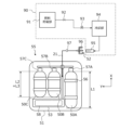
- the fuel filling device 90 includes a fuel storage section 91, a cutoff valve 92, a regulator 93, a cooling section 94, and a dispenser nozzle 95.
- the fuel filling device 90 may be installed at a specific site or may be mounted on a moving body such as a truck to function as a mobile station.
- a dispenser nozzle 95 of the fuel filling device 90 is connected to a cooling unit 94 via a flexible fuel hose. After the worker who fills the fuel inserts the dispenser nozzle 95 into the fuel filling port 52 of the work vehicle 200, filling of the fuel (high-pressure hydrogen gas) is started.
- the fuel filling port 52 of the work vehicle 200 has a receptacle 96 that receives fuel from the dispenser nozzle 95 of the fuel filling device 90.
- the receptacle 96 is inserted into an opening provided at the tip of the dispenser nozzle 95 when the dispenser nozzle 95 is inserted into the fuel filling port 52 .
- the fuel injected into the receptacle 96 from the dispenser nozzle 95 is supplied to the fuel tanks 50A, 50B, and 50C arranged in the tank case 51 of the fuel tank module 55 through the pipe 21 in which a check valve 97 is provided in the middle. be done.
- Fuel tanks 50A, 50B, and 50C are connected to piping 21 via electromagnetic valves 57A, 57B, and 57C, respectively.
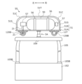
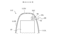
- FIG. 9 is a diagram schematically showing the flow of fuel (hydrogen) gas leaking inside the front housing 110 and tank case 51 that function as such containers.
- the flow of leaked fuel gas is schematically represented by dotted arrows.
- Such fuel gas leakage may occur from the FC module 10, the fuel tank 50, the valve system 58, the piping 21, and the like.
- the pipe 21 connecting the fuel tank 50 and the FC module 10 is inserted into the front housing 110 through the fixed frame 120.
- the work vehicle 200 in this embodiment includes at least one fuel gas sensor provided inside the housing.
- the fuel gas is hydrogen gas
- examples of fuel gas sensors may include hydrogen gas sensors that operate in various ways, such as a catalytic combustion type, a gas heat conduction type, a solid electrochemical type, and a semiconductor type.
- the fuel gas sensor detects a fuel gas leak, notification/warning to the driver, fail-safe control or operation stoppage of the FC power generation system, etc. may be executed depending on the concentration level of the leaked fuel gas.
- the housing body in this embodiment that is, the front housing 110 and the tank case 51, each has a shape and structure that controls the spread of hydrogen gas leaking inside it into the atmosphere and facilitates the detection of hydrogen gas. are doing.
- the upper surface 110T of the front housing 110 has a shape that becomes higher gradually or stepwise from the front end side of the work vehicle 200 toward the rear. Since the hydrogen gas leaking inside the front housing 110 is lighter than air, it flows rearward along the upper surface 110T of the front housing 110 and approaches the front surface 105F of the cabin 105. Further, a portion of the fuel gas leaking from the piping 21 in the front housing 110 or the connection between the FC module 10 and the piping 21 may rise along the front surface 105F of the cabin 105.
- the width of the front housing 110 is designed to be narrower than the distance between the front wheels 104F. This is different from the case where the hood of a passenger car covers the left and right front wheels, and the width of the hood is wider than the distance between the front wheels.
- the width of the front housing 110 narrower than the distance between the front wheels 104F, the volume of the front housing 110 can be made relatively small. By reducing the volume of the front housing 110, it becomes possible to easily detect the leaked hydrogen gas with the fuel gas sensor before it is diluted.
- the height of the tank case 51 in this embodiment is highest at the top surface portion 51T, and the height of the curved surface portion 51C decreases as it approaches the side surface portion 51S. Therefore, hydrogen gas leaking inside the tank case 51 tends to collect in the upper part of the tank case 51 inside the peripheral area.
- the tank case 51 in this embodiment is provided at a higher position than the front housing 110 at the rear of the front housing 110. Therefore, when the front housing 110 and the tank case 51 are in communication through the piping 21, hydrogen gas leaking inside the front housing 110 may enter the inside of the tank case 51 through some route. .
- the tank case 51 is located at the highest position. For this reason, when the containers form a communicating space, hydrogen gas leaking inside the container will be absorbed into the tank case 51, more specifically, the highest part of the container. They tend to gather near the upper surface 51T of the tank case 51.
- the fuel gas sensor includes a first sensor 45 provided inside the front housing 110 and a second sensor 46 provided inside the tank case.
- the first sensor 45 is disposed inside the front housing 110 in a relatively high area, that is, in an area where fuel gas gathers. Specifically, it is provided inside the front housing 110 in a region where the front surface 105F of the cabin 105 and the upper surface 110T of the front housing 110 are close to each other.
- the second sensor 46 is provided inside the tank case 51 at a higher position than the valve system 58, preferably below the upper surface portion 51T of the tank case 51. The second sensor 46 is provided at a higher position than the first sensor 45, and functions as a fuel gas sensor provided at the highest position in the work vehicle 200.
- FIGS. 10 and 11 are a side view and a plan view, respectively, schematically showing an arrangement example of the radiator device in this embodiment.
- the work vehicle 200 in this embodiment includes a cooling system in which the coolant is circulated by the coolant pumps 31A and 31B shown in FIG.
- the work vehicle 200 includes a first radiator device 34A disposed on one side (backward) of the FC module 10, and a first radiator device 34A disposed on the other side (front) of the FC module 10. and a second radiator device 34B disposed in the second radiator device 34B.
- the first radiator device 34A is connected to a flow path (first flow path) for cooling the FC stack 11 (see FIG. 4) included in the FC module 10.
- the second radiator device 34B is connected to a flow path (second flow path) for cooling electrical components including the motor 70.
- the cooling system in the work vehicle 200 of this embodiment includes the first radiator device 34A that is responsible for cooling the FC stack 11, and the second radiator device 34B that is responsible for cooling other electrical components. . It is desirable that the ability to cool the FC stack 11 increases the ability to cool other electrical components. In order to increase the cooling capacity of a radiator device, it is required to increase the area of the front surface of the radiator device and increase the area (core size) where the core portion of the heat exchanger contacts the air.
- the front surface area of the first radiator device 34A is made larger than the front surface area of the second radiator device 34B.
- the width W1 of the first radiator device 34A is larger than the width W2 of the second radiator device 34B.
- the width W2 of the second radiator device 34B is made smaller than the width W0 of the FC module 10, and the width W1 of the first radiator device 34A is made larger than the width W0 of the FC module 10. .
- the first radiator device 34A for cooling the FC module 10 may also be arranged in front of the FC module together with the second radiator device 34B.
- the first radiator device 34A is intentionally arranged at the rear of the FC module 10, thereby making it possible to achieve the following effects.
- the front housing 110 in this embodiment has a first portion 110T1 located on the rear side and a second portion 110T2 located on the front side, and the height and width of the second portion 110T2 are is smaller than the height and width of the first portion 110T1.
- the large first radiator device 34A may be placed in front of the FC module 10, or both the first and second radiator devices 34A and 34B may be placed in front of the FC module 10. In this case, it is necessary to increase the width of the second portion 110T2 of the front housing 110.
- the width of the front housing 110 is made larger than the distance between the left and right front wheels and the front housing 110 covers the front wheels 104F, the front housing 110 will become an obstacle when the operator sitting in the driver's seat 107 looks forward. This makes it difficult to visually recognize the position and orientation of the front wheels 104F, making it difficult to accurately steer the vehicle along a farm road or along a ridge, for example.
- the height difference T1-T2 between the two radiator devices 34A and 34B is, for example, in the range of 10 mm or more and 300 mm or less
- the width difference W1-W2 is, for example, in the range of 20 mm or more and 500 mm or less.
- the front housing 110 has at least one opening for introducing airflow into the first radiator device 34A and/or the second radiator device 34B.
- a portion of such an opening may be realized by a gap formed between the first portion 110T1 and the second portion 110T2 in the front housing 110.
- Such a gap may be formed by making the height and width of at least a portion of the front end of the first portion 110T1 of the front housing 110 larger than the height and width of the second portion 110T2 at the rear end.
- the FC module 10 is preferably surrounded by a casing having side and top surfaces that guide airflow from the front to the rear.
- the first radiator device 34A is fixed to the front frame 102A via the support portion 34C, and the upper end (height T1) of the first radiator device 34A is , is located at a higher position than the upper end (height T2) of the second radiator device 34B.
- the upper end (height T1) of the first radiator device 34A is higher than the height T0 of the FC module 10
- the upper end (height T2) of the second radiator device 34B is higher than the height T0 of the FC module 10. It is lower than the height T0.
- the air guided into the front housing 110 of the traveling work vehicle 200 can smoothly flow rearward within the front housing 110, and only the second radiator device 34B Alternatively, heat exchange of the coolant by the first radiator device 34A can also be suitably carried out.
- the lower end of the first radiator device 34A is lifted by the support portion 34C.
- the support portion 34C By utilizing the support portion 34C, it becomes possible to arrange the first radiator device 34A above the motor 70 (FIG. 5).
- front housing 110 is provided with a necessary number of openings or gaps as appropriate.
- An air flow can be formed using such openings or gaps as air inlets and outlets.
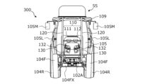
- FIG. 12 is a side view schematically showing an example of the arrangement of the fuel filling port 52.
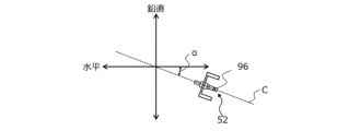
- FIG. 13 is a side view schematically showing an example of the orientation of the fuel filling port 52.
- the fuel filling port 52 connected to the fuel tank 50 by the pipe 21 is provided at a higher position than the front wheel axle 104FX.
- a fuel filling port 52 is provided at the rear portion 120C of the fixed frame 120.
- the fuel filling port 52 is preferably provided with a lid configured to open and close.
- the fuel filling port (refueling port) is provided at a position higher than the liquid fuel tank. Additionally, the distance from the liquid fuel tank to the fuel filling port is generally short. For this reason, in conventional agricultural tractors equipped with internal combustion engines, the degree of freedom in the position and orientation of the fuel filling port was low.
- the fuel hydrogen gas
- the fuel flows through the pipe 21 from the high pressure side to the low pressure side, regardless of the direction of the pipe 21. It can be easily moved towards the pressure side.
- the fuel filling port 52 can be provided at a position depending on the desired effect. Note that the pipe 21 connecting the fuel filling port 52 and the fuel tank 50 does not need to pass through the fixed frame 120.
- the fuel filling port 52 has a receptacle 96 that is inclined so that the inside is higher than the inlet. As shown in FIG. 13, the central axis C of the receptacle 96 forms an inclination angle ⁇ (0 ⁇ 90) with respect to the horizontal plane. However, at this time, the work vehicle 200 is assumed to be stationary on a horizontal road surface.
- the fuel filling port 52 can also be placed at a position higher than the elbow position of the operator who performs the fuel filling operation while standing on the ground.
- the inclination angle ⁇ shown in FIG. 13 it becomes easier to insert the dispenser nozzle 95 into the fuel filling port 52 and fill it with fuel.
- the inclination angle ⁇ may be made larger than 0 degrees. Providing such an inclination makes it difficult for foreign substances such as water to enter through the fuel filling port 52, and even if they do enter, they are likely to be discharged to the outside.
- the central axis C of the receptacle 96 forms an inclination angle ⁇ of, for example, 30 degrees or more and 90 degrees or less with respect to the horizontal plane. Further, the central axis C of the receptacle 96 may form an inclination angle ⁇ of 70 degrees or more and 90 degrees or less with respect to the horizontal plane. Depending on the position and height of the fuel filling port 52, the central axis C of the receptacle 96 may be parallel to the vertical direction. In this way, when the fuel filling port 52 faces diagonally downward or vertically downward with respect to the horizontal direction, foreign matter is difficult to enter the fuel filling port 52 and is easily discharged.
- the piping 21 has a portion extending diagonally upward or vertically upward from the connection portion with the receptacle 96. Due to the presence of such a portion, it is possible to suppress foreign matter such as water from entering deep into the interior through the fuel filling port 52.
- the basic configuration of the agricultural tractor 300 according to this embodiment is the same as the configuration of the work vehicle according to the embodiment described above.
- differences between the embodiment and the example will be explained.
- corresponding components between the embodiment and the example are given the same reference numerals.
- the agricultural tractor 300 in this embodiment includes a fixed frame 120 that is fixed to the vehicle body 102 across the driver's seat 107 and supports a fuel tank module 55 having a fuel tank 50, and a fuel cell.
- a front housing 110 that covers the module 10 is provided. Front housing 110 can be opened and closed.
- the front housing 110 includes a fixed housing part 111 fixed to the vehicle body 102 and a movable housing part 112 supported by the vehicle body 102 or the fixed housing part 111 so as to be openable and closable.
- the fixed frame 120 includes a left frame and a right frame. One end of each fixed frame 120 is fixed to the front frame 102A at a connection position 128 located in front of the front axle 104FX of the front wheel 104F. As shown in FIG. 14, in a plan view (top view) looking down from above, the front housing 110 is located between the left frame and the right frame, and protrudes ahead of the connection position 128.
- the agricultural tractor 300 of this embodiment includes a connecting bar 114 that connects the left frame and the right frame.
- the connection bar 114 in this embodiment includes a plurality of bars 114A and 114B provided at different height positions. As shown in the plan view of FIG. 16, the connection bars 114A, 114B are connected to the left and right frames 120 at positions in front of the connection position 128 of the fixed frame 120.
- the connection bar 114 has rigidity or mechanical strength to maintain a constant distance between the left and right fixed frames 120 even when an external force is applied to one or both of the left and right fixed frames 120.
- Connecting bar 114 is preferably formed from metal. The connection bar 114 contributes to increasing the overall structural strength of the fixed frame 120.
- the agricultural tractor 300 includes left and right rearview mirrors 105M and turn signals/marker lights 105L attached to the cabin 105.
- FIG. 14 shows a lead-acid battery 83 and a step 84 for getting on and off the cabin 105.
- a headlamp 130 and a work light 132 are provided on the front side of the front housing 110.
- the roof 109 is provided with a plurality of work lights, and may also be provided with various sensor devices such as a laser sensor for detecting obstacles. The locations of devices and parts included in these common agricultural tractors are not limited to the illustrated examples.
- the fuel tank module 55 is located above the cabin 105, and the left and right fixed frames 120 supporting this fuel tank module 55 are attached to the cabin. It straddles 105. Further, as shown in FIG. 18, a portion of the fixed frame 120 located behind the cabin 105 extends in the vertical direction between the left and right rear fenders 116. The rear end of each fixed frame 120 is fixed to a rear axle case (rear axle) 104RC.
- the movable housing part 112 is configured to accommodate the fuel cell module 10.
- the fixed housing part 111 accommodates a device included in the fuel cell power generation system, specifically, a radiator device 34A that radiates heat from the coolant for the fuel cell.
- the fixed frame 120 has a shape that does not interfere with the front housing 110 when the position or orientation of the front housing 110 (specifically, the movable housing portion 112) changes from the closed state to the open state.
- a connecting bar 114 that connects the left and right fixed frames 120 is arranged outside the movable range of the movable housing section 112.
- FIG. 19 is a cross-sectional view schematically showing a configuration example of the fuel filling port 52.
- FIG. 20 is a perspective view of the fuel fill port 52 in one example.
- 21 and 22 are a side view and a plan view, respectively, of an agricultural tractor 300 showing an example of the arrangement of the fuel filling port 52 in this embodiment.
- 21 and 22 schematically show preferred positions Q1 to Q6 where the fuel filling port 52 is provided.
- the fuel filling port 52 in this embodiment includes a receptacle 96, a casing 52C that accommodates the receptacle 96, and an openable and closable lid 52L.
- the lid 52L is rotatably supported by the casing 52C by a hinge member 52H.
- the receptacle 96 receives fuel supply from the dispenser nozzle 95 of the fuel filling device 90 shown in FIG. 8, as described above.
- the receptacle 96 is inserted into an opening provided at the tip of the dispenser nozzle 95 when the dispenser nozzle 95 is inserted into the fuel filling port 52 .
- the fuel injected into the receptacle 96 from the dispenser nozzle 95 in FIG. 8 is supplied to the fuel tanks 50A, 50B, and 50C through piping.
- the specific shape of the fuel filling port 52 is not limited to the example shown in FIG. 19. As shown in FIG. 20, the fuel filling port 52 in this embodiment has a lid 52L that is biased by a spring 52S, and the inner wall surface of the casing 52C may also have a complicated shape. The direction in which the receptacle 96 extends also does not need to be horizontal as described above.
- the fuel filling port 52 may be provided at an upper position Q1 or a front position Q2 of either the left or right rear fender 116. If the fuel filling port 52 is located on the rear fender 116, the rear fender 116 located between the rear wheel 104R and the fuel filling port 52 will prevent foreign objects such as mud, muddy water, soil, or sand splashed by the rear wheel 104R from becoming fuel. Adhesion to the filling port 52 is prevented. Further, the diameter of the rear wheel 104R is larger than the diameter of the front wheel 104F, and the rear fender 116 is located at a higher position than the front wheel 104F.
- the fuel filling port 52 By providing the fuel filling port 52 on the rear fender 116, the fuel filling port 52 can be placed higher than the upper end position of the front wheel 104F. This contributes to suppressing the fuel filling port 52 from getting dirty due to foreign matter such as mud thrown up by the front wheels 104F.
- the rear fender 116 has a curved surface with a relatively large area that covers the upper part of the rear wheel 104R. Therefore, it is possible to appropriately select a position suitable for connecting the pipe 21 extending from the fuel tank 50 to the fuel filling port 52 from various areas of the rear fender 116. As a result, it becomes possible to provide the fuel filling port 52 at a position suitable for shortening the length of the pipe 21 and reducing the curvature of the bent portion of the pipe 21.
- the position of the fuel filling port 52 on the rear fender 116 for example, a position higher than the upper end of the front wheel 104F and below the upper end of the rear wheel 104R can be selected.
- the height of the fuel filling port 52 from the ground may be greater than the outer diameter of the front wheel 104F and less than or equal to the outer diameter of the rear wheel 104R.
- Such a height is within the range of heights suitable for operator fuel filling.
- the fuel filling port 52 of the rear fender 116 fixed at such a height range it is easy to set the inclination angle ⁇ of the central axis C of the receptacle 96 to a range of, for example, 0 degrees or more and 70 degrees or less.
- the central axis C of such a receptacle 96 does not need to be parallel to the width direction (left-right direction) of the vehicle when viewed vertically from above, and may be inclined toward the front-rear direction of the vehicle. However, it may be parallel to the front-back direction.
- the fuel filling port 52 may be provided in a portion other than the rear fender 116.
- FIG. 22 shows a rectangular region R1 located between the left and right wheels of the front wheel 104F in a plan view vertically looking down from above. This rectangular region R1 has a width narrower than the wheel interval of the front wheels 104F. The fuel filling port 52 may be arranged within such a rectangular region R1.
- FIG. 20 also shows a rectangular region R2 located between the left and right wheels of the rear wheel 104R. This rectangular region R2 has a width narrower than the wheel interval of the rear wheels 104R.
- the fuel filling port 52 may be arranged within the rectangular region R2.
- the fuel filling port 52 may be provided, for example, at a position Q3 at the rear of the cabin 105, a position Q4 inside the cabin 105, or a position Q5 at the front. As can be seen from FIG. 20, positions Q3 and Q4 in this example are located within rectangular region R2, and position Q5 is located within rectangular region R1.
- the fuel filling port 52 When the fuel filling port 52 is provided at the rear position Q3 of the cabin 105, by removing the implement 190 from the coupling device 108, it is easy to secure a large space for the operator to perform the fuel filling operation. Particularly in the region sandwiched between the left and right rear wheels 104R, the fuel filling port 52 can be placed anywhere in a wide range in the vertical direction. For example, in a range that is sufficiently higher than the coupling device 108 (a range of 100 centimeters or more from the ground), the advantage is that even if the implement 190 is connected to the coupling device 108, fuel can be filled. There is.
- the inclination angle ⁇ of the central axis C of the receptacle 96 is set to, for example, 30 degrees or more and 90 degrees or less, preferably 70 degrees or more and 90 degrees or less. By setting the range to , fuel filling becomes easy.
- the fuel filling port 52 is provided at the rear position Q3 of the cabin 105, the fuel filling port 52 can be fixed directly or indirectly to the back surface of the cabin 105.
- the fuel filling port 52 When the fuel filling port 52 is provided at the position Q4 inside the cabin 105, it is difficult for foreign substances such as mud to enter the inside of the cabin 105 from the outside, so the fuel filling port 52 is difficult to get dirty and is easily kept clean. There are advantages.
- the fuel filling port 52 is provided at a position Q5 in front of the cabin 105, for example in the fixed housing part 111, fuel can be filled without opening the door of the cabin 105.
- the fuel filling port 52 fixed to the movable housing portion 112 is formed into a flexible tubular shape that allows the fuel filling port 52 to move as the movable housing portion 112 opens and closes. It is necessary to form at least a portion of the piping 21 using parts. A tubular part having such flexibility is not particularly required when the fuel filling port 52 is provided in the fixed housing part 111.
- the fuel filling port 52 can be provided on either the top surface or the side surface of the fixed housing part 111.
- the position of the fixed housing part 111 is not limited to the position illustrated in FIG. 19.
- the fuel filling port 52 may be arranged at a position Q6 in the internal space of the front housing 110. In this case, since the fuel filling port 52 is exposed only when the movable housing portion 112 is opened, it is possible to more effectively prevent foreign matter such as mud from adhering to the fuel filling port 52 while driving or working. becomes possible. Inside the front housing 110, the fuel filling port 52 can be provided at an appropriate position depending on the arrangement between the parts.
- the method of opening and closing the movable housing portion 112 is not limited to the example shown in FIG. 19.
- a hinge component defining the axis of rotation may be located at the front of the movable housing portion 112.
- FIG. 23 is a sectional view of the rear fender 116 showing one example of the arrangement of the fuel filling port 52 in this embodiment.
- 24A and 24B are cross-sectional views of the rear fender 116 showing still another example of the arrangement of the fuel filling port 52 in this embodiment.
- the depiction of piping for connecting the fuel filling port 52 to the fuel tank 50 is omitted.
- the fuel filling port 52 is provided at a position Q1 above the rear fender 116. Specifically, position Q1 is adjacent to the rear end of the upper surface 116T of the rear fender 116, where lamps such as the brake lamp 117 are arranged. At the rear end of the rear fender 116, external operation switches such as a three-point link operation switch and a Monroe operation switch may be arranged. Since the external operation switches are located at positions that are easy for the operator to work with, if the fuel filling port 52 is placed near them, fuel filling will also become easier.
- the receptacle 96 extends upward.
- the dispenser nozzle 95 shown in FIG. 8 is inserted downward from directly above the fuel filling port 52. Note that the direction in which the central axis of the receptacle 96 extends does not need to be parallel to the vertical direction as shown in FIG. 23.
- An opening is provided in the upper surface 116T of the rear fender 116 at a position Q1, and the casing 52C of the fuel filling port 52 is fitted into the opening. It is preferable that the surface shape of the lid 52L in the closed state of the fuel filling port 52 matches the surface shape of the upper surface 116T of the rear fender 116, but a step is formed between the lid 52L and the upper surface 116T. Good too.
- a gap of 5 centimeters or more exists between the rear fender 116 and the rear wheel 104R, and a space capable of accommodating the fuel filling port 52 and piping is formed.
- this space has a size that can accommodate the casing 52C of the fuel filling port 52.
- the distance from the rear wheel 104R to the top surface 116T of the rear fender 116 is relatively large at the top of the rear fender 116. Therefore, when the fuel filling port 52 is provided at the upper part of the rear fender 116, the effect of relatively easy handling of piping etc. can be obtained.
- the fuel filling port 52 may be provided in a portion of the upper surface 116T of the rear fender 116 other than the upper portion.
- the fuel filling port 52 is provided at a position Q2 at the front of the rear fender 116.
- the casing 52C of the fuel filling port 52 is inclined as a whole in accordance with the slope of the upper surface 116T of the rear fender 116 diagonally downward. In this case, it is easy to match the surface shape of the lid 52L with the fuel filling port 52 in the closed state to the surface shape of the upper surface 116T of the rear fender 116.
- FIG. 24A the casing 52C of the fuel filling port 52 is inclined as a whole in accordance with the slope of the upper surface 116T of the rear fender 116 diagonally downward. In this case, it is easy to match the surface shape of the lid 52L with the fuel filling port 52 in the closed state to the surface shape of the upper surface 116T of the rear fender 116.
- the orientation of the casing 52C of the fuel filling port 52 is the same as the orientation of the casing 52C in FIG. 23.
- a portion of the casing 52C is exposed from the upper surface 116T of the rear fender 116.
- a portion of the upper surface 116T of the rear fender 116 may be shaped to cover a portion or all of the casing 52C of the fuel filling port 52. From the viewpoint of protecting the fuel filling port 52, it is preferable that the portion of the fuel filling port 52 other than the lid 52L is hidden by the rear fender 116.
- the fuel filling port 52 is provided in a portion other than the upper part of the upper surface 116T of the rear fender 116, it is possible to effectively utilize the space between the rear fender 116 and the rear wheel 104R. Moreover, since such a space allows the entire fuel filling port 52 to be accommodated in various orientations, the orientation of the central axis of the receptacle 96 can be selected from a wide range.
- FIG. 25 is a sectional view showing still another example of the arrangement of the fuel filling port 52 in this embodiment.
- This sectional view is a partial sectional view when the handle stay cover (handle column case) 106X is cut along a plane that crosses the position Q4.
- the handle stay cover 106X is provided with a display 106D for displaying various information including vehicle speed, and other operating levers. Note that in FIG. 25, the steering handle (steering wheel) is not shown for ease of viewing.
- the fuel filling port 52 is provided at a position Q4 on one side (the side surface 106XL) of the side surfaces 106XL and 106XR on both sides of the handle stay cover 106X (see FIG. 21).
- An opening is provided in the side surface 106XL of the handle stay cover 106X, and the casing 52C of the fuel filling port 52 is arranged so as to close this opening.
- the central axis of the illustrated receptacle 96 is parallel to the horizontal direction (the width direction of the vehicle), but as described above, it may be inclined with respect to the horizontal direction (see FIG. 13).
- the surface shape of the lid 52L of the fuel filling port 52 in the closed state matches the surface shape of the handle stay cover 106X. However, there may be a step between the lid 52L and the handle stay cover 106X.
- the fuel filling port 52 is provided in a range where it does not get in the way of the operator going in and out of the cabin 105, and does not get in the way of steering wheel operation or switch operation.
- the fixed housing part 111 when viewed from the front from the operator seated in the driver's seat in the cabin 105, the fixed housing part 111 is arranged on the other side of the handle stay cover 106X.
- the cabin 105 has glass 105W on four sides surrounding the driver's seat.
- a glass 105W is located between the inside of the cabin 105 and the fixed housing part 111.
- the position of the steering wheel 106 is also low, making it easy for an operator standing on the ground to fill the fuel from outside the cabin 105.
- FIG. 26A is a schematic cross-sectional view of a fixed housing portion showing such a fuel fill port 52.
- 26B and 26C are a perspective view and a side view, respectively, of the fixed housing portion 111 showing an example of the arrangement of the fuel filling port 52 in this example.
- the fixed housing part 111 accommodates a component (radiator device 34A in this example) that is too large to be accommodated in the movable housing part 112.
- the fixed housing part 111 is arranged behind the movable housing part 112.
- the fixed housing part 111 in this embodiment has an upper surface part 111A, a pair of side parts 111B and 111C, and a front wall 111E.
- the front wall 111E is located on the side of the movable housing section 112 and has an opening section 111D that communicates with the inside of the movable housing section 112 in the closed state.
- a component disposed within the fixed housing portion 111 and a component disposed within the movable housing portion 112 can be connected by piping, a coolant flow path, an electric cable, or the like.
- the front wall 111E faces the rear end of the movable housing section 112 in the closed state. Therefore, the opening 111D of the fixed housing part 111 is closed by the movable housing part 112 in the closed state.
- an opening is provided at position Q5 on the side surface 111B of the fixed housing portion 111, and the lid 52L of the fuel filling port 52 is arranged to close the opening.
- the position Q5 of the fuel filling port 52 may be located on the upper surface portion 111A of the fixed housing portion 111, the other side surface portion 111C, or the front wall 111E.
- the fuel filling port 52 can be filled with fuel by bringing the movable housing portion 112 into the “open state”. In that case, the lid 52L is not essential.
- the central axis of the receptacle 96 is parallel to the horizontal direction, but the central axis of the receptacle 96 may be inclined from the horizontal direction.
- the casing 52C of the fuel filling port 52 is housed in an area where it does not interfere with various components provided inside the fixed housing portion 111.
- the casing 52C is formed between a plurality of parts housed in the fixed housing part 111, or between these parts and the upper surface part 111A, the pair of side parts 111B and 111C, and the front wall 111E of the fixed housing part 111. has a shape, size, and orientation that fits within the space provided.
- FIG. 27 is a schematic cross-sectional view of the movable housing portion 112 showing an example of the arrangement of such a fuel filling port 52.
- the fuel filling port 52 is arranged in a space surrounded by the side surfaces 112L, 112R, and the top surface 112U of the movable housing portion 112, and the lid 52L is provided at a position Q5 on the side surface 112L. It's blocking the opening.
- the surface of the lid 52L of the fuel filling port 52 may be a curved surface.
- the fuel filling port 52 may be fixed to the movable housing portion 112, or may be fixed to another component housed in the movable housing portion 112 or the front frame 102A.
- the central axis of the receptacle 96 is parallel to the horizontal direction, but the central axis of the receptacle 96 may be inclined from the horizontal direction.
- the casing 52C of the fuel filling port 52 is housed in an area where it does not interfere with various components provided inside the movable housing portion 112.
- the casing 52C has a shape that fits within a space formed between a plurality of components housed in the movable housing section 112 or between these components and the side surfaces 112L, 112R, and the top surface 112U of the movable housing section 112. , size, and orientation.
- the present disclosure includes the work vehicle described in the following items.
- the vehicle body has a left rear fender and a right rear fender that cover at least a portion of each of the rear wheels,
- the vehicle body has a left rear fender and a right rear fender that cover at least a portion of each of the rear wheels,
- the fuel cell further includes a front housing that covers the fuel cell, the front housing being supported by the front part of the vehicle body, The work vehicle according to item 6, wherein the fuel filling port is provided on the front housing.
- the fuel cell further includes a front housing that covers the fuel cell, the front housing being supported by the front part of the vehicle body, The work vehicle according to item 6, wherein the fuel filling port is arranged in an internal space of the front housing.
- the fuel filling port is located in a rectangular area located between the left and right wheels of the front wheels, and has a width narrower than a wheel interval of the front wheels.
- the fuel filling port is located in a rectangular area located between the left and right wheels of the rear wheels, and has a width narrower than the distance between the rear wheels.
- the vehicle body has a left rear fender and a right rear fender that cover at least a portion of each of the rear wheels,
- the work vehicle according to any one of items 15 to 19, wherein the fuel filling port is provided on either the left rear fender or the right rear fender.
- the vehicle body has a left rear fender and a right rear fender that cover at least a portion of each of the rear wheels,
- the work vehicle according to any one of items 15 to 19, wherein the fuel filling port is located between the left rear fender and the right rear fender.
- a front housing accommodating the fuel cell, the front housing being supported by the front part of the vehicle body; 26.
- a front housing accommodating the fuel cell, the front housing being supported by the front part of the vehicle body; 26.
- the technology of the present disclosure can be applied to, for example, work vehicles such as agricultural tractors, riding management machines, and vegetable transplanters.
- SYMBOLS 10 Fuel cell module, 11... FC stack, 40... Boost circuit, 34... Radiator device, 40... Boost circuit, 50... Fuel tank, 51... Tank case, 70... Motor, 71... Output shaft, 72... Inverter device, 74... Power transmission system, 76... Power take-off (PTO) shaft, 80... Battery pack, 81... First DC-DC converter, 82... Second DC-DC converter, 83... Storage battery, 85... Cooling compressor, 86... Heater, 100...
Landscapes
- Engineering & Computer Science (AREA)
- Life Sciences & Earth Sciences (AREA)
- Sustainable Development (AREA)
- Sustainable Energy (AREA)
- Transportation (AREA)
- Mechanical Engineering (AREA)
- Chemical & Material Sciences (AREA)
- Combustion & Propulsion (AREA)
- Power Engineering (AREA)
- Arrangement Or Mounting Of Propulsion Units For Vehicles (AREA)
- Electric Propulsion And Braking For Vehicles (AREA)
- Fuel Cell (AREA)
Abstract
本発明の作業車両は、燃料電池と、燃料電池に供給する燃料を収容する少なくとも1つの燃料タンクと、燃料電池に接続されるモータと、前輪および後輪を回転可能に支持する車体と、燃料タンクに配管によって接続されている燃料充填口とを備える。燃料充填口は、前輪の車軸よりも高い位置に設けられている。
Description
本開示は、電動モータおよび燃料電池を備える作業車両に関する。
「人」または「物」を移動させることが主目的の自動車の分野では、走行のための駆動力(トラクション)を、内燃機関に代えて電動モータ(以下、「モータ」と称する。)によって発生させる電気自動車(EV)が普及しつつある。
一方、脱炭素化社会を実現するため、圃場で使用されるトラクタなどの作業車両が排出する二酸化炭素(CO2)の量を低減することも求められている。一般的な自動車とは異なり、トラクタなどの作業車両では、インプルメントと呼ばれる作業機を牽引して耕耘などの農作業をさせる必要がある。このため、作業車両の電動化を実現するには、乗用車の電動化とは異なる解決すべき課題がある。
特許文献1は、従来のエンジン駆動式のトラクタの構造を大幅に変更しないで燃料電池(Fuel Cell: FC)発電システムとモータとを備えるトラクタを開示している。
燃料電池によって作業車両の発電システムを実現するには、燃料を蓄える燃料タンクだけではなく、種々の部品が必要である。しかし、作業車両は、一般的な自動車とは異なり、例えばインプルメントを牽引したり、持ち上げたり、回転させたりするための機械的構造を備えている。このため、作業車両には、従来の電気自動車における燃料電池発電システムの構成をそのまま採用することができない、という課題がある。
本開示は、このような課題を解決することができる作業車両を提供する。
本開示による作業車両は、例示的で非限定的な実施形態において、燃料電池と、前記燃料電池に供給する燃料を収容する少なくとも1つの燃料タンクと、前記燃料電池に接続されるモータと、前記燃料電池、前記燃料タンク、および前記モータを支持する車体であって、前輪および後輪を回転可能に支持する車体と、前記燃料タンクに配管によって接続されている燃料充填口とを備える。前記燃料充填口は、前記前輪の車軸よりも高い位置に設けられている。
本開示による作業車両は、例示的で非限定的な実施形態において、燃料電池と、前記燃料電池に供給する燃料を収容する少なくとも1つの燃料タンクと、前記燃料電池に接続されるモータと、前記燃料電池、前記燃料タンク、および前記モータを支持する車体であって、前輪および後輪を回転可能に支持する車体と、前記燃料タンクに配管によって接続されている燃料充填口とを備える。前記燃料充填口は、入口よりも内部で高くなるように傾斜したレセプタクルを有する。
本開示の実施形態によれば、燃料充填口に泥水または土などの異物が付くことを抑制して、燃料充填口周辺の清浄度を高めることが可能になる。本開示の他の実施形態によれば、燃料充填口からレセプタクルの内部に水などの異物が侵入しても外部に排出されやすく、異物が配管の内部奥深くに侵入していくことを抑制することが可能になる。
以下、本開示の実施形態を説明する。ただし、必要以上に詳細な説明は省略する場合がある。例えば、既によく知られた事項の詳細説明および実質的に同一の構成に関する重複する説明を省略する場合がある。これは、以下の説明が不必要に冗長になることを避け、当業者の理解を容易にするためである。なお、発明者は、当業者が本開示を十分に理解するために添付図面および以下の説明を提供するのであって、これらによって特許請求の範囲に記載の主題を限定することを意図していない。以下の説明において、同一または類似の機能を有する構成要素については、同じ参照符号を付している。
下記の実施形態は例示であり、本開示の技術は、以下の実施形態に限定されない。例えば、以下の実施形態について示される数値、形状、材料、ステップ、そのステップの順序、表示画面のレイアウトなどは、あくまでも一例であり、技術的に矛盾が生じない限りにおいて種々の改変が可能である。また、技術的に矛盾が生じない限りにおいて、一の態様と他の態様とを組み合わせることが可能である。
本開示における「作業車両」は、作業地で作業を行うために使用される車両(ビークル)を意味する。「作業地」は、例えば圃場、山林、または建設現場等の、作業が行われる任意の場所である。「圃場」は、例えば果樹園、畑、水田、穀物農場、または牧草地等の、農作業が行われる任意の場所である。作業車両は、例えばトラクタ、田植機、コンバイン、乗用管理機、もしくは乗用草刈機などの農業機械、または、建設作業車もしくは除雪車などの、農業以外の用途で使用される車両であり得る。本開示における作業車両は、その前部および後部の少なくとも一方に、作業内容に応じたインプルメント(「作業機」または「作業装置」とも呼ばれる。)を装着することができる。作業車両が作業を行いながら走行することを「作業走行」と称することがある。
なお、「農業機械」は、農業用途で使用される機械を意味する。農業機械の例は、トラクタ、収穫機、田植機、乗用管理機、野菜移植機、草刈機、播種機、施肥機、および農業用移動ロボットを含む。トラクタのような作業車両が単独で「農業機械」として機能する場合だけでなく、作業車両に装着または牽引されるインプルメントと作業車両の全体が一つの「農業機械」として機能する場合がある。農業機械は、圃場内の地面に対して、耕耘、播種、防除、施肥、作物の植え付け、または収穫などの農作業を行う。
1.<作業車両の基本構成>
本開示における作業車両の実施形態を具体的に説明する前に、本開示における作業車両の基本構成と動作の例を説明する。以下に説明する作業車両は、モータと、モータの駆動に必要な発電を行う燃料電池発電システム(以下、「FC発電システム」と称する。)を搭載している。
本開示における作業車両の実施形態を具体的に説明する前に、本開示における作業車両の基本構成と動作の例を説明する。以下に説明する作業車両は、モータと、モータの駆動に必要な発電を行う燃料電池発電システム(以下、「FC発電システム」と称する。)を搭載している。
図1は、本開示における作業車両100の基本構成の例を模式的に示す平面図である。本開示において、作業車両100がまっすぐ前に走行するときの進行方向を「前方向」、まっすぐ後ろに走行するときの進行方向を「後方向」と呼ぶことにする。地面に平行な平面内において、「前方向」に対して垂直に右へ延びる方向を「右方向」、垂直に左へ延びる方向を「左方向」と呼ぶ。図1では、「前方向」、「後方向」、「右方向」、および「左方向」を、それぞれ、「前」、「後」、「右」、および「左」の矢印によって示している。前方向および後方向の両方を総称して「前後方向」、右方向および左方向の両方を総称して「幅方向」と呼ぶ場合がある。
図示されている例における作業車両100は、例えば、農業機械の一例であるトラクタである。本開示の技術は、トラクタなどの作業車両に限られず、他の種類の作業車両にも適用することができる。作業車両100は、インプルメントを装着または牽引し、インプルメントの種類に応じた農作業を行いながら圃場内を走行することができる。また、作業車両100は、インプルメントを持ち上げた状態、または装着しない状態で、圃場内および圃場外(道路を含む)を走行することもできる。
作業車両100は、従来のトラクタと同様に、左右の前輪104Fおよび左右の後輪104Rを回転可能に支持する車体(車両フレーム)102を備えている。車体102は、前輪104Fが設けられるフロントフレーム102Aと、後輪104Rが設けられる伝動ケース102Bとを含む。フロントフレーム102Aは、伝動ケース102Bの前部に固定されている。前輪104Fおよび後輪104Rを総称して車輪104と称する場合がある。厳密には、車輪104は、ホイールであり、タイヤが装着されている。本開示において「車輪」は、原則として、「ホイールおよびタイヤ」の全体を意味する。前輪104Fおよび後輪104Rの一方、または両方は、タイヤ付き車輪ではなく無限軌道(track)を装着した複数の車輪(クローラ)に置き換えられてもよい。
図1の例における作業車両100は、フロントフレーム102Aによって直接または間接的に支持される燃料電池モジュール(FCモジュール)10およびモータ70を備えている。FCモジュール10は、燃料電池スタック(FCスタック)を有しており、後述するように、燃料から電力を発生させる車載発電機として機能する。以下、「FCモジュール」または「FCスタック」を、単に「燃料電池」と称する場合がある。
モータ70は、FCモジュール10に電気的に接続される。モータ70は、FCモジュール10で発生する電力を機械的運動(動力)に変換して、作業車両100の走行に必要な駆動力(トラクション)を発生させることができる。モータ70の例は、交流同期モータである。FCモジュール10のFCスタックは直流電流を生成するため、モータ70が交流同期モータである場合、FCスタックとモータ70との間には、インバータ装置を含む電気回路群が設けられ、直流電流が交流電流に変換される。このような電気回路群の一部は、FCモジュール10の内部にあってもよい。また、電気回路群の他の一部は、モータ70の駆動回路としてモータ70に取り付けられていてもよい。
モータ70は、回転する出力軸71を有している。出力軸71のトルクは、伝動ケース102Bの内部に設けられたトランスミッション(変速装置)、および後輪差動装置(デファレンシャルギア装置)などの機械部品を介して後輪104Rに伝達される。言い換えると、動力源であるモータ70が生み出す動力は、伝動ケース102B内に設けられたトランスミッションを含む動力伝達系(ドライブトレイン)74によって後輪104Rに伝えられる。このため、「伝動ケース」を「ミッションケース」と呼んでもよい。なお、四輪駆動モードでは、モータ70の動力の一部が前輪104Fにも伝達される。モータ70の動力は、作業車両100の走行だけではなく、インプルメントの駆動にも利用され得る。具体的には、伝動ケース102Bの後端にパワーテイクオフ(PTO)軸76が設けられており、モータ70の出力軸71のトルクがPTO軸76に伝達される。作業車両100に装着または牽引されるインプルメントは、PTO軸76から動力を受け取り、種々の作業に応じた動作を実行することができる。モータ70および動力伝達系74を総称して電動パワートレインと呼んでもよい。伝動ケース102B内の変速装置の例は、国際公開公報第2022/038860号に開示されているので、その内容の全体をここに援用する。
このように、本開示による作業車両100には、ディーゼルエンジンなどの内燃機関が搭載されておらず、FCモジュール10およびモータ70が搭載されている。また、モータ70の出力軸71は、伝動ケース102B内のトランスミッション等の動力伝達系74に機械的に結合されている。モータ70は、内燃機関に比べて相対的に広い回転速度範囲において効率的にトルクを発生することができる。しかし、トランスミッションを含む動力伝達系74を利用することにより、多段または無段の変速動作を実行して、モータ70からのトルクおよび回転速度を更に広い範囲で調整することが容易になる。このため、作業車両100の走行だけではなく、インプルメントを用いた多様な作業を効率的に実行することが可能になる。
なお、作業車両100の用途またはサイズに応じて、動力伝達系74の一部の機能が削除されてもよい。例えば、変速機能を担うトランスミッションの一部または全部が省略されてもよい。モータ70の個数および搭載位置も、図1に示される例に限定されない。
作業車両100は、FCモジュール10に供給する燃料を収容する少なくとも1つの燃料タンク50を備えている。図1では、簡単のため、1個の燃料タンク50が記載されている。ある実施形態では、複数の燃料タンク50がタンクケースに収容され、燃料タンクモジュールを構成する。燃料タンク50は、後述するように、車体102に固定された部材によって支持される。FCモジュール10および燃料タンク50は配管および開閉弁などによって連結され、車載のFC発電システムを形成する。FC発電システムの構成と動作については後述する。
後述する実施形態における作業車両100は、車体102によって支持される運転席を備えている。運転席は、車体102に支持されるキャビンによって囲まれ得る。後述する実施形態において、FCモジュール10は運転席の前方に配置され、燃料タンク50は運転席の上方に配置される。このようなFCモジュール10および燃料タンク50は、少なくとも1つの「収容体」に収容される。「収容体」は、例えばハウジングとして機能し、FCモジュール10および燃料タンク50を太陽光の照射および風雨から保護する役割を果たす。また、このような収容体は、FCモジュール10または燃料タンク50から燃料ガスが漏れた場合、燃料ガスの大気中への拡がりを制御して燃料ガスの検知を容易にすることもできる。
FCモジュール10は、例えば、「ボンネット」と呼ばれるフロントハウジングに収容され得る。フロントハウジングは、「収容体」の一部である。フロントハウジングは、車体102の前部(フロントフレーム102A)によって支持される。燃料タンク50は、前述したようにタンクケースに収容され得る。タンクケースは、車体102によって直接または間接的に支持される。
2.<FC発電システム>
次に、図2を参照して、作業車両100に搭載されるFC発電システム180の基本的な構成例を説明する。
次に、図2を参照して、作業車両100に搭載されるFC発電システム180の基本的な構成例を説明する。
図2に示されるFC発電システム180は、図1の作業車両100における車載発電システムとして機能する。FC発電システム180の発電によって生じた電力は、作業車両100の走行だけではなく、作業車両100が牽引または装着するインプルメントの動作にも用いられる。
図示される例におけるFC発電システム180は、FCモジュール10と、FCモジュール10に供給する燃料を収容する少なくとも1つの燃料タンク50とを含む。また、FC発電システム180は、FCモジュール10を冷却するためのラジエータ装置34を備えている。
FCモジュール10は、主な構成部品として、燃料電池スタック(FCスタック)11と、空気(エア)コンプレッサ12と、燃料循環ポンプ24と、冷却液ポンプ31と、昇圧回路40と、制御装置42とを備えている。これらの構成部品は、FCモジュール10の筐体内に収容され、電気的または流体的連通によって互いに接続されている。
FCスタック11は、燃料である「アノードガス」と、酸化ガスである「カソードガス」との電気化学反応によって発電を行う。この例におけるFCスタック11は、固体高分子形燃料電池である。FCスタック11は、複数の単セルが積層されたスタック構造を有している。単セルは、例えばイオン交換膜から形成された電解質膜と、電解質膜の一方の面に形成されたアノード極と、電解質膜の他方の面に形成されたカソード極と、アノード極およびカソード極を両側から挟む一対のセパレータとを備えている。単セルで生じる電圧は、例えば1ボルト以下である。このため、FCスタック11では、数百ボルトの電圧を生成するように例えば300個以上の単セルが直列に接続されている。
FCスタック11のアノード極には、アノードガスが供給される。アノードガスは、「燃料ガス」、または、単に「燃料」と呼ばれる。本開示の実施形態において、アノードガス(燃料)は、水素ガスである。カソード極にはカソードガスが供給される。カソードガスは、空気などの酸化ガスである。アノード極は燃料極と呼ばれ、カソード極は空気極と呼ばれる。
アノード極では、下記の式(1)に示される電気化学反応が生じる。
2H2→4H++4e- ・・・式(1)
2H2→4H++4e- ・・・式(1)
カソード極では、下記の式(2)に示される電気化学反応が生じる。
4H++4e-+O2→2H2O ・・・式(2)
4H++4e-+O2→2H2O ・・・式(2)
全体として、下記の式(3)の反応が生じる。
2H2+O2→2H2O ・・・式(3)
2H2+O2→2H2O ・・・式(3)
上記の反応に用いられた後のアノードガスは「アノードオフガス」と称され、反応に用いられた後のカソードガスは「カソードオフガス」と称される。
空気コンプレッサ12は、外部から取り入れた空気をカソードガスとしてFCスタック11のカソード極に供給する。空気コンプレッサ12を含むカソードガス供給系は、カソードガス供給管13、カソードオフガス管14、およびバイパス管15を有している。カソードガス供給管13は、空気コンプレッサ12から供給されるカソードガス(空気)をFCスタック11のカソード極に流す。カソードオフガス管14は、FCスタック11から排出されるカソードオフガスを外気へ流す。バイパス管15は、空気コンプレッサ12の下流におけるカソードガス供給管13から分岐し、FCスタック11を迂回してカソードオフガス管14に接続される。バイパス管15には、バイパス管15に流れるカソードガスの流量を調整する制御弁16が設けられている。カソードガス供給管13には、FCスタック11へのカソードガスの流入を選択的に遮断する遮断弁17が設けられている。カソードオフガス管14には、カソードガスの背圧を調整する調圧弁18が設けられている。
FCモジュール10のカソードガス供給系には、空気コンプレッサ12の回転数を検出する回転数検出センサS1と、カソードガス供給管13に流れるカソードガスの流量を検出するガス流量検出センサS2とが設けられている。制御弁16、遮断弁17、および調圧弁18は、例えば電磁弁である。
燃料循環ポンプ24は、燃料タンク50から送られてきた燃料ガス(アノードガス)をFCスタック11のアノード極に供給する。燃料循環ポンプ24を含むアノードガス供給系は、アノードガス供給管21、アノードオフガス管22、および循環流路23を有する。アノードガス供給管21は、燃料タンク50から供給されるアノードガスをFCスタック11のアノード極に流す。本開示の実施形態における燃料タンク50は、高圧水素ガスを貯蔵する水素タンクである。
アノードオフガス管22は、FCスタック11から排出されるアノードオフガスを流す。アノードオフガスは、アノードオフガス管22を通じて気液分離装置25に導かれて水分が除去される。水分が除去されたアノードオフガスは、燃料循環ポンプ24によって循環流路23を通じてアノードガス供給管21に戻される。循環流路23を循環するアノードオフガスは、排気弁26の開弁により、アノードオフガス管22を通じて排出され得る。気液分離装置25に貯留する水分は、排気弁26の開弁により、アノードオフガス管22を通じて排出され得る。排気弁26は、例えば電磁弁である。図の例において、アノードオフガス管22は、カソードオフガス管14に接続されている。このような構成を採用することにより、電気化学反応に寄与しなかった未反応のアノードガスを含むアノードオフガスを循環させ、再びFCスタック11に供給することにより、アノードガスの利用効率を向上させることが可能である。
FCスタック11の能力を高めるには、その温度制御が重要である。水素ガスと酸素ガスとから水を生成する反応を通じて電気を生み出すとき、熱も発生するため、冷却が必要になる。図2には、FCスタック11のための冷却液ポンプ31を含む冷却液循環系が記載されているが、後述するように、他の電装品のための冷却循環系も設けられ得る。なお、FCモジュール10が備える空気コンプレッサ12、燃料循環ポンプ24、および冷却液ポンプ31は、それぞれが内蔵するモータによって動作する。これらのモータも電装品である。
図2の冷却液ポンプ31を含む冷却液循環系は、冷却液供給管32と、冷却液排出管33と、ラジエータ装置34と、温度センサS3とを有する。この冷却液循環系は、FCスタック11を介して冷却液を循環させることによって、FCスタック11の温度を所定の範囲内に調整することができる。冷却液は、冷却液供給管32を通じてFCスタック11に供給される。供給された冷却液は、単セル間に形成された冷却液流路を流れ、冷却液排出管33へと排出される。冷却液排出管33へ排出された冷却液は、ラジエータ装置34へと流れる。ラジエータ装置34は流入した冷却液と外気とを熱交換させることにより冷却液の放熱を行い、温度が低下した冷却液を冷却液供給管32へと再び供給する。
冷却液ポンプ31は、FCスタック11に冷却液を送り出すように、冷却液供給管32または冷却液排出管33に設けられる。冷却液排出管33と冷却液供給管32との間には、冷却液のバイパス流路が設けられ得る。その場合、冷却液排出管33から冷却液バイパス流路が分岐する分岐点には分流弁が設けられる。分流弁は、バイパス流路に流れる冷却液の流量を調整することができる。温度センサS3は、冷却液排出管33を流れる冷却液の温度を検出する。
FCスタック11を冷却するために用いられる冷却液は、冷却液用の電動ポンプ(冷却液ポンプ)31によって流路を循環する。FCスタック11の下流には冷却液制御バルブが設けられ得る。冷却液制御バルブは、ラジエータ装置34に流れる冷却液とラジエータ装置34をバイパスする冷却液の比率を調整し、冷却液の温度をより高い正確度で制御することを可能にする。更に、冷却液ポンプによる送水量を制御することにより、FCスタック11の入口および出口の冷却液温度差を所望の範囲内に収まるように制御することも可能である。FCスタック11における冷却液の温度は、FCスタック11の発電効率が高い温度、例えば70℃程度になるよう制御され得る。
FCスタック11を流れる冷却液は、通常の電装品を冷却するために用いられる冷却液に比べて、より高い絶縁性を有することが好ましい。FCスタック11には、例えば300ボルトを超える高い電圧が生じるため、冷却液の電気抵抗を高めることにより、冷却液またはラジエータ装置34などを介して電流リークが生じることを抑制できる。冷却液の使用が進むにつれて冷却液の電気抵抗が低下する場合がある。FCスタック11を流れる冷却液にイオンが溶け込むためである。このようなイオンを冷却液から除去して絶縁性を高めるため、冷却液の流路にはイオン交換器が配置されていることが望ましい。
昇圧回路40は、FCスタック11から発電動作によって出力される電圧を所望のレベルに上昇させることができる。昇圧回路40の後段は、モータ駆動のためのインバータ装置を含む強電系の電気回路に接続される。なお、後述するように、昇圧回路40の後段は、降圧回路を介して弱電系の電気回路にも並列的に接続され得る。
制御装置42は、FCモジュール10による発電を制御する電子制御ユニット(ECU)である。制御装置42は、各種センサ類から出力される信号に基づいてFC発電システム180の運転状態を検出または推定する。制御装置42は、FC発電システム180の運転状態、および、上位のコンピュータまたは他のECUから出力される指令に基づいて、空気コンプレッサ12、燃料循環ポンプ24、冷却液ポンプ31、および各種弁の動作を制御して、FCスタック11による発電を制御する。制御装置42は、例えば、プロセッサ、記憶装置、および入出力インタフェースを備える。
以下の説明においては、簡単のため、「アノードガス」を「燃料ガス」または「燃料」と称し、「アノードガス供給管」を「配管」と称する。
3.<作業車両のシステム構成例>
次に図3および図4を参照しながら、作業車両100のシステム構成の例を説明する。図3は、本開示による作業車両100の構成部品間の電気的接続および動力伝達の例を模式的に示すブロック図である。図4は、図3の構成例よりも詳細な構成を示すブロック図である。図4には、作業車両100における構成部品間の電気信号の経路(細実線)および冷却液の経路(点線)が模式的に示されている。
次に図3および図4を参照しながら、作業車両100のシステム構成の例を説明する。図3は、本開示による作業車両100の構成部品間の電気的接続および動力伝達の例を模式的に示すブロック図である。図4は、図3の構成例よりも詳細な構成を示すブロック図である。図4には、作業車両100における構成部品間の電気信号の経路(細実線)および冷却液の経路(点線)が模式的に示されている。
まず、図3を参照して、構成部品の電気的接続および動力伝達の例を説明する。電気的接続は、強電系および弱電系の両方を含む。強電系の電気的接続は、例えばインバータ装置の電源電圧を提供する。弱電系の電気的接続は、例えば、比較的低い電圧で動作する電子部品の電源電圧を提供する。
図3に示される例において、作業車両100は、FCモジュール10、インバータ装置72、モータ70、動力伝達系74、およびPTO軸76を備えている。FCモジュール10のFCスタック11で発生した電力の直流電圧は、昇圧回路40によって昇圧された後、インバータ装置72に供給される。インバータ装置72は、直流電圧を例えば三相交流電圧に変換してモータ70に与える。インバータ装置72は、複数のパワートランジスタを含むブリッジ回路を有している。モータ70は、回転するロータと、インバータ装置72に電気的に接続される複数のコイルを有するステータとを有する。ロータは、例えばリダクションギア(減速機)を介して、あるいは直接に出力軸71に結合している。モータ70は、インバータ装置72からの三相交流電圧の波形に応じて制御されたトルクおよび回転速度で出力軸71を回転させる。
モータ70の出力軸71のトルクは、動力伝達系74に伝えられる。動力伝達系74は、モータ70を動力源として動作し、図1の車輪104R、104F、および/または、PTO軸76を駆動することができる。このような動力伝達系74は、ディーゼルエンジンなどの内燃機関を備える従来のトラクタにおける動力伝達系と同様の構造または類似の構造を有し得る。例えば農業トラクタなどに用いられている動力伝達系を採用することにより、FC発電システムを搭載した農業用途の作業車両100を製造するための設計コストおよび製造コストを抑えることが可能になる。動力伝達系74は、モータ70からの動力をクラッチ、トランスミッション、および後輪差動装置等を介して左右の後輪104Rに伝達する走行系動力伝達機構と、モータ70からの動力をPTO軸76に伝達するPTO系動力伝達機構とを含む。図1の伝動ケース102Bは、クラッチおよびトランスミッション等を収納した前部ケース(ミッションケース)と、後輪差動装置等を収容した後部ケース(デファレンシャルギアケース)とに分割されていてもよい。後部ケースは、後車軸ケースとも呼ばれる。
作業車両100は、FCモジュール10による発電で生まれた電気エネルギを一時的に蓄える二次電池(バッテリパック)80を備えている。バッテリパック80の例は、リチウムイオン電池のパックを含む。バッテリパック80は、FCモジュール10と協働して、あるいは単独で、インバータ装置72に必要なタイミングで電力を供給することができる。バッテリパック80としては、乗用電気自動車で利用されている種々のバッテリパックを採用することが可能である。
作業車両100は、モータ70およびインバータ装置72以外にも、電気によって動作する各種の電装品(車載電子部品)を備えている。電装品の例は、開閉弁20などの電磁バルブ、ラジエータ装置34の空冷ファン、冷房用コンプレッサ85の電動ポンプ、FCスタック11を加熱または冷却する温度制御装置を含む。このような温度制御装置は、電気ヒータ86を含む。また、これらの電装品の動作に適した電源電圧を得るためのDC-DCコンバータ81、82、蓄電池83も、電装品に含まれ得る。更には、図示されていない様々な電子部品(ランプ、油圧系の電動モータなど)も電装品に含まれ得る。これらの電装品は、例えば、従来の農業トラクタに備え付けられていた電装品と同様の電子部品であり得る。
図3の例において、第1のDC-DCコンバータ81は、FCモジュール10の昇圧回路40から出力される電圧を、第1電圧、例えば12ボルトに降圧する回路である。蓄電池83は、例えば鉛蓄電池であり、第1のDC-DCコンバータ81から出力される電圧で電気エネルギを蓄えることができる。蓄電池83は、例えばランプなどの各種電装品の電源として利用され得る。
図3に示す作業車両100は、FCモジュール10が出力する高い電圧を降圧する電圧変換回路として、第1のDC-DCコンバータ81だけではなく、第2のDC-DCコンバータ82を備えている。第2のDC-DCコンバータ82は、FCモジュール10の昇圧回路40から出力される電圧(例えば数百ボルト)を、第1電圧よりも高い第2電圧、例えば24ボルトに降圧する回路である。ラジエータ装置34の空冷ファンは、例えば、第2のDC-DCコンバータ82から出力される電圧で動作することができる。なお、ラジエータ装置34は、図3において、単一の部品として記載されているが、一台の作業車両100が複数のラジエータ装置34を備えていてもよい。また、冷房用コンプレッサ85の電動ポンプ、および電気ヒータ86も、第2のDC-DCコンバータ82から出力される電圧で動作することができる。
図3に示す作業車両100は、FC発電システムに含まれるFCスタック11を冷却または加熱する温度制御装置を備えている。このような温度制御装置の動作には比較的大きな電力が必要である。第2のDC-DCコンバータ82が出力する相対的に高い24ボルトの電圧は、このような温度制御装置に与えられる。本実施形態における温度制御装置は、FCスタック11を冷却する冷媒の放熱を行うラジエータ装置34を含み、第2のDC-DCコンバータ82が出力する相対的に高い24ボルトの電圧第2電圧は、ラジエータ装置34に与えられる。温度制御装置は、FCスタック11を加熱するヒータ86を含む。第2のDC-DCコンバータ82が出力する相対的に高い電圧は、ヒータにも与えられてもよい。第2のDC-DCコンバータ82が出力する相対的に高い電圧は、例えば冷房用コンプレッサ85のような空調装置にも与えられてもよい。
なお、作業車両100は、FCモジュール10が出力する高い電圧を、第2電圧よりも高い第3電圧に変換する第3の電圧変換回路を備えていてもよい。第3電圧は例えば48ボルトである。作業車両100がモータ70とは別に他のモータを備える場合、例えば第3電圧をそのような他のモータの電源として利用してもよい。
燃料電池発電システムを搭載する農業用作業車両では、農作業に必要な電装品以外に、燃料電池発電の動作に必要な電装品を備えるため、それぞれの電装品に適した電圧の大きさが異なり得る。本開示の実施形態によれば、適切な大きさの電圧を供給することが可能になる。
図3の例において、複数の燃料タンク50が1個のタンクケース51内に収容されている。燃料タンク50は、外部から燃料が充填される充填口(燃料充填口)52に接続されている。この接続は、燃料ガスを流すための配管21によって行われる。また、燃料タンク50は、開閉弁20が設けられた配管21を介してFCモジュール10に接続される。燃料ガスとして水素が用いられる場合、これらの配管21は、水素脆化に対する耐性が高い材料、例えばSUS316Lなどのオーステナイト系ステンレス鋼から形成され得る。
後述するように、タンクケース51には、バルブスペース53が設けられており、このバルブスペース53の中に、減圧バルブを含む種々のバルブが配置される。バルブスペース53に設けられた各種のバルブを介して、配管21は燃料タンク50とFCモジュール10とを接続する。タンクケース51とFCモジュール10とを接続する配管21には、減圧バルブによって圧力が低下した燃料ガスが流れる。燃料ガスが水素ガスである場合、燃料タンク50には、例えば35メガパスカル以上の高圧水素ガスが充填され得るが、減圧バルブを通過した後の水素ガスは、例えば2気圧程度またはそれ以下に減圧され得る。
次に図4を参照する。図4には、図3の記載に加えて、作業車両100内で通信を行う複数のECUと、ユーザインタフェース1とが記載されている。通信は、電気信号の経路(細実線)として機能するCANバス配線などを介して実行され得る。図4には、また、構成部品のサーマルマネージメントを実現するための冷却システムも記載されている。具体的には、冷却液の経路(点線)が模式的に示されている。
なお、前述したように、第1および第2のDC-DCコンバータ81、82は、それぞれ、異なる大きさの電圧を出力することができる。これらの第1および第2のDC-DCコンバータ81、82にも、それぞれの電圧変換回路を制御するECUが設けられる。これらのECUには、他のECUと同様に、第1のDC-DCコンバータ81が出力する相対的に低い第1電圧が与えられる。
図4の例において、作業車両100は、冷却液ポンプ31A、31Bによって冷却液が循環する冷却システムを備えている。これらの冷却液ポンプ31A、31Bは、FCモジュール10の内部に設けられている。この例における冷却システムは、FCスタック11の冷却を担う第1のラジエータ装置34Aと、他の電装品の冷却を担う第2のラジエータ装置34Bとを含んでいる。冷却システムは、FCスタック11と第1のラジエータ装置34Aとの間を冷却液が流れる流路(第1流路)を有している。また、この冷却システムは、モータ70を含む電装品と第2のラジエータ装置34Bとの間を冷却液が流れる流路(第2流路)を有している。なお、図4の例では、例えば、キャビンの暖房に利用されるヒータコア87が設けられており、第1のラジエータ装置34Aを流れる冷却液は、このヒータコア87を流れる。
ユーザインタフェース1は、アクセルペダル(またはアクセルレバー)などの操作装置2と、操作装置2に接続されるメインECU3とを有している。メインECU3は、メインメータ4に接続される。メインメータ4は、作業車両100の走行状態または動作状態を特定する各種パラメータを表示することができる。ユーザインタフェース1は、FC発電システムを制御するためのFCシステムECU5を更に備えている。FCシステムECU5は、FCメータ6に接続される。FCメータ6は、FC発電システムの動作状態を特定する各種パラメータを表示することができる。
バッテリパック80のセルは、バッテリマネージメントユニット(BMU)によって制御される。BMUは、バッテリのセルごとの電圧モニタ、過充電・過放電の監視、セルバランス制御を行う回路およびCPU(Central Processing Unit)を備えている。これらの回路およびCPUは、バッテリコントローラ基板に搭載され得る。
4.<実施形態>
次に、図5から図7を参照して、本開示による作業車両の実施形態について基本的な構成を説明する。図5は、本実施形態における作業車両200の構成例を模式的に示す側面図である。図6Aは、作業車両200における主要部の配置関係の例を模式的に示す側面図であり、図6Bは、その平面図である。図7は、燃料タンク50を支持する機構を模式的に示す図である。
次に、図5から図7を参照して、本開示による作業車両の実施形態について基本的な構成を説明する。図5は、本実施形態における作業車両200の構成例を模式的に示す側面図である。図6Aは、作業車両200における主要部の配置関係の例を模式的に示す側面図であり、図6Bは、その平面図である。図7は、燃料タンク50を支持する機構を模式的に示す図である。
4.1.固定フレーム
本実施形態における作業車両200は、FCモジュール10、燃料タンク50、モータ70、運転席107、および車体102を備えている。作業車両200は、図1を参照しながら説明した作業車両100における構成と同様の構成を備えている。
本実施形態における作業車両200は、FCモジュール10、燃料タンク50、モータ70、運転席107、および車体102を備えている。作業車両200は、図1を参照しながら説明した作業車両100における構成と同様の構成を備えている。
本実施形態では、燃料タンク50が、固定フレーム120によって支持されている。固定フレーム120は、運転席107を跨いで車体102に固定されている。本実施形態における作業車両200では、固定フレーム120が備える構成および機能により、燃料タンク50を運転席107の上方において安定して支持することが可能になる。その結果、車体102が支持するFCモジュール10、モータ70などの部品配置の自由度が高まる。また、従来のエンジン駆動式のトラクタの構造を大幅に変更する必要性も低下する。これらのことは、設計コストおよび製造コストの低下に寄与する。
以下、固定フレーム120の構成例を説明する。
本実施形態において、固定フレーム120は、車体102に固定されるパイプなどの長軸状の構造物である。固定フレーム120は、図6Aに示されるように、前部120Aと、中間部120Bと、後部120Cとを有している。前部120Aは、湾曲した形状を有し、中間部120Bにつながっている。中間部120Bは、前後方向に直線状に延びる形状を有し、後部120Cにつながっている。後部120Cは、鉛直方向に直線状に延びる形状を有している。なお、図示される固定フレーム120の形状は一例にすぎず、固定フレーム120の形状は、この例に限定されない。
本実施形態において、車体102は、前輪104Fを回転可能に支持するフロントフレーム102Aと、後輪104Rを回転可能に支持する伝動ケース102Bとを有している。図6Aに示されるように、固定フレーム120の一端(前端)128は、フロントフレーム102Aに固定される。固定フレーム120の他端(後端)129は、伝動ケース102Bに固定される。これらの固定は、固定フレーム120の材料に応じて、溶接またはボルト接合など適切な方法によって行われ得る。固定フレーム120は、例えば金属、合成樹脂、炭素繊維、または、炭素繊維強化プラスチックもしくはガラス繊維強化プラスチックなどの複合材料から形成され得る。伝動ケース102Bは、後車軸ケースを含み、固定フレーム120の後端129は、後車軸ケースに固定されてもよい。なお、固定フレーム120が金属から形成される場合、その表面の一部または全部が合成樹脂によって被覆されていてもよい。
固定フレーム120は、燃料タンク50を支持するための十分な剛性を有していることが求められる。作業車両200が凹凸のある地面を走行するとき、固定フレーム120に支持される燃料タンク50は上下または前後左右に振動し得る。固定フレーム120の弾性変形により、固定フレーム120の一部または全部が適度に撓むため、燃料タンク50への衝撃が緩和される。このような衝撃の緩和を行う効果を得るため、固定フレーム120における前部120Aが湾曲した形状を有し、所定の範囲で変形を許容することが有効である。固定フレーム120における後部120Cの一部または全部が湾曲もしくは傾斜する形状を有していてもよい。
固定フレーム120における長軸方向に垂直な断面の外形は、例えば、円または楕円であるが、これに限定されない。断面の外形は、四角形またはその他の多角形であってもよい。固定フレーム120が概略的に円筒または円柱の形状を有する場合、その外径は、例えば10mm以上100mm以下の範囲にある。また、内径は、外径の0%以上90%以下の大きさであり得る。
図5に示されるように、作業車両200は、車体102と固定フレーム120との間において、運転席107を囲むキャビン105を備えている。運転席107は、キャビン105の室内(「キャビン室内」と称する。)の後部に位置している。運転席107の前方には、例えば、前輪104Fの向きを変えるためのステアリングハンドル(ステアリングホイール)106が設けられている。キャビン105は、骨組みを構成するキャビンフレームを有する。キャビンフレームの上部には、ルーフ109が設けられている。本実施形態のキャビンフレームは、4柱式である。キャビン105は、例えば防振マウントを介して、車体102の伝動ケース102Bに支持されている。図4を参照しながら説明したインタフェース1は、キャビン105の内部に設けられる。キャビン105は、燃料タンク50を直接的に支持しないため、特別に強度を高める必要はなく、従来のトラクタに使用されてきたキャビンを採用することができる。
固定フレーム120の中間部120Bは、キャビン105のルーフ109に沿って前後方向に延びており、燃料タンク50の支持部(サポート)として機能する。燃料タンク50は、キャビン105のルーフ109の上方において、固定フレーム120の中間部120Bによって支持される。
次に、図6Bを参照する。本実施形態において、固定フレーム120は、1本ではなく、作業車両200の左側および右側に位置する2本のフレームを含む。図6Bの平面視において、左右の固定フレーム120は、作業車両200の前後方向に平行に延びている。2本の固定フレーム120は、運転席107に着座して前方向を見るオペレータの視野の中心領域を避ける位置にある。固定フレーム120の本数は、1本でも良く、または3本以上でもよい。固定フレーム120は、運転席107に着座して前方向を見るオペレータの視野の中心領域を避ける位置に設けられ、かつ、燃料タンク50をバランスよく支えることが望ましい。この観点から、固定フレーム120の本数は偶数であることが望ましい。
図6Bに示されるように、真上から見下ろした平面視において、個々の固定フレーム120が運転席の直上を通過する必要はない。本開示における固定フレームが「運転席を跨いで」車体に固定されるとは、図6Aに示されるように、側面視において、車体に固定された固定フレームの一部が、運転席107の上方、あるいはキャビン105の上方を前後方向に沿って延びていることを意味する。なお、図6Bの例において、2本の固定フレーム120は互いに平行であるが、固定フレーム120の間隔は、前後方向に沿って一定である必要はなく、変化してもよい。
作業車両200は、左側フレーム120と右側フレーム120とを連結する載置台51Aを備えている。燃料タンク50は、載置台51A上に配置され得る。燃料タンク50の個数が複数である場合、複数の燃料タンク50は、燃料タンクモジュール内に備えられ得る。燃料タンクモジュールは、複数の燃料タンク50を収容するタンクケース51を備える(図5)。左右の固定フレーム120は、載置台51A以外の部材によって互いに連結されていてもよい。
車体102の後部である伝動ケース102Bの後端には、連結装置108が設けられている。連結装置108は、例えば3点支持装置(「3点リンク」または「3点ヒッチ」とも称する。)、PTO軸、ユニバーサルジョイント、および通信ケーブルを含む。連結装置108によってインプルメント190を作業車両200に着脱することができる。連結装置108は、例えば油圧装置によって3点リンクを昇降させ、インプルメント190の位置または姿勢を変化させることができる。また、ユニバーサルジョイントを介して作業車両200からインプルメント190に動力を送ることができる。作業車両200は、インプルメント190を引きながら、インプルメント190に所定の作業(農作業)を実行させることができる。連結装置108は、車体102の前部に設けられていてもよい。その場合、作業車両200の前方にインプルメント190を接続することができる。
次に、図7を参照して、固定フレーム120によって燃料タンク50を支持する構成の例を説明する。
図7の例において、燃料タンク50の載置台51Aは、固定フレーム120の中間部120Bに固定されている。この固定は、例えば、パイプ取り付け金具などの連結具127によって実現され得る。燃料タンク50は、例えば固定用のベルト56によって載置台51Aに固定されている。載置台51Aには、燃料タンク50を覆うようにカバー51Bが着脱可能または開閉可能に取り付けられる。この例におけるタンクケース51は、載置台51Aとカバー51Bによって構成される。タンクケース51は、FCモジュール10および燃料タンク50を収容する少なくとも1つの収容体の一部として機能する。
本実施形態におけるカバー51Bは、上面部51Tから周囲の側面部51Sに繋がる曲面部51Cを有している。カバー51Bの高さは上面部51Tで最も高く、曲面部51Cの高さは、側面部51Sに近づくにつれて低下する。このような形状のカバー51Bを採用することにより、雨がタンクケース51のカバー51Bに溜まることを抑制し、タンクケース51上に積もった雪を落としやすいという効果が得られる。タンクケース51には、その内部で漏れた燃料ガスを外部に排気するための開口が設けられていてもよい。このような開口には、雨や土埃などがタンクケース51の内部に侵入しにくいように開口を覆う蓋などの部材が設けられることが好ましい。タンクケース51は、金属、合成樹脂、炭素繊維、または、炭素繊維強化プラスチックもしくはガラス繊維強化プラスチックなどの複合材料などから形成され得る。
タンクケース51の内部において、燃料タンク50は、減圧バルブおよび電磁バルブなどのバルブ57を介して燃料ガスを流すための配管21に連結される。タンクケース51の内部にある配管21は、例えば載置台51Aに設けられた開口を通って、タンクケース51の外部にある配管に21に接続される。図7の例において、タンクケース51の外部にある配管21の一部は、固定フレーム120における中間部120Bの内部に設けられている。言い換えると、燃料タンク50とFCモジュール10とを連結する配管21の一部は、固定フレーム120の内部に位置している。タンクケース51とFCモジュール10とを接続する配管21は、減圧バルブによって減圧された燃料を通過させるように構成されている。電磁バルブなどのバルブ57には配線ケーブルが接続される。このような配線ケーブルの一部または全部は、固定フレーム120の内部を通っていてもよい。
配管21または配線ケーブルは、固定フレーム120の内部ではなく、固定フレーム120の外側の表面に沿って配されていてもよい。ただし、固定フレーム120の内部に配される方が、剛性を有する固定フレーム120が配管21および配線ケーブルを保護する機能を発揮するため望ましい。
固定フレーム120は、キャビン105のルーフ109に対して固定される必要はない。図7に示されるように、キャビン105のルーフ109と固定フレーム120の中間部120Bとの間には、空隙(ギャップ)が存在していてもよい。作業車両200が凹凸のある地面を走行しているとき、キャビン105の上下振動と、固定フレーム120に支持されるタンクケース51の上下振動とが、振幅および振動数において一致する必要はない。図7の例では、ルーフ109と載置台51Aとの間にダンパー54が設けられている。このようなダンパー54により、作業車両200が大きく上下動した場合でも、載置台51Aのルーフ109への衝突が抑制される。
なお、本実施形態では、固定フレーム120における後部120Cは鉛直方向に延びた状態で載置台51Aを支持している(図5、図6A)。固定フレーム120の後部120Cが長軸方向に伸縮しにくい金属などの材料から形成されている場合、後部120Cは、車体102に対する載置台51Aの上下動を抑制する機能を発揮する。一方、キャビン105が防振マウント105Bを介して車体102に支持されている場合、車体102に対するキャビン105の振動は、車体102に対する載置台51Aの振動とは異なる挙動を示す可能性がある。ルーフ109と載置台51Aとの間にダンパー54を設ける場合、ダンパー54の減衰比を調整することにより、キャビン105および燃料タンク50の連成振動を制御することが可能になる。ダンパー54の種類、個数、および位置は、タンクケース51の大きさおよび重量などを考慮して決定され得る。なお、ダンパー54の代わりに、あるいはダンパー54とともに、バネまたはゴムなどの弾性部材によってキャビン105と載置台51Aとが結合されてもよい。ダンパー54および/または弾性部材は、載置台51Aではなく、固定フレーム120の中間部120Bを、キャビン105に結合するように配置されてもよい。
なお、本実施形態とは異なり、例えば溶接またはフランジボルトなどの連結金具によって燃料タンク50をキャビン105に強固に固定する場合、走行中にキャビン105と燃料タンク50とが一体として運動または振動する。これに対して、本実施形態では、キャビン105と燃料タンク50との間に、ある程度の運動の自由度を許容するため、キャビン105の振動モードと燃料タンク50の振動モードとを分離することが可能になる。このことは、例えばキャビン室内の防音効果をもたらす。
前述したように固定フレーム120の内部に配管21の一部が設けられている場合、配管21に接続される燃料充填口が固定フレーム120に設けられていてもよい。(燃料充填口52(図3、図4)の詳細については後述する。)
4.2.燃料タンクモジュール
次に、図8を参照して、燃料タンクモジュールの構成例を説明する。図8には、互いに直交するX軸およびY軸が参考のために示されている。
次に、図8を参照して、燃料タンクモジュールの構成例を説明する。図8には、互いに直交するX軸およびY軸が参考のために示されている。
図8の例における燃料タンクモジュール55は、複数の燃料タンク50と、複数の燃料タンク50に接続されるバルブシステム58と、複数の燃料タンク50およびバルブシステム58を収容するタンクケース51と、を有する。
バルブシステム58は、タンクケース51内に位置する開閉弁および減圧弁を含む。また、タンクケース51に収容されるバルブシステム58は、更に、逆止弁、フィルタ、安全弁、圧力センサ、放散管を含んでいてもよい。バルブシステム58に含まれるこれらの装置は、高圧用または低圧用の配管によって接続される。
タンクケース51は、X軸方向(第1の方向)およびY軸方向(第2の方向)によって規定される平面(XY面)に沿って広がる底板を有し、複数の燃料タンク50は底板上に載置される。本実施形態において、この底板は、載置台51Aが兼ねていている。なお、載置台51Aの形状は、平坦な板状である必要はなく、強度を高めるためのリッジやグルーブを有していてもよい。また、載置台51Aは、燃料タンク50、カバー51B、およびバルブなどの他の部品を固定するための凸部、凹部、および/または開口孔を有していてもよい。
本実施形態における複数の燃料タンク50のそれぞれは、X軸方向に延びる円筒形部分を有する高圧水素タンクである。円筒形部分の外径は、例えば300mm程度であり得る。燃料タンク50の例は、樹脂製高圧水素タンクであり、例えば、樹脂ライナ、炭素繊維強化プラスチック、ガラス繊維強化プラスチックを積層した多層構造体から形成され得る。
この例において、複数の燃料タンク50は、X軸方向における第1の長さL1を有する第1燃料タンク50Aと、X軸方向における、第1の長さL1よりも短い第2の長さL2を有する第2燃料タンク50Bと、X軸方向における、第1の長さL1よりも短い第3の長さL3を有する第3燃料タンク50Cを含む。なお、本開示の他の実施形態においては、第3燃料タンク50Cを備えている必要はないし、更に他の燃料タンクを備えていてもよい。1つの燃料タンクモジュール55が備える燃料タンク50の個数は3個に限定されず、複数であればよい。また、図8の例において、第3の長さL3は第2の長さL2に等しいが、第3の長さL3は、第2の長さL2から異なっていてもよい。
第1燃料タンク50A、第2燃料タンク50B、および第3燃料タンク50Cは、X軸方向に垂直なY軸方向に配列される(並んでいる)。バルブシステム58の少なくとも一部は、タンクケース51内において、第2燃料タンク50Bとタンクケース51との間に形成される空間に配置されている。また、バルブシステム58の他の少なくとも一部は、タンクケース51内において、第3燃料タンク50Cとタンクケース51との間に形成される空間に配置されている。言い換えると、バルブシステム58は、第2燃料タンク50Bおよび第3燃料タンク50Cからタンクケース51までの空間にあるバルブスペース53内に配置される。バルブスペース53として必要な空間の大きさに基づいて、L1-L2、およびL1-L3の大きさが決定される。本実施形態では、例えば、L1=700mm程度の場合、L1-L2=L1-L3=100mm以上200mm以下に設定される。
このように、異なる長さを有する燃料タンク50をタンクケース51内に収容することにより、タンクケース51の中に部品収容に適した空間を形成することができ、その空間をバルブスペース53として利用することが可能になる。バルブスペース53に例えば開閉弁および減圧弁を含む幾つかのバルブを配置することにより、燃料タンクモジュール55の機能を高めることが可能になる。具体的には、タンクケース51内の減圧弁の働きにより、燃料の圧力を例えば35メガパスカルから数気圧程度に低下させてからタンクケース51の外部に取り出すことができる。その結果、タンクケース51とFCモジュール10を接続するための配管21としては、高圧水素ガス用の高価な配管を用いる必要が無くなる。
次に、図8を参照しながら、このような燃料タンクモジュール55の燃料タンク50に燃料を充填するための構成の例を説明する。
図8に示される例において、燃料充填装置90は、燃料貯蔵部91と、遮断弁92と、レギュレータ93と、冷却部94と、ディスペンサーノズル95とを備えている。燃料充填装置90は、特定のサイトに設置されてもよいし、トラックなどの移動体に搭載されて移動式ステーションとして機能してもよい。燃料充填装置90のディスペンサーノズル95は、フレキシブルな燃料ホースを介して冷却部94に接続されている。燃料充填を行う作業者は、ディスペンサーノズル95を作業車両200の燃料充填口52に差し込んでから、燃料(高圧水素ガス)の充填が開始される。
作業車両200が備える燃料充填口52は、燃料充填装置90のディスペンサーノズル95から燃料の供給を受けるレセプタクル96を有している。レセプタクル96は、ディスペンサーノズル95が燃料充填口52に差し込まれるとき、ディスペンサーノズル95の先端に設けられた開口孔に挿入される。ディスペンサーノズル95からレセプタクル96に注入された燃料は、途中に逆止弁97が設けられた配管21を通って燃料タンクモジュール55のタンクケース51内に配置された燃料タンク50A、50B、50Cに供給される。燃料タンク50A、50B、50Cは、それぞれ、電磁弁57A、57B、57Cを介して配管21に接続されている。
電磁弁57A、57B、57Cを選択的に開くことにより、燃料充填装置90から燃料が対応する燃料タンク50A、50B、50Cのいずれかに充填される。
4.3.燃料ガスセンサ
本実施形態では、FCモジュール10および燃料タンク50が、少なくとも1つの「収容体」に収容される。図9は、このような収容体として機能するフロントハウジング110およびタンクケース51の内部で漏れた燃料(水素)ガスの流れを模式的に示す図である。図9において、漏れた燃料ガスの流れが点線矢印によって模式的に表されている。このような燃料ガスの漏れは、FCモジュール10、燃料タンク50、バルブシステム58、および配管21などから発生する可能性がある。なお、図9の例において、燃料タンク50とFCモジュール10とをつなぐ配管21は、固定フレーム120の内部を通ってフロントハウジング110の内部に挿入される。
本実施形態では、FCモジュール10および燃料タンク50が、少なくとも1つの「収容体」に収容される。図9は、このような収容体として機能するフロントハウジング110およびタンクケース51の内部で漏れた燃料(水素)ガスの流れを模式的に示す図である。図9において、漏れた燃料ガスの流れが点線矢印によって模式的に表されている。このような燃料ガスの漏れは、FCモジュール10、燃料タンク50、バルブシステム58、および配管21などから発生する可能性がある。なお、図9の例において、燃料タンク50とFCモジュール10とをつなぐ配管21は、固定フレーム120の内部を通ってフロントハウジング110の内部に挿入される。
本実施形態における作業車両200は、収容体内に設けられた少なくとも1つの燃料ガスセンサを備えている。本実施形態において、燃料ガスは水素ガスであるため、燃料ガスセンサの例は、接触燃焼式、気体熱伝導式、固体電気化学式、半導体式などの種々の方式で動作する水素ガスセンサを含み得る。燃料ガスセンサが燃料ガスの漏れを検知した場合、漏れた燃料ガスの濃度レベルに応じて、運転者への通知・警告、FC発電システムにおけるフェイルセーフ制御または動作停止などが実行され得る。
本実施形態における収容体、すなわち、フロントハウジング110およびタンクケース51は、それぞれ、その内部で漏れた水素ガスの大気中への拡がりを制御して水素ガスの検知を容易にする形状および構造を有している。具体的には、フロントハウジング110の上面110Tが、作業車両200の前端側から後方向に向かって徐々にまたは段階的に高くなる形状を有している。フロントハウジング110の中で漏れた水素ガスは、空気よりも軽いため、フロントハウジング110の上面110Tに沿って後方向に流れ、キャビン105の前面105Fに近づく。また、フロントハウジング110内の配管21、またはFCモジュール10と配管21と接続部などが漏れた燃料ガスの一部は、キャビン105の前面105Fに沿って上昇し得る。
本実施形態において、フロントハウジング110の幅は、前輪104Fの車輪間隔よりも狭く設計されている。このことは、乗用車のボンネットが左右の前輪を覆い、ボンネットの幅が前輪の車輪間隔よりも広いこととは異なる。フロントハウジング110の幅を前輪104Fの車輪間隔よりも狭くすることにより、フロントハウジング110の容積を相対的に小さくできる。フロントハウジング110の容積を小さくすることにより、漏れた水素ガスが希釈化される前の段階で、燃料ガスセンサによる検出を容易に行うことが可能になる。
前述のように、本実施形態におけるタンクケース51の高さは上面部51Tで最も高く、曲面部51Cの高さは、側面部51Sに近づくにつれて低下する。このため、タンクケース51の中で漏れた水素ガスは、タンクケース51の周辺領域よりも内側の上部に集まりやすい。
また、本実施形態におけるタンクケース51は、フロントハウジング110の後方において、フロントハウジング110よりも高い位置に設けられている。このため、フロントハウジング110とタンクケース51とが配管21を通すように連通している場合、フロントハウジング110の中で漏れた水素ガスが何らかの経路を通じてタンクケース51の内部に侵入する場合があり得る。FC発電システムの「収容体」の中で、タンクケース51は最も高い位置に存在する。このため、収容体が連通する空間を形成している場合、収容体の内部で漏れた水素ガスは、タンクケース51、より具体的には、収容体の中で高さが最も高い部分であるタンクケース51の上面部51Tに近くに集まりやすい。
図9の例において、燃料ガスセンサは、フロントハウジング110の内部に設けられた第1センサ45と、タンクケースの内部に設けられた第2センサ46とを含む。第1センサ45は、フロントハウジング110の内部において、相対的に高い領域、すなわち燃料のガスが集まる領域に配置されている。具体的には、フロントハウジング110の内部において、キャビン105の前面105Fとフロントハウジング110の上面110Tが近接する領域に設けられている。また、第2センサ46は、タンクケース51の内部において、バルブシステム58よりも高い位置、好ましくはタンクケース51の上面部51Tの下側に設けられている。第2センサ46は、第1センサ45よりも高い位置に設けられており、作業車両200において、最も高い位置に設けられた燃料ガスセンサとして機能する。
4.4.ラジエータ装置
次に、図10および図11を参照して、本実施形態におけるラジエータ装置の構成を説明する。図10および図11は、それぞれ、本実施形態におけるラジエータ装置の配置例を模式的に示す側面図および平面図である。
次に、図10および図11を参照して、本実施形態におけるラジエータ装置の構成を説明する。図10および図11は、それぞれ、本実施形態におけるラジエータ装置の配置例を模式的に示す側面図および平面図である。
本実施形態における作業車両200は、前述したように、図4に示される冷却液ポンプ31A、31Bによって冷却液が循環する冷却システムを備えている。そして、作業車両200は、図10および図11に示されるように、FCモジュール10の一方の側(後方)に配置される第1のラジエータ装置34Aと、FCモジュール10の他方の側(前方)に配置される第2のラジエータ装置34Bとを含む。
第1のラジエータ装置34Aは、FCモジュール10に含まれるFCスタック11(図4参照)を冷却するための流路(第1流路)に接続されている。一方、第2のラジエータ装置34Bは、モータ70を含む電装品を冷却するための流路(第2流路)に接続されている。このように、本実施形態の作業車両200における冷却システムは、FCスタック11の冷却を担う第1のラジエータ装置34Aと、他の電装品の冷却を担う第2のラジエータ装置34Bとを含んでいる。FCスタック11を冷却するための能力は、他の電装品を冷却するための能力を高めることが望ましい。ラジエータ装置の冷却能力を高めるには、ラジエータ装置の前面の面積を拡大し、熱交換機のコア部分が空気と接触する面積(コアサイズ)を増加させることが求められる。このため、本実施形態において、第1のラジエータ装置34Aの前面面積を第2のラジエータ装置34Bの前面面積よりも大きくしている。具体的には、図11に示されるように、第1のラジエータ装置34Aの幅W1は、第2のラジエータ装置34Bの幅W2よりも大きい。また、本実施形態では、第2のラジエータ装置34Bの幅W2をFCモジュール10の幅W0よりも小さくし、第1のラジエータ装置34Aの幅W1をFCモジュール10の幅W0よりも大きくしている。
一般に、乗用車におけるラジエータ装置は、エンジンの前方に配置される。このため、FCモジュール10を冷却するための第1のラジエータ装置34Aも、第2のラジエータ装置34BとともにFCモジュールの前方に配置することが採用され得る。しかし、本実施形態では、あえてFCモジュール10の後部に第1のラジエータ装置34Aを配置することにより、以下の効果を達成することを可能にする。
まず、フロントハウジング110における前方部分の高さおよび幅を、後方部分における高さおよび幅よりも小さくすることが可能になる。具体的には、本実施形態におけるフロントハウジング110は、後方側に位置する第1部分110T1と、前方側に位置する第2部分110T2とを有しており、第2部分110T2の高さおよび幅が、第1部分110T1の高さおよび幅よりも小さい。これとは反対に、FCモジュール10の前方にサイズの大きな第1のラジエータ装置34Aを配置したり、あるいは、第1および第2のラジエータ装置34A、34Bの両方をFCモジュール10の前方に配置したりする場合は、フロントハウジング110の第2部分110T2の幅を拡大することが必要になる。しかし、フロントハウジング110の幅を左右の前輪間隔よりも大きくして、フロントハウジング110で前輪104Fを覆ってしまうと、運転席107に着座するオペレータが前方を見たとき、フロントハウジング110が邪魔になって前輪104Fの位置および向きを視認しにくくなり、例えば農道や畝に沿った正確な操舵が困難になる。
これに対して、本実施形態によれば、フロントハウジング110の第2部分110T2の幅を拡大する必要がないため、運転席に着座するオペレータが前方を見たとき、拡大したフロントハウジング110によって視野が狭められる問題がない。
FCモジュール10の後方、すなわちキャビン105の直前に配置される第1のラジエータ装置34Aの幅W1については、このような制約がない。フロントハウジング110の後方側に位置する第1部分110T1の高さおよび幅を従来例に比べて拡大しても、運転席107に着座するオペレータの前方視野にほとんど影響しない。このため、第1のラジエータ装置34Aは、フロントハウジング110の第1部分110T1を必要な範囲で拡大することにより、十分な大きさの幅W1および高さT1を持つことができる。ここで、2つのラジエータ装置34A、34Bの間にある高さの差異T1-T2は、例えば10mm以上300mm以下の範囲にあり、幅の差異W1-W2は、例えば20mm以上500mm以下の範囲にある。
また、FCモジュール10を挟んで反対側に2つのラジエータ装置34A、34Bを配置することにより、2つのラジエータ装置34A、34Bが互いに熱的に干渉する問題も解決される。
フロントハウジング110は、第1のラジエータ装置34Aおよび/または第2のラジエータ装置34Bにあたる空気流を導入する少なくとも1つの開口部を有していることが望ましい。このような開口部の一部は、フロントハウジング110における第1部分110T1と第2部分110T2との間に形成した隙間によって実現され得る。このような隙間は、フロントハウジング110の第1部分110T1の前端における少なくとも一部の高さおよび幅を、第2部分110T2の後端における高さおよび幅よりも大きくすることによって形成され得る。
FCモジュール10は、空気流を前方から後方に案内する側面および上面を有する筐体によって囲まれていることが好ましい。このような構成を採用することにより、FCモジュール10の後部に配置された第1のラジエータ装置34Aにも十分な流量で空気流をあて、第1のラジエータ装置34Aにおける熱交換の効率を高めることが可能になる。
本実施形態では、図10に示されるように、第1のラジエータ装置34Aは、支持部34Cを介してフロントフレーム102Aに固定されており、第1のラジエータ装置34Aの上端(高さT1)が、第2のラジエータ装置34Bの上端(高さT2)よりも高い位置にある。具体的には、第1のラジエータ装置34Aの上端(高さT1)は、FCモジュール10の高さT0よりも高く、第2のラジエータ装置34Bの上端(高さT2)は、FCモジュール10の高さT0よりも低い。このような構成を採用することにより、走行する作業車両200のフロントハウジング110内に導かれた空気がフロントハウジング110内で後方向にスムーズに流れることが可能になり、第2のラジエータ装置34Bだけではなく第1のラジエータ装置34Aによる冷却液の熱交換も適切に実行され得る。
なお、支持部34Cにより、第1のラジエータ装置34Aの下端が持ち上げられる。支持部34Cを利用することにより、第1のラジエータ装置34Aをモータ70(図5)の上方に配置することが可能になる。
なお、フロントハウジング110には、適宜、必要な個数の開口部または隙間が設けられる。このような開口部または隙間を空気の出入口として空気流が形成され得る。
4.5.燃料充填口の配置
次に、図12および図13を参照して、本実施形態における燃料充填口52の配置例を説明する。図12は、燃料充填口52の配置例を模式的に示す側面図である。図13は、燃料充填口52の向きの例を模式的に示す側面図である。
次に、図12および図13を参照して、本実施形態における燃料充填口52の配置例を説明する。図12は、燃料充填口52の配置例を模式的に示す側面図である。図13は、燃料充填口52の向きの例を模式的に示す側面図である。
図12に示される例において、燃料タンク50に配管21によって接続されている燃料充填口52は、前輪の車軸104FXよりも高い位置に設けられている。具体的には、固定フレーム120の後部120Cに燃料充填口52が設けられている。作業車両200が例えば圃場を走行しながら各種の農作業を実行するとき、燃料充填口52が前輪の車軸104FXよりも高い位置にあれば、燃料充填口52またはその周辺に泥水が侵入したり、地面から跳ねた泥が付着したりすることを抑制することが可能になる。なお、燃料充填口52には、開閉するように構成された蓋(リッド)が設けられていることが好ましい。
液体燃料の燃焼によって駆動力を発生する内燃機関の場合、燃料充填口(給油口)は、液体燃料のタンクよりも高い位置に設けられる。また、液体燃料のタンクから燃料充填口までの距離は一般に短い。このため、内燃機関を搭載する従来の農業トラクタでは、燃料充填口の位置および向きの自由度が低かった。これに対して、FC発電システムにおける燃料タンク50に高圧ガス状態の燃料を供給する場合、燃料(水素ガス)は、配管21の向きに依存することなく、配管21の中を高圧力側から低圧力側に向かって容易に移動することができる。このため、本実施形態における燃料充填口52が配置される位置には、従来の給油口にあった制約がない。したがって、後述するように、種々の効果を得るため、目的とする効果に応じた位置に燃料充填口52を設けることができる。なお、燃料充填口52と燃料タンク50とを接続する配管21は、固定フレーム120の中を通る必要はない。
また、図示される例において、燃料充填口52は、入口よりも内部で高くなるように傾斜したレセプタクル96を有する。図13に示されるように、レセプタクル96の中心軸Cは、水平面に対して傾斜角α(0≦α≦90)を形成している。ただし、このとき、作業車両200は、水平な路面で静止している状態にあるとする。
前述したように、燃料充填口52の配置の自由度が高まるため、地上に立って燃料充填作業を行うオペレータの肘の位置よりも高い位置に燃料充填口52を配置することもできる。そのような場合、図13に示される傾斜角αを0度よりも大きくすることにより、ディスペンサーノズル95を燃料充填口52に挿して燃料を充填する作業が容易になる。なお、燃料充填口52の位置に関係なく、傾斜角αを0度よりも大きくしてもよい。このような傾斜を設けることにより、水などの異物が燃料充填口52から侵入しにくくなり、また、仮に侵入したとしても、外部に排出されやすい。レセプタクル96の中心軸Cは、水平面に対して、例えば30度以上90度以下の傾斜角αを形成する。また、レセプタクル96の中心軸Cは、水平面に対して70度以上90度以下の傾斜角αを形成し得る。燃料充填口52を設ける位置および高さなどよっては、レセプタクル96の中心軸Cは、鉛直方向に平行であってもよい。このように、燃料充填口52が水平方向に対して斜め下方または鉛直下方を向いていると、異物が燃料充填口52に入りこみにくく、排出されやすい。
配管21は、レセプタクル96との接続部から斜め上方または垂直上方に延びる部分を有していることが好ましい。このような部分があることにより、水などの異物が燃料充填口52から内部の奥深くに入り込んでいくことを抑制できる。
5.<実施例>
5.1. 農業トラクタの構成
まず、図14から図18を参照しながら、本開示の作業車両の実施例である農業トラクタ300の構成を説明する。図14、図15、図16、図17、および図18は、それぞれ、本開示の実施例における農業トラクタ300の斜視図、側面図、上面図、正面図、および背面図である。
5.1. 農業トラクタの構成
まず、図14から図18を参照しながら、本開示の作業車両の実施例である農業トラクタ300の構成を説明する。図14、図15、図16、図17、および図18は、それぞれ、本開示の実施例における農業トラクタ300の斜視図、側面図、上面図、正面図、および背面図である。
本実施例に係る農業トラクタ300の基本的な構成は、前述した実施形態に係る作業車両の構成と同じである。以下、実施形態と実施例との間において異なる部分を説明する。なお、図面において、実施形態と実施例との間で対応する構成要素には、同一の参照符号を付している。
本実施例における農業トラクタ300は、図14に示されるように、運転席107を跨いで車体102に固定され、且つ、燃料タンク50を有する燃料タンクモジュール55を支持する固定フレーム120と、燃料電池モジュール10を覆うフロントハウジング110とを備える。フロントハウジング110は、開閉可能である。具体的には、このフロントハウジング110は、車体102に固定されている固定ハウジング部111と、車体102または固定ハウジング部111によって開閉可能に支持される可動ハウジング部112とを有している。
本実施例でも、固定フレーム120は、左側フレームと右側フレームとを含む。各固定フレーム120の一端は、前輪104Fの車軸(フロントアクスル)104FXよりも前にある接続位置128において、フロントフレーム102Aに固定されている。図14に示されるように、上方から見下ろした平面視(上面視)において、フロントハウジング110は、左側フレームと右側フレームとの間に位置し、かつ、接続位置128よりも前に突出している。
本実施例の農業トラクタ300は、左側フレームと右側フレームとを連結する連結バー114を備えている。本実施例における連結バー114は、高さが異なる位置に設けられた複数のバー114A、114Bを含む。図16の平面視に示されるように、連結バー114A、114Bは、固定フレーム120の接続位置128よりも前の位置で左右のフレーム120に接続されている。連結バー114は、左右の固定フレーム120の一方または両方に外力が加わった場合でも左右の固定フレーム120の間隔を一定に維持しようとする剛性または機械的強度を有している。連結バー114は、好適には金属から形成される。連結バー114は、固定フレーム120の全体的な構造物としての強度を高めることに寄与する。
農業トラクタ300は、図14に示されるように、キャビン105に取り付けられた左右のバックミラー105Mおよびウィンカー・車幅灯105Lを有している。図14には、鉛蓄電池83と、キャビン105への乗降のためのステップ84が記載されている。フロントハウジング110の正面部には、ヘッドランプ130および作業灯132が設けられている。また、ルーフ109には、複数の作業灯が設けられており、障害物検知のためのレーザセンサなどの各種センサ装置も設けられ得る。これらの一般的な農業トラクタが備える装置および部品の位置は、図示される例に限定されない。
図17および図18に示されるように、本実施例の農業トラクタ300では、キャビン105の上方に燃料タンクモジュール55が位置しており、この燃料タンクモジュール55を支持する左右の固定フレーム120がキャビン105を跨いでいる。また、図18に示されるように、固定フレーム120のうち、キャビン105の後方に位置する部分は、左右のリアフェンダ116の間を上下方向に延びている。各固定フレーム120の後端は、後車軸ケース(リアアクスル)104RCに固定されている。
本実施例において、可動ハウジング部112は、燃料電池モジュール10を収容するように構成されている。これに対して、固定ハウジング部111は、燃料電池発電システムに含まれる装置、具体的には、燃料電池のための冷却液の放熱を行うラジエータ装置34Aを収容している。なお、フロントハウジング110(具体的には可動ハウジング部112)の位置または向きが閉状態から開状態に変化するときに、固定フレーム120がフロントハウジング110に干渉しない形状を有している。左右の固定フレーム120を連結する連結バー114は、可動ハウジング部112の可動範囲の外側に配置されている。
5.2. 燃料充填口の構成および配置の例
次に、図19から図22を参照して、本実施例における農業トラクタ300における燃料充填口52の構成および配置の例の概略を説明する。図19は、燃料充填口52の構成例を模式的に示す断面図である。図20は、ある例における燃料充填口52の斜視図である。図21および図22は、それぞれ、本実施例における燃料充填口52の配置例を示す農業トラクタ300の側面図および平面図である。図21および図22には、燃料充填口52が設けられる好ましい位置Q1~Q6が模式的に示されている。
次に、図19から図22を参照して、本実施例における農業トラクタ300における燃料充填口52の構成および配置の例の概略を説明する。図19は、燃料充填口52の構成例を模式的に示す断面図である。図20は、ある例における燃料充填口52の斜視図である。図21および図22は、それぞれ、本実施例における燃料充填口52の配置例を示す農業トラクタ300の側面図および平面図である。図21および図22には、燃料充填口52が設けられる好ましい位置Q1~Q6が模式的に示されている。
まず、図19を参照する。本実施例における燃料充填口52は、レセプタクル96と、レセプタクル96を収容するケーシング52Cと、開閉可能な蓋52Lとを有している。蓋52Lは、ヒンジ部材52Hによってケーシング52Cに回転可能に支持されている。
レセプタクル96は、前述したように、図8に示される燃料充填装置90のディスペンサーノズル95から燃料の供給を受ける。レセプタクル96は、ディスペンサーノズル95が燃料充填口52に差し込まれるとき、ディスペンサーノズル95の先端に設けられた開口孔に挿入される。図8のディスペンサーノズル95からレセプタクル96に注入された燃料は配管を通って燃料タンク50A、50B、50Cに供給される。
燃料充填口52の具体的な形状は、図19に示される例に限定されない。本実施例における燃料充填口52は、図20に示されるように、バネ52Sによって付勢される蓋52Lを有しており、ケーシング52Cの内壁面も複雑な形状を有し得る。レセプタクル96が延びる方向も、前述したように水平である必要はない。
次に、図21および図22を参照する。本実施例において、燃料充填口52は、左右のリアフェンダ116のいずれかの上部の位置Q1または前部の位置Q2に設けられ得る。燃料充填口52がリアフェンダ116上にあれば、後輪104Rと燃料充填口52との間に位置するリアフェンダ116により、後輪104Rがはねた泥、泥水、土、または砂などの異物が燃料充填口52に付着することが防止される。また、後輪104Rの直径は、前輪104Fの直径よりも大きく、リアフェンダ116は、前輪104Fよりも高い位置にある。燃料充填口52をリアフェンダ116上に設けることにより、燃料充填口52を前輪104Fの上端位置よりも高く配置することができる。このことは、前輪104Fによる泥などの異物の跳ね上げによって燃料充填口52が汚れることを抑制することに寄与する。
リアフェンダ116は、後輪104Rの上部を覆う、比較的広い面積を有する曲面を有している。このため、燃料タンク50から延びる配管21を燃料充填口52に接続することに適した位置をリアフェンダ116の様々な領域から適宜に選択することが可能になる。その結果、配管21の長さを短縮したり、配管21の屈曲部の曲率を小さくしたりすることに適した位置に燃料充填口52を設けることが可能になる。
リアフェンダ116上における燃料充填口52の位置として、例えば、前輪104Fの上端よりも高く、かつ、後輪104Rの上端以下の位置を選択することができる。言い換えると、燃料充填口52の地上からの高さは、前輪104Fの外径よりも大きく、かつ、後輪104Rの外径以下の大きさを有し得る。このような高さは、オペレータによる燃料充填に適した高さ範囲に含まれる。また、リアフェンダ116の、このような高さ範囲に固定された燃料充填口52によれば、レセプタクル96の中心軸Cの傾斜角αを、例えば0度以上70度以下の範囲にすることが容易である。このようなレセプタクル96の中心軸Cは、上空から垂直に見下ろした平面視において、車両の幅方向(左右方向)に平行である必要はなく、車両の前後方向に向かって傾斜していてもよいし、前後方向に平行であってもよい。
燃料充填口52は、リアフェンダ116以外の部分に設けられていてもよい。図22には、上空から垂直に見下ろした平面視において、前輪104Fにおける左右の車輪の間に位置する矩形領域R1が記載されている。この矩形領域R1は、前輪104Fの車輪間隔よりも狭い幅を有する。燃料充填口52は、このような矩形領域R1の中に配置され得る。また、図20には、後輪104Rにおける左右の車輪の間に位置する矩形領域R2も示されている。この矩形領域R2は、後輪104Rの車輪間隔よりも狭い幅を有する。燃料充填口52は、矩形領域R2の中に配置されてもよい。
燃料充填口52は、例えば、キャビン105の後方の位置Q3、内部の位置Q4、または前方の位置Q5に設けられ得る。図20からわかるように、この例における位置Q3および位置Q4は矩形領域R2の中に位置し、位置Q5は矩形領域R1の中に位置する。
燃料充填口52がキャビン105の後方の位置Q3に設けられている場合、インプルメント190を連結装置108から外すことにより、オペレータが燃料充填作業を行う広いスペースを確保しやすい。特に左右の後輪104Rに挟まれた領域では、上下方向の広い範囲のいずれかの位置に燃料充填口52を配置することが可能になる。例えば、連結装置108よりも十分に高い位置にある範囲(地上から100センチメートル以上の範囲)では、仮にインプルメント190が連結装置108に連結された状態でも、燃料の充填が可能になるという利点がある。そのような高い位置に燃料充填口52が配置される場合は、前述したように、レセプタクル96の中心軸Cの傾斜角αを、例えば30度以上90度以下、好ましくは70度以上90度以下の範囲にすることにより、燃料充填が容易になる。キャビン105の後方の位置Q3に燃料充填口52を設ける場合、キャビン105の背面に燃料充填口52を直接または間接的に固定することが可能である。
燃料充填口52がキャビン105の内部の位置Q4に設けられている場合、キャビン105の内部には泥などの異物が外部から侵入しにくいため、燃料充填口52が汚れにくく清浄に保たれやすいという利点がある。
燃料充填口52がキャビン105の前方の位置Q5、例えば固定ハウジング部111に設けられている場合、キャビン105のドアを開くことなく、燃料の充填が可能になる。燃料充填口52が可動ハウジング部112に設けられる場合は、可動ハウジング部112に固定された燃料充填口52が可動ハウジング部112の開閉動作に伴って移動することを可能とするフレキシビリティを有する管状部品を用いて配管21の少なくとも一部を形成する必要がある。そのようなフレキシビリティを有する管状部品は、燃料充填口52を固定ハウジング部111に設ける場合には特に必要ない。固定ハウジング部111は、上面および側面を有しているため、燃料充填口52は、固定ハウジング部111の上面または側面のいずれかに設けられ得る。固定ハウジング部111の位置は、図19に例示される位置に限定されない。
燃料充填口52は、フロントハウジング110の内部空間の位置Q6に配置され得る。この場合、可動ハウジング部112を開状態にしたときだけ燃料充填口52が露出するため、走行中または作業中に泥などの異物が燃料充填口52に付着することをより効果的に防止することが可能になる。フロントハウジング110の内部では、部品間の配置に合わせて適切な位置に燃料充填口52を設けることが可能になる。可動ハウジング部112の開閉の仕方は、図19の例に限定されない。回転軸を規定するヒンジ部品は、可動ハウジング部112の前方に位置していてもよい。
以下、図23から図24Bを参照して、リアフェンダ116に設けられる燃料充填口52の幾つかの配置例を具体的に説明する。図23は、本実施例における燃料充填口52の配置例の1つを示すリアフェンダ116の断面図である。図24Aおよび図24Bは、それぞれ、本実施例における燃料充填口52の配置例の更に他の1つを示すリアフェンダ116の断面図である。これらの図面において、燃料充填口52を燃料タンク50に接続するための配管の記載は省略されている。
図23に示される例では、燃料充填口52がリアフェンダ116の上部の位置Q1に設けられている。具体的には、位置Q1は、リアフェンダ116の上面116Tのうち、ブレーキランプ117などのランプ類が配置されている後端部に隣接している。このようなリアフェンダ116の後端部には、例えば三点リンク操作スイッチおよびモンロー操作スイッチなどの外部操作スイッチ類が配置され得る。外部操作スイッチ類は、オペレータとって作業しやすい位置にあるため、その近くに燃料充填口52が配置された場合、同様にして、燃料充填も容易になる効果がある。
図23の例では、レセプタクル96は、上方に延びている。この場合、図8のディスペンサーノズル95は、燃料充填口52の真上から下方に向けて差し込まれる。なお、レセプタクル96の中心軸が延びる方向は、図23に示されるように鉛直方向に平行である必要はない。
リアフェンダ116の上面116Tには、位置Q1において開口が設けられ、その開口に燃料充填口52のケーシング52Cが嵌め込まれている。燃料充填口52の閉じた状態にある蓋52Lの表面形状は、リアフェンダ116の上面116Tの表面形状に整合していることが好ましいが、蓋52Lと上面116Tとの間に段差が形成されていてもよい。
リアフェンダ116と後輪104Rとの間には、例えば、5センチメートル以上の間隔が存在し、燃料充填口52および配管を収容することが可能なスペースが形成される。本実施例における、このスペースは、燃料充填口52のケーシング52Cを収容できる大きさを有している。図23に示される例において、後輪104Rからリアフェンダ116の上面116Tまでの距離は、リアフェンダ116の上部において相対的に大きい。このため、リアフェンダ116の上部に燃料充填口52を設ける場合、配管などの取り回しが相対的に容易になる効果が得られる。
リアフェンダ116の上面116Tのうち、上部以外の他の部分に燃料充填口52を設けてもよい。図24Aおよび図24Bの例では、燃料充填口52がリアフェンダ116の前部の位置Q2に設けられている。図24Aの例では、リアフェンダ116の上面116Tの前方斜め下方向への傾斜に合わせて、燃料充填口52のケーシング52Cが全体として傾斜している。この場合、燃料充填口52の閉じた状態にある蓋52Lの表面形状を、リアフェンダ116の上面116Tの表面形状に整合させることが容易である。これに対して、図24Bの例では、燃料充填口52のケーシング52Cの向きは、図23におけるケーシング52Cの向きと同じである。図24Bの例では、ケーシング52Cの一部がリアフェンダ116の上面116Tから露出している。しかし、リアフェンダ116の上面116Tの一部が燃料充填口52のケーシング52Cの一部または全部を覆うように加工された形状を有していてもよい。燃料充填口52を保護する観点から、燃料充填口52の蓋52L以外の部分は、リアフェンダ116によって隠れていることが好ましい。
このように、リアフェンダ116の上面116Tのうち、上部以外の他の部分に燃料充填口52を設けても、リアフェンダ116と後輪104Rとの間にあるスペースの有効活用が可能である。また、このようなスペースは、燃料充填口52の全体を様々な向きで収容することを可能にするため、レセプタクル96の中心軸の向きを広い範囲から選択することができる。
次に、図25を参照して、キャビン105内に設けられる燃料充填口52の配置例を具体的に説明する。図25は、本実施例における燃料充填口52の配置例の更に他の1つを示す断面図である。この断面図は、位置Q4を横切る平面によってハンドルステーカバー(ハンドルコラムケース)106Xを切断したときの部分断面図である。ハンドルステーカバー106Xには、車両速度を含む各種情報を表示するためのディスプレイ106D、および他の操作レバーなどが設けられている。なお、図25では、見やすさのため、ステアリングハンドル(ステアリングホイール)は記載されていない。
この例において、燃料充填口52は、ハンドルステーカバー106Xの両側にある側面部106XL、106XRの一方(側面部106XL)の位置Q4に設けられている(図21参照)。ハンドルステーカバー106Xの側面部106XLには開口が設けられ、この開口を塞ぐように燃料充填口52のケーシング52Cが配置されている。図示されているレセプタクル96の中心軸は、水平方向(車両の幅方向)に平行であるが、前述したように、水平方向に対して傾斜していてもよい(図13参照)。この例において、燃料充填口52の閉じた状態にある蓋52Lの表面形状は、ハンドルステーカバー106Xの表面形状に整合している。しかし、蓋52Lとハンドルステーカバー106Xとの間に段差が生じていてもよい。
燃料充填口52は、オペレータがキャビン105の出入りを行う際の邪魔にならず、かつハンドル操作やスイッチ操作の邪魔にもならない範囲に設けられることが好ましい。
なお、図23に示される例では、キャビン105内の運転席に着座するオペレータから前方を見た場合、ハンドルステーカバー106Xの向こう側に固定ハウジング部111が配置されている。キャビン105は、運転席を取り囲む四方の面にガラス105Wを有している。キャビン105の内部と固定ハウジング部111との間には、ガラス105Wが位置している。図21に示されるように、燃料充填口52の位置Q4は、ステアリングホイール106の位置も低く、地上に立つオペレータがキャビン105の外部から燃料の充填を行うことが容易である。また、燃料充填口52がハンドルステーカバー106Xの側面に設けられる場合は、燃料充填口52にディスペンサーノズル95が差し込まれた状態でも、キャビン105への乗車またはキャビン105からの降車の邪魔になりにくい。そのため、燃料充填中でもオペレータがキャビン105の内外で必要な作業を行いやすい利点がある。
次に、図26Aから図26Cを参照して、フロントハウジング110のうちの固定ハウジング部11に設けられる燃料充填口52の配置例を説明する。図26Aは、そのような燃料充填口52を示す固定ハウジング部の模式的な断面図である。図26Bおよび図26Cは、それぞれ、この例における燃料充填口52の配置例を示す固定ハウジング部111の斜視図および側面図である。
本実施例において、固定ハウジング部111は、可動ハウジング部112が収容できない大きさを有する部品(この例ではラジエータ装置34A)を収容している。固定ハウジング部111は、可動ハウジング部112の後ろに配置されている。本実施例における固定ハウジング部111は、上面部111A、一対の側面部111B、111C、および、正面壁111Eを有している。正面壁111Eは、可動ハウジング部112の側に位置し、閉状態にある可動ハウジング部112の内部に連通する開口部111Dを有している。この開口部111Dを介して、固定ハウジング部111内に配置された部品と、可動ハウジング部112内に配置された部品とが配管、冷却液流路、電気ケーブルなどによって接続され得る。正面壁111Eは、閉状態にある可動ハウジング部112の後端部に対向する。このため、固定ハウジング部111の開口部111Dは、閉状態にある可動ハウジング部112によって塞がれる。
本実施例では、このような固定ハウジング部111の側面部111Bの位置Q5に開口が設けられており、その開口を塞ぐように燃料充填口52の蓋52Lが配置されている。燃料充填口52の位置Q5は、固定ハウジング部111の上面部111A、他の側面部111C、または正面壁111Eにあってもよい。燃料充填口52が正面壁111Eに設けられている場合、可動ハウジング部112を「開状態」にすることにより、燃料充填口52への燃料充填が可能になる。その場合、蓋52Lは必須ではない。
なお、図26Aに示されるように、レセプタクル96の中心軸は、水平方向に平行あるが、レセプタクル96の中心軸は水平方向から傾斜していてもよい。
図26Bおよび図26Cに示されるように、位置Q5は、キャビン105に近いため、キャビン105の上方に位置する燃料タンク50と燃料充填口52とを接続する配管をキャビン105の側面または内部に設けることが容易になる。
燃料充填口52のケーシング52Cは、固定ハウジング部111の内部に設けられる種々の部品に干渉しない領域に収容される。ケーシング52Cは、固定ハウジング部111に収容される複数の部品の間、または、これらの部品と固定ハウジング部111の上面部111A、一対の側面部111B、111C、および正面壁111Eとの間に形成されるスペース内に収まる形状、大きさ、および向きを有している。
次に、図27を参照して、フロントハウジング110のうちの可動ハウジング部112に設けられる燃料充填口52の配置例を具体的に説明する。図27は、そのような燃料充填口52の配置例を示す可動ハウジング部112の模式的な断面図である。
この例において、燃料充填口52は、可動ハウジング部112の側面112L、112R、および上面112Uの3方に囲まれて形成された空間に配置され、蓋52Lが側面112Lの位置Q5に設けられた開口を塞いでいる。
図27に示されるように可動ハウジング部112の側面112Lの表面が曲面である場合、燃料充填口52の蓋52Lの表面が曲面であってもよい。燃料充填口52は、可動ハウジング部112に固定されていてもよいし、可動ハウジング部112に収容される他の部品またはフロントフレーム102Aに固定されていてもよい。図27に示されるように、レセプタクル96の中心軸は、水平方向に平行あるが、レセプタクル96の中心軸は水平方向から傾斜していてもよい。
燃料充填口52のケーシング52Cは、可動ハウジング部112の内部に設けられる種々の部品に干渉しない領域に収容される。ケーシング52Cは、可動ハウジング部112に収容される複数の部品の間、または、これらの部品と可動ハウジング部112の側面112L、112R、および上面112Uとの間に形成されるスペース内に収まるの形状、大きさ、および向きを有している。
以上のように、本開示は、以下の項目に記載の作業車両を含む。
[項目1]
燃料電池と、
前記燃料電池に供給する燃料を収容する少なくとも1つの燃料タンクと、
前記燃料電池に接続されるモータと、
前記燃料電池、前記燃料タンク、および前記モータを支持する車体であって、前輪(英語では複数形)および後輪(英語では複数形)を回転可能に支持する車体と、
前記燃料タンクに配管によって接続されている燃料充填口と、
を備え、
前記燃料充填口は、前記前輪の車軸よりも高い位置に設けられている、作業車両。
燃料電池と、
前記燃料電池に供給する燃料を収容する少なくとも1つの燃料タンクと、
前記燃料電池に接続されるモータと、
前記燃料電池、前記燃料タンク、および前記モータを支持する車体であって、前輪(英語では複数形)および後輪(英語では複数形)を回転可能に支持する車体と、
前記燃料タンクに配管によって接続されている燃料充填口と、
を備え、
前記燃料充填口は、前記前輪の車軸よりも高い位置に設けられている、作業車両。
[項目2]
前記車体は、前記後輪のそれぞれの少なくとも一部を覆う左リアフェンダおよび右リアフェンダを有し、
前記燃料充填口は、前記左リアフェンダおよび右リアフェンダのいずれかの上部に設けられている、項目1に記載の作業車両。
前記車体は、前記後輪のそれぞれの少なくとも一部を覆う左リアフェンダおよび右リアフェンダを有し、
前記燃料充填口は、前記左リアフェンダおよび右リアフェンダのいずれかの上部に設けられている、項目1に記載の作業車両。
[項目3]
前記車体は、前記後輪のそれぞれの少なくとも一部を覆う左リアフェンダおよび右リアフェンダを有し、
前記燃料充填口は、前記左リアフェンダおよび右リアフェンダのいずれかの前部に設けられている、項目1に記載の作業車両。
前記車体は、前記後輪のそれぞれの少なくとも一部を覆う左リアフェンダおよび右リアフェンダを有し、
前記燃料充填口は、前記左リアフェンダおよび右リアフェンダのいずれかの前部に設けられている、項目1に記載の作業車両。
[項目4]
前記車体に支持される運転席および前記運転席を囲むキャビンを更に備え、
前記燃料充填口は、前記キャビンの後方に設けられている、項目1に記載の作業車両。
前記車体に支持される運転席および前記運転席を囲むキャビンを更に備え、
前記燃料充填口は、前記キャビンの後方に設けられている、項目1に記載の作業車両。
[項目5]
前記車体に支持される運転席および前記運転席を囲むキャビンを更に備え、
前記燃料充填口は、前記キャビンの内部に設けられている、項目1に記載の作業車両。
前記車体に支持される運転席および前記運転席を囲むキャビンを更に備え、
前記燃料充填口は、前記キャビンの内部に設けられている、項目1に記載の作業車両。
[項目6]
前記車体に支持される運転席および前記運転席を囲むキャビンを更に備え、
前記燃料充填口は、前記キャビンの前方に設けられている、項目1に記載の作業車両。
前記車体に支持される運転席および前記運転席を囲むキャビンを更に備え、
前記燃料充填口は、前記キャビンの前方に設けられている、項目1に記載の作業車両。
[項目7]
前記燃料電池を覆うフロントハウジングを更に備え、前記フロントハウジングは前記車体の前部によって支持されており、
前記燃料充填口は、前記フロントハウジング上に設けられている、項目6に記載の作業車両。
前記燃料電池を覆うフロントハウジングを更に備え、前記フロントハウジングは前記車体の前部によって支持されており、
前記燃料充填口は、前記フロントハウジング上に設けられている、項目6に記載の作業車両。
[項目8]
前記燃料電池を覆うフロントハウジングを更に備え、前記フロントハウジングは前記車体の前部によって支持されており、
前記燃料充填口は、前記フロントハウジングの内部空間に配置されている、項目6に記載の作業車両。
前記燃料電池を覆うフロントハウジングを更に備え、前記フロントハウジングは前記車体の前部によって支持されており、
前記燃料充填口は、前記フロントハウジングの内部空間に配置されている、項目6に記載の作業車両。
[項目9]
上空から垂直に見下ろした平面視において、前記燃料充填口は、前記前輪における左右の車輪の間に位置する矩形領域であって、前記前輪の車輪間隔よりも狭い幅を有する矩形領域の中に配置されている、項目1に記載の作業車両。
上空から垂直に見下ろした平面視において、前記燃料充填口は、前記前輪における左右の車輪の間に位置する矩形領域であって、前記前輪の車輪間隔よりも狭い幅を有する矩形領域の中に配置されている、項目1に記載の作業車両。
[項目10]
上空から垂直に見下ろした平面視において、前記燃料充填口は、前記後輪における左右の車輪の間に位置する矩形領域であって、前記後輪の車輪間隔よりも狭い幅を有する矩形領域の中に配置されている、項目1に記載の作業車両。
上空から垂直に見下ろした平面視において、前記燃料充填口は、前記後輪における左右の車輪の間に位置する矩形領域であって、前記後輪の車輪間隔よりも狭い幅を有する矩形領域の中に配置されている、項目1に記載の作業車両。
[項目11]
前記燃料タンクは、前記燃料充填口よりも高い位置に設けられている、項目1から10のいずれか1項に記載の作業車両。
前記燃料タンクは、前記燃料充填口よりも高い位置に設けられている、項目1から10のいずれか1項に記載の作業車両。
[項目12]
前記燃料充填口は、入口よりも内部で高くなるように傾斜したレセプタクルを有する、項目1から11のいずれか1項に記載の作業車両。
前記燃料充填口は、入口よりも内部で高くなるように傾斜したレセプタクルを有する、項目1から11のいずれか1項に記載の作業車両。
[項目13]
前記作業車両は農業機械である、項目1から12のいずれか1項に記載の作業車両。
前記作業車両は農業機械である、項目1から12のいずれか1項に記載の作業車両。
[項目14]
前記モータによって駆動されるパワーテイクオフ軸を備える、項目13に記載の作業車両。
前記モータによって駆動されるパワーテイクオフ軸を備える、項目13に記載の作業車両。
[項目15]
燃料電池と、
前記燃料電池に供給する燃料を収容する少なくとも1つの燃料タンクと、
前記燃料電池に接続されるモータと、
前記燃料電池、前記燃料タンク、および前記モータを支持する車体であって、前輪および後輪を回転可能に支持する車体と、
前記燃料タンクに配管によって接続されている燃料充填口と、
を備え、
前記燃料充填口は、入口よりも内部で高くなるように傾斜したレセプタクルを有する、作業車両。
燃料電池と、
前記燃料電池に供給する燃料を収容する少なくとも1つの燃料タンクと、
前記燃料電池に接続されるモータと、
前記燃料電池、前記燃料タンク、および前記モータを支持する車体であって、前輪および後輪を回転可能に支持する車体と、
前記燃料タンクに配管によって接続されている燃料充填口と、
を備え、
前記燃料充填口は、入口よりも内部で高くなるように傾斜したレセプタクルを有する、作業車両。
[項目16]
前記作業車両が水平な路面で静止している状態において、前記レセプタクルの中心軸は、水平面に対して30度以上90度以下の傾斜角を形成している、項目15に記載の作業車両。
前記作業車両が水平な路面で静止している状態において、前記レセプタクルの中心軸は、水平面に対して30度以上90度以下の傾斜角を形成している、項目15に記載の作業車両。
[項目17]
前記作業車両が水平な路面で静止している状態において、前記レセプタクルの中心軸は、前記水平面に対して70度以上90度以下の傾斜角を形成している、項目16に記載の作業車両。
前記作業車両が水平な路面で静止している状態において、前記レセプタクルの中心軸は、前記水平面に対して70度以上90度以下の傾斜角を形成している、項目16に記載の作業車両。
[項目18]
前記配管は、前記レセプタクルとの接続部から斜め上方に延びる部分を有している、項目16に記載の作業車両。
前記配管は、前記レセプタクルとの接続部から斜め上方に延びる部分を有している、項目16に記載の作業車両。
[項目19]
前記配管は、前記レセプタクルとの接続部から垂直上方に延びる部分を有している、項目16に記載の作業車両。
前記配管は、前記レセプタクルとの接続部から垂直上方に延びる部分を有している、項目16に記載の作業車両。
[項目20]
前記燃料タンクは、前記燃料充填口よりも高い位置に設けられている、項目15から19のいずれか1項に記載の作業車両。
前記燃料タンクは、前記燃料充填口よりも高い位置に設けられている、項目15から19のいずれか1項に記載の作業車両。
[項目21]
前記車体は、前記後輪のそれぞれの少なくとも一部を覆う左リアフェンダおよび右リアフェンダを有し、
前記燃料充填口は、前記左リアフェンダおよび右リアフェンダのいずれかに設けられている、項目15から19のいずれか1項に記載の作業車両。
前記車体は、前記後輪のそれぞれの少なくとも一部を覆う左リアフェンダおよび右リアフェンダを有し、
前記燃料充填口は、前記左リアフェンダおよび右リアフェンダのいずれかに設けられている、項目15から19のいずれか1項に記載の作業車両。
[項目22]
前記車体は、前記後輪のそれぞれの少なくとも一部を覆う左リアフェンダおよび右リアフェンダを有し、
前記燃料充填口は、前記左リアフェンダおよび右リアフェンダの間に位置している、項目15から19のいずれか1項に記載の作業車両。
前記車体は、前記後輪のそれぞれの少なくとも一部を覆う左リアフェンダおよび右リアフェンダを有し、
前記燃料充填口は、前記左リアフェンダおよび右リアフェンダの間に位置している、項目15から19のいずれか1項に記載の作業車両。
[項目23]
前記車体に支持される運転席および前記運転席を囲むキャビンを更に備え、
前記燃料充填口は、前記キャビンの後方に設けられている、項目15から19のいずれか1項に記載の作業車両。
前記車体に支持される運転席および前記運転席を囲むキャビンを更に備え、
前記燃料充填口は、前記キャビンの後方に設けられている、項目15から19のいずれか1項に記載の作業車両。
[項目24]
前記車体に支持される運転席および前記運転席を囲むキャビンを更に備え、
前記燃料充填口は、前記キャビンの内部に設けられている、項目15から19のいずれか1項に記載の作業車両。
前記車体に支持される運転席および前記運転席を囲むキャビンを更に備え、
前記燃料充填口は、前記キャビンの内部に設けられている、項目15から19のいずれか1項に記載の作業車両。
[項目25]
前記車体に支持される運転席および前記運転席を囲むキャビンを更に備え、
前記燃料充填口は、前記キャビンの前方に設けられている、項目15から19のいずれか1項に記載の作業車両。
前記車体に支持される運転席および前記運転席を囲むキャビンを更に備え、
前記燃料充填口は、前記キャビンの前方に設けられている、項目15から19のいずれか1項に記載の作業車両。
[項目26]
前記燃料電池を収容するフロントハウジングを備え、前記フロントハウジングは前記車体の前部によって支持されており、
前記燃料充填口は、前記フロントハウジング上に設けられている、項目25に記載の作業車両。
前記燃料電池を収容するフロントハウジングを備え、前記フロントハウジングは前記車体の前部によって支持されており、
前記燃料充填口は、前記フロントハウジング上に設けられている、項目25に記載の作業車両。
[項目27]
前記燃料電池を収容するフロントハウジングを備え、前記フロントハウジングは前記車体の前部によって支持されており、
前記燃料充填口は、前記フロントハウジングの内部空間に配置されている、項目25に記載の作業車両。
前記燃料電池を収容するフロントハウジングを備え、前記フロントハウジングは前記車体の前部によって支持されており、
前記燃料充填口は、前記フロントハウジングの内部空間に配置されている、項目25に記載の作業車両。
[項目28]
前記作業車両は農業機械である、項目15から19のいずれか1項に記載の作業車両。
前記作業車両は農業機械である、項目15から19のいずれか1項に記載の作業車両。
[項目29]
前記モータによって駆動されるパワーテイクオフ軸を備える、項目28に記載の作業車両
前記モータによって駆動されるパワーテイクオフ軸を備える、項目28に記載の作業車両
本開示の技術は、例えば、農業トラクタ、乗用管理機、野菜移植機などの作業車両に適用することができる。
10・・・燃料電池モジュール、11・・・FCスタック、40・・・昇圧回路、34・・・ラジエータ装置、40・・・昇圧回路、50・・・燃料タンク、51・・・タンクケース、70・・・モータ、71・・・出力軸、72・・・インバータ装置、74・・・動力伝達系、76・・・パワーテイクオフ(PTO)軸、80・・・バッテリパック、81・・・第1のDC-DCコンバータ、82・・・第2のDC-DCコンバータ、83・・・蓄電池、85・・・冷房用コンプレッサ、86・・・ヒータ、100・・・作業車両、102・・・車体、102A・・・フロントフレーム、102B・・・伝動ケース、104・・・車輪、104F・・・前輪、104R・・・後輪、107・・・運転席、120・・・固定フレーム
Claims (29)
- 燃料電池と、
前記燃料電池に供給する燃料を収容する少なくとも1つの燃料タンクと、
前記燃料電池に接続されるモータと、
前記燃料電池、前記燃料タンク、および前記モータを支持する車体であって、前輪(英語では複数形)および後輪(英語では複数形)を回転可能に支持する車体と、
前記燃料タンクに配管によって接続されている燃料充填口と、
を備え、
前記燃料充填口は、前記前輪の車軸よりも高い位置に設けられている、作業車両。 - 前記車体は、前記後輪のそれぞれの少なくとも一部を覆う左リアフェンダおよび右リアフェンダを有し、
前記燃料充填口は、前記左リアフェンダおよび右リアフェンダのいずれかの上部に設けられている、請求項1に記載の作業車両。 - 前記車体は、前記後輪のそれぞれの少なくとも一部を覆う左リアフェンダおよび右リアフェンダを有し、
前記燃料充填口は、前記左リアフェンダおよび右リアフェンダのいずれかの前部に設けられている、請求項1に記載の作業車両。 - 前記車体に支持される運転席および前記運転席を囲むキャビンを更に備え、
前記燃料充填口は、前記キャビンの後方に設けられている、請求項1に記載の作業車両。 - 前記車体に支持される運転席および前記運転席を囲むキャビンを更に備え、
前記燃料充填口は、前記キャビンの内部に設けられている、請求項1に記載の作業車両。 - 前記車体に支持される運転席および前記運転席を囲むキャビンを更に備え、
前記燃料充填口は、前記キャビンの前方に設けられている、請求項1に記載の作業車両。 - 前記燃料電池を覆うフロントハウジングを更に備え、前記フロントハウジングは前記車体の前部によって支持されており、
前記燃料充填口は、前記フロントハウジング上に設けられている、請求項6に記載の作業車両。 - 前記燃料電池を覆うフロントハウジングを更に備え、前記フロントハウジングは前記車体の前部によって支持されており、
前記燃料充填口は、前記フロントハウジングの内部空間に配置されている、請求項6に記載の作業車両。 - 上空から垂直に見下ろした平面視において、前記燃料充填口は、前記前輪における左右の車輪の間に位置する矩形領域であって、前記前輪の車輪間隔よりも狭い幅を有する矩形領域の中に配置されている、請求項1に記載の作業車両。
- 上空から垂直に見下ろした平面視において、前記燃料充填口は、前記後輪における左右の車輪の間に位置する矩形領域であって、前記後輪の車輪間隔よりも狭い幅を有する矩形領域の中に配置されている、請求項1に記載の作業車両。
- 前記燃料タンクは、前記燃料充填口よりも高い位置に設けられている、請求項1から10のいずれか1項に記載の作業車両。
- 前記燃料充填口は、入口よりも内部で高くなるように傾斜したレセプタクルを有する、請求項11に記載の作業車両。
- 前記作業車両は農業機械である、請求項1から10のいずれか1項に記載の作業車両。
- 前記モータによって駆動されるパワーテイクオフ軸を備える、請求項13に記載の作業車両。
- 燃料電池と、
前記燃料電池に供給する燃料を収容する少なくとも1つの燃料タンクと、
前記燃料電池に接続されるモータと、
前記燃料電池、前記燃料タンク、および前記モータを支持する車体であって、前輪および後輪を回転可能に支持する車体と、
前記燃料タンクに配管によって接続されている燃料充填口と、
を備え、
前記燃料充填口は、入口よりも内部で高くなるように傾斜したレセプタクルを有する、作業車両。 - 前記作業車両が水平な路面で静止している状態において、前記レセプタクルの中心軸は、水平面に対して30度以上90度以下の傾斜角を形成している、請求項15に記載の作業車両。
- 前記作業車両が水平な路面で静止している状態において、前記レセプタクルの中心軸は、前記水平面に対して70度以上90度以下の傾斜角を形成している、請求項16に記載の作業車両。
- 前記配管は、前記レセプタクルとの接続部から斜め上方に延びる部分を有している、請求項16に記載の作業車両。
- 前記配管は、前記レセプタクルとの接続部から垂直上方に延びる部分を有している、請求項16に記載の作業車両。
- 前記燃料タンクは、前記燃料充填口よりも高い位置に設けられている、請求項15から19のいずれか1項に記載の作業車両。
- 前記車体は、前記後輪のそれぞれの少なくとも一部を覆う左リアフェンダおよび右リアフェンダを有し、
前記燃料充填口は、前記左リアフェンダおよび右リアフェンダのいずれかに設けられている、請求項15から19のいずれか1項に記載の作業車両。 - 前記車体は、前記後輪のそれぞれの少なくとも一部を覆う左リアフェンダおよび右リアフェンダを有し、
前記燃料充填口は、前記左リアフェンダおよび右リアフェンダの間に位置している、請求項15から19のいずれか1項に記載の作業車両。 - 前記車体に支持される運転席および前記運転席を囲むキャビンを更に備え、
前記燃料充填口は、前記キャビンの後方に設けられている、請求項15から19のいずれか1項に記載の作業車両。 - 前記車体に支持される運転席および前記運転席を囲むキャビンを更に備え、
前記燃料充填口は、前記キャビンの内部に設けられている、請求項15から19のいずれか1項に記載の作業車両。 - 前記車体に支持される運転席および前記運転席を囲むキャビンを更に備え、
前記燃料充填口は、前記キャビンの前方に設けられている、請求項15から19のいずれか1項に記載の作業車両。 - 前記燃料電池を収容するフロントハウジングを備え、前記フロントハウジングは前記車体の前部によって支持されており、
前記燃料充填口は、前記フロントハウジング上に設けられている、請求項25に記載の作業車両。 - 前記燃料電池を収容するフロントハウジングを備え、前記フロントハウジングは前記車体の前部によって支持されており、
前記燃料充填口は、前記フロントハウジングの内部空間に配置されている、請求項25に記載の作業車両。 - 前記作業車両は農業機械である、請求項15から19のいずれか1項に記載の作業車両。
- 前記モータによって駆動されるパワーテイクオフ軸を備える、請求項28に記載の作業車両
Applications Claiming Priority (4)
| Application Number | Priority Date | Filing Date | Title |
|---|---|---|---|
| JP2022-109766 | 2022-07-07 | ||
| JP2022-109767 | 2022-07-07 | ||
| JP2022109767 | 2022-07-07 | ||
| JP2022109766 | 2022-07-07 |
Publications (1)
| Publication Number | Publication Date |
|---|---|
| WO2024009817A1 true WO2024009817A1 (ja) | 2024-01-11 |
Family
ID=89453304
Family Applications (1)
| Application Number | Title | Priority Date | Filing Date |
|---|---|---|---|
| PCT/JP2023/023484 WO2024009817A1 (ja) | 2022-07-07 | 2023-06-26 | 作業車両 |
Country Status (1)
| Country | Link |
|---|---|
| WO (1) | WO2024009817A1 (ja) |
Citations (11)
| Publication number | Priority date | Publication date | Assignee | Title |
|---|---|---|---|---|
| JPH11137004A (ja) * | 1997-11-10 | 1999-05-25 | Kubota Corp | トラクタ |
| JP2010020910A (ja) * | 2008-07-08 | 2010-01-28 | Toyota Motor Corp | 車両用水素検知装置 |
| JP2011156896A (ja) * | 2010-01-29 | 2011-08-18 | Toyota Motor Corp | 車両 |
| JP2012078997A (ja) * | 2010-09-30 | 2012-04-19 | Mitsubishi Agricultural Machinery Co Ltd | ペダルのシール装置 |
| CN202923378U (zh) * | 2012-10-26 | 2013-05-08 | 山东潍坊拖拉机厂集团有限公司 | 大棚用拖拉机 |
| US20170190247A1 (en) * | 2016-01-05 | 2017-07-06 | Kubota Corporation | Work vehicle having engine mounted thereto |
| JP2017178044A (ja) * | 2016-03-30 | 2017-10-05 | ヤンマー株式会社 | 作業車両 |
| CN210149159U (zh) * | 2019-06-04 | 2020-03-17 | 武汉海亿新能源科技有限公司 | 一种基于燃料电池的农用拖拉机 |
| JP2020043056A (ja) * | 2018-09-10 | 2020-03-19 | 株式会社豊田自動織機 | 燃料電池式産業車両 |
| JP2020157924A (ja) * | 2019-03-26 | 2020-10-01 | ヤンマーパワーテクノロジー株式会社 | 作業車両 |
| KR102353924B1 (ko) * | 2021-08-20 | 2022-01-21 | 충남대학교산학협력단 | 수소연료전지 트랙터 |
-
2023
- 2023-06-26 WO PCT/JP2023/023484 patent/WO2024009817A1/ja unknown
Patent Citations (11)
| Publication number | Priority date | Publication date | Assignee | Title |
|---|---|---|---|---|
| JPH11137004A (ja) * | 1997-11-10 | 1999-05-25 | Kubota Corp | トラクタ |
| JP2010020910A (ja) * | 2008-07-08 | 2010-01-28 | Toyota Motor Corp | 車両用水素検知装置 |
| JP2011156896A (ja) * | 2010-01-29 | 2011-08-18 | Toyota Motor Corp | 車両 |
| JP2012078997A (ja) * | 2010-09-30 | 2012-04-19 | Mitsubishi Agricultural Machinery Co Ltd | ペダルのシール装置 |
| CN202923378U (zh) * | 2012-10-26 | 2013-05-08 | 山东潍坊拖拉机厂集团有限公司 | 大棚用拖拉机 |
| US20170190247A1 (en) * | 2016-01-05 | 2017-07-06 | Kubota Corporation | Work vehicle having engine mounted thereto |
| JP2017178044A (ja) * | 2016-03-30 | 2017-10-05 | ヤンマー株式会社 | 作業車両 |
| JP2020043056A (ja) * | 2018-09-10 | 2020-03-19 | 株式会社豊田自動織機 | 燃料電池式産業車両 |
| JP2020157924A (ja) * | 2019-03-26 | 2020-10-01 | ヤンマーパワーテクノロジー株式会社 | 作業車両 |
| CN210149159U (zh) * | 2019-06-04 | 2020-03-17 | 武汉海亿新能源科技有限公司 | 一种基于燃料电池的农用拖拉机 |
| KR102353924B1 (ko) * | 2021-08-20 | 2022-01-21 | 충남대학교산학협력단 | 수소연료전지 트랙터 |
Similar Documents
| Publication | Publication Date | Title |
|---|---|---|
| US10538157B2 (en) | Work vehicle | |
| US9272636B2 (en) | Work vehicle for transmitting drive power from an electric motor to a propelling transmission system | |
| AU2009212605B2 (en) | Hybrid vehicle | |
| KR101397216B1 (ko) | 작업차 | |
| JP7149213B2 (ja) | 作業車両 | |
| US10538166B2 (en) | Portable charger device, contactless charger system for electric work vehicle and electric grass mower machine | |
| US20130174804A1 (en) | Mounting structure for battery and fuel tank of gasoline-electric hybrid vehicle | |
| US20090173558A1 (en) | Structure for Mounting Power Source Pack | |
| US8622163B2 (en) | Scooter type motorcycle equipped with fuel cell system | |
| KR102353924B1 (ko) | 수소연료전지 트랙터 | |
| US20170055443A1 (en) | Electric Work Vehicle | |
| CN110861479A (zh) | 车辆下部结构 | |
| CN113874243A (zh) | 电动作业车辆 | |
| WO2024009817A1 (ja) | 作業車両 | |
| WO2024004916A1 (ja) | 作業車両 | |
| WO2024004913A1 (ja) | 作業車両 | |
| WO2024004915A1 (ja) | 農業用作業車両 | |
| WO2024004914A1 (ja) | 農業トラクタ | |
| WO2024004906A1 (ja) | 作業車両 | |
| WO2024004904A1 (ja) | 作業車両 | |
| WO2024004905A1 (ja) | 作業車両 | |
| WO2024004908A1 (ja) | 作業車両 | |
| WO2024004907A1 (ja) | 作業車両 | |
| US20230019714A1 (en) | Working machine | |
| EP3678892B1 (en) | Agricultural vehicle having electrical drive line |
Legal Events
| Date | Code | Title | Description |
|---|---|---|---|
| 121 | Ep: the epo has been informed by wipo that ep was designated in this application |
Ref document number: 23835351 Country of ref document: EP Kind code of ref document: A1 |