WO2024009767A1 - キャリブレーション実行装置、キャリブレーション・システム、および方法、並びにプログラム - Google Patents
キャリブレーション実行装置、キャリブレーション・システム、および方法、並びにプログラム Download PDFInfo
- Publication number
- WO2024009767A1 WO2024009767A1 PCT/JP2023/022872 JP2023022872W WO2024009767A1 WO 2024009767 A1 WO2024009767 A1 WO 2024009767A1 JP 2023022872 W JP2023022872 W JP 2023022872W WO 2024009767 A1 WO2024009767 A1 WO 2024009767A1
- Authority
- WO
- WIPO (PCT)
- Prior art keywords
- coordinate system
- transformation matrix
- coordinate
- sensor
- robot
- Prior art date
- Legal status (The legal status is an assumption and is not a legal conclusion. Google has not performed a legal analysis and makes no representation as to the accuracy of the status listed.)
- Ceased
Links
Images














Classifications
-
- G—PHYSICS
- G01—MEASURING; TESTING
- G01S—RADIO DIRECTION-FINDING; RADIO NAVIGATION; DETERMINING DISTANCE OR VELOCITY BY USE OF RADIO WAVES; LOCATING OR PRESENCE-DETECTING BY USE OF THE REFLECTION OR RERADIATION OF RADIO WAVES; ANALOGOUS ARRANGEMENTS USING OTHER WAVES
- G01S17/00—Systems using the reflection or reradiation of electromagnetic waves other than radio waves, e.g. lidar systems
- G01S17/88—Lidar systems specially adapted for specific applications
- G01S17/93—Lidar systems specially adapted for specific applications for anti-collision purposes
- G01S17/931—Lidar systems specially adapted for specific applications for anti-collision purposes of land vehicles
-
- G—PHYSICS
- G01—MEASURING; TESTING
- G01C—MEASURING DISTANCES, LEVELS OR BEARINGS; SURVEYING; NAVIGATION; GYROSCOPIC INSTRUMENTS; PHOTOGRAMMETRY OR VIDEOGRAMMETRY
- G01C11/00—Photogrammetry or videogrammetry, e.g. stereogrammetry; Photographic surveying
- G01C11/02—Picture taking arrangements specially adapted for photogrammetry or photographic surveying, e.g. controlling overlapping of pictures
-
- G—PHYSICS
- G01—MEASURING; TESTING
- G01C—MEASURING DISTANCES, LEVELS OR BEARINGS; SURVEYING; NAVIGATION; GYROSCOPIC INSTRUMENTS; PHOTOGRAMMETRY OR VIDEOGRAMMETRY
- G01C15/00—Surveying instruments or accessories not provided for in groups G01C1/00 - G01C13/00
-
- G—PHYSICS
- G01—MEASURING; TESTING
- G01S—RADIO DIRECTION-FINDING; RADIO NAVIGATION; DETERMINING DISTANCE OR VELOCITY BY USE OF RADIO WAVES; LOCATING OR PRESENCE-DETECTING BY USE OF THE REFLECTION OR RERADIATION OF RADIO WAVES; ANALOGOUS ARRANGEMENTS USING OTHER WAVES
- G01S7/00—Details of systems according to groups G01S13/00, G01S15/00, G01S17/00
- G01S7/48—Details of systems according to groups G01S13/00, G01S15/00, G01S17/00 of systems according to group G01S17/00
- G01S7/497—Means for monitoring or calibrating
- G01S7/4972—Alignment of sensor
-
- G—PHYSICS
- G01—MEASURING; TESTING
- G01S—RADIO DIRECTION-FINDING; RADIO NAVIGATION; DETERMINING DISTANCE OR VELOCITY BY USE OF RADIO WAVES; LOCATING OR PRESENCE-DETECTING BY USE OF THE REFLECTION OR RERADIATION OF RADIO WAVES; ANALOGOUS ARRANGEMENTS USING OTHER WAVES
- G01S7/00—Details of systems according to groups G01S13/00, G01S15/00, G01S17/00
- G01S7/48—Details of systems according to groups G01S13/00, G01S15/00, G01S17/00 of systems according to group G01S17/00
- G01S7/51—Display arrangements
-
- G—PHYSICS
- G06—COMPUTING OR CALCULATING; COUNTING
- G06T—IMAGE DATA PROCESSING OR GENERATION, IN GENERAL
- G06T19/00—Manipulating three-dimensional [3D] models or images for computer graphics
-
- G—PHYSICS
- G06—COMPUTING OR CALCULATING; COUNTING
- G06T—IMAGE DATA PROCESSING OR GENERATION, IN GENERAL
- G06T7/00—Image analysis
- G06T7/80—Analysis of captured images to determine intrinsic or extrinsic camera parameters, i.e. camera calibration
-
- G—PHYSICS
- G06—COMPUTING OR CALCULATING; COUNTING
- G06T—IMAGE DATA PROCESSING OR GENERATION, IN GENERAL
- G06T2207/00—Indexing scheme for image analysis or image enhancement
- G06T2207/10—Image acquisition modality
- G06T2207/10028—Range image; Depth image; 3D point clouds
-
- G—PHYSICS
- G06—COMPUTING OR CALCULATING; COUNTING
- G06T—IMAGE DATA PROCESSING OR GENERATION, IN GENERAL
- G06T2207/00—Indexing scheme for image analysis or image enhancement
- G06T2207/20—Special algorithmic details
- G06T2207/20048—Transform domain processing
-
- G—PHYSICS
- G06—COMPUTING OR CALCULATING; COUNTING
- G06T—IMAGE DATA PROCESSING OR GENERATION, IN GENERAL
- G06T2207/00—Indexing scheme for image analysis or image enhancement
- G06T2207/30—Subject of image; Context of image processing
- G06T2207/30248—Vehicle exterior or interior
- G06T2207/30252—Vehicle exterior; Vicinity of vehicle
Definitions
- the present disclosure relates to a calibration execution device, a calibration system, a method, and a program. More specifically, the present invention relates to a calibration execution device, a calibration system, a method, and a program for calibrating a sensor such as a camera mounted on a mobile device such as a robot and evaluating a calibration result.
- a sensor such as a camera is attached to the mobile device.
- sensors installed in mobile devices include depth cameras that can take distance images with distance stored in each pixel, and LiDAR (Light Detection and Ranging) sensors that measure the distance to obstacles using laser light. )and so on.
- LiDAR Light Detection and Ranging
- Each of these sensors individually measures the surrounding environment, such as the distance and direction to an obstacle.
- the position and direction of obstacles are measured using a coordinate system unique to each sensor. That is, the camera determines the coordinate position of the obstacle using, for example, a camera coordinate system with the camera lens position as the origin.
- LiDAR determines the coordinate position of the obstacle using, for example, a LiDAR coordinate system whose origin is the laser light output position within LiDAR.
- the robot itself has its own robot coordinate system.
- the robot coordinate system for example, a coordinate system having an origin at the center position of the robot or the like is used. In order for the robot to travel safely, it is necessary to accurately calculate the position of the obstacle on this robot coordinate system.
- the position of the obstacle P in the depth camera coordinate system ( ⁇ D ) calculated using the captured image of the depth camera (depth camera coordinate position (x D , y D , z D )), or the LiDAR coordinates calculated by LiDAR.
- the position of the obstacle P in the system ( ⁇ L ) (LiDAR coordinate position (x L , y L , z L )), etc. is expressed as the position of the obstacle P in the robot coordinate system ( ⁇ R ) (robot coordinate position (x R , It is necessary to perform a coordinate transformation process to convert into y R , z R )).
- ( ⁇ ) is used as a symbol indicating a coordinate system.
- ( ⁇ A ) means the coordinate system of device A.
- a coordinate transformation matrix (T) is used in the coordinate transformation process. For example, the coordinate position (x C , y C , z C ) of the camera coordinate system ( ⁇ C ) of a certain point P in space is changed to the coordinate position (x R , y R , z R ) of the robot coordinate system ( ⁇ R ) . )
- a coordinate transformation matrix R T C is used in the coordinate transformation process to transform the coordinates into ( ).
- the coordinate position (x L , y L , z L ) of the LiDAR coordinate system ( ⁇ L ) of point P is converted to the coordinate position (x R , y R , z R ) of the robot coordinate system ( ⁇ R ).
- a coordinate transformation matrix LTC is used for the coordinate transformation processing.
- B P indicates the position coordinates (x A , y A , z A ) of the point P in the coordinate system A
- B P indicates the position coordinates (x B , y B , z A ) of the point P in the coordinate system B.
- B ) means.
- the process of calculating a unique coordinate transformation matrix corresponding to a combination of a robot and a sensor is performed as a so-called sensor calibration process.
- the sensor calibration process includes a process for calibrating sensor detection data and various processes executed as adjustment processes. For example, processes such as adjusting the mounting position and angle of the sensor, and adjusting parameters corresponding to the sensor are also part of the calibration process.
- Non-Patent Document 1 Zhang Zhengyou. A flexible new technique for camera calibration. IEEE Transactions on pattern analysis and machine intelligence 22.11, 2000).
- the process of calculating a unique coordinate transformation matrix corresponding to the combination of a robot and a sensor is also performed as one of the sensor calibration processes.
- calculating a coordinate transformation matrix for converting the camera coordinate system to the robot coordinate system perform a calibration success/failure judgment to check whether the calibration was successful, that is, whether the correct coordinate transformation matrix was calculated. Is required.
- the present disclosure has been made, for example, in view of the above-mentioned problems, and the present disclosure has been made in view of the above-mentioned problems.
- a first aspect of the present disclosure includes: a calibration execution unit that executes sensor calibration processing; a display information generation unit that generates image data that allows confirmation of whether or not the calibration process in the calibration execution unit is successful;
- the calibration execution unit includes: As the calibration process, a process of calculating a coordinate transformation matrix for converting a sensor coordinate system corresponding to the sensor to another second coordinate system is executed,
- the display information generation unit includes:
- the present invention provides a calibration execution device that generates image data that allows visually confirming whether or not the coordinate transformation matrix calculated by the calibration execution unit is a correct coordinate transformation matrix.
- a second aspect of the present disclosure includes: A calibration system that includes a mobile device equipped with a sensor and a calibration execution device, The calibration execution device includes: inputting sensor detection information from the mobile device, calculating a coordinate transformation matrix for converting a sensor coordinate system corresponding to the sensor to another second coordinate system, and outputting the calculated coordinate transformation matrix to the mobile device;
- the mobile device includes: Execute autonomous movement applying the coordinate transformation matrix input from the calibration execution device,
- the calibration execution device further includes:
- the calibration system includes a display information generation unit that generates image data that allows checking whether the coordinate transformation matrix has been calculated correctly.
- a third aspect of the present disclosure includes: A calibration execution method executed by a calibration execution device, The calibration execution unit a calibration execution step of inputting sensor detection information and calculating a coordinate transformation matrix for converting the sensor coordinate system corresponding to the sensor into another second coordinate system;
- the display information generation section The calibration execution method includes an image data generation step of generating image data that allows visually confirming whether or not the coordinate transformation matrix calculated in the calibration execution step is a correct coordinate transformation matrix.
- a fourth aspect of the present disclosure includes: A calibration execution method executed in a calibration system having a mobile device equipped with a sensor and a calibration execution device,
- the calibration execution device includes: A coordinate transformation matrix that inputs sensor detection information from the mobile device, calculates a coordinate transformation matrix that transforms a sensor coordinate system corresponding to the sensor into another second coordinate system, and outputs the calculated coordinate transformation matrix to the mobile device.
- a generation step The mobile device includes: executing an autonomous movement execution step of executing autonomous movement applying the coordinate transformation matrix input from the calibration execution device;
- the calibration execution device further includes:
- the calibration execution method includes, in the coordinate transformation matrix generation step, a display information generation step of generating image data that allows checking whether or not the coordinate transformation matrix has been correctly calculated.
- a fifth aspect of the present disclosure is: A program that causes a calibration execution device to execute calibration, In the calibration execution section, inputting sensor detection information and executing a calibration process for calculating a coordinate transformation matrix for converting the sensor coordinate system corresponding to the sensor into another second coordinate system; In the display information generation section, The present invention is a program for generating image data that allows visually confirming whether or not the coordinate transformation matrix is a correct coordinate transformation matrix.
- the program of the present disclosure is, for example, a program that can be provided by a storage medium or a communication medium that is provided in a computer-readable format to an information processing device or computer system that can execute various program codes.
- a program can be provided by a storage medium or a communication medium that is provided in a computer-readable format to an information processing device or computer system that can execute various program codes.
- processing according to the program can be realized on an information processing device or computer system.
- a system is a logical collective configuration of a plurality of devices, and the devices of each configuration are not limited to being in the same housing.
- a configuration is realized that generates and displays an image that allows visually confirming whether or not the coordinate transformation matrix calculated in sensor calibration is correct.
- it includes a calibration execution section that executes sensor calibration, and a display information generation section that generates image data that allows confirmation of whether or not the calibration processing in the calibration execution section is successful.
- the calibration execution unit calculates a coordinate transformation matrix for converting the sensor coordinate system corresponding to the sensor into another second coordinate system, and the display information generation unit determines whether the calculated coordinate transformation matrix is a correct coordinate transformation matrix.
- Image data that can be visually confirmed for example, image data in which the origin and coordinate axes constituting the sensor coordinate system are superimposed on a three-dimensional image of the sensor, is generated and displayed.
- This configuration realizes a configuration that generates and displays an image that allows visually confirming whether or not the coordinate transformation matrix calculated in sensor calibration is correct. Note that the effects described in this specification are merely examples and are not limiting, and additional effects may also be provided.
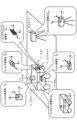
- FIG. 1 is a diagram illustrating an example configuration of a robot that is an example of a moving device according to the present disclosure.
- FIG. 2 is a diagram illustrating a coordinate system of a sensor mounted on a robot and a robot coordinate system.
- FIG. 2 is a diagram illustrating a coordinate transformation matrix that performs coordinate transformation between different coordinate systems.
- FIG. 2 is a diagram illustrating a coordinate transformation matrix that performs coordinate transformation between different coordinate systems.
- FIG. 3 is a diagram illustrating an example of individual differences among manufacturing robots.
- FIG. 7 is a diagram illustrating a problem when processing using a coordinate transformation matrix calculated based on the designed sensor mounting position and orientation is performed when the sensor is installed in a position and orientation different from the designed one.
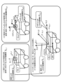
- FIG. 1 is a diagram illustrating an example configuration of a calibration system including a calibration execution device according to the present disclosure.
- FIG. 1 is a diagram illustrating an example configuration of a calibration system including a calibration execution device according to the present disclosure.
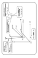
- FIG. 2 is a diagram illustrating a sensor coordinate system, which is a coordinate system of each sensor mounted on a robot, a robot coordinate system, and a scanner coordinate system.
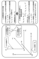
- FIG. 6 is a diagram illustrating an example of a point cloud ( L P L ) detected by LiDAR when a robot is running in a room with rectangular walls.
- FIG . 6 is a diagram illustrating a calculation process of a coordinate transformation matrix ( R T Shows part of the point cloud detected by LiDAR ( LPL ) and part of the point cloud detected by 3D scanner ( SPS ) when the robot is running in a room with rectangular walls. It is a diagram.
- FIG. 6 is a diagram illustrating a specific example of processing executed by a relative position calculation unit.
- FIG. 3 is a diagram illustrating an example of display data generated by a display information generation unit (visualized data generation unit) and output to a display unit.
- FIG. 3 is a diagram illustrating an example of display data generated by a display information generation unit (visualized data generation unit) and output to a display unit.
- FIG. 6 is a diagram illustrating an example of a display image on the display unit when the viewpoint position is changed.
- FIG. 2 is an explanatory diagram of an example of the configuration of an online calibration system including a calibration execution device according to a second embodiment.
- FIG. 2 is an explanatory diagram of an example of the configuration of an online calibration system including a calibration execution device according to a second embodiment.
- FIG. 1 is a diagram illustrating an example of the configuration of an online calibration system including a calibration execution device according to a second embodiment.
- FIG. 2 is a diagram illustrating a sensor coordinate system, which is a coordinate system of each sensor attached to a robot, a robot coordinate system, a fixed depth camera coordinate system, a chessboard coordinate system, and a map coordinate system.
- 7 is a diagram illustrating an example of the relationship between a coordinate system and a coordinate transformation matrix used in Example 2.
- FIG. FIG. 3 is a diagram illustrating a detailed configuration of a calibration execution device according to a second embodiment.
- FIG. 7 is a diagram illustrating an example of the configuration of an online calibration system including a calibration execution device according to a third embodiment.
- FIG. 7 is a diagram illustrating an example of the configuration of an online calibration system including a calibration execution device according to a third embodiment.
- FIG. 7 is a diagram illustrating an example of the configuration of an online calibration system including a calibration execution device according to a third embodiment.
- FIG. 2 is a diagram illustrating a sensor coordinate system, which is a coordinate system of each sensor attached to robot B, a robot B coordinate system, and a map coordinate system.
- FIG. 7 is a diagram illustrating an example of the relationship between a coordinate system and a coordinate transformation matrix used in Example 3;
- FIG. 7 is a diagram illustrating an example of the relationship between a coordinate system and a coordinate transformation matrix used in Example 3;
- FIG. 7 is a diagram illustrating a detailed configuration and processing of a calibration execution device according to a third embodiment.
- FIG. 7 is a diagram illustrating a detailed configuration and processing of a calibration execution device according to a third embodiment.
- FIG. 12 is a diagram illustrating calibration processing in Example 4.
- FIG. 7 is a diagram illustrating a configuration example of a calibration system including a calibration execution device according to a fourth embodiment.
- FIG. 7 is a diagram illustrating a detailed configuration and processing of a calibration execution device according to a fourth embodiment.
- FIG. 3 is a diagram illustrating an example of display data generated by a display information generation unit (visualized data generation unit) and output to a display unit.
- FIG. 3 is a diagram illustrating an example of display data generated by a display information generation unit (visualized data generation unit) and output to a display unit.
- FIG. 2 is a diagram illustrating an example of the hardware configuration of a calibration execution device according to the present disclosure.
- sensors mounted on mobile devices such as robots and self-driving vehicles
- cameras and LiDAR Light Detection and Ranging
- LiDAR Light Detection and Ranging
- each of these multiple sensors individually measures the surrounding environment, for example, the distance and direction to an obstacle.
- the position and direction of obstacles are measured using each sensor's unique coordinate system.
- the camera uses, for example, a camera coordinate system with the camera lens position as the origin
- LiDAR uses, for example, the LiDAR coordinate system with the laser light output position within the LiDAR as the origin, to determine the coordinate position of the obstacle.
- the robot itself has its own robot coordinate system.
- the robot coordinate system for example, a coordinate system having an origin at the center position of the robot or the like is used.
- a coordinate system may be used in which the origin is a certain point on the robot ground plane, for example, the intersection of a perpendicular from the robot center position and the robot ground plane. In order for the robot to travel safely, it is necessary to accurately calculate the position information of obstacles in this robot coordinate system.
- FIG. 1 shows an example of a robot 10 that is an example of a moving device according to the present disclosure.
- the robot 10 shown in FIG. 1 is a robot that analyzes the surrounding environment based on sensor detection information and moves autonomously.
- the robot 10 is equipped with a plurality of different sensors 11 to 14. That is, a camera 11, a depth camera 12, a LiDAR 13, an IMU 14, and these sensors are installed.
- the depth camera 12 is a camera that detects object distance, such as a stereo camera, for example.
- LiDAR 13 is a sensor that measures the distance to an obstacle using laser light.
- the IMU is an inertial measurement unit, and is a sensor that detects acceleration, angular velocity, etc. of the robot 10.
- Each of these sensors 11 to 14 calculates sensor detection values based on the sensor's own coordinate system, such as the coordinate position of an obstacle, based on the sensor's own coordinate system.
- FIG. 2 shows an example of a coordinate system corresponding to each of the sensors 11 to 14 and a robot coordinate system.
- FIG. 2 shows the following coordinate systems.
- R Robot coordinate system
- ⁇ R Camera coordinate system
- ⁇ C Camera coordinate system
- D Depth camera coordinate system
- L LiDAR coordinate system
- I IMU coordinate system
- ( ⁇ ) is used as a symbol indicating a coordinate system.
- ( ⁇ A ) means the coordinate system of device A.
- the robot coordinate system ( ⁇ R ) has its origin at the intersection of a perpendicular line from the center position of the robot 10 and the robot ground plane, the X axis is in front of the robot 10, the Y axis is in the left side direction, and the upward direction is the This is a coordinate system with the Z axis.
- the camera coordinate system ( ⁇ C ) is, for example, a coordinate system with the lens position of the camera 11 as the origin, the front optical axis direction of the camera 11 as the Z axis, the lower surface direction as the Y axis, and the right direction as the X axis. be.
- the depth camera coordinate system ( ⁇ D ) has, for example, the center of gravity of the depth camera 12 as its origin, the front optical axis direction of the depth camera 12 as the Z axis, the lower surface direction as the Y axis, and the right direction as the X axis. It is a coordinate system.
- the LiDAR coordinate system ( ⁇ L ) is a coordinate system having, for example, the center of gravity of the LiDAR 13 as its origin, the front of the LiDAR 10 as the X axis, the left side direction as the Y axis, and the upward direction as the Z axis.
- the IMU coordinate system ( ⁇ I ) is a coordinate system whose origin is, for example, the center of gravity of the IMU 14, the X axis is in front of the IMU 10, the Y axis is in the left side direction, and the Z axis is in the upper direction.
- the robot coordinate system of the robot 10 and the coordinate system of each sensor are different.
- the sensor such as the depth camera 12 uses the coordinates of the obstacle in the depth camera coordinate system ( ⁇ D ) as the position of the obstacle. The position will be calculated.
- the robot 10 calculates the coordinate position of the obstacle in the robot coordinate system ( ⁇ R ) based on the coordinate position of the obstacle in the depth camera coordinate system ( ⁇ D ), and calculates the distance from the robot 10 to the obstacle. It performs control such as acquiring the direction and selecting a driving route that avoids contact with obstacles.
- a coordinate transformation matrix (T) is used in the coordinate transformation process.
- the coordinate position (x D , y D , z D ) of the depth camera coordinate system ( ⁇ D ) of a certain point P in space is changed to the coordinate position (x R , y R , z ) of the robot coordinate system ( ⁇ R ) .
- a coordinate transformation matrix ( R T D ) is used in the coordinate transformation process to transform the image into R ).
- the coordinate position (x L , y L , z L ) of the LiDAR coordinate system ( ⁇ L ) of point P is converted to the coordinate position (x R , y R , z R ) of the robot coordinate system ( ⁇ R ).
- a coordinate transformation matrix ( LTC ) is used for the coordinate transformation process.
- B P indicates the position coordinates (x A , y A , z A ) of the point P in the coordinate system A
- B P indicates the position coordinates (x B , y B , z A ) of the point P in the coordinate system B.
- B ) means.
- the T in the upper right represents transposition.
- the coordinate transformation matrix is a homogeneous transformation matrix with 4 rows and 4 columns. Therefore, when performing coordinate transformation on the position coordinates of point P, the product is calculated in the form of homogeneous coordinates, which is a four-dimensional column vector with 1 added as the fourth element.
- the coordinate transformation matrix A T B which is a homogeneous transformation matrix in a three-dimensional space, is a 4-by-4 homogeneous transformation matrix shown in (Equation 1) below.
- the upper left 3 rows and 3 columns are rotation matrices representing angles
- the upper right 3 rows and 1 column are translation matrices
- the bottom row is (0, 0, 0, 1).
- the rotation matrix with 3 rows and 3 columns is a three-dimensional column vector in which each column from the left represents the direction of the x-axis, y-axis, and z-axis, and is a unit vector with a length of 1. Coordinate transformations can be executed one after another by multiplying these homogeneous transformation matrices.
- the upper left subscript (A) of the coordinate transformation matrix A T B is the reference coordinate system corresponding to the coordinate system after the transformation, and the lower right subscript (B) is the coordinate system to be transformed.
- a coordinate transformation matrix that performs coordinate transformation between different coordinate systems will be described with reference to FIGS. 3 and 4.
- FIG. 3 shows the robot 10 equipped with the LiDAR 13.
- the robot 10 has a robot coordinate system ( ⁇ R ) unique to the robot, and the LiDAR 13 has a LiDAR coordinate system ( ⁇ L ) unique to LiDAR.
- the right side of FIG. 3 shows both the robot coordinate system ( ⁇ R ) and the LiDAR coordinate system ( ⁇ L ).
- the robot coordinate system ( ⁇ R ) is, for example, a coordinate system indicated by a solid line whose origin (OR) is the intersection of a perpendicular from the center position of the robot 10 and the ground plane of the robot in contact with the robot.
- the LiDAR coordinate system ( ⁇ L ) is a coordinate system indicated by a dotted line with the center of gravity of the LiDAR 13 as the origin (OL).
- the robot coordinate system ( ⁇ R ) shown by the solid line and the LiDAR coordinate system ( ⁇ L ) shown by the dotted line are different systems with different origins. It becomes a coordinate system.
- Position coordinates ( LP ) of point P on LiDAR coordinate system ( ⁇ L ) ( zL , yL , zL )
- Position coordinates ( R P) of point P on the robot coordinate system ( ⁇ R ) (z R , y R , z R )
- the robot 10 calculates the coordinate position of the obstacle in the robot coordinate system ( ⁇ R ) from the coordinate position of the obstacle on the LiDAR coordinate system ( ⁇ L ), and moves from the robot 10 to the obstacle. It is possible to control the vehicle by acquiring the distance and direction of the vehicle and selecting a travel route that does not come into contact with obstacles.
- the coordinate transformation matrix can be determined based on design information such as the mounting position and angle of each sensor for the robot.
- design information such as the mounting position and angle of each sensor for the robot.
- a process of calculating a coordinate transformation matrix unique to the combination of a robot and a sensor is executed as a sensor calibration process.
- FIG. 5 is a diagram illustrating an example of individual differences among manufacturing robots.
- FIG. 5(1) is a diagram showing an example of a designed mounting position and posture (tilt) of LiDAR on a robot. In terms of design, it is assumed that the LiDAR 13 is mounted vertically at the center of the upper surface of the robot 10.
- FIG. 5(2) shows an example of the LiDAR mounting position and posture (tilt) of an actually manufactured robot.
- the LiDAR mounting position is slightly shifted to the rear left from the center of the upper surface of the robot, and is mounted at an angle.
- the difference between the designed and actual configurations is emphasized.
- the LiDAR mounting positions are also different, and the inclinations are also various.
- FIG. 6 shows the following figures.
- LiDAR coordinate system ( ⁇ L1 ) corresponding to the designed LiDAR mounting position and posture
- LiDAR coordinate system ( ⁇ L2 ) corresponding to the LiDAR mounting position and posture of the manufactured robot
- ⁇ L1 LiDAR coordinate system
- ⁇ L2 LiDAR coordinate system
- the robot shown in FIG. 6(1) has the designed robot configuration shown in FIG. 5(1), and LiDAR is mounted vertically at the center position on the top surface of the robot.
- robot a shown in FIG. 6(2) corresponds to robot a shown in FIG. 5.
- the LiDAR mounting position is slightly shifted to the rear left from the center of the top surface of the robot, and is mounted at an angle.
- LiDER in FIGS. 6(1) and 6(2) each show a LiDAR coordinate system.
- the designed LiDAR coordinate system ( ⁇ L1 ) shown in (1) has three axes (xyz axes) corresponding to the posture (tilt) of the LiDAR, with the designed center of gravity of the LiDAR as the origin (OL1), that is, as shown in the figure. It is a coordinate system having XL1 axis, YL1 axis, and ZL1 axis.
- the LiDAR coordinate system ( ⁇ L2 ) of the robot a shown in (2) has the center of gravity of the LiDAR of the robot a as the origin (OL2), and has three axes (x, y, and z axes) according to the posture (tilt) of the LiDAR, that is, the This is a coordinate system having two XL axes, two YL axes, and two ZL axes as shown in FIG.
- the origin position is different between the designed LiDAR mounting position and posture-compatible LiDAR coordinate system ( ⁇ L1 shown in (1) and the LiDAR mounting position and posture-compatible LiDAR coordinate system ( ⁇ L2 ) of robot a shown in (2). , and the directions of each coordinate axis are also different.
- FIG. 6(3) is a diagram showing two coordinate systems together in a three-dimensional space in which the origins (OR) of the robot coordinate systems are aligned.
- the designed LiDAR coordinate system ( ⁇ L1 ) and the LiDAR coordinate system ( ⁇ L2 ) of robot a differ in the origin position and also in the direction of each coordinate axis.
- FIG. 7 also shows the robot coordinate system ( ⁇ R ) of robot 10.
- the robot coordinate system is a coordinate system whose origin (OR) is, for example, a certain point on the robot ground plane, such as the intersection of a perpendicular from the robot center position and the robot ground plane.
- Robot coordinate system ( ⁇ R ) shown by a solid line A designed LiDAR coordinate system ( ⁇ L1 ) corresponding to the designed position and orientation of LiDAR, LiDAR coordinate system ( ⁇ L2 ) corresponding to the LiDAR position and orientation of robot a,
- the three-dimensional position coordinates (x, y, z) in these three coordinate systems are as follows, as shown in the figure.
- the above relational expression holds true.
- the calibration process shown in FIG. 8(2) ie, the calibration process for calculating a unique coordinate transformation matrix for each sensor mounted on the robot, is required for each robot.
- the calibration execution device of the present disclosure thus executes a calibration process that calculates a coordinate transformation matrix unique to the combination of a robot and a sensor mounted on the robot, and further calculates the coordinate transformation matrix calculated as a result of the calibration. It has a configuration that makes it possible to visually confirm whether or not the calculation is correct.
- the configuration of the apparatus of the present disclosure and a plurality of embodiments for executing processing will be sequentially described.
- Example 1 Regarding the configuration and processing of the calibration execution device
- the configuration and processing of the calibration execution device according to Example 1 of the present disclosure will be described below.
- FIG. 9 is a diagram illustrating an example configuration of a calibration system 50 including the calibration execution device 30 of the present disclosure.
- a calibration system 50 shown in FIG. 9 is a system that includes a robot 10, a 3D scanner 20, and a calibration execution device 30.
- the robot 10 is an autonomous mobile robot and is equipped with a plurality of sensors.
- the robot 10 is an example of a moving device according to the present disclosure, and the moving device according to the present disclosure includes various types of moving objects such as self-driving vehicles in addition to robots.
- the 3D scanner 20 measures the three-dimensional shape of surrounding objects.
- the 3D scanner 20 has a built-in color camera and can acquire color information in addition to the three-dimensional shape.
- the 3D scanner 20 performs a scanning process that irradiates a laser beam over 360 degrees of the surrounding area and inputs the reflected light, measures distances to surrounding objects, and obtains a three-dimensional shape of the surrounding environment.
- the robot 10 is similar to the robot 10 described above with reference to FIG. 1, and is a robot that analyzes the surrounding environment based on sensor detection information and moves autonomously. As shown in FIG. 9, the robot 10 is equipped with a plurality of different sensors 11-14. That is, a camera 11, a depth camera 12, a LiDAR 13, an IMU 14, and these sensors are installed.
- the depth camera 12 is a camera that detects object distance, such as a stereo camera.
- the LiDAR 13 is a sensor that measures the distance to an obstacle using laser light, as described above.
- the IMU is an inertial measurement unit, and is a sensor that detects acceleration, angular velocity, etc. of the robot 10.
- the robot 10 shown in FIG. 9 is equipped with a camera 11, a depth camera 12, a LiDAR 13, and an IMU 14 as a plurality of different types of sensors.
- the configuration is not limited to this, and configurations in which various other types of sensors are installed may be used.
- the processing of the present disclosure is applicable not only to a configuration in which multiple types of sensors are installed, but also to a configuration in which a single sensor is installed.
- the sensors 11 to 14 attached to the robot 10 shown in FIG. calculate.
- the calibration execution device 30 can be configured by, for example, a data processing device such as a PC.
- the calibration execution device 30 has a configuration capable of communicating with the robot 10 and the 3D scanner 20.
- the calibration execution device 30 inputs sensor detection information of each of the sensors 11 to 14 mounted on the robot 10, and further inputs scanner detection information from the 3D scanner 20.
- the calibration execution device 30 executes a calibration process for each of the sensors 11 to 14 mounted on the robot 10 based on this input information. Specifically, a process of calculating a coordinate transformation matrix corresponding to the sensor is executed.
- the sensor-compatible coordinate transformation matrix is a coordinate transformation matrix that transforms position coordinates on a sensor-specific coordinate system to position coordinates on a robot coordinate system.
- the calibration execution device 30 further displays display data, which is visualization data for checking the calibration results, which makes it possible to visually check whether the coordinate transformation matrix calculated as the calibration result has been calculated correctly. Generate and output to the display unit.
- the visualization data for checking the calibration results is image data that allows checking whether the coordinate transformation matrix corresponding to the sensor has been calculated correctly. A specific example of this image data will be described later.
- the calibration execution device 30 inputs detection information of each sensor from the robot 10, and further inputs scanner detection information (surrounding three-dimensional shape information) from the 3D scanner 20.
- the calibration execution device 30 uses this input information to execute a calibration process that calculates a coordinate transformation matrix corresponding to each sensor of the robot 10.
- the coordinate transformation matrix corresponding to each sensor calculated as a result of the calibration process executed by the calibration execution device 30 is transmitted to the robot 10 and stored in the storage unit within the robot 10.
- the robot 10 converts the position coordinates on the coordinate system unique to each sensor to the position coordinates on the robot coordinate system using the coordinate transformation matrix corresponding to the sensor stored in the storage unit. Based on the subsequent position coordinates on the robot coordinate system, the relative positions of surrounding obstacles with respect to the robot 10 are analyzed, and autonomous movement is performed by selecting a running route that avoids collisions or contact with obstacles.
- the calibration system 50 shown in FIG. 9 is an example of a system in which the robot 10 and the calibration execution device 30 are configured as separate devices, for example, as shown in FIG. A configuration such as a calibration system 50b that integrates the device 30 may be used.
- the calibration execution device 30 within the robot 10 executes a calibration process that calculates a coordinate transformation matrix corresponding to each sensor mounted on the robot 10.
- the scanner coordinate system which is the coordinate system of the 3D scanner 20, will be described.
- FIG. 11 shows the following coordinate systems.
- R Robot coordinate system
- ⁇ R C
- C Camera coordinate system
- ⁇ C Depth camera coordinate system
- ⁇ D L
- ⁇ L LiDAR coordinate system
- I IMU coordinate system
- ⁇ I IMU coordinate system
- S Scanner coordinate system
- the robot coordinate system ( ⁇ R ) has its origin at the intersection of a perpendicular line from the center position of the robot 10 and the robot ground plane, the X axis is in front of the robot 10, the Y axis is in the left side direction, and the upward direction is the This is a coordinate system with the Z axis.
- the camera coordinate system ( ⁇ C ) is, for example, a coordinate system with the lens position of the camera 11 as the origin, the front optical axis direction of the camera 11 as the Z axis, the lower surface direction as the Y axis, and the right direction as the X axis. be.
- the depth camera coordinate system ( ⁇ D ) has, for example, the center of gravity of the depth camera 12 as its origin, the front optical axis direction of the depth camera 12 as the Z axis, the lower surface direction as the Y axis, and the right direction as the X axis. It is a coordinate system.
- the LiDAR coordinate system ( ⁇ L ) is a coordinate system having, for example, the center of gravity of the LiDAR 13 as its origin, the front of the LiDAR 10 as the X axis, the left side direction as the Y axis, and the upward direction as the Z axis.
- the IMU coordinate system ( ⁇ I ) is a coordinate system whose origin is, for example, the center of gravity of the IMU 14, the X axis is in front of the IMU 10, the Y axis is in the left side direction, and the Z axis is in the upper direction.
- the scanner coordinate system ( ⁇ S ) is a coordinate system in which the center of gravity of the 3D scanner 20 is the origin, the orthogonal axes of the horizontal plane are the XY axes, and the axis extending vertically upward is the Z axis.
- the robot coordinate system of the robot 10 As shown in FIG. 11, the robot coordinate system of the robot 10, the coordinate systems of the sensors 11 to 14, and the coordinate systems of the 3D scanner 20 are different from each other.
- each sensor of the robot 10 obtains the coordinate position of an obstacle using a coordinate system specific to each sensor.
- the depth camera 12 calculates the coordinate position of the obstacle in the depth camera coordinate system ( ⁇ D ) as the position of the obstacle.
- the robot 10 calculates the coordinate position of the obstacle on the robot coordinate system ( ⁇ R ) based on the coordinate position of the obstacle in the depth camera coordinate system ( ⁇ D ), and calculates the distance from the robot 10 to the obstacle.
- the vehicle performs control such as acquiring the direction and direction and selecting a route that avoids contact with obstacles.
- the position of the obstacle P in the depth camera coordinate system ( ⁇ D ) calculated using the captured image of the depth camera 12 (depth camera coordinate position (x D , y D , z D )), or the position calculated by LiDAR 13 Regarding the position of the obstacle P in the LiDAR coordinate system ( ⁇ L ) (LiDAR coordinate position (x L , y L , z L )), the position of the obstacle P in the robot coordinate system ( ⁇ R ) (robot coordinate position ( R , y R , z R )).
- the coordinate transformation matrix (T) is used in the coordinate transformation process.
- the coordinate position (x D , y D , z D ) of the depth camera coordinate system ( ⁇ D ) of a certain point P in space is changed to the coordinate position (x R , y R , z ) of the robot coordinate system ( ⁇ R ) .
- a coordinate transformation matrix R T D is used in the coordinate transformation processing to transform the coordinates into R ).
- the coordinate position (x L , y L , z L ) of the LiDAR coordinate system ( ⁇ L ) of point P is converted to the coordinate position (x R , y R , z R ) of the robot coordinate system ( ⁇ R ).
- a coordinate transformation matrix ( RTL ) is used for the coordinate transformation processing.
- ( AP ) indicates the position coordinates ( xA , yA , zA ) of point P in coordinate system A
- ( BP ) indicates the position coordinates (xB, zA) of point P in coordinate system B.
- y B , z B ).
- the calibration execution device 30 shown in FIGS. 9 and 10 executes the process of calculating a coordinate transformation matrix specific to the combination of the robot and the sensor as a sensor calibration process.
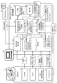
- FIG. 12 shows a detailed configuration of the calibration execution device 30 and data input by the calibration execution device 30 from the robot 10 and the 3D scanner 20.
- the calibration execution device 30 includes a calibration execution unit 31, a relative position calculation unit 32, an external coordinate system compatible coordinate transformation matrix calculation unit 33, a display information generation unit (visualization data generation unit) 34, an input It has a section 35 and a display section 36.
- FIG. 12 shows a camera 11, a depth camera 12, a LiDAR 13, and an IMU 14 as the sensors 11 to 14 mounted on the robot 10.
- the types of sensors mounted on the robot 10 are not limited to these, and a configuration in which various other types of sensors are mounted may be used.
- the processing of the present disclosure is applicable not only to a configuration in which multiple types of sensors are installed, but also to a configuration in which a single sensor is installed.
- the calibration execution unit 31 of the calibration execution device 30 calculates a coordinate transformation matrix for each of the sensors 11 to 14 mounted on the robot 10. That is, the calibration execution unit 31 inputs sensor detection information etc. from each sensor 11 to 14 of the robot 10 and executes a process of calculating a coordinate transformation matrix corresponding to each sensor.
- the calibration execution device 30 receives the following information from each sensor 11 to 14 of the robot 10. From the camera 11, a captured image of the camera 11 and internal parameters of the camera 11 From the depth camera 12, a distance image (depth image) that is a captured image of the depth camera 12, and internal parameters of the depth camera 12 From the LiDAR 13, a detected value of LiDAR Point cloud ( L P L ) information from the IMU 14, angular velocity, acceleration, etc. of the robot 10, which are IMU detection information.
- the calibration execution device 30 inputs the above information from each sensor 11 to 14 of the robot 10.
- the point cloud ( LPL ) information which is the LiDAR detection value inputted from the LiDAR 13 , is point cloud information indicating the object position in the three-dimensional space around the LiDAR 13.
- ( LPL ) indicates point cloud data on the LiDAR coordinate system.
- the subscript (L) on the upper left of ( L P L ) means the coordinate system, and (P L ) means the three-dimensional point group of LiDAR.
- the point cloud ( L P L ) detected by the LiDAR 13 indicates the object position in the three-dimensional space around the LiDAR 13.
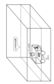
- the point group becomes a point group indicating the positions of the walls in four directions, as shown in FIG.
- the LiDAR 13 is a type of LiDAR that scans a single laser beam in the horizontal direction, and can obtain a point group that looks like a wall surface sliced horizontally by the laser beam.
- the shape of this sliced cross section depends on the height and orientation of the LiDAR 13 installed.
- the calibration execution unit 31 inputs sensor detection information etc. from each sensor 11 to 14 of the robot 10 and executes the following process of calculating a coordinate transformation matrix corresponding to each sensor.
- a coordinate matrix for converting the sensor coordinate system of each sensor 11 to 14 mounted on the robot 10 into the robot coordinate system ( ⁇ R ) will be indicated as ( R T X ).
- X means identifiers of various sensors.
- the calibration execution unit 31 of the calibration execution device 30 calculates the coordinate transformation matrix ( R T X ) of each of the sensors 11 to 14 mounted on the robot 10.
- the process of calculating the coordinate transformation matrix is performed using a known calibration technique. Specifically, it can be calculated by applying, for example, the structure described in the following non-patent literature.
- Non-patent document 2 (Dhallet al. Ankit,. LiDAR-camera calibration using 3D-3D point correspondences. arXiv preprint arXiv:1705.09785, 2017.)
- Non-patent document 3 (Banerjeeet al. Koyel,. Online camera lidar fusion and object detection on hybrid data for autonomous driving. 2018 IEEE Intelligent Vehicles Symposium (IV). IEEE, 2018.)
- Non-patent document 4 (PusztaiIvn Eichhardt, and Levente Hajder.Zoltn,. Accurate calibration of multi-lidar-multi-camera systems. Proceedings of the IEEE International Conference on Computer Vision Workshops., 2017.)
- Non-patent document 5 (Irene FassiLegnaniGiovanni.
- the calibration execution unit 31 inputs each sensor detection information etc. from each sensor 11 to 14 of the robot 10 and creates a coordinate transformation matrix ( R T X ) that converts the coordinate system of each sensor into the robot coordinate system. Execute the calculation process. Note that, as explained earlier using (Formula 1), the coordinate transformation matrix R T It is shown as a four-column homogeneous transformation matrix.
- the upper left 3 rows and 3 columns represent the rotation matrix
- the upper right 3 rows and 1 column represent the translation.
- the matrix elements of the coordinate transformation matrix ( R T (a) (R 00 , R 10 , R 20 ) is the X-axis direction of the sensor coordinate system ( ⁇ (b) (R 01 , R 11 , R 21 ) is the Y-axis direction of the sensor coordinate system ( ⁇ (c) (R 02 , R 12 , R 22 ) is the Z-axis direction of the sensor coordinate system ( ⁇ (d) (t 0 , t 1 , t 2 ) are the origin position coordinates of the sensor coordinate system ( ⁇ Note that each direction of the coordinate axes (X-axis, Y-axis, Z-axis) shown in (a) to (d) above and the origin position are directions in the robot coordinate system ( ⁇ R ), which is the coordinate system after coordinate transformation, and the coordinate position.
- the relative position calculation unit 32 executes alignment processing between the scanner coordinate system ( ⁇ S ) of the 3D scanner 20 and the robot coordinate system ( ⁇ R ) of the robot 10 .
- the relative position calculation unit 32 inputs a colored point cloud ( SPS ) from the 3D scanner 20, inputs a point cloud ( LPL ) from the LiDAR 13 of the robot 10, and uses these input point cloud information to calculate , executes alignment processing between the scanner coordinate system ( ⁇ S ) and the robot coordinate system ( ⁇ R ).
- SPS colored point cloud
- LPL point cloud
- FIG. 15 shows a part of the point cloud ( L P L ) detected by the LiDAR 13 when the robot 10 is running in a room with rectangular walls, and a portion of the point cloud (L P L ) detected by the 3D scanner 20. It is a figure showing a part of point group ( SPS ) to detect.
- the LiDAR 13 is a type of LiDAR that scans a single laser beam in the horizontal direction, and can obtain a point group that looks like the laser beam slices a wall surface horizontally.
- the shape of this sliced cross section depends on the height and orientation of the LiDAR 13 installed.
- the point cloud input from the 3D scanner 20 is a point cloud representing the surface of the object, which is 360 degrees horizontally and in a vertical direction from below to vertically above, excluding the area directly below the 3D scanner 20. .
- ( s p si ) indicates one point that constitutes the point group ( S P S ).
- ( S x Si , S y Si , S z Si ) is the coordinate position of the point ( s psi ) .
- point group coordinate conversion processing for converting a point group on a certain coordinate system to a point group on a different coordinate system can be executed by applying a point group coordinate conversion formula.
- a point cloud that converts a depth camera detection point group ( S P S ) indicated by a depth camera coordinate system ( ⁇ D ) into a scanner coordinate system point group ( S P S ) indicated by a 3D scanner coordinate system ( ⁇ S ).
- the coordinate transformation formula ( S P D ) is shown as (Equation 3) below. Calculations are performed using four-dimensional homogeneous coordinates.
- the relative position calculation unit 32 first aligns the point cloud of the LiDAR 13 and the point cloud of the 3D scanner 20.
- the relative position calculation unit 32 first detects the floor surface (robot ground surface) from the point group of the 3D scanner 20 and calculates the height (H S ) of the 3D scanner 20 from the floor.
- the point cloud ( SPS ) input from the 3D scanner 20 includes a point cloud on the floor surface (robot ground surface).
- the floor surface (robot ground surface) has a large area and is located below the 3D scanner 20, and the normal line of the surface is almost parallel to the z-axis direction of the coordinate system of the 3D scanner 20, so it is easy to touch the floor surface (robot ground surface). can be detected.
- the relative position calculation unit 32 calculates the height (H L ) from the floor surface (robot ground surface) to the LiDAR 13. This height is a value located in the 3rd row and 4th column of the 4th row and 4th column of the coordinate transformation matrix ( R T L ) of the LiDAR 13 obtained by the calibration execution unit 31.
- (t 0 , t 1 , t 2 ) indicates the origin position coordinates of the sensor coordinate system ( ⁇
- This value corresponds to the difference in height (Z direction) from the origin of the lidar coordinate system ( ⁇ L ). That is, the value corresponds to the height (H L ) from the floor (robot ground plane) to the LiDAR 13.
- the relative position calculating unit 32 utilizes the calculated height (H L ) of the LiDAR 13, that is, the height (H L ) from the floor surface (robot ground surface) to the LiDAR 13, as shown in FIG.
- a part of the point cloud is extracted from the spherical point cloud ( SPS ) input from the 3D scanner 20.
- the point group located at the height (H SL ) (H S ) ⁇ (H L ) of the origin position of the LiDAR coordinate system ( ⁇ L ) from the origin of the scanner coordinate system ( ⁇ S ) of the 3D scanner 20 Extract ( SP HSL ).
- the relative position calculation unit 32 calculates the difference between a part of the point cloud ( S P HSL ) extracted from the spherical point cloud ( S P S ) input from the 3D scanner 20 and the point cloud of the LiDAR 13. Perform alignment.
- the positioning process of the point cloud can be executed using a known existing process such as ICP (Iterative Closest Point).
- ICP Intelligent Closest Point
- the relative position calculation unit 32 aligns the point cloud of the LiDAR 13 based on a part of the point cloud ( SP HSL ) extracted by slicing from the point cloud ( SPS ) input from the 3D scanner 20.
- a coordinate transformation matrix ( S T L ) necessary for the calculation is calculated according to the following (Equation 4).
- the coordinate transformation matrix ( S T L ) shown in the above (Equation 4) transforms a point group on the LiDAR coordinate system ( ⁇ L ) of the LiDAR 13 to a point group on the scanner coordinate system ( ⁇ S ) of the 3D scanner 20. This is the conversion formula for
- Equation 4 is based on a part of the point cloud ( S P HSL ) sliced and extracted from the point cloud ( S P S ) input from the 3D scanner 20 and points on the LiDAR coordinate system ( ⁇ L ).
- the problem is to find a coordinate transformation matrix ( T ) that minimizes the positional error with respect to the group ( LPL ).
- the coordinate transformation matrix ( S T L ) calculated by the above (Equation 4) can be obtained by repeated convergence calculations of ICP.
- This coordinate transformation matrix ( S T L ) is a coordinate transformation matrix that transforms the LiDAR coordinate system ( ⁇ L ) of the LiDAR 13 into the scanner coordinate system ( ⁇ S ) of the 3D scanner 20.
- the external coordinate system compatible coordinate transformation matrix calculation unit 33 receives the following coordinate transformation matrix as input from the calibration execution unit 31.
- the external coordinate system compatible coordinate transformation matrix calculation unit 33 further receives the following coordinate transformation matrix from the relative position calculation unit 32.
- the external coordinate system compatible coordinate transformation matrix calculation unit 33 inputs these plural coordinate transformation matrices and transforms the coordinate system ( ⁇ X ) of each sensor 11 to 14 of the robot 10 into the scanner coordinate system ( ⁇ S ).
- a coordinate transformation matrix ( STX ) is calculated.
- a coordinate transformation matrix (S T C ) for converting the camera coordinate system ( ⁇ C ) corresponding to the camera 11 into the scanner coordinate system ( ⁇ S ) can be calculated according to the following (Equation 5a).
- Equation 5a The coordinate transformation matrix shown on the right side of the above (Equation 5a) can all be calculated based on the input value or input value from the relative position calculation unit 32 or the calibration execution unit 31.
- the coordinate transformation matrix ( S T L ) is a coordinate transformation matrix ( S T L ) that transforms the LiDAR coordinate system ( ⁇ L ) of the LiDAR 13 into the scanner coordinate system ( ⁇ S ) of the 3D scanner 20, and the relative position It is input from the calculation unit 32.
- ( R T L ) ⁇ 1 is the inverse matrix of the coordinate transformation matrix ( R T L ), and the coordinate transformation matrix ( R T L ) input from the calibration execution unit 31, that is, the LiDAR coordinate system of the LiDAR 13 ( It can be calculated from a LiDAR compatible coordinate transformation matrix ( R T L ) that transforms ⁇ L ) into the robot coordinate system ( ⁇ R ).
- the coordinate transformation matrix ( R T C ) is a camera-compatible coordinate transformation matrix ( R T C ) that transforms the camera coordinate system ( ⁇ C ) of the camera 11 into the robot coordinate system ( ⁇ R ) , and is It is input from 31.
- the external coordinate system compatible coordinate transformation matrix calculation unit 33 uses the input value from the relative position calculation unit 32 or the calibration execution unit 31, or a matrix that can be calculated based on the input value, to convert the camera coordinate system.
- a coordinate transformation matrix (S T C ) that transforms ( ⁇ C ) into the scanner coordinate system ( ⁇ S ) is calculated.
- the external coordinate system compatible coordinate transformation matrix calculation unit 33 executes similar processing for each sensor mounted on the robot 10.
- a coordinate transformation matrix (S T D ) that transforms the depth camera coordinate system ( ⁇ D ) corresponding to the depth camera 12 into the scanner coordinate system ( ⁇ S ) is calculated according to the following (Equation 5b).
- Equation 5b The coordinate transformation matrix shown on the right side of the above (Equation 5b) can all be calculated based on the input value or input value from the relative position calculation unit 32 or the calibration execution unit 31.
- the coordinate transformation matrix ( S T L ) for converting the LiDAR coordinate system ( ⁇ L ) compatible with LiDAR 13 into the scanner coordinate system ( ⁇ S ) is input from the relative position calculation unit 32, and is a coordinate transformation matrix compatible with the external coordinate system. No new calculation processing by the calculation unit 33 is required.
- a coordinate transformation matrix (S T I ) that transforms the IMU coordinate system ( ⁇ I ) compatible with the IMU 14 into the scanner coordinate system ( ⁇ S ) is calculated according to the following (Equation 5c).
- the external coordinate system compatible coordinate transformation matrix calculation unit 33 calculates a coordinate transformation matrix (S T X ) that transforms the coordinate system ( ⁇ ) is calculated.
- the coordinate transformation matrix ( S T X ) calculated by the external coordinate system compatible coordinate transformation matrix calculation unit 33 , that is, the coordinate system ( ⁇
- the coordinate transformation matrix ( S T X ) calculated by the external coordinate system compatible coordinate transformation matrix calculation unit 33 , that is, the coordinate system ( ⁇ ).
- the coordinate transformation matrix ( S T X ) calculated by the external coordinate system compatible coordinate transformation matrix calculation unit 33 is the following coordinate transformation matrix ( S T X ).
- the display information generation unit (visualized data generation unit) 34 calculates the coordinates of each sensor 11 to 14 of the robot 10 based on these coordinate transformation matrices ( S T X ) calculated by the external coordinate system compatible coordinate transformation matrix calculation unit 33.
- the output signal is output to the section 36.
- the input unit 35 is configured with a mouse, a keyboard, etc., and inputs viewpoint information of a three-dimensional image drawn on the display unit 36 by the display information generation unit (visualization) data generation unit 34.
- the display information generation unit (visualized data generation unit) 34 determines a viewpoint direction based on the viewpoint information input from the input unit 35, and displays three-dimensional image data of the robot 10 observed from the determined viewpoint direction on the display unit. Output to 36.
- the three-dimensional image data of the robot 10 generated by the display information generating section (visualized data generating section) 34 and output to the display section 36 is a three-dimensional image shown on the scanner coordinate system ( ⁇ S ), and the three-dimensional image data of the robot 10 is This is an image in which the coordinate axes (X-axis, Y-axis, Z-axis) constituting the coordinate system ( ⁇ X ) of each sensor 11 to 14 of the robot 10 are superimposed on the original image.
- FIG. 17 shows an example of display data generated by the display information generation unit (visualized data generation unit) 34 and output to the display unit 36.
- a three-dimensional image of the robot 10 as shown in FIG. 17 is displayed on the display unit 36 of the calibration execution device 30.
- the three-dimensional image of the robot 10 is composed of, for example, a group of points indicating a three-dimensional image of an object such as the robot 10.
- the point cloud is a point cloud formed by information detected by the 3D scanner 20.
- the display data is generated using known computer graphics techniques, such as the configuration described in Non-Patent Document 7 (KamRyeol, et al. Hyeong. Rviz: a toolkit for real domain data visualization. Telecommunication Systems 60.2, 2015.). Can be generated.
- the coordinate axes ( X -axis, Y-axis, Z-axis) that make up the coordinate system ( ⁇ It is.
- the three-dimensional image on the scanner coordinate system ( ⁇ S ) of the robot 10 is a three-dimensional image generated by scanning processing (scanning processing) by the 3D scanner 20.
- This three-dimensional image of the robot 10 also includes three-dimensional images of each sensor mounted on the robot 10, that is, the camera 11, the depth camera 12, the LiDAR 13, and the IMU 14.
- the user inputs the IMU mounting position measured in advance to the calibration execution device 30, and the display information generation unit 34 generates a three-dimensional image of the IMU 14 based on the input information. Generate and output.
- the three-dimensional image of the robot 10 displayed on the display unit 36 includes sensor-compatible coordinate systems ( ⁇ The coordinate axes (X-axis, Y-axis, Z-axis) that make up the image ( X ) are also displayed.
- each axis may be displayed in a different color. It will be done. For example, the X-axis may be displayed in red, the Y-axis in green, and the Z-axis in blue.
- the display information generation unit 34 calculates the coordinate axes (X-axis, Y-axis, Z-axis) constituting these sensor-compatible coordinate systems ( ⁇ Obtained from the coordinate transformation matrix ( STX ).
- the external coordinate system compatible coordinate transformation matrix calculation unit 33 calculates the following coordinate transformation matrix ( S T X ) and outputs it to the display information generation unit 34.
- This coordinate transformation matrix ( S T C ) that transforms the camera coordinate system ( ⁇ C ) of the camera 11 into the scanner coordinate system ( ⁇ S )
- This coordinate transformation matrix ( S T C ) can be expressed as the following (Formula 1c), similar to (Formula 1) and (Formula 1b) described above.
- (R 00 , R 10 , R 20 ) is the X-axis direction of the sensor coordinate system
- ⁇ (b) (R 01 , R 11 , R 21 ) is the Y-axis direction of the sensor coordinate system
- ⁇ (c) (R 02 , R 12 , R 22 ) is the Z-axis direction of the sensor coordinate system
- ⁇ (d) (t 0 , t 1 , t 2 ) are the origin position coordinates of the sensor coordinate system ( ⁇
- each direction of the coordinate axes (X-axis, Y-axis, Z-axis) shown in (a) to (d) above and the origin position are directions in the scanner coordinate system ( ⁇ S ), which is the coordinate system after coordinate transformation, and the coordinate position.
- the coordinate axes (X-axis, Y-axis, Z-axis) constituting the camera coordinate system ( ⁇ C ) of the camera 11 are the coordinate transformation matrices calculated by the external coordinate system compatible coordinate transformation matrix calculation unit 33 described above.
- STC the coordinate transformation matrix calculation unit 33 described above.
- other sensor - compatible coordinate systems ( ⁇ Y-axis, Z-axis) are acquired from the coordinate transformation matrix ( S T X ) calculated by the external coordinate system compatible coordinate transformation matrix calculation unit 33 described above.
- the display example shown in FIG. 17 is a coordinate axis display example when the calibration process executed by the calibration execution unit 31 is successful and a correct coordinate transformation matrix is calculated.
- the origin is set at the lens position of the camera 11 mounted on the robot 10 shown in FIG.
- the X axis is set to the right.
- the camera coordinate system ( ⁇ C ) is displayed at the center position of the camera 11 in the three-dimensional image because the calibration process executed in the calibration execution unit 31 was successful and the correct coordinate transformation matrix was obtained. It means that it has been calculated.
- the calibration execution unit 31 receives sensor detection information from each of the sensors 11 to 14 of the robot 10, and executes the following process of calculating a coordinate transformation matrix corresponding to each sensor. For example, a process of calculating a camera-compatible coordinate transformation matrix ( R T C ) that transforms the camera coordinate system ( ⁇ C ) of the camera 11 into the robot coordinate system ( ⁇ R ) is executed.
- FIG. 17 Other sensor coordinate systems shown in FIG. 17, namely, the depth camera coordinate system ( ⁇ D ) of the depth camera 12, the LiDAR coordinate system ( ⁇ L ) of the LiDAR 13, and the IMU coordinate system ( ⁇ I ) of the IMU 14, are also used.
- the origin is set in the correct position and the coordinate axes are set in the correct direction.
- the sensor-compatible coordinate system ( ⁇ The display is different from the display of X ).
- FIG. 18 shows a display example when the coordinate transformation matrix generation process by the calibration execution unit 31 fails and a correct coordinate transformation matrix cannot be calculated.
- the camera coordinate system ( ⁇ C ) shown in FIG. 18 has no origin at the lens position of the camera 11 of the robot 10, and the origin is set at a position shifted from the camera 11. Further, the coordinate axes, which should originally have the Z axis in the front optical axis direction of the camera 11, the Y axis on the lower side, and the X axis on the right side, are tilted. This is clearly a different representation from the correct camera coordinate system ( ⁇ C ).
- the coordinate axes have correct positions and directions, and the calculation process of the LiDAR compatible coordinate transformation matrix ( R T L ) and the IMU compatible coordinate transformation matrix ( R T I ) in the calibration execution unit 31 is as follows. confirmed to be successful.
- the display unit 36 of the calibration execution device 30 of the present disclosure displays each image on the scanner coordinate system ( ⁇ S ) along with the three-dimensional image of the robot 10 shown on the scanner coordinate system ( ⁇ S ). An image in which the coordinate system ( ⁇ X ) corresponding to the sensor is superimposed is displayed.
- the user can calibrate the calibration execution unit 31 by checking the origin position and the direction (tilt) of the seat surface axis of the coordinate system ( ⁇ It becomes possible to determine whether the calibration process in , that is, the calculation process of the sensor corresponding target transformation matrix ( R T X ) was successful.
- the display information generation section (visualized data generation section) 34 determines the viewpoint direction based on the viewpoint information input from the input section 35, and determines the direction of the robot 10 observed from the determined viewpoint direction. Three-dimensional image data is output to the display section 36. The user can operate the viewpoint from the input unit 35 and observe the relative positional relationship between the point group representing the three-dimensional image of the object such as the robot 10 and the sensor coordinate transformation matrix in any direction and at any magnification.
- FIG. 19 shows an example of a display image on the display unit 36 when the viewpoint position is changed.
- FIG. 19(a) is an example of a display image when the robot 10 is observed from the front right side.
- FIG. 19(b) is an example of a display image when the robot 10 is observed from the front left side direction.
- FIG. 19(c) is an example of a display image when the robot 10 is observed from the lower side of the front right side.
- the external coordinate system compatible coordinate transformation matrix calculation unit 33 of the calibration execution device 30 shown in FIG. 12 converts the coordinate system ( ⁇
- An example of calculating a coordinate transformation matrix ( S T X ) for converting into ⁇ S ) has been described.
- the display information generation unit (visualization data generation unit) 34 calculates the coordinates of each sensor 11 to 14 of the robot 10 based on the coordinate transformation matrix ( S T X ) calculated by the external coordinate system compatible coordinate transformation matrix calculation unit 33.
- a "coordinate transformation matrix” is used as a method of expressing the coordinate system, position, and orientation of the sensors.
- the method of expressing the coordinate system, position and orientation of the sensors is not limited to the "coordinate transformation matrix", and other methods may be applied.
- a method for expressing the coordinate system, position, and orientation of sensors there is a known method of expressing the coordinate system, position, and orientation of sensors using a set of quaternions in which three numbers represent translation and four numbers represent rotation.
- a method that uses Euler angles which represent three numbers for translation and three numbers for rotation. Euler angles are a method commonly used in ROS (Robot Operating System) and the like.
- Embodiment 2 which will be described below, is an embodiment in which the sensor-compatible coordinate transformation matrix ( RTX ) is sequentially updated online while the robot 10 is running.
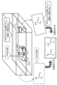
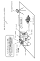
- FIG. 20 shows a configuration example of an online calibration system 60 including the calibration execution device 30 of the second embodiment.
- the online calibration system 60 shown in FIG. 20 is a system that includes a robot 100, a fixed depth camera 40, and a calibration execution device 30. Further, a chess board 45 is attached to the running surface of the robot 100. The chess board 45 is composed of regular black and white patterns.
- the robot 100 is an autonomous mobile robot and is equipped with multiple sensors. Note that the robot 100 is an example of a moving device according to the present disclosure, and the moving device according to the present embodiment also includes various types of moving objects such as self-driving vehicles in addition to robots.
- the fixed depth camera 40 measures the distance (depth) to surrounding objects.
- the fixed depth camera 40 may have a built-in color camera. In this case, color information can be acquired in addition to distance information. Note that instead of a color camera, a type that outputs the reflectance of a subject as an image may be used.
- the robot 100 is a robot similar to the robot of the first embodiment described above, and is a robot that analyzes the surrounding environment based on sensor detection information and moves autonomously. As shown in FIG. 20, the robot 100 is equipped with a plurality of different sensors 101 to 104. That is, a camera 101, a depth camera 102, a LiDAR 103, an IMU 104, and these sensors are installed.
- the sensors 101 to 104 attached to the robot 100 shown in FIG. Calculate based on the system.
- the calibration execution device 30 can be configured by, for example, a data processing device such as a PC.
- the calibration execution device 30 has a configuration capable of communicating with the robot 100 and the fixed depth camera 40.
- the calibration execution device 30 inputs sensor detection information of each of the sensors 101 to 104 mounted on the robot 100, and further inputs fixed depth camera detection information such as distance information from the fixed depth camera 40.
- the calibration execution device 30 executes a calibration process for each of the sensors 11 to 14 mounted on the robot 100. Specifically, a process of calculating a coordinate transformation matrix corresponding to the sensor is executed.
- the sensor-compatible coordinate transformation matrix is a coordinate transformation matrix that transforms position coordinates on a sensor-specific coordinate system to position coordinates on a robot coordinate system.
- the calibration execution device 30 further displays display data, which is visualization data for checking the calibration results, which makes it possible to visually check whether the coordinate transformation matrix calculated as the calibration result has been calculated correctly. Generate and output to the display unit.
- the visualization data for checking the calibration results is image data that allows checking whether the coordinate transformation matrix corresponding to the sensor has been calculated correctly. A specific example of this image data will be described later.
- the calibration execution device 30 inputs detection information of each sensor from the robot 100, and further inputs fixed depth camera detection information (distance information of surrounding objects) from the fixed depth camera 40.
- the calibration execution device 30 uses this input information to execute a calibration process that calculates a coordinate transformation matrix corresponding to each sensor of the robot 100.
- the coordinate transformation matrix corresponding to each sensor calculated as a result of the calibration process executed by the calibration execution device 30 is transmitted to the robot 100 and stored in the storage unit within the robot 100.
- the robot 100 converts the position coordinates on the coordinate system specific to each sensor to the position coordinates on the robot coordinate system using the coordinate transformation matrix corresponding to the sensor stored in the storage unit. Based on the subsequent position coordinates on the robot coordinate system, the relative positions of surrounding obstacles with respect to the robot 100 are analyzed, and autonomous movement is performed by selecting a running route that avoids collisions or contact with obstacles.
- the online calibration system 60 shown in FIG. 20 is an example of a system in which the robot 100 and the calibration execution device 30 are configured as separate devices, for example, as shown in FIG. It is also possible to adopt a configuration such as an online calibration system 60b that integrates the simulation execution device 30.
- the calibration execution device 30 within the robot 100 executes a calibration process that calculates a coordinate transformation matrix corresponding to each sensor mounted on the robot 100.
- the sensors mounted on the robot 100 that is, the camera 101, the depth camera 102, the LiDAR 103, and the IMU 104, the sensor coordinate system that is the coordinate system of each of these sensors, and the robot coordinate system of the robot 100.
- the following describes the fixed depth camera coordinate system, which is the coordinate system of the fixed depth camera 40, the chessboard coordinate system of the chessboard 45, and the map coordinate system.
- FIG. 22 shows the following coordinate systems.
- R Robot coordinate system ( ⁇ R )
- C Camera coordinate system ( ⁇ C )
- D Depth camera coordinate system ( ⁇ D )
- L LiDAR coordinate system ( ⁇ L )
- I IMU coordinate system ( ⁇ I )
- FD Fixed depth camera coordinate system ( ⁇ FD )
- B Chessboard coordinate system ( ⁇ B )
- O Map coordinate system ( ⁇ O )
- the robot coordinate system ( ⁇ R ) has its origin at the intersection of the perpendicular from the center position of the robot 100 and the robot ground plane, with the front of the robot 100 as the X-axis, the left side direction as the Y-axis, and the top as the This is a coordinate system with the Z axis.
- the camera coordinate system ( ⁇ C ) is, for example, a coordinate system with the lens position of the camera 11 as the origin, the front optical axis direction of the camera 11 as the Z axis, the lower surface direction as the Y axis, and the right direction as the X axis. be.
- the depth camera coordinate system ( ⁇ D ) has, for example, the center of gravity of the depth camera 12 as its origin, the front optical axis direction of the depth camera 12 as the Z axis, the lower surface direction as the Y axis, and the right direction as the X axis. It is a coordinate system.
- the LiDAR coordinate system ( ⁇ L ) is a coordinate system having, for example, the center of gravity of the LiDAR 13 as its origin, the front of the LiDAR 10 as the X axis, the left side direction as the Y axis, and the upward direction as the Z axis.
- the IMU coordinate system ( ⁇ I ) is a coordinate system whose origin is, for example, the center of gravity of the IMU 14, the X axis is in front of the IMU 10, the Y axis is in the left side direction, and the Z axis is in the upper direction.
- the fixed depth camera coordinate system ( ⁇ FD ) has the lens position of the fixed depth camera 40 as the origin, the front optical axis direction of the fixed depth camera 40 is the Z axis, the lower side direction is the Y axis, and the right direction is the X axis.
- the coordinate system is
- the chessboard coordinate system ( ⁇ B ) is a coordinate system with one vertex of the chessboard 45 as the origin, the orthogonal axes of the robot running surface as the X and Y axes, and the axis extending vertically upward as the Z axis. be.
- the map coordinate system ( ⁇ O ) is a reference coordinate used when the robot 100 estimates its own position.
- the robot 100 calculates the robot 100 position (self-position) on the map coordinate system ( ⁇ O ), and travels according to a travel route set on the map coordinate system ( ⁇ O ).
- the robot coordinate system of the robot 100, the coordinate system of each sensor, the fixed depth camera, the chessboard, and the map coordinate systems are different from each other.
- each sensor of the robot 100 obtains the coordinate position of an obstacle using a coordinate system unique to each sensor.
- the depth camera 102 calculates the coordinate position of the obstacle in the camera coordinate system ( ⁇ D ) as the position of the obstacle.
- the robot 100 calculates the coordinate position of the obstacle on the robot coordinate system ( ⁇ R ) and the map coordinate system ( ⁇ O ) based on the coordinate position of the obstacle in the depth camera coordinate system ( ⁇ D ), and
- the vehicle performs control such as acquiring the distance and direction to obstacles and selecting a driving route that avoids contact with obstacles.
- the coordinate transformation matrix (T) is used in the coordinate transformation process.
- the coordinate position (x D , y D , z D ) of the depth camera coordinate system ( ⁇ D ) of a certain point P in space is changed to the coordinate position (x R , y R , z ) of the robot coordinate system ( ⁇ R ) .
- a coordinate transformation matrix R T D is used in the coordinate transformation processing to transform the coordinates into R ).
- the coordinate position (x L , y L , z L ) of the LiDAR coordinate system ( ⁇ L ) of point P is converted to the coordinate position (x R , y R , z R ) of the robot coordinate system ( ⁇ R ).
- a coordinate transformation matrix R T L is used for the coordinate transformation process.
- the calibration execution device 30 shown in FIGS. 20 and 21 executes such sequential correction of the coordinate transformation matrix, that is, online calibration.
- FIG. 23 shows an example of the relationship between the coordinate system and the coordinate transformation matrix used in the second embodiment.
- the required coordinate transformation matrix is the coordinate transformation matrix ( OTFD ) indicated by the dashed arrow .
- the coordinate transformation matrix ( O T FD ) is a coordinate transformation matrix that transforms the fixed depth camera coordinate system ( ⁇ FD ) of the fixed depth camera 40 into the map coordinate system ( ⁇ O ).
- Coordinate transformation matrix (OTFD ) that transforms the chessboard coordinate system ( ⁇ B ) to the fixed depth camera coordinate system ( ⁇ FD )
- Coordinate transformation matrix (C T B ) that transforms the chessboard coordinate system ( ⁇ B ) to the camera coordinate system ( ⁇ C )
- Coordinate transformation matrix ( RTC ) that transforms the camera coordinate system ( ⁇ C ) to the robot coordinate system ( ⁇ R )
- Coordinate transformation matrix (OT R ) that transforms the robot coordinate system ( ⁇ R ) to the map coordinate system ( ⁇ O )
- a coordinate transformation matrix ( O T FD ) that transforms the fixed depth camera coordinate system ( ⁇ FD ) into the map coordinate system ( ⁇ O ) can be calculated according to the following (Equation 6).
- a coordinate transformation matrix (O T FD ) that transforms the fixed depth camera coordinate system ( ⁇ FD ) to the map coordinate system ( ⁇ O ) can be calculated .
- the coordinate transformation matrix ( OTR ) is a coordinate transformation matrix that transforms the robot coordinate system ( ⁇ R ) into the map coordinate system ( ⁇ O ).
- Coordinate transformation matrix (FD T B ) that transforms the chessboard coordinate system ( ⁇ B ) to the fixed depth camera coordinate system ( ⁇ FD )
- Coordinate transformation matrix (C T B ) that transforms the chessboard coordinate system ( ⁇ B ) to the camera coordinate system ( ⁇ C ) It is effective to improve the precision of these two types of coordinate transformation matrices ( FDTB ) and ( CTB ).
- the camera 101 of the robot 100 and the fixed depth camera 40 take pictures of the chess board 45 multiple times, average the captured images, and perform two types of coordinate transformations. Processing to calculate the matrices ( FDTB ) and ( CTB ) is effective.
- the results of using several chess boards of different sizes may be averaged.
- the reference used for positioning is not limited to the chessboard, and existing markers such as an AR marker, a QR code (registered trademark), an ArUco marker, and a spherical marker may be used.
- FIG. 24 is a diagram illustrating the detailed configuration of the calibration execution device 30 of the second embodiment.
- FIG. 24 shows the detailed configuration of the calibration execution device 30 and data input by the calibration execution device 30 from the robot 100 and the fixed depth camera 40.
- the calibration execution device 30 includes an online calibration execution section 37, a relative position calculation section 32, an external coordinate system compatible coordinate transformation matrix calculation section 33, and a display information generation section (visualization data generation section) 34. , an input section 35, and a display section 36.
- the calibration execution device 30 of the second embodiment has a configuration in which the calibration execution unit 31 of the calibration execution device 30 described with reference to FIG. 12 in the first embodiment is replaced with an online calibration execution unit 37. .
- FIG. 24 shows a camera 101, a depth camera 102, a LiDAR 103, and an IMU 104 as the sensors 101 to 104 mounted on the robot 100.
- the online calibration execution unit 37 of the calibration execution device 30 calculates a coordinate transformation matrix for each of the sensors 101 to 104 mounted on the robot 100. That is, the online calibration execution unit 37 inputs sensor detection information etc. from each sensor 101 to 104 of the robot 100, and executes a process of calculating a coordinate transformation matrix corresponding to each sensor.
- the calculation process of the coordinate transformation matrix corresponding to this sensor is the same process as in the first embodiment described above.
- the online calibration execution unit 37 inputs sensor detection information etc. from each sensor 101 to 104 of the robot 100, and executes the following process of calculating a coordinate transformation matrix corresponding to each sensor.
- the relative position calculation unit 32 executes alignment processing between the fixed depth camera coordinate system ( ⁇ FD ) of the fixed depth camera 40 and the robot coordinate system ( ⁇ R ) of the robot 10, and converts the robot coordinate system ( ⁇ R ) into A coordinate transformation matrix ( FDTR ) is calculated to transform the fixed depth camera coordinate system ( ⁇ FD ).
- the coordinate transformation matrix ( FDTR ) calculated by the relative position calculation section 32 is input to the external coordinate system compatible coordinate transformation matrix calculation section 33.
- the external coordinate system compatible coordinate transformation matrix calculation unit 33 receives the following coordinate transformation matrix from the online calibration execution unit 37.
- the external coordinate system compatible coordinate transformation matrix calculation unit 33 further receives the following coordinate transformation matrix from the relative position calculation unit 32.
- the external coordinate system compatible coordinate transformation matrix calculation unit 33 inputs these plural coordinate transformation matrices and converts the coordinate system ( ⁇ A coordinate transformation matrix ( FDTX ) to be transformed is calculated.
- the coordinate transformation matrix ( FDTC ) for converting the camera coordinate system ( ⁇ C ) corresponding to the camera 101 into the fixed depth camera coordinate system ( ⁇ FD ) can be calculated according to the following (Equation 8). .
- the coordinate transformation matrix ( FDTR ) is a coordinate transformation matrix ( FDTR ) that transforms the robot coordinate system ( ⁇ R) into the fixed depth camera coordinate system ( ⁇ FD ) , and is input.
- R T C is a camera-compatible coordinate transformation matrix ( R T C ) that converts the camera coordinate system ( ⁇ C ) of the camera 11 into the robot coordinate system ( ⁇ R ), and the online calibration execution unit 37 Input from
- the external coordinate system compatible coordinate transformation matrix calculation unit 33 uses input values from the relative position calculation unit 32 or online calibration execution unit 37, or a matrix that can be calculated based on the input values, to A coordinate transformation matrix ( FD T X ) that transforms the coordinate system ( ⁇
- the coordinate transformation matrix ( FD T ) The coordinate transformation matrix ( FD T
- the coordinate transformation matrix ( FDTX ) calculated by the external coordinate system compatible coordinate transformation matrix calculation unit 33 is the following coordinate transformation matrix ( FDTX ) .
- the display information generation unit (visualization data generation unit) 34 calculates the coordinates of each sensor 101 to 104 of the robot 100 based on these coordinate transformation matrices ( FD T X ) calculated by the external coordinate system compatible coordinate transformation matrix calculation unit 33.
- a three-dimensional image is generated in which the coordinate axes (X-axis, Y-axis, Z-axis) constituting the system ( ⁇ and outputs it to the display section 36.
- the input unit 35 is configured with a mouse, a keyboard, etc., and inputs viewpoint information of a three-dimensional image drawn on the display unit 36 by the display information generation unit (visualization) data generation unit 34.
- the display information generation unit (visualized data generation unit) 34 determines a viewpoint direction based on the viewpoint information input from the input unit 35, and displays three-dimensional image data of the robot 10 observed from the determined viewpoint direction on the display unit. Output to 36.
- the three-dimensional image data of the robot 100 generated by the display information generating section (visualized data generating section) 34 and output to the display section 36 is a three-dimensional image shown on a fixed depth camera coordinate system ( ⁇ FD ), and the three-dimensional image data of the robot 100 is This is an image in which coordinate axes (X-axis, Y-axis, Z-axis) constituting the coordinate system ( ⁇ X ) of each sensor 101 to 104 of robot 100 are superimposed on the three-dimensional image.
- the displayed image is similar to the images shown in FIGS. 17 to 19 described above in Example 1.
- the display unit 36 of the calibration execution device 30 displays a fixed depth camera coordinate system ( ⁇ FD ) along with a three-dimensional image of the robot 100 shown on the fixed depth camera coordinate system ( ⁇ FD ). ) is displayed in which the coordinate system ( ⁇ X ) corresponding to each sensor is superimposed.
- the user can perform online calibration by checking the origin position of the coordinate system ( ⁇ It becomes possible to determine whether the calibration process in the unit 37, that is, the calculation process of the sensor-corresponding standard transformation matrix ( RTX ) has been successful.
- one robot executes online calibration, and the camera of another robot is used to perform online calibration. Verify the correctness of the results.
- the coordinate transformation matrix of a camera of a certain robot that has undergone online calibration is superimposed and displayed on a point cloud (three-dimensional image) obtained from a depth camera mounted on another robot. , to verify the correctness of the camera coordinate transformation matrix obtained through online calibration.
- relative position information between robots is required, but in this third embodiment, relative positions and angles between multiple robots are calculated using self-position estimation information executed by each robot. calculate. For example, if multiple robots are performing position estimation on a map with the same coordinate system, the position information is used.
- FIG. 25 shows a configuration example of an online calibration system 70 including the calibration execution device 30 of the third embodiment.
- the online calibration system 70 shown in FIG. 25 is a system that includes a robot A 110, a robot B 120, and a calibration execution device 30.
- Both robot A110 and robot B120 are autonomous mobile robots and are equipped with multiple sensors.
- the robot A110 and the robot B120 are robots similar to the robot of the first embodiment described above, and are robots that analyze the surrounding environment based on sensor detection information and move autonomously.
- the robot A110 is equipped with a plurality of different sensors 111-114. That is, a camera A111, a depth camera A112, a LiDAR 113, an IMU 114, and these sensors are installed.
- the robot B120 is equipped with a camera B121 and a depth camera B122.
- the sensors attached to the robot A110 and the robot B120 shown in FIG. Calculate based on the system.
- the calibration execution device 30 can be configured by, for example, a data processing device such as a PC.
- the calibration execution device 30 has a configuration capable of communicating with the robot A 110 and the robot B 120.
- the calibration execution device 30 inputs sensor detection information of each sensor mounted on the robot A 110 and the robot B 120.
- the calibration execution device 30 executes a calibration process for each of the sensors 111 to 114 mounted on the robot A110. Specifically, a process of calculating a coordinate transformation matrix corresponding to the sensor is executed.
- the sensor-compatible coordinate transformation matrix is a coordinate transformation matrix that transforms position coordinates on a sensor-specific coordinate system to position coordinates on a robot coordinate system.
- the calibration execution device 30 further displays display data, which is visualization data for checking the calibration results, which makes it possible to visually check whether the coordinate transformation matrix calculated as the calibration result has been calculated correctly. Generate and output to the display unit.
- the visualization data for checking the calibration results is image data that allows checking whether the coordinate transformation matrix corresponding to the sensor has been calculated correctly. A specific example of this image data will be described later.
- the calibration execution device 30 receives the detection information of each sensor from the robot A110 and the robot B120.
- the calibration execution device 30 uses this input information to execute a calibration process that calculates a coordinate transformation matrix corresponding to each sensor of the robot A110.
- the coordinate transformation matrix corresponding to each sensor calculated as a result of the calibration process executed by the calibration execution device 30 is stored in the storage unit within the robot A110.
- the robot A110 converts the position coordinates on the coordinate system specific to each sensor to the position coordinates on the robot coordinate system using the coordinate transformation matrix corresponding to the sensor stored in the storage unit. Based on the position coordinates on the subsequent robot coordinate system, the relative positions of surrounding obstacles with respect to the robot A110 are analyzed, and autonomous movement is performed by selecting a running route that avoids collisions or contact with obstacles.
- the online calibration system 70 shown in FIG. 25 is an example of a system in which the robot A 110 and the calibration execution device 30 are configured as separate devices, but for example, as shown in FIG. It is also possible to adopt a configuration such as an online calibration system 70b that integrates the calibration execution device 30.
- the calibration execution device 30 in the robot A110 executes a calibration process that calculates a coordinate transformation matrix corresponding to each sensor mounted on the robot A110.
- the sensors attached to the robot A110 that is, the camera A111, the depth camera A112, the LiDAR113, and the IMU114, the sensor coordinate system that is the coordinate system of each of these sensors, the robot coordinate system, and the coordinate system of the robot A110 are as follows. This is a coordinate system similar to the coordinate system described in Example 2 with reference to FIG.
- FIG. 27 shows the camera B121 and depth camera B122 mounted on the robot B120, the sensor coordinate system that is the coordinate system of each of these sensors, the robot B coordinate system of the robot B120, and the map coordinate system.
- the robot B coordinate system ( ⁇ RB ) has its origin at the intersection of the perpendicular from the center position of the robot B120 and the robot ground plane, the X axis is in front of the robot B120, the Y axis is in the left side direction, and the upward direction is It is a coordinate system with the Z axis as (CB)
- Camera B coordinate system ( ⁇ CB ) is, for example, a coordinate system with the lens position of camera B121 as the origin, the front optical axis direction of camera B121 as the Z axis, the lower surface direction as the Y axis, and the right direction as the X axis. It is.
- the depth camera B coordinate system ( ⁇ DB ) has, for example, the center of gravity of the depth camera B122 as its origin, the front optical axis direction of the depth camera B122 as the Z axis, the lower side direction as the Y axis, and the right direction as the X axis. This is the coordinate system.
- the map coordinate system ( ⁇ O ) is a reference coordinate used when the robot 100 estimates its own position.
- the robot 100 calculates the robot 100 position (self-position) on the map coordinate system ( ⁇ O ), and travels according to a travel route set on the map coordinate system ( ⁇ O ).
- FIG. 28 shows an example of the relationship between the coordinate system and the coordinate transformation matrix used in the third embodiment.
- a processing example using robot B's depth camera B122 and a processing example using robot B's camera B121 can be executed.
- the coordinate transformation matrix required in the processing example using the depth camera B122 of the robot B120 is the coordinate transformation matrix ( DB T XA ) indicated by the dashed arrow.
- the coordinate transformation matrix ( DB T XA ) is a coordinate transformation matrix that transforms the sensor coordinate system ( ⁇ XA ) of the robot A to the depth camera B coordinate system ( ⁇ DB ) of the robot B.
- this coordinate transformation matrix ( DBTXA ) In order to calculate this coordinate transformation matrix ( DBTXA ), as shown in FIG. 28 , the following plural coordinate transformation matrices are used. That is, (1) Coordinate transformation matrix (RB T DB ) that transforms the depth camera B coordinate system ( ⁇ DB ) of robot B to the robot B coordinate system ( ⁇ RB ) (2) Coordinate transformation matrix ( RBTO ) that transforms the map coordinate system ( ⁇ O ) to the robot B coordinate system ( ⁇ RB ) (3) Coordinate transformation matrix ( OTRA ) that transforms the robot A coordinate system ( ⁇ RA) to the map coordinate system ( ⁇ O ) (4) Coordinate transformation matrix (RA T XA ) that transforms the sensor coordinate system of robot A ( ⁇ XA ) to the robot A coordinate system ( ⁇ RA )
- the coordinate transformation matrix ( DB T XA ) that transforms the sensor coordinate system of robot A ( ⁇ can do.
- the coordinate transformation matrix required in the processing example using the camera B121 of the robot B120 is the coordinate transformation matrix ( CBTXA ) indicated by the dashed arrow shown in FIG.
- the coordinate transformation matrix ( CB T XA ) is a coordinate transformation matrix that transforms the sensor coordinate system ( ⁇ XA ) of robot A to the camera B coordinate system ( ⁇ CB ) of robot B.
- Coordinate transformation matrix (RB T CB ) that transforms the camera B coordinate system ( ⁇ CB ) of robot B to the robot B coordinate system ( ⁇ RB )
- Coordinate transformation matrix ( RBTO ) that transforms the map coordinate system ( ⁇ O ) to the robot B coordinate system ( ⁇ RB )
- Coordinate transformation matrix ( OTRA ) that transforms the robot A coordinate system ( ⁇ RA) to the map coordinate system ( ⁇ O )
- Coordinate transformation matrix (RA T XA ) that transforms the sensor coordinate system of robot A ( ⁇ XA ) to the robot A coordinate system ( ⁇ RA )
- a coordinate transformation matrix ( CB T XA ) that transforms the sensor coordinate system ( ⁇ be able to.
- FIG. 30 is a diagram illustrating an example of processing using the depth camera B122 of the robot B120.
- FIG. 31 is a diagram illustrating an example of processing using camera B121 of robot B120.
- FIG. 30 shows a detailed configuration of the calibration execution device 30 and data input to the calibration execution device 30 from the robot A 110 and the robot B 120.
- the calibration execution device 30 includes an online calibration execution section 37, a relative position calculation section 32, an external coordinate system compatible coordinate transformation matrix calculation section 33, and a display information generation section (visualization data generation section) 34. , an input section 35, and a display section 36.
- the calibration execution device 30 of the third embodiment has the same configuration as the calibration execution device 30 described with reference to FIG. 24 in the second embodiment.
- FIG. 30 shows a (color) camera A111, a depth camera A112, an IMU 114, a wheel odometry 115, and a self-position estimation unit 116 as the configuration of the robot A110. Further, as the configuration of the robot B120, a (color) camera B121, a depth camera B122, a self-position estimation unit 123, and a sensor coordinate transformation matrix DB (database) 124 are shown.
- the self-position estimating unit 116 of the robot A110 generates a coordinate transformation matrix ( OTRA ) necessary for calculating the self-position of the robot A110 on the map coordinate system ( ⁇ O ), that is, the robot A coordinate system ( ⁇ O).
- OTRA coordinate transformation matrix
- RA to the map coordinate system ( ⁇ O ) is calculated, and the calculated coordinate transformation matrix ( OTRA ) is sent to the online calibration execution unit of the calibration execution device 30. 37 and is output to the relative position calculation section 32.
- the self-position estimating unit 123 of the robot B120 calculates the coordinate transformation matrix ( OTRB ) necessary for calculating the self-position of the robot B120 on the map coordinate system ( ⁇ O ), that is, the robot B coordinates.
- a coordinate transformation matrix ( OTRB ) that transforms the system ( ⁇ RB ) into the map coordinate system ( ⁇ O ) is calculated, and the calculated coordinate transformation matrix ( OTRB ) is used for relative position calculation of the calibration execution device 30. It is output to section 32.
- the sensor coordinate transformation matrix DB (database) 124 of the robot B120 stores a coordinate transformation matrix (RB T DB ) that transforms the depth camera B coordinate system ( ⁇ DB ) of the robot B 120 into the robot B coordinate system ( ⁇ RB ).
- this coordinate transformation matrix ( RB T DB ) is output to the relative position calculation unit 32 of the calibration execution device 30 .
- the online calibration execution unit 37 of the calibration execution device 30 calculates a coordinate transformation matrix ( RA T XA ) of each sensor (AX) mounted on the robot A110.
- the calculation process of the coordinate transformation matrix ( RA T XA ) corresponding to the sensor is the same process as in the first embodiment described above.
- the relative position calculation unit 32 inputs the following data.
- a coordinate transformation matrix ( OTRA ) from the self-position estimating unit 116 of the robot A110 that is, a coordinate transformation matrix ( OTRA ) that transforms the robot A coordinate system ( ⁇ RA ) into the map coordinate system ( ⁇ O ) .
- a coordinate transformation matrix ( OTRB ) from the self-position estimating unit 123 of the robot B120 that is, a coordinate transformation matrix ( OTRB ) that transforms the robot B coordinate system ( ⁇ RB ) into the map coordinate system ( ⁇ O ) .
- the relative position calculation unit 32 inputs each of these data and creates a coordinate transformation matrix ( DB T XA ) for converting the sensor coordinate system of robot A ( ⁇ ) is calculated.
- the calculation process of this coordinate transformation matrix ( DB T XA ) is executed according to the previously explained (Equation 9).
- the coordinate transformation matrix ( DB T XA ) calculated by the relative position calculation unit 32 that is, the coordinate transformation matrix ( DB T XA ) is input to the external coordinate system compatible coordinate transformation matrix calculation unit 33 .
- the external coordinate system compatible coordinate transformation matrix calculation unit 33 receives coordinates from the online calibration execution unit 37 to convert the sensor coordinate system ( ⁇ XA ) of each sensor ( XA ) of the robot A 110 into the robot A coordinate system ( ⁇ RA ). Input the transformation matrix ( RATXA ) .
- the external coordinate system compatible coordinate transformation matrix calculation unit 33 converts the sensor coordinate system ( ⁇ Input the coordinate transformation matrix ( DBTXA ) to be converted into .
- the external coordinate system compatible coordinate transformation matrix calculation unit 33 inputs these plural coordinate transformation matrices and transforms the robot coordinate system ( ⁇ RA ) of the robot A 110 into the depth camera B coordinate system ( ⁇ DB ) of the robot B 120.
- a coordinate transformation matrix ( DBTRA ) is calculated.
- the coordinate transformation matrix ( DB T RA ) for converting the robot coordinate system ( ⁇ RA ) of the robot A 110 to the depth camera B coordinate system ( ⁇ DB ) of the robot B 120 can be calculated according to the following (Equation 11). can.
- the coordinate transformation matrix shown on the right side of the above (Equation 11) can all be calculated based on the input value or input value from the relative position calculation unit 32 or the online calibration execution unit 37.
- the external coordinate system compatible coordinate transformation matrix calculation unit 33 uses input values from the relative position calculation unit 32 or online calibration execution unit 37, or a matrix that can be calculated based on the input values, to A coordinate transformation matrix (DB T RA ) that transforms the robot coordinate system ( ⁇ RA ) of robot A 110 to the depth camera B coordinate system ( ⁇ DB ) of robot B 120 is calculated.
- DB T RA coordinate transformation matrix
- the coordinate transformation matrix ( DB T RA ) is input to the display information generation unit (visualized data generation unit) 34 of the calibration execution device 30 shown in FIG.
- the display information generation unit (visualized data generation unit) 34 converts the coordinate transformation matrix ( DB T RA ) calculated by the external coordinate system compatible coordinate transformation matrix calculation unit 33 , that is, the robot coordinate system ( ⁇ RA ) of the robot A 110 into the robot
- the coordinate axes ( X axis , Y axis , Z A three-dimensional image showing the axis) on the depth camera B coordinate system ( ⁇ DB ) of the robot B120 is generated and output to the display unit 36 along with the three-dimensional image of the robot A110.
- the input unit 35 is configured with a mouse, a keyboard, etc., and inputs viewpoint information of a three-dimensional image drawn on the display unit 36 by the display information generation unit (visualization) data generation unit 34.
- the display information generation unit (visualized data generation unit) 34 determines a viewpoint direction based on the viewpoint information input from the input unit 35, and displays three-dimensional image data of the robot 10 observed from the determined viewpoint direction on the display unit. Output to 36.
- the three-dimensional image data of the robot A110 that is generated by the display information generating unit (visualized data generating unit) 34 and output to the display unit 36 is a three-dimensional image shown on the depth camera B coordinate system ( ⁇ DB ) of the robot B120.
- ⁇ DB depth camera B coordinate system
- X-axis, Y-axis, Z-axis constituting the coordinate system ( ⁇ XA ) of each sensor of robot A110 are superimposed on a three-dimensional image of robot A110.
- the displayed image is similar to the images shown in FIGS. 17 to 19 described above in Example 1.
- the depth camera of the robot B120 is displayed on the display unit 36 of the calibration execution device 30 along with the three-dimensional image of the robot A110 shown on the depth camera B coordinate system ( ⁇ DB ) of the robot B120.
- An image in which the coordinate system ( ⁇ XA ) corresponding to each sensor on the B coordinate system ( ⁇ DB ) is superimposed is displayed.
- the user can check the origin position of the coordinate system ( ⁇ It becomes possible to determine whether the calibration process, that is, the calculation process of the sensor corresponding target transformation matrix ( RA T XA ) has been successful.
- FIG. 31 shows the detailed configuration of the calibration execution device 30 and data input by the calibration execution device 30 from the robot A 110 and the robot B 120.
- the calibration execution device 30 includes an online calibration execution section 37, a relative position calculation section 32, an external coordinate system compatible coordinate transformation matrix calculation section 33, and a display information generation section (visualization data generation section) 34. , an input section 35, and a display section 36.
- FIG. 31 also shows a (color) camera A111, a depth camera A112, an IMU 114, a wheel odometry 115, and a self-position estimation unit 116 as the configuration of a robot A110. Further, as the configuration of the robot B120, a (color) camera B121, a camera B121, a self-position estimation unit 123, and a sensor coordinate transformation matrix DB (database) 124 are shown.
- the self-position estimating unit 116 of the robot A110 generates a coordinate transformation matrix ( OTRA ) necessary for calculating the self-position of the robot A110 on the map coordinate system ( ⁇ O ), that is, the robot A coordinate system ( ⁇ O).
- OTRA coordinate transformation matrix
- RA to the map coordinate system ( ⁇ O ) is calculated, and the calculated coordinate transformation matrix ( OTRA ) is sent to the online calibration execution unit of the calibration execution device 30. 37 and is output to the relative position calculation section 32.
- the self-position estimating unit 123 of the robot B120 calculates the coordinate transformation matrix ( OTRB ) necessary for calculating the self-position of the robot B120 on the map coordinate system ( ⁇ O ), that is, the robot B coordinates.
- a coordinate transformation matrix ( OTRB ) that transforms the system ( ⁇ RB ) into the map coordinate system ( ⁇ O ) is calculated, and the calculated coordinate transformation matrix ( OTRB ) is used for relative position calculation of the calibration execution device 30. It is output to section 32.
- the sensor coordinate transformation matrix DB (database) 124 of the robot B120 stores a coordinate transformation matrix ( RB T CB ) that transforms the camera B coordinate system ( ⁇ CB ) of the robot B 120 into the robot B coordinate system ( ⁇ RB ), This coordinate transformation matrix ( RB T CB ) is output to the relative position calculation unit 32 of the calibration execution device 30 .
- the online calibration execution unit 37 of the calibration execution device 30 calculates a coordinate transformation matrix ( RA T XA ) of each sensor (AX) mounted on the robot A110.
- the calculation process of the coordinate transformation matrix ( RA T XA ) corresponding to the sensor is the same process as in the first embodiment described above.
- the relative position calculation unit 32 inputs the following data.
- a coordinate transformation matrix ( OTRA ) from the self-position estimating unit 116 of the robot A110 that is, a coordinate transformation matrix ( OTRA ) that transforms the robot A coordinate system ( ⁇ RA ) into the map coordinate system ( ⁇ O ) .
- a coordinate transformation matrix ( OTRB ) from the self-position estimating unit 123 of the robot B120 that is, a coordinate transformation matrix ( OTRB ) that transforms the robot B coordinate system ( ⁇ RB ) into the map coordinate system ( ⁇ O ) .
- the relative position calculation unit 32 inputs each of these data and creates a coordinate transformation matrix ( CBTXA ) for converting the sensor coordinate system of robot A ( ⁇ XA) into the camera B coordinate system of robot B ( ⁇ CB ) . Calculate.
- the calculation process of this coordinate transformation matrix ( CB T XA ) is performed according to the above-mentioned (Equation 10).
- the coordinate transformation matrix ( CBTXA ) calculated by the relative position calculation unit 32 that is, the coordinate transformation matrix ( CB ) that transforms the sensor coordinate system ( ⁇ T XA ) is input to the external coordinate system compatible coordinate transformation matrix calculation unit 33 .
- the external coordinate system compatible coordinate transformation matrix calculation unit 33 receives coordinates from the online calibration execution unit 37 to convert the sensor coordinate system ( ⁇ XA ) of each sensor ( XA ) of the robot A 110 into the robot A coordinate system ( ⁇ RA ). Input the transformation matrix ( RATXA ) .
- the external coordinate system compatible coordinate transformation matrix calculation unit 33 converts the sensor coordinate system ( ⁇ Input the coordinate transformation matrix ( CBTXA ) to be transformed.
- the external coordinate system compatible coordinate transformation matrix calculation unit 33 inputs these plural coordinate transformation matrices and calculates coordinates for transforming the robot coordinate system ( ⁇ RA ) of the robot A 110 into the camera B coordinate system ( ⁇ CB ) of the robot B 120. Calculate the transformation matrix ( CBTRA ).
- the coordinate transformation matrix ( CB T RA ) for converting the robot coordinate system ( ⁇ RA ) of the robot A 110 to the camera B coordinate system ( ⁇ CB ) of the robot B 120 can be calculated according to the following (Equation 12). .
- the external coordinate system compatible coordinate transformation matrix calculation unit 33 uses input values from the relative position calculation unit 32 or online calibration execution unit 37, or a matrix that can be calculated based on the input values, to A coordinate transformation matrix (CB T RA ) that transforms the robot coordinate system ( ⁇ RA ) of robot A 110 to the camera B coordinate system ( ⁇ CB ) of robot B 120 is calculated.
- CB T RA coordinate transformation matrix
- the coordinate transformation matrix ( CB T RA ) is input to the display information generation unit (visualized data generation unit) 34 of the calibration execution device 30 shown in FIG. 31 .
- the display information generation unit (visualized data generation unit) 34 converts the coordinate transformation matrix ( CB T RA ) calculated by the external coordinate system compatible coordinate transformation matrix calculation unit 33 , that is, the robot coordinate system ( ⁇ RA ) of the robot A 110 into the robot
- the coordinate axes (X - axis, Y- axis , Z - axis) constituting the coordinate system ( ⁇ ) on the camera B coordinate system ( ⁇ CB ) of the robot B 120 and outputs it to the display unit 36 along with the (color) image of the robot A 110.
- the input unit 35 is composed of a mouse, a keyboard, etc., and inputs movement instructions consisting of position and direction information to the robot B120.
- the robot B120 determines the position and direction of the viewpoint based on the viewpoint information input from the input unit 35, moves to the determined viewpoint position and direction, and displays (color) image data of the robot B120 on the display unit 36. Output to. Specifically, by moving the robot B 120 according to the viewpoint position and direction given from the input unit 35, the viewpoint direction of the (color) camera 121 is changed, and the (color) image data observed from there is applied to the robot A 110. A three-dimensional image displaying the coordinate system ⁇ XA of each sensor is displayed on the display unit 36 in a superimposed manner.
- the three-dimensional image data of the robot A110 generated by the display information generating unit (visualized data generating unit) 34 and output to the display unit 36 is a three-dimensional image shown on the camera B coordinate system ( ⁇ CB ) of the robot B120, This is an image in which the coordinate axes (X-axis, Y-axis, Z-axis) constituting the coordinate system ( ⁇ XA ) of each sensor of the robot A110 are superimposed on a (color) image of the robot A110.
- the displayed image is similar to the images shown in FIGS. 17 to 19 described above in Example 1.
- the display section 36 of the calibration execution device 30 displays a (color) image of the robot A110 shown on the camera B coordinate system ( ⁇ CB ) of the robot B120.
- An image in which the coordinate system ( ⁇ XA ) corresponding to each sensor on the camera B coordinate system ( ⁇ CB ) of B120 is superimposed is displayed.
- the user can perform the online calibration execution unit 37 by checking the origin position of the coordinate system ( ⁇ It becomes possible to determine whether the calibration process in , that is, the calculation process of the sensor corresponding target transformation matrix ( RA T XA ) was successful.
- Embodiment 4 is an embodiment in which, for example, as shown in FIG. 32, in a configuration in which a plurality of cameras are fixed, calibration processing is performed for these fixed cameras.
- the example shown in FIG. 32 has a configuration including a plurality of columns 200 to which a plurality of cameras 201 are attached.
- Typical examples of applications that use such multiple cameras include volumetric capture processing that simultaneously acquires the three-dimensional shape and surface color of an object, or three-dimensional measurement processing of human joint positions.
- FIG. 33 shows an example of the calibration system 80 of the fourth embodiment.
- the calibration system 80 includes a plurality of cameras 201 to be calibrated, a 3D scanner 211, and a calibration execution device 30 that executes calibration processing.
- chess boards 221 and 222 that can be photographed by a plurality of cameras 201 are attached to the floor surface.
- the chess boards 221 and 222 are composed of regular black and white patterns.
- Images and internal parameters of the plurality of cameras 201 are transmitted to the calibration execution device 30.
- Colored point cloud information ( SPS ) which is detection data of the 3D scanner 211 , is also transmitted to the calibration execution device 30.
- the calibration execution device 30 uses these input data to execute calibration processing for each of the plurality of cameras 201. Specifically, a process of calculating a coordinate transformation matrix for each of the plurality of cameras 201 is executed.
- the calculated coordinate transformation matrix is a coordinate transformation matrix that transforms the coordinate system of each camera into a calibration coordinate system that is one reference coordinate system.
- the calibration execution device 30 further displays display data, which is visualization data for checking the calibration results, which makes it possible to visually check whether the coordinate transformation matrix calculated as the calibration result has been calculated correctly. Generate and output to the display unit.
- the visualization data for checking the calibration results is image data that makes it possible to check whether the coordinate transformation matrix for each camera has been calculated correctly. A specific example of this image data will be described later.
- FIG. 34 shows the detailed configuration of the calibration execution device 30 and data input by the calibration execution device 30 from the camera 201 and the 3D scanner 211.
- the camera 201 is composed of a plurality of cameras a to n.
- the calibration execution device 30 includes a calibration execution unit 31, a relative position calculation unit 32, an external coordinate system compatible coordinate transformation matrix calculation unit 33, a display information generation unit (visualization data generation unit) 34, an input It has a section 35 and a display section 36.
- the calibration execution device 30 of the fourth embodiment has the same configuration as the calibration execution device 30 described with reference to FIG. 12 in the first embodiment.
- the calibration execution unit 31 of the calibration execution device 30 calculates a coordinate transformation matrix for each of the plurality of cameras (cameras a to n).
- the calibration execution unit 31 inputs captured images and internal parameters of each camera from a plurality of cameras (cameras a to n), and executes a process of calculating a coordinate transformation matrix corresponding to each camera.
- a camera-compatible coordinate transformation matrix ( CL T CX ) is calculated that transforms the camera coordinate system ( ⁇ Cx ) of each camera into a calibration coordinate system ( ⁇ CL ) that is a predefined reference coordinate system.
- the camera-compatible coordinate transformation matrix ( CLTCX ) calculated by the calibration execution unit 31 is output to the relative position calculation unit 32 and the external coordinate system-compatible coordinate transformation matrix calculation unit 33.
- the relative position calculation unit 32 executes alignment processing between the scanner coordinate system ( ⁇ S ) of the 3D scanner 211 and the calibration coordinate system ( ⁇ CL ), which is the reference coordinate system used by the calibration execution unit 31, and A coordinate transformation matrix (S T CL ) that transforms the calibration coordinate system ( ⁇ CL ) into the scanner coordinate system ( ⁇ S ) is calculated.
- the coordinate transformation matrix ( STCL ) calculated by the relative position calculation section 32 is input to the external coordinate system compatible coordinate transformation matrix calculation section 33.
- the external coordinate system compatible coordinate transformation matrix calculation unit 33 receives the following coordinate transformation matrix as input from the calibration execution unit 31.
- the external coordinate system compatible coordinate transformation matrix calculation unit 33 further receives the following coordinate transformation matrix from the relative position calculation unit 32.
- the external coordinate system compatible coordinate transformation matrix calculation unit 33 inputs these plural coordinate transformation matrices and calculates a coordinate transformation matrix for converting the coordinate system ( ⁇ CX ) of each camera a to n into the scanner coordinate system ( ⁇ S ). ( STCX ) is calculated.
- a coordinate transformation matrix ( S T CX ) for converting the coordinate system ( ⁇ CX ) of each camera a to n to the scanner coordinate system ( ⁇ S ) can be calculated according to the following (Equation 13).
- the coordinate transformation matrix shown on the right side of the above (Equation 13) is the input value from the relative position calculation unit 32 and the calibration execution unit 31.
- the external coordinate system compatible coordinate transformation matrix calculation unit 33 converts the coordinate systems ( ⁇ CX ) of the cameras a to n based on the input values from the relative position calculation unit 32 and the calibration execution unit 31.
- a coordinate transformation matrix ( STCX ) for transformation into the coordinate system ( ⁇ S ) is calculated.
- These coordinate transformation matrices ( S T CX ) calculated by the external coordinate system compatible coordinate transformation matrix calculation unit 33 are input to the display information generation unit (visualized data generation unit) 34 of the calibration execution device 30 shown in FIG. .
- the display information generation unit (visualized data generation unit) 34 calculates the coordinate systems ( ⁇ CX ) of the cameras a to n based on the coordinate transformation matrix ( S T CX ) calculated by the external coordinate system compatible coordinate transformation matrix calculation unit 33.
- a three-dimensional image in which the constituent coordinate axes (X-axis, Y-axis, Z-axis) are shown on the scanner coordinate system ( ⁇ S ) is generated and output to the display unit 36 along with the three-dimensional images of cameras a to n. do.
- the input unit 35 is configured with a mouse, a keyboard, etc., and inputs viewpoint information of a three-dimensional image drawn on the display unit 36 by the display information generation unit (visualization) data generation unit 34.
- the display information generation unit (visualization data generation unit) 34 determines a viewpoint direction based on the viewpoint information input from the input unit 35, and generates three-dimensional image data of cameras a to n observed from the determined viewpoint direction. It is output to the display section 36.
- the three-dimensional image data of cameras a to n generated by the display information generating section (visualized data generating section) 34 and output to the display section 36 is a three-dimensional image shown on the scanner coordinate system ( ⁇ S ), and the three-dimensional image data of the cameras a This is an image in which the coordinate axes (X-axis, Y-axis, Z-axis) constituting the coordinate system ( ⁇ CX ) of each camera a to n are superimposed on the three-dimensional images of cameras a to n.
- FIG. 36 An example of a display image is shown in FIG. 36.
- the display unit 36 of the calibration execution device 30 displays coordinate axes (X A superimposed display image of the Y-axis, Y-axis, and Z-axis) is output.
- the coordinate system ( ⁇ CX ) of all cameras a to n has the lens of each camera as the origin, the optical axis direction in front of the camera as the Z axis, and the coordinate system perpendicular to the Z axis.
- the Y axis is set downward, and the X axis is set perpendicular to the Z axis and to the right.
- CLTCX camera-compatible coordinate transformation matrix
- a camera-compatible coordinate transformation matrix ( CLTCX ) that transforms the camera coordinate system ( ⁇ Cx) of each camera into a calibration coordinate system ( ⁇ CL ) that is a predefined reference coordinate system is created. This is display data that allows you to confirm that the calculation is correct.
- the configuration may also be such that an identifier indicating the type of axis such as "X-axis”, "Y-axis", "Z-axis”, etc. is also displayed.
- each axis may be displayed in a different color. It will be done. For example, the X-axis may be displayed in red, the Y-axis in green, and the Z-axis in blue.
- FIG . 36 shows an example of display data when the correct camera-compatible coordinate transformation matrix ( CLTCX ) has not been calculated in the calibration execution unit 31.
- the origin of the camera coordinate system ( ⁇ Ca ) of camera a is set at a position away from the lens position of camera a. This means that the calibration execution unit 31 has not calculated the correct camera-compatible coordinate transformation matrix ( CL T Ca ) for camera a.
- the user can perform calibration by checking the origin position and the direction (tilt) of the seat axis of each camera coordinate system ( ⁇ CX ) displayed together with the three-dimensional images of cameras a to n. It becomes possible to determine whether the calibration process in the unit 31, that is, the calculation process of the camera-compatible coordinate transformation matrix ( CLTCX ) has been successful.
- the calibration execution device 30 can be configured as an independent device separate from the robot 10, or may be configured integrally with the robot 10. A configuration example of the calibration execution device 30 will be described with reference to FIG. 37.
- a CPU (Central Processing Unit) 301 functions as a data processing unit that executes various processes according to programs stored in a ROM (Read Only Memory) 302 or a storage unit 308. For example, processing according to the sequence described in the embodiment described above is executed.
- a RAM (Random Access Memory) 303 stores programs executed by the CPU 301, data, and the like. These CPU 301, ROM 302, and RAM 303 are interconnected by a bus 304.
- the CPU 301 is connected to an input/output interface 305 via a bus 304, and the input/output interface 305 includes various switches, keyboards, touch panels, mice, microphones, and detection data of various sensors such as user input units, cameras, LiDAR, GPS, etc.
- An input section 306 consisting of an acquisition section, etc.
- an output section 307 consisting of a display, a speaker, etc. are connected.
- the CPU 301 receives commands, situation data, etc. input from the input unit 306, executes various processes, and outputs the processing results to, for example, the output unit 307.
- a storage unit 308 connected to the input/output interface 305 is made up of, for example, a hard disk, and stores programs executed by the CPU 301 and various data.
- the communication unit 309 functions as a transmitting/receiving unit for data communication via a network such as the Internet or a local area network, and communicates with an external device.
- a drive 310 connected to the input/output interface 305 drives a removable medium 311 such as a magnetic disk, an optical disk, a magneto-optical disk, or a semiconductor memory such as a memory card, and records or reads data.
- a removable medium 311 such as a magnetic disk, an optical disk, a magneto-optical disk, or a semiconductor memory such as a memory card
- a calibration execution unit that executes sensor calibration processing; a display information generation unit that generates image data that allows confirmation of whether or not the calibration process in the calibration execution unit is successful;
- the calibration execution unit includes: As the calibration process, a process of calculating a coordinate transformation matrix for converting a sensor coordinate system corresponding to the sensor to another second coordinate system is executed,
- the display information generation unit includes: A calibration execution device that generates image data that allows visually confirming whether or not a coordinate transformation matrix calculated by the calibration execution unit is a correct coordinate transformation matrix.
- the second coordinate system is The calibration execution device according to (1), which is a mobile device coordinate system compatible with a mobile device equipped with the sensor.
- the image data generated by the display information generation section is The calibration execution device according to (1) or (2), which is image data in which an origin and coordinate axes constituting the sensor coordinate system are superimposed and displayed on a three-dimensional image of the sensor.
- the image data generated by the display information generation section is The calibration execution device according to any one of (1) to (3), which is image data in which an origin and coordinate axes constituting the sensor coordinate system are superimposed and displayed on a three-dimensional image of a mobile device equipped with the sensor.
- the image data generated by the display information generation section is If the coordinate transformation matrix calculated by the calibration execution unit is correct, The image data is image data in which both the origin position and the coordinate axis direction of the sensor coordinate system with respect to the sensor image in the image data match the original sensor coordinate system, If the coordinate transformation matrix calculated by the calibration execution unit is incorrect, Calibration execution according to any one of (1) to (4), wherein at least one of the origin position and coordinate axis direction of the sensor coordinate system with respect to the sensor image in the image data does not match the original sensor coordinate system.
- the image data generated by the display information generation section is Image data that is a three-dimensional image of the sensor or a three-dimensional image of a mobile device equipped with the sensor on an external coordinate system different from either the sensor coordinate system or the second coordinate system (1) to (5)
- the calibration execution device according to any one of the above.
- the calibration execution device includes: The calibrator according to any one of (1) to (6), further comprising an external coordinate system compatible coordinate transformation matrix calculation unit that transforms the sensor coordinate system to an external coordinate system different from either the sensor coordinate system or the second coordinate system. tion execution device.
- the external coordinate system compatible coordinate transformation matrix calculation unit Inputting a coordinate transformation matrix for transforming the sensor coordinate system generated by the calibration execution unit into a second coordinate system, and transforming the sensor coordinate system into the external coordinate system using the coordinate transformation matrix (7) Calibration execution device described.
- the calibration execution device includes: an external device that generates an image or point cloud information on the external coordinate system;
- the display information generation unit includes: The calibration execution device according to (7) or (8), which generates the image data by inputting an image on the external coordinate system or point cloud information from the external device.
- the external device is The calibration execution device according to (9), which is a device that generates an image or point cloud information of the sensor or a mobile device equipped with the sensor.
- the external device is The calibration execution device according to (9) or (10), which is a 3D scanner, a camera, or a depth camera.
- the calibration execution device includes: The calibration execution device according to any one of (6) to (11), further comprising a relative position calculation unit that calculates a coordinate transformation matrix for converting the second coordinate system to the external coordinate system.
- the external coordinate system compatible coordinate transformation matrix calculation unit a coordinate transformation matrix that transforms a sensor coordinate system corresponding to the sensor generated by the calibration execution unit into a second coordinate system; inputting a coordinate transformation matrix for converting the second coordinate system calculated by the relative position calculation unit to the external coordinate system;
- the calibration execution device according to (12) which calculates a coordinate transformation matrix that transforms the sensor coordinate system into the external coordinate system using the two input coordinate transformation matrices.
- the display information generation unit includes: Using a coordinate transformation matrix that transforms the sensor coordinate system calculated by the external coordinate system compatible coordinate transformation matrix calculation unit to the external coordinate system,
- the calibration execution device according to (13) which generates image data in which coordinate axes constituting the sensor coordinate system are superimposed and displayed on a three-dimensional image of the sensor or a three-dimensional image of a mobile device equipped with the sensor.
- the image data generated by the display information generation section is The calibration execution device according to any one of (1) to (14), which is image data in which each axis of coordinate axes constituting the sensor coordinate system is superimposed and displayed as coordinate axes of different colors on a three-dimensional image of the sensor.
- the calibration execution unit includes: The calibration execution device according to any one of (1) to (15), which executes an online calibration process of sequentially calculating the coordinate transformation matrix.
- a calibration system comprising a mobile device equipped with a sensor and a calibration execution device,
- the calibration execution device includes: inputting sensor detection information from the mobile device, calculating a coordinate transformation matrix for converting a sensor coordinate system corresponding to the sensor to another second coordinate system, and outputting the calculated coordinate transformation matrix to the mobile device;
- the mobile device includes: Execute autonomous movement applying the coordinate transformation matrix input from the calibration execution device,
- the calibration execution device further includes: A calibration system including a display information generation unit that generates image data that allows checking whether the coordinate transformation matrix has been calculated correctly.
- a calibration execution method executed by a calibration execution device The calibration execution unit a calibration execution step of inputting sensor detection information and calculating a coordinate transformation matrix for converting the sensor coordinate system corresponding to the sensor into another second coordinate system;
- the display information generation section A calibration execution method comprising an image data generation step of generating image data that allows visually confirming whether or not the coordinate transformation matrix calculated in the calibration execution step is a correct coordinate transformation matrix.
- a calibration execution method executed in a calibration system having a mobile device equipped with a sensor and a calibration execution device includes: A coordinate transformation matrix that inputs sensor detection information from the mobile device, calculates a coordinate transformation matrix that transforms a sensor coordinate system corresponding to the sensor into another second coordinate system, and outputs the calculated coordinate transformation matrix to the mobile device.
- a generation step The mobile device includes: executing an autonomous movement execution step of executing autonomous movement applying the coordinate transformation matrix input from the calibration execution device;
- the calibration execution device further includes: A calibration execution method, in the coordinate transformation matrix generation step, a display information generation step of generating image data that allows checking whether or not the coordinate transformation matrix has been correctly calculated.
- a program for executing calibration in a calibration execution device In the calibration execution section, inputting sensor detection information and executing a calibration process for calculating a coordinate transformation matrix for converting the sensor coordinate system corresponding to the sensor into another second coordinate system; In the display information generation section, A program that generates image data that allows visually confirming whether or not the coordinate transformation matrix is a correct coordinate transformation matrix.
- a program that records the processing sequence can be installed and executed in the memory of a computer built into dedicated hardware, or the program can be installed on a general-purpose computer that can execute various types of processing. It is possible to install and run it.
- the program can be recorded in advance on a recording medium.
- the program can be received via a network such as a LAN (Local Area Network) or the Internet, and installed on a recording medium such as a built-in hard disk.
- a system is a logical collective configuration of a plurality of devices, and the devices of each configuration are not limited to being in the same housing.
- the configuration generates and displays an image that allows visually confirming whether or not the coordinate transformation matrix calculated in sensor calibration is correct.
- it includes a calibration execution section that executes sensor calibration, and a display information generation section that generates image data that allows confirmation of whether or not the calibration processing in the calibration execution section is successful.
- the calibration execution unit calculates a coordinate transformation matrix for converting the sensor coordinate system corresponding to the sensor into another second coordinate system, and the display information generation unit determines whether the calculated coordinate transformation matrix is a correct coordinate transformation matrix.
- Image data that can be visually confirmed for example, image data in which the origin and coordinate axes constituting the sensor coordinate system are superimposed on a three-dimensional image of the sensor, is generated and displayed.
- This configuration realizes a configuration that generates and displays an image that allows visually confirming whether or not the coordinate transformation matrix calculated in sensor calibration is correct.
Landscapes
- Engineering & Computer Science (AREA)
- Physics & Mathematics (AREA)
- General Physics & Mathematics (AREA)
- Remote Sensing (AREA)
- Radar, Positioning & Navigation (AREA)
- Computer Networks & Wireless Communication (AREA)
- Theoretical Computer Science (AREA)
- Electromagnetism (AREA)
- Computer Vision & Pattern Recognition (AREA)
- Multimedia (AREA)
- Computer Graphics (AREA)
- Computer Hardware Design (AREA)
- General Engineering & Computer Science (AREA)
- Software Systems (AREA)
- Position Input By Displaying (AREA)
- Testing, Inspecting, Measuring Of Stereoscopic Televisions And Televisions (AREA)
- Length Measuring Devices By Optical Means (AREA)
Priority Applications (2)
| Application Number | Priority Date | Filing Date | Title |
|---|---|---|---|
| JP2024532017A JPWO2024009767A1 (https=) | 2022-07-08 | 2023-06-21 | |
| US18/881,917 US20260016582A1 (en) | 2022-07-08 | 2023-06-21 | Calibration execution device, calibration system, method, and program |
Applications Claiming Priority (2)
| Application Number | Priority Date | Filing Date | Title |
|---|---|---|---|
| JP2022110233 | 2022-07-08 | ||
| JP2022-110233 | 2022-07-08 |
Publications (1)
| Publication Number | Publication Date |
|---|---|
| WO2024009767A1 true WO2024009767A1 (ja) | 2024-01-11 |
Family
ID=89453266
Family Applications (1)
| Application Number | Title | Priority Date | Filing Date |
|---|---|---|---|
| PCT/JP2023/022872 Ceased WO2024009767A1 (ja) | 2022-07-08 | 2023-06-21 | キャリブレーション実行装置、キャリブレーション・システム、および方法、並びにプログラム |
Country Status (3)
| Country | Link |
|---|---|
| US (1) | US20260016582A1 (https=) |
| JP (1) | JPWO2024009767A1 (https=) |
| WO (1) | WO2024009767A1 (https=) |
Cited By (1)
| Publication number | Priority date | Publication date | Assignee | Title |
|---|---|---|---|---|
| JP7795689B1 (ja) * | 2024-12-27 | 2026-01-07 | 川崎重工業株式会社 | センサのキャリブレーション方法、移動体、制御装置及び制御プログラム |
Families Citing this family (1)
| Publication number | Priority date | Publication date | Assignee | Title |
|---|---|---|---|---|
| US20250186144A1 (en) * | 2023-12-11 | 2025-06-12 | Orthosoft Ulc | Device and method for tracking movement of robot in robot-assisted surgery |
Citations (2)
| Publication number | Priority date | Publication date | Assignee | Title |
|---|---|---|---|---|
| JP2014128845A (ja) * | 2012-12-28 | 2014-07-10 | Fanuc Ltd | ロボットシステム表示装置 |
| WO2022176928A1 (ja) * | 2021-02-18 | 2022-08-25 | ファナック株式会社 | 教示装置 |
-
2023
- 2023-06-21 US US18/881,917 patent/US20260016582A1/en active Pending
- 2023-06-21 WO PCT/JP2023/022872 patent/WO2024009767A1/ja not_active Ceased
- 2023-06-21 JP JP2024532017A patent/JPWO2024009767A1/ja active Pending
Patent Citations (2)
| Publication number | Priority date | Publication date | Assignee | Title |
|---|---|---|---|---|
| JP2014128845A (ja) * | 2012-12-28 | 2014-07-10 | Fanuc Ltd | ロボットシステム表示装置 |
| WO2022176928A1 (ja) * | 2021-02-18 | 2022-08-25 | ファナック株式会社 | 教示装置 |
Cited By (1)
| Publication number | Priority date | Publication date | Assignee | Title |
|---|---|---|---|---|
| JP7795689B1 (ja) * | 2024-12-27 | 2026-01-07 | 川崎重工業株式会社 | センサのキャリブレーション方法、移動体、制御装置及び制御プログラム |
Also Published As
| Publication number | Publication date |
|---|---|
| US20260016582A1 (en) | 2026-01-15 |
| JPWO2024009767A1 (https=) | 2024-01-11 |
Similar Documents
| Publication | Publication Date | Title |
|---|---|---|
| JP7376268B2 (ja) | 三次元データ生成装置及びロボット制御システム | |
| CN112258590B (zh) | 一种基于激光的深度相机外参标定方法、设备及其存储介质 | |
| JP6465789B2 (ja) | デプスカメラの内部パラメータを算出するプログラム、装置及び方法 | |
| JP4492654B2 (ja) | 3次元計測方法および3次元計測装置 | |
| JP6280525B2 (ja) | カメラのミスキャリブレーションの実行時決定のためのシステムと方法 | |
| CN108474653B (zh) | 三维计测装置及其计测辅助处理方法 | |
| JP4533659B2 (ja) | レーザー計測により地図画像を生成する装置及び方法 | |
| JP6503153B2 (ja) | ビジョンシステムにおいて3dアライメントアルゴリズムを自動選択するためのシステム及び方法 | |
| US11446822B2 (en) | Simulation device that simulates operation of robot | |
| JP2018169403A (ja) | 案内された組立環境におけるマシンビジョン座標空間を結合するためのシステム及び方法 | |
| WO2024009767A1 (ja) | キャリブレーション実行装置、キャリブレーション・システム、および方法、並びにプログラム | |
| CN108283021A (zh) | 使用来自机器人的相机的相机图像的检测边缘和从环境的三维模型取得的检测边缘来定位环境中的机器人 | |
| CN107025663A (zh) | 视觉系统中用于3d点云匹配的杂波评分系统及方法 | |
| JP2015114722A (ja) | 情報処理装置、情報処理装置の制御方法、情報処理システムおよびプログラム | |
| CN113196165A (zh) | 信息投影系统、控制装置以及信息投影方法 | |
| JP2017144498A (ja) | 情報処理装置、情報処理装置の制御方法およびプログラム | |
| CN118642121B (zh) | 单目视觉测距与激光点云融合的空间定位方法及系统 | |
| JP7612633B2 (ja) | 情報処理装置、情報処理システム、情報処理装置の制御方法およびプログラム | |
| KR101782317B1 (ko) | 3차원 스캐너를 이용한 로봇 캘리브레이션 장치 및 이를 이용한 로봇 캘리브레이션 방법 | |
| CN115100287A (zh) | 外参标定方法及机器人 | |
| Chang et al. | Calibrating a mobile camera's parameters | |
| KR20210057964A (ko) | 촬영장비를 구비한 이동체의 위치정보를 판단하는 방법 및 시스템 | |
| Rashd et al. | Open-box target for extrinsic calibration of LiDAR, camera and industrial robot | |
| CN115063489B (zh) | 一种外参标定方法、装置、设备和存储介质 | |
| JP7278637B2 (ja) | 自走式移動装置 |
Legal Events
| Date | Code | Title | Description |
|---|---|---|---|
| WWE | Wipo information: entry into national phase |
Ref document number: 2024532017 Country of ref document: JP |
|
| WWE | Wipo information: entry into national phase |
Ref document number: 18881917 Country of ref document: US |
|
| NENP | Non-entry into the national phase |
Ref country code: DE |
|
| 122 | Ep: pct application non-entry in european phase |
Ref document number: 23835301 Country of ref document: EP Kind code of ref document: A1 |
|
| WWP | Wipo information: published in national office |
Ref document number: 18881917 Country of ref document: US |