WO2024009647A1 - Exhaust gas processing device, and method for designing exhaust gas processing device - Google Patents
Exhaust gas processing device, and method for designing exhaust gas processing device Download PDFInfo
- Publication number
- WO2024009647A1 WO2024009647A1 PCT/JP2023/019759 JP2023019759W WO2024009647A1 WO 2024009647 A1 WO2024009647 A1 WO 2024009647A1 JP 2023019759 W JP2023019759 W JP 2023019759W WO 2024009647 A1 WO2024009647 A1 WO 2024009647A1
- Authority
- WO
- WIPO (PCT)
- Prior art keywords
- exhaust gas
- ammonia
- concentration
- catalyst
- decomposition
- Prior art date
Links
- 238000012545 processing Methods 0.000 title claims abstract description 53
- 238000000034 method Methods 0.000 title claims description 92
- QGZKDVFQNNGYKY-UHFFFAOYSA-N Ammonia Chemical compound N QGZKDVFQNNGYKY-UHFFFAOYSA-N 0.000 claims abstract description 666
- 239000007789 gas Substances 0.000 claims abstract description 399
- GQPLMRYTRLFLPF-UHFFFAOYSA-N Nitrous Oxide Chemical compound [O-][N+]#N GQPLMRYTRLFLPF-UHFFFAOYSA-N 0.000 claims abstract description 343
- 229910021529 ammonia Inorganic materials 0.000 claims abstract description 333
- 238000000354 decomposition reaction Methods 0.000 claims abstract description 261
- MWUXSHHQAYIFBG-UHFFFAOYSA-N nitrogen oxide Inorganic materials O=[N] MWUXSHHQAYIFBG-UHFFFAOYSA-N 0.000 claims abstract description 207
- 239000003054 catalyst Substances 0.000 claims abstract description 143
- 238000002485 combustion reaction Methods 0.000 claims abstract description 134
- 239000001272 nitrous oxide Substances 0.000 claims abstract description 120
- 239000000446 fuel Substances 0.000 claims abstract description 44
- 230000008569 process Effects 0.000 claims description 71
- 239000003638 chemical reducing agent Substances 0.000 claims description 59
- 238000001514 detection method Methods 0.000 claims description 23
- WTHDKMILWLGDKL-UHFFFAOYSA-N urea;hydrate Chemical compound O.NC(N)=O WTHDKMILWLGDKL-UHFFFAOYSA-N 0.000 claims description 18
- HNPSIPDUKPIQMN-UHFFFAOYSA-N dioxosilane;oxo(oxoalumanyloxy)alumane Chemical compound O=[Si]=O.O=[Al]O[Al]=O HNPSIPDUKPIQMN-UHFFFAOYSA-N 0.000 description 22
- 229910021536 Zeolite Inorganic materials 0.000 description 21
- 239000010457 zeolite Substances 0.000 description 21
- VYPSYNLAJGMNEJ-UHFFFAOYSA-N Silicium dioxide Chemical group O=[Si]=O VYPSYNLAJGMNEJ-UHFFFAOYSA-N 0.000 description 15
- 238000013461 design Methods 0.000 description 15
- 229910004298 SiO 2 Inorganic materials 0.000 description 14
- 229910002089 NOx Inorganic materials 0.000 description 13
- 239000002002 slurry Substances 0.000 description 13
- 229910018072 Al 2 O 3 Inorganic materials 0.000 description 12
- BASFCYQUMIYNBI-UHFFFAOYSA-N platinum Chemical compound [Pt] BASFCYQUMIYNBI-UHFFFAOYSA-N 0.000 description 11
- XLYOFNOQVPJJNP-UHFFFAOYSA-N water Substances O XLYOFNOQVPJJNP-UHFFFAOYSA-N 0.000 description 11
- 238000010586 diagram Methods 0.000 description 10
- 239000000203 mixture Substances 0.000 description 10
- 238000006243 chemical reaction Methods 0.000 description 9
- 238000011144 upstream manufacturing Methods 0.000 description 9
- 238000004519 manufacturing process Methods 0.000 description 7
- KDLHZDBZIXYQEI-UHFFFAOYSA-N Palladium Chemical compound [Pd] KDLHZDBZIXYQEI-UHFFFAOYSA-N 0.000 description 6
- 230000008859 change Effects 0.000 description 6
- 230000004048 modification Effects 0.000 description 6
- 238000012986 modification Methods 0.000 description 6
- IJGRMHOSHXDMSA-UHFFFAOYSA-N Atomic nitrogen Chemical compound N#N IJGRMHOSHXDMSA-UHFFFAOYSA-N 0.000 description 5
- XEEYBQQBJWHFJM-UHFFFAOYSA-N Iron Chemical compound [Fe] XEEYBQQBJWHFJM-UHFFFAOYSA-N 0.000 description 5
- 239000000843 powder Substances 0.000 description 5
- 239000010936 titanium Substances 0.000 description 5
- 239000007864 aqueous solution Substances 0.000 description 4
- 229910052681 coesite Inorganic materials 0.000 description 4
- 229910052906 cristobalite Inorganic materials 0.000 description 4
- 238000010438 heat treatment Methods 0.000 description 4
- 238000006722 reduction reaction Methods 0.000 description 4
- 230000004044 response Effects 0.000 description 4
- 239000010948 rhodium Substances 0.000 description 4
- 239000000377 silicon dioxide Substances 0.000 description 4
- 229910052682 stishovite Inorganic materials 0.000 description 4
- 229910052905 tridymite Inorganic materials 0.000 description 4
- QVGXLLKOCUKJST-UHFFFAOYSA-N atomic oxygen Chemical compound [O] QVGXLLKOCUKJST-UHFFFAOYSA-N 0.000 description 3
- 230000000694 effects Effects 0.000 description 3
- SZQUEWJRBJDHSM-UHFFFAOYSA-N iron(3+);trinitrate;nonahydrate Chemical compound O.O.O.O.O.O.O.O.O.[Fe+3].[O-][N+]([O-])=O.[O-][N+]([O-])=O.[O-][N+]([O-])=O SZQUEWJRBJDHSM-UHFFFAOYSA-N 0.000 description 3
- 229910052757 nitrogen Inorganic materials 0.000 description 3
- 229910000510 noble metal Inorganic materials 0.000 description 3
- 239000001301 oxygen Substances 0.000 description 3
- 229910052760 oxygen Inorganic materials 0.000 description 3
- 229910052697 platinum Inorganic materials 0.000 description 3
- 238000003860 storage Methods 0.000 description 3
- CURLTUGMZLYLDI-UHFFFAOYSA-N Carbon dioxide Chemical compound O=C=O CURLTUGMZLYLDI-UHFFFAOYSA-N 0.000 description 2
- RAHZWNYVWXNFOC-UHFFFAOYSA-N Sulphur dioxide Chemical compound O=S=O RAHZWNYVWXNFOC-UHFFFAOYSA-N 0.000 description 2
- RTAQQCXQSZGOHL-UHFFFAOYSA-N Titanium Chemical compound [Ti] RTAQQCXQSZGOHL-UHFFFAOYSA-N 0.000 description 2
- UNTBPXHCXVWYOI-UHFFFAOYSA-O azanium;oxido(dioxo)vanadium Chemical compound [NH4+].[O-][V](=O)=O UNTBPXHCXVWYOI-UHFFFAOYSA-O 0.000 description 2
- 238000007664 blowing Methods 0.000 description 2
- 238000010531 catalytic reduction reaction Methods 0.000 description 2
- 239000008119 colloidal silica Substances 0.000 description 2
- 239000002131 composite material Substances 0.000 description 2
- 238000005342 ion exchange Methods 0.000 description 2
- 229910052741 iridium Inorganic materials 0.000 description 2
- GKOZUEZYRPOHIO-UHFFFAOYSA-N iridium atom Chemical compound [Ir] GKOZUEZYRPOHIO-UHFFFAOYSA-N 0.000 description 2
- 239000003949 liquefied natural gas Substances 0.000 description 2
- 239000003915 liquefied petroleum gas Substances 0.000 description 2
- 239000007788 liquid Substances 0.000 description 2
- 230000001590 oxidative effect Effects 0.000 description 2
- 229910052763 palladium Inorganic materials 0.000 description 2
- 238000002360 preparation method Methods 0.000 description 2
- 239000000047 product Substances 0.000 description 2
- 238000011946 reduction process Methods 0.000 description 2
- 229910052703 rhodium Inorganic materials 0.000 description 2
- MHOVAHRLVXNVSD-UHFFFAOYSA-N rhodium atom Chemical compound [Rh] MHOVAHRLVXNVSD-UHFFFAOYSA-N 0.000 description 2
- 238000005507 spraying Methods 0.000 description 2
- 229910052719 titanium Inorganic materials 0.000 description 2
- WFKWXMTUELFFGS-UHFFFAOYSA-N tungsten Chemical compound [W] WFKWXMTUELFFGS-UHFFFAOYSA-N 0.000 description 2
- 229910052721 tungsten Inorganic materials 0.000 description 2
- 239000010937 tungsten Substances 0.000 description 2
- LEONUFNNVUYDNQ-UHFFFAOYSA-N vanadium atom Chemical compound [V] LEONUFNNVUYDNQ-UHFFFAOYSA-N 0.000 description 2
- OKTJSMMVPCPJKN-UHFFFAOYSA-N Carbon Chemical compound [C] OKTJSMMVPCPJKN-UHFFFAOYSA-N 0.000 description 1
- 239000002253 acid Substances 0.000 description 1
- 230000009471 action Effects 0.000 description 1
- PNEYBMLMFCGWSK-UHFFFAOYSA-N aluminium oxide Inorganic materials [O-2].[O-2].[O-2].[Al+3].[Al+3] PNEYBMLMFCGWSK-UHFFFAOYSA-N 0.000 description 1
- 229910000323 aluminium silicate Inorganic materials 0.000 description 1
- 239000006227 byproduct Substances 0.000 description 1
- 229910052799 carbon Inorganic materials 0.000 description 1
- 229910002092 carbon dioxide Inorganic materials 0.000 description 1
- 239000001569 carbon dioxide Substances 0.000 description 1
- 230000003197 catalytic effect Effects 0.000 description 1
- 239000011248 coating agent Substances 0.000 description 1
- 238000000576 coating method Methods 0.000 description 1
- 229910052593 corundum Inorganic materials 0.000 description 1
- XAYGUHUYDMLJJV-UHFFFAOYSA-Z decaazanium;dioxido(dioxo)tungsten;hydron;trioxotungsten Chemical compound [H+].[H+].[NH4+].[NH4+].[NH4+].[NH4+].[NH4+].[NH4+].[NH4+].[NH4+].[NH4+].[NH4+].O=[W](=O)=O.O=[W](=O)=O.O=[W](=O)=O.O=[W](=O)=O.O=[W](=O)=O.O=[W](=O)=O.[O-][W]([O-])(=O)=O.[O-][W]([O-])(=O)=O.[O-][W]([O-])(=O)=O.[O-][W]([O-])(=O)=O.[O-][W]([O-])(=O)=O.[O-][W]([O-])(=O)=O XAYGUHUYDMLJJV-UHFFFAOYSA-Z 0.000 description 1
- 230000006866 deterioration Effects 0.000 description 1
- 230000007613 environmental effect Effects 0.000 description 1
- 238000002474 experimental method Methods 0.000 description 1
- 239000000295 fuel oil Substances 0.000 description 1
- 239000008187 granular material Substances 0.000 description 1
- 238000006460 hydrolysis reaction Methods 0.000 description 1
- 238000007654 immersion Methods 0.000 description 1
- 239000000463 material Substances 0.000 description 1
- 229910052751 metal Inorganic materials 0.000 description 1
- 239000002184 metal Substances 0.000 description 1
- QJGQUHMNIGDVPM-UHFFFAOYSA-N nitrogen group Chemical group [N] QJGQUHMNIGDVPM-UHFFFAOYSA-N 0.000 description 1
- 230000003647 oxidation Effects 0.000 description 1
- 238000007254 oxidation reaction Methods 0.000 description 1
- 239000010970 precious metal Substances 0.000 description 1
- 230000001141 propulsive effect Effects 0.000 description 1
- 230000009467 reduction Effects 0.000 description 1
- 239000004576 sand Substances 0.000 description 1
- 235000012239 silicon dioxide Nutrition 0.000 description 1
- 239000000243 solution Substances 0.000 description 1
- 239000000758 substrate Substances 0.000 description 1
- 238000012360 testing method Methods 0.000 description 1
- 230000008646 thermal stress Effects 0.000 description 1
- 238000010792 warming Methods 0.000 description 1
- 229910001845 yogo sapphire Inorganic materials 0.000 description 1
Images


Classifications
-
- B—PERFORMING OPERATIONS; TRANSPORTING
- B01—PHYSICAL OR CHEMICAL PROCESSES OR APPARATUS IN GENERAL
- B01D—SEPARATION
- B01D53/00—Separation of gases or vapours; Recovering vapours of volatile solvents from gases; Chemical or biological purification of waste gases, e.g. engine exhaust gases, smoke, fumes, flue gases, aerosols
- B01D53/34—Chemical or biological purification of waste gases
- B01D53/92—Chemical or biological purification of waste gases of engine exhaust gases
- B01D53/94—Chemical or biological purification of waste gases of engine exhaust gases by catalytic processes
-
- B—PERFORMING OPERATIONS; TRANSPORTING
- B01—PHYSICAL OR CHEMICAL PROCESSES OR APPARATUS IN GENERAL
- B01J—CHEMICAL OR PHYSICAL PROCESSES, e.g. CATALYSIS OR COLLOID CHEMISTRY; THEIR RELEVANT APPARATUS
- B01J23/00—Catalysts comprising metals or metal oxides or hydroxides, not provided for in group B01J21/00
- B01J23/38—Catalysts comprising metals or metal oxides or hydroxides, not provided for in group B01J21/00 of noble metals
- B01J23/54—Catalysts comprising metals or metal oxides or hydroxides, not provided for in group B01J21/00 of noble metals combined with metals, oxides or hydroxides provided for in groups B01J23/02 - B01J23/36
- B01J23/56—Platinum group metals
- B01J23/64—Platinum group metals with arsenic, antimony, bismuth, vanadium, niobium, tantalum, polonium, chromium, molybdenum, tungsten, manganese, technetium or rhenium
- B01J23/652—Chromium, molybdenum or tungsten
-
- B—PERFORMING OPERATIONS; TRANSPORTING
- B01—PHYSICAL OR CHEMICAL PROCESSES OR APPARATUS IN GENERAL
- B01J—CHEMICAL OR PHYSICAL PROCESSES, e.g. CATALYSIS OR COLLOID CHEMISTRY; THEIR RELEVANT APPARATUS
- B01J29/00—Catalysts comprising molecular sieves
- B01J29/04—Catalysts comprising molecular sieves having base-exchange properties, e.g. crystalline zeolites
- B01J29/06—Crystalline aluminosilicate zeolites; Isomorphous compounds thereof
- B01J29/40—Crystalline aluminosilicate zeolites; Isomorphous compounds thereof of the pentasil type, e.g. types ZSM-5, ZSM-8 or ZSM-11, as exemplified by patent documents US3702886, GB1334243 and US3709979, respectively
- B01J29/42—Crystalline aluminosilicate zeolites; Isomorphous compounds thereof of the pentasil type, e.g. types ZSM-5, ZSM-8 or ZSM-11, as exemplified by patent documents US3702886, GB1334243 and US3709979, respectively containing iron group metals, noble metals or copper
- B01J29/46—Iron group metals or copper
-
- B—PERFORMING OPERATIONS; TRANSPORTING
- B01—PHYSICAL OR CHEMICAL PROCESSES OR APPARATUS IN GENERAL
- B01J—CHEMICAL OR PHYSICAL PROCESSES, e.g. CATALYSIS OR COLLOID CHEMISTRY; THEIR RELEVANT APPARATUS
- B01J29/00—Catalysts comprising molecular sieves
- B01J29/04—Catalysts comprising molecular sieves having base-exchange properties, e.g. crystalline zeolites
- B01J29/06—Crystalline aluminosilicate zeolites; Isomorphous compounds thereof
- B01J29/70—Crystalline aluminosilicate zeolites; Isomorphous compounds thereof of types characterised by their specific structure not provided for in groups B01J29/08 - B01J29/65
- B01J29/72—Crystalline aluminosilicate zeolites; Isomorphous compounds thereof of types characterised by their specific structure not provided for in groups B01J29/08 - B01J29/65 containing iron group metals, noble metals or copper
- B01J29/76—Iron group metals or copper
-
- F—MECHANICAL ENGINEERING; LIGHTING; HEATING; WEAPONS; BLASTING
- F01—MACHINES OR ENGINES IN GENERAL; ENGINE PLANTS IN GENERAL; STEAM ENGINES
- F01N—GAS-FLOW SILENCERS OR EXHAUST APPARATUS FOR MACHINES OR ENGINES IN GENERAL; GAS-FLOW SILENCERS OR EXHAUST APPARATUS FOR INTERNAL COMBUSTION ENGINES
- F01N3/00—Exhaust or silencing apparatus having means for purifying, rendering innocuous, or otherwise treating exhaust
- F01N3/08—Exhaust or silencing apparatus having means for purifying, rendering innocuous, or otherwise treating exhaust for rendering innocuous
- F01N3/10—Exhaust or silencing apparatus having means for purifying, rendering innocuous, or otherwise treating exhaust for rendering innocuous by thermal or catalytic conversion of noxious components of exhaust
- F01N3/18—Exhaust or silencing apparatus having means for purifying, rendering innocuous, or otherwise treating exhaust for rendering innocuous by thermal or catalytic conversion of noxious components of exhaust characterised by methods of operation; Control
- F01N3/20—Exhaust or silencing apparatus having means for purifying, rendering innocuous, or otherwise treating exhaust for rendering innocuous by thermal or catalytic conversion of noxious components of exhaust characterised by methods of operation; Control specially adapted for catalytic conversion ; Methods of operation or control of catalytic converters
Definitions
- the present disclosure relates to an exhaust gas treatment device and a method of designing the exhaust gas treatment device.
- the exhaust gas contains not only NOx but also ammonia (NH 3 ), nitrous oxide (N 2 O), etc., so it is necessary to remove these from the exhaust gas to reduce the impact on the environment. be.
- an ammonia treatment device that decomposes ammonia into nitrogen and water by oxidizing ammonia using an ammonia decomposition catalyst (see, for example, Patent Document 1).
- Patent Document 1 Although ammonia can be decomposed, nitrous oxide cannot be decomposed, for example, when the gas to be treated contains nitrous oxide.
- the present disclosure has been made in view of these circumstances, and it is possible to appropriately decompose ammonia, nitrous oxide, and NOx contained in exhaust gas discharged from a combustion device that burns fuel containing ammonia.
- the purpose of the present invention is to provide a possible exhaust gas treatment device and a design method for the exhaust gas treatment device.
- An exhaust gas treatment device is an exhaust gas treatment device that treats exhaust gas discharged from a combustion device that burns fuel containing ammonia, the exhaust gas treatment device including a first catalyst that decomposes ammonia contained in the exhaust gas. and a second processing section having a second catalyst that decomposes nitrous oxide and NOx contained in the exhaust gas from which ammonia has been decomposed in the first processing section.
- a method for designing an exhaust gas treatment device is a method for designing an exhaust gas treatment device for treating exhaust gas discharged from a combustion device that burns fuel containing ammonia, wherein the concentration of ammonia contained in the exhaust gas is If the concentration is higher than the total concentration of a first concentration obtained by multiplying the concentration of nitrous oxide contained in the exhaust gas by a first coefficient and a second concentration obtained by multiplying the concentration of NOx contained in the exhaust gas by a second coefficient, the combustion A first treatment section having a first catalyst for decomposing ammonia contained in the exhaust gas is disposed downstream of the device, and the exhaust gas from which ammonia has been decomposed in the first treatment section is disposed downstream of the first treatment section.
- the exhaust gas treatment device is designed to include a second treatment section having a second catalyst that decomposes nitrous oxide and NOx contained in the exhaust gas, and the concentration of ammonia contained in the exhaust gas is equal to or lower than the total concentration.
- the exhaust gas treatment device is designed so that the second treatment portion is disposed downstream of the combustion device without the first treatment portion.
- an exhaust gas treatment device and a method for designing the exhaust gas treatment device are provided that can appropriately decompose ammonia, nitrous oxide, and NOx contained in exhaust gas discharged from a combustion device that burns fuel containing ammonia. can be provided.
- 1 is a schematic configuration diagram showing an exhaust gas treatment device according to a first embodiment of the present disclosure. It is a graph showing decomposition characteristics of an ammonia decomposition catalyst. It is a graph showing the relationship between ammonia concentration and temperature rise in an ammonia decomposition catalyst. It is a graph showing the decomposition characteristics of nitrous oxide with respect to the temperature of exhaust gas. It is a graph showing the decomposition characteristics of NO with respect to the temperature of exhaust gas.
- 1 is a flowchart showing a reducing agent supply process in the exhaust gas treatment device according to the first embodiment of the present disclosure. It is a flow chart which shows switching processing of a bypass valve in an exhaust gas processing device concerning a 1st embodiment of this indication.
- FIG. 2 is a schematic configuration diagram showing an exhaust gas treatment device according to a second embodiment of the present disclosure. It is a flowchart which shows the switching process of the bypass valve of the exhaust gas treatment apparatus based on 2nd Embodiment of this indication.
- FIG. 3 is a schematic configuration diagram showing an exhaust gas treatment device according to a third embodiment of the present disclosure. It is a flow chart which shows the design method of the exhaust gas processing device concerning a 4th embodiment of this indication.
- FIG. 3 is a schematic configuration diagram showing an exhaust gas treatment device according to a fifth embodiment of the present disclosure.
- the exhaust gas treatment device 100 of this embodiment is a device that processes exhaust gas discharged from a combustion device 200 that burns fuel containing ammonia, and reduces ammonia, nitrous oxide, and NOx discharged to the outside.
- the combustion device 200 is a device that burns fuel containing ammonia, and is, for example, a marine diesel engine that generates propulsive force for a ship.
- the combustion device 200 of this embodiment co-combusts ammonia and other fuels (heavy oil, LNG (liquefied natural gas), LPG (liquefied petroleum gas)), for example.
- the combustion device 200 may be a device that uses only ammonia as fuel, for example.
- the exhaust gas discharged from the combustion device 200 contains unburned ammonia. Further, the exhaust gas discharged from the combustion device 200 contains NOx (NO, NO 2 ) and nitrous oxide (N 2 O) generated by combustion of ammonia and other fuels.
- the exhaust gas treatment device 100 of this embodiment reduces ammonia, NOx, and nitrous oxide contained in the exhaust gas discharged from the combustion device 200.
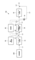
- FIG. 1 is a schematic configuration diagram showing an exhaust gas treatment device according to a first embodiment of the present disclosure.
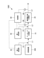
- the exhaust gas treatment device 100 of the present embodiment includes an ammonia decomposition section (first treatment section) 10, a nitrogen oxide decomposition section (second treatment section) 20, and an ammonia decomposition section (third treatment section). part) 30, a detection part 40, a first supply part 50 that supplies ammonia or urea water as a reducing agent, a temperature sensor 60, a bypass valve 70, and a control part 80.
- the exhaust gas discharged from the combustion device 200 is supplied to the ammonia decomposition unit 10 via the pipe L1.
- the exhaust gas that has passed through the ammonia decomposition section 10 is supplied to the nitrogen oxide decomposition section 20 via the pipe L2.
- the exhaust gas that has passed through the nitrogen oxide decomposition section 20 is supplied to the ammonia decomposition section 30 via the pipe L3.
- the exhaust gas that has passed through the ammonia decomposition section 30 is discharged to the outside via the pipe L4.
- the exhaust gas treatment device 100 of the present embodiment includes the pipe L5 and the bypass valve 70, it may be a modified example that does not include these. In this modification, the entire amount of exhaust gas that has passed through the nitrogen oxide decomposition section 20 is guided to the ammonia decomposition section 30.
- the ammonia decomposition unit 10 has an ammonia decomposition catalyst (first catalyst) that decomposes ammonia contained in the exhaust gas discharged from the combustion device 200.
- the ammonia decomposition catalyst is a multifunctional catalyst that not only decomposes ammonia but also decomposes NOx and suppresses the production of nitrous oxide.
- the ammonia decomposition catalyst of this embodiment includes a first component that is silica and/or zeolite supporting one or more noble metals selected from platinum (Pt), palladium (Pd), iridium (Ir), and rhodium (Rh). , a second component which is a composition comprising an oxide of one or more elements selected from titanium (Ti), tungsten (W) and vanadium (V). Examples of the ammonia decomposition catalyst will be described later.
- the ammonia decomposition catalyst of the ammonia decomposition unit 10 decomposes NH 3 using the first component according to the following formulas (1) and (2).
- ammonia decomposition catalyst of the ammonia decomposition unit 10 decomposes NH 3 using the second component according to the following formula (3), and also removes at least a portion of NO by-produced according to the formula (2).
- nitrous oxide N 2 O
- the ammonia decomposition catalyst since a small amount of noble metal catalyst is uniformly present on the denitrification catalyst, the NO2 generated on the precious metal catalyst is immediately converted to the NO2 generated on the denitration catalyst together with the NO generated in formula (2). There is a high probability that the reaction will result in N2 , and therefore the by-product of N2O can be reduced.
- 4NH 3 +7O 2 ⁇ 4NO 2 +6H 2 O 4NH 3 +4NO 2 +O 2 ⁇ 4N 2 O+6H 2 O (5) NO+NO 2 +2NH 3 ⁇ 2N 2 +3H 2 O (6)
- the nitrogen oxide decomposition unit 20 has a nitrogen oxide decomposition catalyst (second catalyst) that decomposes nitrous oxide and NOx contained in the exhaust gas from which ammonia has been decomposed in the ammonia decomposition unit 10.
- the nitrogen oxide decomposition catalyst contains a carrier containing SiO 2 and Al 2 O 3 and an iron element supported thereon. In the carrier, SiO 2 and Al 2 O 3 may be contained as a mixture or as a composite.
- An example of a composite of SiO2 and Al2O3 is aluminosilicate ( xM2O.yAl2O3.zSiO2.nH2O ) . Examples of the nitrogen oxide decomposition catalyst will be described later.
- the nitrogen oxide decomposition catalyst of the nitrogen oxide decomposition unit 20 decomposes nitrous oxide by subjecting it to a reduction reaction with NH 3 according to the following equation (7).
- the nitrogen oxide decomposition catalyst of the nitrogen oxide decomposition unit 20 decomposes NOx by subjecting it to a reduction reaction with NH 3 according to the following equations (8), (9), and (10).
- 4NO+4NH 3 +O 2 ⁇ 4N 2 +6H 2 O (8) NO+NO 2 +2NH 3 ⁇ 2N 2 +3H 2 O (9) 6NO 2 +8NH 3 ⁇ 7N 2 +12H 2 O (10)
- the ammonia decomposition unit 30 has an ammonia decomposition catalyst (third catalyst) that decomposes ammonia contained in the exhaust gas that has passed through the nitrogen oxide decomposition unit 20.
- the ammonia decomposition catalyst is a multifunctional catalyst that not only decomposes ammonia but also decomposes NOx and suppresses the production of nitrous oxide.
- the ammonia decomposition catalyst includes a first component that is silica and/or zeolite supporting one or more noble metals selected from platinum (Pt), palladium (Pd), iridium (Ir), and rhodium (Rh), and a titanium (Ti ), and a second component which is a composition comprising an oxide of one or more elements selected from tungsten (W) and vanadium (V).
- the configuration of the ammonia decomposition unit 30 is similar to the configuration of the ammonia decomposition unit 10, so the description below will be omitted.
- the detection unit 40 is a device that detects the concentration of nitrous oxide and NOx contained in the exhaust gas that has passed through the ammonia decomposition unit 10.
- the detection unit 40 detects the concentrations of nitrous oxide and NOx contained in the exhaust gas passing through the pipe L3.
- the concentrations of nitrous oxide and NOx detected by the detection unit 40 are transmitted to the control unit 80.
- the first supply unit 50 is a device that supplies ammonia or urea water, which is a reducing agent, to the exhaust gas supplied from the ammonia decomposition unit 10 to the nitrogen oxide decomposition unit 20.
- the first supply unit 50 supplies the reducing agent to the pipe L2 via the pipe L6, and mixes it with the exhaust gas flowing through the pipe L2.
- the pipe L6 mixes the reducing agent with the exhaust gas by, for example, spraying the reducing agent into the pipe L2.
- the first supply unit 50 adjusts the amount of reducing agent supplied to the pipe L2 according to a control signal transmitted from the control unit 80.
- the urea water mixed with the exhaust gas in the pipe L2 is hydrolyzed in the exhaust gas to generate ammonia.
- the nitrogen oxide decomposition catalyst of the nitrogen oxide decomposition unit 20 decomposes NOx by causing a reduction reaction with ammonia (NH 3 ) according to the above-mentioned equations (7), (8), and (9).
- the temperature sensor 60 is a device that detects the temperature of exhaust gas flowing through the pipe L2.
- the temperature sensor 60 transmits the detected temperature of the exhaust gas to the control unit 80.
- the bypass valve 70 is an on-off valve disposed in the pipe L5.
- the open/close state of the bypass valve 70 is controlled by a control section 80.
- the bypass valve 70 When the bypass valve 70 is in the open state, exhaust gas is guided from the pipe L3 to the pipe L4 via the pipe L5.
- the bypass valve 70 When the bypass valve 70 is in the closed state, the exhaust gas is not guided to the pipe L5, and the entire amount of exhaust gas flowing through the pipe L3 is guided to the pipe L4 via the ammonia decomposition section 30.
- the control unit 80 is a device that controls each part of the exhaust gas treatment device 100.
- the control unit 80 controls each unit of the exhaust gas treatment device 100 by reading and executing a control program stored in a storage unit (not shown).
- the control unit 80 controls the amount of reducing agent supplied to the pipe L2 by the first supply unit 50 according to the concentration of nitrous oxide and NOx detected by the detection unit 40 and the temperature of the exhaust gas detected by the temperature sensor 60. do. Further, the control unit 80 controls the opening/closing state of the bypass valve 70 according to the concentration of nitrous oxide and NOx detected by the detection unit 40 and the temperature of exhaust gas detected by the temperature sensor 60.
- FIG. 2 is a graph showing the decomposition characteristics of an ammonia decomposition catalyst. As shown in FIG. 2, as the temperature of the exhaust gas containing ammonia rises from 350°C to 450°C, the ammonia decomposition rate [%] by the ammonia decomposition catalyst of the ammonia decomposition unit 10 increases.
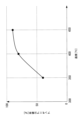
- FIG. 3 is a graph showing the relationship between ammonia concentration and temperature rise in an ammonia decomposition catalyst.
- the ammonia decomposition catalyst of the ammonia decomposition unit 10 increases the temperature of the exhaust gas as the concentration of unburned ammonia contained in the exhaust gas discharged from the combustion device 200 increases due to the heat generated when decomposing ammonia. The rise becomes larger.
- the temperature of the ammonia decomposition part 10 can be raised and the ammonia decomposition rate can be increased. Furthermore, the temperature of the exhaust gas discharged from the ammonia decomposition section 10 can be increased.
- FIG. 4 is a graph showing the decomposition characteristics of nitrous oxide with respect to the temperature of exhaust gas.
- Catalysts AF shown in FIG. 4 correspond to catalysts AF described in Examples of nitrogen oxide decomposition catalysts described later.
- the decomposition rate of nitrous oxide increases as the exhaust gas temperature increases. Therefore, when the ammonia decomposition catalyst of the ammonia decomposition unit 10 decomposes ammonia and raises the temperature of the exhaust gas, the decomposition rate of nitrous oxide increases as the temperature of the exhaust gas increases.
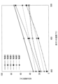
- FIG. 5 is a graph showing the NO decomposition characteristics with respect to exhaust gas temperature.
- Catalysts AF shown in FIG. 5 correspond to catalysts AF described in Examples of nitrogen oxide decomposition catalysts described later.
- the NO decomposition rate increases as the exhaust gas temperature increases. Therefore, when the ammonia decomposition catalyst of the ammonia decomposition unit 10 decomposes ammonia and raises the temperature of the exhaust gas, the NO decomposition rate increases as the temperature of the exhaust gas increases.
- the ammonia decomposition unit 10 is installed upstream of the nitrogen oxide decomposition unit 20 because the amount of unburned ammonia supplied in the exhaust gas discharged from the combustion device 200 is This is because it is assumed that the amount of ammonia exceeds the amount required for decomposing nitrous oxide and NOx in the decomposition unit 20.
- the exhaust gas treatment device 100 of this embodiment decomposes excess ammonia in the ammonia decomposition unit 10, increases the temperature of the exhaust gas by the heat generated when ammonia is decomposed, and reduces nitrous oxide and NOx in the nitrogen oxide decomposition unit 20. Increases decomposition rate.
- the exhaust gas treatment device 100 of this embodiment assumes that the concentrations of ammonia, nitrous oxide, and NOx contained in the exhaust gas discharged from the combustion device 200 satisfy the following equation (11). Ammonia concentration > ⁇ ⁇ nitrous oxide concentration + ⁇ ⁇ NOx concentration (11)
- the numerical values by which ⁇ and ⁇ are multiplied are not limited to 1.5, and may be set to any numerical value greater than or equal to 1.2 and less than or equal to 2.0, for example, depending on the properties of the exhaust gas from the combustion device 200.
- the reducing agent is supplied from the first supply section 50 to reduce ammonia in the nitrogen oxide decomposition section 20. Make up for the shortage.
- FIG. 6 is a flowchart showing the reducing agent supply process in the exhaust gas treatment apparatus 100 of this embodiment.
- the processing of each step in FIG. 6 is executed by the control section 80 controlling each section of the exhaust gas treatment apparatus 100.
- the process of this flowchart is started in response to the start of the combustion operation by the combustion device 200.
- step S101 the control unit 80 determines that the temperature Ta of the exhaust gas flowing through the pipe L2 transmitted from the temperature sensor 60 is equal to or higher than the supply temperature (for example, 350° C.) at which the reducing agent can be supplied to the nitrogen oxide decomposition unit 20. It is determined whether or not there is, and if YES, the process proceeds to step S102, and if NO, the process proceeds to step S108.
- the supply temperature for example, 350° C.
- step S108 the control unit 80 controls the first supply unit 50 to supply the reducing agent because the temperature Ta of the exhaust gas flowing through the pipe L2 is lower than the supply temperature at which the reducing agent can be supplied to the nitrogen oxide decomposition unit 20. control to stop.
- step S102 the control unit 80 determines whether the NOx concentration detected by the detection unit 40 is below a first predetermined concentration (for example, 200 ppm), and if YES, the process proceeds to step S103; If so, the process advances to step S105.
- a first predetermined concentration for example, 200 ppm
- step S103 the control unit 80 determines whether the nitrous oxide concentration detected by the detection unit 40 is equal to or lower than a second predetermined concentration (for example, 50 ppm), and if YES, the process proceeds to step S104, and if NO If so, the process advances to step S105.
- a second predetermined concentration for example, 50 ppm
- step S104 the control unit 80 determines that since the NOx concentration is the first predetermined concentration or less and the nitrous oxide concentration is the second predetermined concentration or less, the reduction process of NOx and nitrous oxide by ammonia is appropriately performed. It is determined that the supply amount of the reducing agent is reduced, and the first supply unit 50 is controlled to reduce the supply amount of the reducing agent.
- step S105 the control unit 80 determines that because the NOx concentration is higher than the first predetermined concentration or the nitrous oxide concentration is higher than the second predetermined concentration, the reduction process of NOx and nitrous oxide by ammonia is not sufficiently performed. It is determined that the first supply unit 50 is increased to increase the reducing agent supply amount, and the process proceeds to step S101.
- step S106 the control unit 80 determines whether the combustion device 200 is stopped, and if the determination is YES, the process proceeds to step S107, and if the determination is NO, the control unit 80 executes step S101 again.
- Combustion device 200 transmits operating states, including a state in which combustion operation is stopped, to control unit 80.
- step S107 the control unit 80 determines that the reduction treatment of NOx and nitrous oxide using ammonia is unnecessary because the combustion device 200 is stopped, and causes the first supply unit 50 to stop supplying the reducing agent. , the process of this flowchart ends. The control unit 80 restarts the process of this flowchart when the combustion device 200 starts the combustion operation.
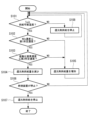
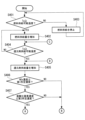
- FIG. 7 is a flowchart showing switching processing of the bypass valve 70 in the exhaust gas treatment device 100 of this embodiment.
- the processing of each step in FIG. 7 is executed by the control section 80 controlling each section of the exhaust gas treatment apparatus 100.
- the process of this flowchart is started in response to the start of the combustion operation by the combustion device 200.
- the exhaust gas treatment device 100 of this embodiment has an ammonia decomposition unit 30 disposed downstream of the nitrogen oxide decomposition unit 20.
- the ammonia decomposition unit 30 is configured to remove surplus This is provided to ensure that the ammonia is decomposed and not discharged to the outside.
- the ammonia decomposition unit 30 does not need to process the exhaust gas in the ammonia decomposition unit 30, When the exhaust gas passes through the ammonia decomposition section 30, a pressure loss is caused. Therefore, in this embodiment, when the concentration of ammonia contained in the exhaust gas discharged from the nitrogen oxide decomposition unit 20 is below a predetermined permissible concentration, a part of the exhaust gas discharged from the nitrogen oxide decomposition unit 20 is By guiding the exhaust gas to the pipe L5, pressure loss is prevented from occurring when the exhaust gas passes through the ammonia decomposition section 30.
- step S201 the control unit 80 determines that the temperature Ta of the exhaust gas flowing through the pipe L2 transmitted from the temperature sensor 60 is equal to or higher than the supply temperature (for example, 350° C.) at which the reducing agent can be supplied to the nitrogen oxide decomposition unit 20. It is determined whether or not there is, and if YES, the process proceeds to step S203, and if NO, the process proceeds to step S202.
- the supply temperature for example, 350° C.
- step S202 the control unit 80 determines that the temperature Ta of the exhaust gas flowing through the pipe L2 is lower than the supply temperature at which the reducing agent can be supplied to the nitrogen oxide decomposition unit 20, and the temperature of the exhaust gas discharged from the combustion device 200 is Since the temperature has not risen to an appropriate level, the bypass valve 70 is controlled to be closed.
- step S203 the control unit 80 determines whether the load of the combustion device 200 is below a predetermined load (for example, 50% load), and if the determination is YES, the process proceeds to step S204, and if the determination is NO. If so, step S201 is executed again.
- Combustion device 200 transmits the load of combustion operation to control unit 80 .
- step S204 the control unit 80 controls the bypass valve 70 to open because the load on the combustion device 200 is less than or equal to the predetermined load.
- the concentration of ammonia contained in the exhaust gas discharged from the nitrogen oxide decomposition unit 20 is below a predetermined permissible concentration (for example, 5 ppm), and the exhaust gas is removed by the ammonia decomposition unit 30. No need to process. Therefore, in order to reduce the pressure loss caused when the exhaust gas passes through the ammonia decomposition section 30, a part of the exhaust gas flowing through the pipe L3 is guided from the pipe L5 to the pipe L4.
- step S205 the control unit 80 determines whether the combustion device 200 is stopped, and if the determination is YES, the process proceeds to step S206, and if the determination is NO, the control unit 80 executes step S201 again.
- Combustion device 200 transmits operating states, including a state in which combustion operation is stopped, to control unit 80.
- step S206 since the combustion device 200 is stopped, the control unit 80 closes the bypass valve 70 and ends the process of this flowchart. The control unit 80 restarts the process of this flowchart when the combustion device 200 starts the combustion operation.
- the detection unit 40 detects the concentrations of nitrous oxide and NOx contained in the exhaust gas that has passed through the ammonia decomposition unit 10, but other embodiments may be used.
- the detection unit 40 may detect the concentration of either nitrous oxide or NOx contained in the exhaust gas that has passed through the ammonia decomposition unit 10.
- the detection unit 40 detects the concentration of nitrous oxide
- the process of step S102 in FIG. 6 is omitted.
- the detection unit 40 detects the concentration of NOx
- the process of step S103 in FIG. 6 is omitted.
- ammonia decomposition catalyst of the ammonia decomposition unit 10 of this embodiment can be obtained, for example, by any of the following examples.
- Example 1 100 g of fine silica powder (manufactured by Tomita Pharmaceutical Co., Ltd., silicic anhydride) was added to 1 liter of 1.33 ⁇ 10 -2 wt% chloroplatinic acid (H 2 [PtCl 6 ].6H 2 O) aqueous solution, and the mixture was poured on a sand bath. The mixture was evaporated to dryness and calcined in air at 500° C. for 2 hours to prepare 0.05 wt% Pt.SiO 2 to obtain a catalyst composition powder as the first component.
- chloroplatinic acid H 2 [PtCl 6 ].6H 2 O
- ammonium paratungstate (NH 4 ) 10.W 12 O 41.5H 2 O) 7 .
- 43 kg of ammonium metavanadate and 3.0 kg of ammonium metavanadate were added and kneaded using a kneader, and the resulting paste was granulated, dried, and fired at 550° C. for 2 hours.
- the obtained granules were crushed to obtain catalyst composition powder as the second component.
- a slurry obtained by suspending 20 g of the first component and 2.02 kg of the second component in 3.06 kg of water is coated with a paper honeycomb carrier (manufactured by Nichias Corporation, trade name, Honeycle 3722, 150 mm x 150 mm square, length 50 mm). After the carrier was impregnated with the slurry by immersion, the liquid was removed by air blowing to obtain the catalyst of this example. This was air-dried in the atmosphere for 12 hours and then fired at 500°C for 2 hours.
- the first component/second component ratio of the first component and the second component in this catalyst is 1/99 (weight ratio, same hereinafter), the Pt content in the catalyst component is equivalent to 5 ppm, and the catalyst is supported.
- the amount of the first and second components together was 150 g/m 2 per carrier surface area.
- a test piece with a length of 50 mm and a size of 5 stages x 8 cells (11 x 14 mm) was cut out from the obtained honeycomb catalyst.
- Example 2 A catalyst of this example was obtained in the same manner as in Example 1 except that the first component was changed to 10 g, the second component was changed to 2.02 kg, and the water was changed to 3.04 kg.
- the first component/second component ratio of the first component and the second component in this catalyst is 0.5/99.5, the Pt content in the catalyst component is equivalent to 2.5 ppm, and the supported amount of the catalyst is
- the total amount of the first and second components was 150 g/m 2 per carrier surface area.
- Example 3-5 Using the first component and second component obtained in Example 1, the amount of water added during slurry preparation was changed to 476 and 816 kg, and the resulting slurry was transferred to a paper honeycomb carrier (manufactured by Nichias Co., Ltd., trade name, Honeycle 3319, The catalyst of this example was obtained by supporting the catalyst on a 150 mm x 150 mm square and 50 mm length in the same manner as in Example 1. The first component/second component ratio of the first component and the second component in this catalyst was 1/99, and the Pt content in the catalyst component was equivalent to 5 ppm. The supported amounts of the catalyst in Example 3-5 were 100, 80, and 50 g/m 2 per carrier surface area, including the first component and the second component, respectively.
- Example 6 A catalyst of this example was obtained in the same manner as in Example 1 except that the paper honeycomb carrier of Example 1 was changed to a metal lath (SUS304, plate thickness 0.2 mm, 150 mm x 150 mm square). The first component/second component ratio of the first component and the second component in this catalyst was 1/99, and the Pt content in the catalyst component was equivalent to 5 ppm. The amount of catalyst supported was 200 g/m 2 per surface area of the carrier, including the first component and the second component.
- a metal lath SUS304, plate thickness 0.2 mm, 150 mm x 150 mm square
- the nitrogen oxide decomposition catalyst of the nitrogen oxide decomposition unit 20 of this embodiment is, for example, any of the following catalysts A to E.
- iron (III) nitrate nonahydrate Fe 2 (NO 3 ) 3.9H 2 O
- This powder was added to 2000 ml of an aqueous solution containing 13.2 g of iron(III) nitrate nonahydrate (Fe 2 (NO 3 ) 3.9H 2 O), and the above operation was repeated two more times (3 ion exchange steps in total). ) to obtain powdered Fe-supported zeolite catalyst D.
- Honeycomb catalyst D was obtained by the same manufacturing method as catalyst A except that Fe-supported zeolite catalyst A was replaced with Fe-supported zeolite catalyst D.
- the exhaust gas treatment device 100 According to the exhaust gas treatment device 100 according to the present disclosure, ammonia contained in the exhaust gas discharged from the combustion device 200 is appropriately decomposed by the ammonia decomposition catalyst when passing through the ammonia decomposition section 10. Further, nitrous oxide and NOx generated when ammonia is burned in the combustion device 200 are appropriately decomposed by the nitrogen oxide decomposition catalyst when passing through the nitrogen oxide decomposition section 20. In this manner, the exhaust gas treatment device 100 according to the present disclosure can appropriately decompose ammonia and nitrous oxide contained in the exhaust gas discharged from the combustion device 200 that burns fuel containing ammonia.
- the exhaust gas treatment device 100 of the present embodiment even if ammonia remains in the exhaust gas that has passed through the nitrogen oxide decomposition unit 20, the ammonia is decomposed in the ammonia decomposition unit 30, so that ammonia is removed from the outside. can be prevented from being discharged.
- the concentration of nitrous oxide contained in the exhaust gas that has passed through the nitrogen oxide decomposition section 20 is higher than the first predetermined concentration, or the concentration of nitrous oxide contained in the exhaust gas that has passed through the nitrogen oxide decomposition section 20 is
- the detection unit 40 detects that the concentration of NOx contained is higher than the second predetermined concentration
- the NOx is supplied to the nitrogen oxide decomposition unit 20 to compensate for the lack of ammonia for reducing nitrous oxide and NOx.
- a reducing agent is supplied to the exhaust gas from the first supply section 50.
- the shortage of ammonia supplied from the ammonia decomposition unit 10 to the nitrogen oxide decomposition unit 20 is compensated for, and the concentration of nitrous oxide and NOx contained in the exhaust gas that has passed through the nitrogen oxide decomposition unit 20 is reduced. Can be done.
- the exhaust gas treatment device 100A of the present embodiment is a modification of the exhaust gas treatment device 100 of the first embodiment, and is the same as the first embodiment except when specifically explained below. Omitted.
- the exhaust gas treatment device 100B of the present embodiment is different from the first embodiment in that it includes a pipe (bypass pipe) L7 that guides a part of the exhaust gas flowing through the pipe L1 to the pipe L2, and a bypass valve 90 disposed in the pipe L7. This is different from the exhaust gas treatment device 100.
- FIG. 8 is a schematic configuration diagram showing an exhaust gas treatment device 100A according to the second embodiment of the present disclosure.
- the exhaust gas treatment device 100A of this embodiment includes a pipe L7 that guides a part of the exhaust gas flowing through the pipe L1 to the pipe L2, and a bypass valve 90 arranged in the pipe L7.
- the bypass valve 90 is an on-off valve arranged in the pipe L7.
- the opening/closing state of the bypass valve 90 is controlled by the control section 80.
- the bypass valve 90 When the bypass valve 90 is in the open state, exhaust gas is guided from the pipe L1 to the pipe L2 via the pipe L7.
- the bypass valve 90 When the bypass valve 90 is in the closed state, the exhaust gas is not guided to the pipe L7, and the entire amount of exhaust gas flowing through the pipe L1 is guided to the pipe L2 via the ammonia decomposition unit 10.
- the supply amount of unburned ammonia contained in the exhaust gas discharged from the combustion device 200 is the amount of ammonia necessary for decomposing nitrous oxide and NOx in the nitrogen oxide decomposition unit 20. If the amount exceeds , the bypass valve 90 is closed, the entire amount of exhaust gas flowing through the pipe L1 is guided to the ammonia decomposition section 10, and the excess ammonia is decomposed in the ammonia decomposition section 10.
- the supply amount of unburned ammonia contained in the exhaust gas discharged from the combustion device 200 is necessary for decomposing nitrous oxide and NOx in the nitrogen oxide decomposition unit 20.
- the bypass valve 90 is opened and a part of the exhaust gas flowing through the pipe L1 is guided to the pipe L2 without passing through the ammonia decomposition section 10.
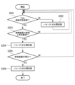
- FIG. 9 is a flowchart showing switching processing of the bypass valve 90 of the exhaust gas treatment device 100A according to the present embodiment.
- the processing of each step in FIG. 9 is executed by the control unit 80 controlling each part of the exhaust gas treatment apparatus 100A.
- the process of this flowchart is started in response to the start of the combustion operation by the combustion device 200.
- step S301 the control unit 80 determines that the temperature Ta of the exhaust gas flowing through the pipe L2, which is transmitted from the temperature sensor 60, is equal to or higher than the supply temperature (for example, 350° C.) at which the reducing agent can be supplied to the nitrogen oxide decomposition unit 20. It is determined whether or not there is, and if YES, the process proceeds to step S302, and if NO, the process proceeds to step S305.
- the supply temperature for example, 350° C.
- step S302 the control unit 80 calculates the concentration of each component of ammonia, nitrous oxide, and NOx in the exhaust gas discharged from the combustion device 200 based on the load of the combustion device 200.
- Combustion device 200 transmits the load of combustion operation to control unit 80 .
- the control unit 80 stores in a storage unit (not shown) a map of the concentration of each component of ammonia, nitrous oxide, and NOx, which is associated with each of the plurality of loads of the combustion device 200.
- the control unit 80 calculates the concentration associated with the load transmitted from the combustion device 200 with reference to the map stored in the storage unit.
- step S303 the control unit 80 determines whether the ammonia concentration calculated in step S302 is below a predetermined concentration, and if YES, the process proceeds to step S304, and if NO, the process proceeds to step S305.
- the predetermined concentration is the concentration expressed by the following equation (12).
- step S304 the control unit 80 controls the bypass valve 90 because the ammonia concentration is below the predetermined concentration and there is no need to supply the entire amount of exhaust gas to the ammonia decomposition unit 10 in order to decompose excess ammonia in the ammonia decomposition unit 10. Open.
- step S305 the control unit 80 closes the bypass valve 90 because the exhaust gas temperature Ta is lower than the supply temperature at which the reducing agent can be supplied to the nitrogen oxide decomposition unit 20, or the ammonia concentration is higher than the predetermined concentration. state. This is because the temperature of the exhaust gas discharged from the combustion device 200 is not high enough, or the ammonia concentration contained in the exhaust gas is higher than the predetermined concentration, so it is necessary to supply the entire amount of the exhaust gas to the ammonia decomposition unit 10. It is.
- step S306 the control unit 80 determines whether the combustion device 200 is stopped, and if the determination is YES, the process proceeds to step S307, and if the determination is NO, the control unit 80 executes step S301 again.
- Combustion device 200 transmits operating states, including a state in which combustion operation is stopped, to control unit 80.
- step S307 since the combustion device 200 is stopped, the control unit 80 closes the bypass valve 90, and ends the process of this flowchart. The control unit 80 restarts the process of this flowchart when the combustion device 200 starts the combustion operation.
- the concentration of ammonia contained in the exhaust gas discharged from the combustion device 200 is the concentration required as a reducing agent when decomposing nitrous oxide and NOx in the nitrogen oxide decomposition unit 20. If the value is higher than , excess ammonia can be decomposed by the ammonia decomposition unit 10 by closing the bypass valve 90 .
- the concentration of ammonia contained in the exhaust gas discharged from the combustion device 200 is the same as or lower than the concentration required as a reducing agent when decomposing nitrous oxide and NOx in the nitrogen oxide decomposition unit 20, By opening the bypass valve 90, ammonia can be guided to the nitrogen oxide decomposition unit 20 without being decomposed in the ammonia decomposition unit 10.
- the exhaust gas treatment device 100B of the present embodiment is a modification of the exhaust gas treatment device 100 of the first embodiment, and is the same as the first embodiment except when specifically explained below. Omitted.
- the exhaust gas treatment device 100 of the first embodiment had the ammonia decomposition unit 10 disposed upstream of the nitrogen oxide decomposition unit 20.
- the exhaust gas treatment device 100B of this embodiment does not include the ammonia decomposition unit 10 upstream of the nitrogen oxide decomposition unit 20.
- FIG. 10 is a schematic configuration diagram showing an exhaust gas treatment device 100B according to a third embodiment of the present disclosure.
- the exhaust gas treatment device 100B of this embodiment does not include the ammonia decomposition unit 10 upstream of the nitrogen oxide decomposition unit 20, and the exhaust gas discharged from the combustion device 200 is The nitrogen oxides are supplied to the nitrogen oxide decomposition unit 20 via the nitrogen oxide decomposition unit 20.
- the ammonia decomposition unit 10 is not installed upstream of the nitrogen oxide decomposition unit 20 because the amount of unburned ammonia supplied in the exhaust gas discharged from the combustion device 200 is This is because it is assumed that the amount of ammonia required to decompose nitrous oxide and NOx in the decomposition unit 20 is equal to or less than that.
- the exhaust gas treatment device 100B of this embodiment makes up for the shortage of ammonia necessary as a reducing agent for decomposing nitrous oxide and NOx contained in the exhaust gas by supplying it from the first supply unit 50.
- the exhaust gas treatment device 100B of this embodiment assumes that the concentrations of ammonia, nitrous oxide, and NOx contained in the exhaust gas discharged from the combustion device 200 satisfy the following equation (13).
- ⁇ and ⁇ are coefficients, which are the same as those explained in equation (11) of the first embodiment.
- the reducing agent supply process in the exhaust gas treatment device 100B of this embodiment is similar to the process shown in FIG. 6 of the first embodiment.
- the switching process of the bypass valve 70 in the exhaust gas treatment apparatus 100A of this embodiment is similar to the process shown in FIG. 7 of the first embodiment.
- the exhaust gas treatment device 100B of this embodiment The functions and effects of the exhaust gas treatment device 100B of this embodiment described above will be explained.
- ammonia contained in the exhaust gas discharged from the combustion device 200 is converted into nitrous oxide and nitrous oxide as a reducing agent by the nitrogen oxide decomposition catalyst when passing through the nitrogen oxide decomposition unit 20. Decomposed by reacting with NOx. Further, nitrous oxide and NOx generated when ammonia is burned in the combustion device 200 are appropriately decomposed by the nitrogen oxide decomposition catalyst when passing through the nitrogen oxide decomposition section 20.
- the exhaust gas treatment device 100B of the present embodiment can appropriately decompose ammonia, nitrous oxide, and NOx contained in the exhaust gas discharged from the combustion device 200 that burns fuel containing ammonia.
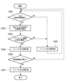
- the design method of this embodiment includes a design in which the ammonia decomposition unit 10 is disposed upstream of the nitrogen oxide decomposition unit 20 as in the exhaust gas treatment apparatuses 100 and 100A described in the first embodiment and the second embodiment, and This is a method of determining which design to perform, a design in which the ammonia decomposition unit 10 is not disposed on the upstream side of the nitrogen oxide decomposition unit 20, like the exhaust gas treatment device 100B described in the third embodiment.
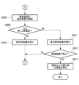
- FIG. 11 is a flowchart showing a method for designing an exhaust gas treatment device according to this embodiment.
- step S401 the concentration of each component of ammonia, nitrous oxide, and NOx in the exhaust gas discharged from the combustion device 200 is calculated.
- the concentration of each component is determined by assuming that the combustion device 200 operates at a predetermined constant load, and specifying the concentration of each component of ammonia, nitrous oxide, and NOx in the exhaust gas at that load.
- step S402 it is determined whether the ammonia concentration calculated in step S401 is below a predetermined concentration, and if YES, the process proceeds to step S403, and if NO, the process proceeds to step S404.
- the predetermined concentration is the concentration expressed by equation (12) of the second embodiment, which is ⁇ nitrous oxide concentration+ ⁇ NOx concentration.
- step S403 since the ammonia concentration in the exhaust gas discharged from the combustion device 200 is below the predetermined concentration, the exhaust gas treatment device 100B of the third embodiment does not dispose the ammonia decomposition unit 10 upstream of the nitrogen oxide decomposition unit 20.
- the design shall be as follows. The reason for this design is that there is no need to dispose the ammonia decomposition section 10 upstream of the nitrogen oxide decomposition section 20 to decompose excess ammonia.
- step S404 since the ammonia concentration in the exhaust gas discharged from the combustion device 200 is higher than the predetermined concentration, the exhaust gas treatment device 100 of the first embodiment or This is a design of an exhaust gas treatment device 100A of the second embodiment.
- the reason for this design is that since the ammonia concentration contained in the exhaust gas is higher than a predetermined concentration, it is necessary to supply the entire amount of the exhaust gas to the ammonia decomposition unit 10 to decompose excess ammonia.
- the concentration of ammonia contained in the exhaust gas is equal to the first concentration obtained by multiplying the concentration of nitrous oxide contained in the exhaust gas by ⁇ (first coefficient). If the concentration of ammonia supplied from the ammonia decomposition unit 10 to the nitrogen oxide decomposition unit 20 is higher than the total concentration of the second concentration obtained by multiplying the NOx concentration by ⁇ (second coefficient), the concentration of ammonia supplied from the ammonia decomposition unit 10 to the nitrogen oxide decomposition unit 20 becomes excessive.
- the exhaust gas treatment device is designed so that the ammonia decomposition section 10 is disposed downstream of the combustion device 200, and the nitrogen oxide decomposition section 20 is disposed downstream of the ammonia decomposition section 10.
- the concentration of ammonia contained in the exhaust gas is calculated by multiplying the concentration of nitrous oxide contained in the exhaust gas by ⁇ (first coefficient), and the concentration of NOx contained in the exhaust gas multiplied by ⁇ (second coefficient). If the concentration is lower than the total concentration with the second concentration, the concentration of ammonia supplied from the ammonia decomposition unit 10 to the nitrogen oxide decomposition unit 20 will not become excessive.
- the exhaust gas treatment device is designed so that the nitrogen oxide decomposition section 20 is arranged without the nitrogen oxide decomposition section 10. Thereby, it is possible to design an exhaust gas treatment device having an appropriate configuration according to the concentration of ammonia contained in the exhaust gas discharged from the combustion device 200.
- the exhaust gas treatment device 100C of the present embodiment is a modification of the exhaust gas treatment device 100 of the first embodiment, and is the same as the first embodiment except when specifically explained below. Omitted.
- the exhaust gas treatment device 100C of this embodiment uses ammonia or urea water as a fuel for heating the ammonia decomposition catalyst (first treatment section) of the ammonia decomposition section 10 in the exhaust gas supplied from the combustion device 200 to the ammonia decomposition section 10. This differs from the exhaust gas treatment device 100 of the first embodiment in that it includes a second supply section 55 that supplies . Further, the exhaust gas treatment device 100C of this embodiment differs from the exhaust gas treatment device 100 of the first embodiment in that it does not include the ammonia decomposition unit 30.
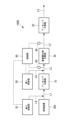
- FIG. 12 is a schematic configuration diagram showing an exhaust gas treatment device 100C according to the present embodiment.
- the exhaust gas treatment device 100C of this embodiment includes an ammonia decomposition unit (first treatment unit) 10, a nitrogen oxide decomposition unit (second treatment unit) 20, a detection unit 40, and a first It includes a supply section 50, a second supply section 55, a temperature sensor 60, and a control section 80.
- the other configurations except for the second supply section 55 are the same as those in the first embodiment, so the description below will be omitted.
- the second supply unit 55 supplies ammonia or This is a device that supplies urea water.
- the second supply unit 55 supplies urea water to the pipe L1 via the pipe L8, and generates ammonia through a hydrolysis reaction of the urea water.
- Ammonia guided to the ammonia decomposition unit 10 is decomposed by the action of the ammonia decomposition catalyst according to the reactions of formulas (1) and (2) of the first embodiment. Due to the exothermic reaction when ammonia is decomposed, the exhaust gas passing through the ammonia decomposition section 10 is heated. Furthermore, instead of supplying urea water from the second supply section 55, ammonia may be supplied from the second supply section 55 to the pipe L2.
- the inventors conducted an experiment to confirm the relationship between the properties of the exhaust gas discharged from the combustion device 200 and the decomposition rate of nitrous oxide, and found that the decomposition rate of nitrous oxide changes depending on the concentration of NO contained in the exhaust gas. We obtained the knowledge that there is a temperature range where this occurs. If the decomposition rate of nitrous oxide changes depending on the concentration of NO contained in the exhaust gas, there is a possibility that the desired decomposition rate of nitrous oxide cannot be obtained in the exhaust gas treatment device 100 of the first embodiment. Therefore, in the exhaust gas treatment apparatus 100C of this embodiment, the nitrogen oxide decomposition unit 20 is operated in a temperature range in which the decomposition rate of nitrous oxide does not change depending on the concentration of NO contained in the exhaust gas.
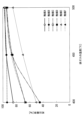
- FIG. 13 is a graph showing the decomposition rate of nitrous oxide with respect to the temperature of the exhaust gas in the nitrogen oxide decomposition unit 20, comparing the cases where the NO concentration is 0 ppm and the case where it is 450 ppm.
- FIG. 13 shows an example in which catalyst A is used as the nitrogen oxide decomposition catalyst in the nitrogen oxide decomposition section 20.
- the example shown by the solid line and the example shown by the dotted line in FIG. 13 differ in that the NO concentration in the exhaust gas is 450 ppm and 0 ppm.
- the nitrous oxide concentration in the exhaust gas is 180 ppm
- the ammonia concentration in the exhaust gas is 570 ppm
- the oxygen concentration in the exhaust gas is 13%. They have in common that the sulfur dioxide concentration in the exhaust gas is 15 ppm, the moisture concentration in the exhaust gas is 15%, and the remainder is nitrogen.
- FIG. 13 shows the above-mentioned tendency is that the oxygen bound to the nitrogen oxide decomposition catalyst in the following formula (11) is lower than 450°C, while the oxygen bound to the nitrogen oxide decomposition catalyst in formula (12) is This is presumed to be because nitrous oxide was removed and/or reduced by the reaction of formula (13). That is, it is presumed that this is because the decomposition rate of nitrous oxide becomes higher when NO in the exhaust gas exists together with nitrous oxide.
- the inventors set the temperature of the exhaust gas discharged from the ammonia decomposition unit 10 so that the decomposition rate of nitrous oxide would not change depending on the concentration of NO contained in the exhaust gas.
- the temperature range was set so that the temperature was 450°C or higher. Further, the inventors set a temperature range such that the temperature of the exhaust gas discharged from the ammonia decomposition unit 10 is 530° C. or lower in order to reduce thermal stress on the catalytic reactor and suppress thermal deterioration of the catalyst.
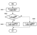
- 14 to 16 are flowcharts showing fuel and reducing agent supply processing in the exhaust gas treatment device 100C according to the present embodiment.
- the processing of each step in FIGS. 14 to 16 is executed by the control unit 80 controlling each part of the exhaust gas treatment apparatus 100C.
- the process of this flowchart is started in response to the start of the combustion operation by the combustion device 200.
- step S401 the control unit 80 determines that the temperature Ta of the exhaust gas flowing through the pipe L2 transmitted from the temperature sensor 60 is such that the fuel for heating the ammonia decomposition catalyst (first processing unit) is replaced with ammonia from the second supply unit 55. It is determined whether the temperature is higher than the temperature at which fuel can be supplied to the decomposition unit 10 (for example, 300° C.), and if YES, the process proceeds to step S402, and if NO, the process proceeds to step S403.
- step S402 the control unit 80 controls the second supply unit 55 to increase the amount of fuel supplied from the second supply unit 55 to the pipe L1.
- step S402 is executed for the first time after step S401, the amount of fuel supplied by the second supply section 55 is increased from 0 to a predetermined amount of supply.
- step S403 the control unit 80 stops the second supply unit 55 from supplying fuel because the temperature Ta of the exhaust gas flowing through the pipe L1 is lower than the temperature at which fuel can be supplied to the ammonia decomposition unit 10. control like this.
- step S404 the control unit 80 determines whether the temperature Ta of the exhaust gas is equal to or higher than the reducing agent supply temperature (for example, 450° C.) at which the reducing agent can be supplied to the nitrogen oxide decomposition unit 20, and if YES is determined. If the answer is NO, the process advances to step S402 and the amount of fuel supplied from the second supply section 55 is increased.
- the reducing agent supply temperature for example, 450° C.
- step S405 the control unit 80 controls the first supply unit 50 to increase the amount of reducing agent supplied from the first supply unit 50 to the pipe L2.
- step S405 is executed for the first time after step S404, the amount of reducing agent supplied by the first supply unit 50 is increased from 0 to a predetermined amount of supply.
- step S406 the control unit 80 determines whether the NOx concentration detected by the detection unit 40 is equal to or lower than a first predetermined concentration (for example, 200 ppm), and if YES, the process proceeds to step S407; If so, the process advances to step S414.
- a first predetermined concentration for example, 200 ppm
- step S407 the control unit 80 determines whether the nitrous oxide concentration detected by the detection unit 40 is equal to or lower than a second predetermined concentration (for example, 10 ppm), and if YES, the process proceeds to step S408, and if NO If so, the process advances to step S414.
- a second predetermined concentration for example, 10 ppm
- step S408 the control unit 80 controls the combustion device 200 to release the load restriction on the combustion device 200.
- the control unit 80 controls the combustion device 200 to have a predetermined load or less until the load restriction is canceled in this step. This is because the reducing agent supplied from the first supply section 50 to the nitrogen oxide decomposition section 20 is reduced in order to reduce the NOx concentration and the nitrous oxide concentration when the combustion device 200 is operated without limiting the load. This is because if the supply amount becomes excessive, unreacted ammonia may be discharged from the nitrogen oxide decomposition unit 20 to the outside via the pipe L3.
- unreacted ammonia is discharged from the nitrogen oxide decomposition unit 20 to the outside via the pipe L3 by controlling the combustion device 200 so that the load is below a predetermined value.
- the NOx concentration and nitrous oxide concentration can be made below the threshold value, and the environmental load can be reduced.
- step S409 the control unit 80 determines whether the temperature Ta is lower than or equal to the first upper limit temperature (for example, 480° C.), and if YES, the process proceeds to step S410, and if NO, the process proceeds to step S411. proceed.
- the first upper limit temperature for example, 480° C.
- step S410 the control unit 80 reduces the amount of fuel supplied from the second supply unit 55 to the pipe L1 so that the temperature Ta is below the first upper limit temperature. After executing step S410, the control unit 80 advances the process to step S404.
- step S411 since the temperature Ta is lower than the first upper limit temperature, the control unit 80 reduces the amount of reducing agent supplied from the first supply unit 50 to the pipe L2 and advances the process to step S412.
- step S412 the control unit 80 determines whether the combustion device 200 is stopped, and if the determination is YES, the process proceeds to step S413, and if the determination is NO, the control unit 80 executes step S404 again.
- Combustion device 200 transmits operating states, including a state in which combustion operation is stopped, to control unit 80.
- step S413 since the combustion device 200 is stopped, the control unit 80 stops the supply of reducing agent by the first supply unit 50 and the supply of fuel by the second supply unit 55, and ends the process of this flowchart. do.
- the control unit 80 restarts the process of this flowchart when the combustion device 200 starts the combustion operation.
- step S414 the control unit 80 calculates the amount of reducing agent required to reduce NOx and nitrous oxide based on the NOx concentration and nitrous oxide concentration calculated in step S302 of FIG. It is determined whether the amount of reducing agent being supplied is greater than the amount obtained by multiplying the required amount of reducing agent by a predetermined coefficient ⁇ , and if YES, the process proceeds to step S415, and if NO, the process proceeds to step S405. Proceed.
- the predetermined reducing agent supply amount is the supply amount obtained by multiplying the reducing agent amount necessary to reduce NOx and nitrous oxide included in the total nitrogen oxide concentration by a predetermined coefficient ⁇ .
- the coefficient ⁇ is set, for example, to a value of 0.8 or more and 1.2 or less.
- step S415 the control unit 80 determines whether the temperature Ta is equal to or lower than the second upper limit temperature (for example, 530° C.), and if YES, the process proceeds to step S416, and if NO, the process proceeds to step S417. proceed.
- the second upper limit temperature for example, 530° C.
- step S416 the control unit 80 increases the amount of fuel supplied from the second supply unit 55 to the pipe L1. After executing step S416, the control unit 80 advances the process to step S419.
- step S417 the control unit 80 reduces the amount of fuel supplied from the second supply unit 55 to the pipe L1 so that the temperature Ta becomes lower than the second upper limit temperature.
- step S4108 the control unit 80 reduces the output of the combustion device 200 (for example, reduces the load by 10%), and advances the process to step S404.
- step S419 the control unit 80 determines whether the combustion device 200 is stopped, and if the determination is YES, the process proceeds to step S420, and if the determination is NO, the control unit 80 executes step S405 again.
- Combustion device 200 transmits operating states, including a state in which combustion operation is stopped, to control unit 80.
- step S420 since the combustion device 200 is stopped, the control unit 80 stops the supply of reducing agent by the first supply unit 50 and the supply of fuel by the second supply unit 55, and ends the processing of this flowchart. do.
- the control unit 80 restarts the process of this flowchart when the combustion device 200 starts the combustion operation.
- the exhaust gas treatment device 100C of this embodiment by supplying ammonia or urea water to the exhaust gas supplied from the combustion device 200 to the ammonia decomposition unit 10, the exothermic reaction by oxidation of ammonia in the ammonia decomposition unit 10 is promoted. can be done. As a result, the temperature of the exhaust gas led from the ammonia decomposition unit 10 to the nitrogen oxide decomposition unit 20 is appropriately raised, and nitrogen oxide is oxidized within a temperature range where the decomposition rate of nitrous oxide does not change depending on the concentration of NO contained in the exhaust gas.
- the material decomposition section 20 can be operated.
- the decomposition rate of nitrous oxide does not change depending on the concentration of NO contained in the exhaust gas.
- the nitrogen oxide decomposition section 20 can be operated in a temperature range that is within a certain temperature range.
- the exhaust gas treatment device 100C of this embodiment discharges the exhaust gas that has passed through the nitrogen oxide decomposition unit 20 to the outside via the pipe L3, other embodiments may be used.
- the exhaust gas treatment device 100D shown in FIG. It may also be discharged to the outside.
- FIG. 17 is a schematic configuration diagram showing an exhaust gas treatment device 100D according to a modification of the fifth embodiment of the present disclosure.
- the ammonia decomposition unit 30 shown in FIG. 17 has the same configuration as the ammonia decomposition unit 30 of the first embodiment. According to the exhaust gas treatment device 100D shown in FIG. 17, even if the exhaust gas that has passed through the nitrogen oxide decomposition unit 20 contains ammonia, the ammonia is appropriately decomposed in the ammonia decomposition unit 30 and the ammonia is not discharged to the outside. You can do it like this.
- step S414 the NOx and nitrous oxide concentrations calculated in step S302 of FIG.
- the amount of reducing agent required to reduce nitrogen is calculated, and the coefficient ⁇ by which the required amount of reducing agent is multiplied is set to a larger value (for example, 1.5) than in the fifth embodiment.
- An exhaust gas treatment device (100) is an exhaust gas treatment device (100, 100A) that processes exhaust gas discharged from a combustion device (200) that burns fuel containing ammonia, and includes ammonia contained in the exhaust gas. a first treatment section (10) having a first catalyst that decomposes ammonia; and a second treatment section (10) having a second catalyst that decomposes nitrous oxide and NOx contained in the exhaust gas from which ammonia has been decomposed in the first treatment section. (20) and.
- ammonia contained in the exhaust gas discharged from the combustion device is appropriately decomposed by the first catalyst when passing through the first treatment section. Furthermore, nitrous oxide and NOx generated when ammonia is burned in the combustion device are appropriately decomposed by the second catalyst when passing through the second treatment section. In this manner, the exhaust gas treatment device according to the present disclosure can appropriately decompose ammonia, nitrous oxide, and NOx contained in the exhaust gas discharged from a combustion device that burns fuel containing ammonia.
- the first treatment section may be configured to use the first catalyst to remove NOx generated when decomposing ammonia contained in the exhaust gas. According to the exhaust gas treatment device having this configuration, since NOx generated when decomposing ammonia in the first treatment section is removed by the first catalyst, NOx contained in the exhaust gas discharged from the combustion device is removed from the first treatment. This can be appropriately prevented from increasing when passing through the area.
- a bypass pipe (L7) that guides the exhaust gas discharged from the combustion device to the second processing unit without passing through the first processing unit;
- a configuration including a bypass valve (90) may also be provided.
- the exhaust gas treatment device having this configuration when the concentration of ammonia contained in the exhaust gas discharged from the combustion device is higher than the concentration required as a reducing agent when decomposing nitrous oxide and NOx in the second treatment section, By closing the bypass valve, excess ammonia can be decomposed in the first processing section.
- the bypass valve By keeping the opening state, ammonia can be guided to the second processing section without being decomposed in the first processing section.
- the exhaust gas treatment device may include a third processing section (30) that decomposes ammonia contained in the exhaust gas that has passed through the second processing section. According to the exhaust gas treatment device having this configuration, even if ammonia remains in the exhaust gas that has passed through the second treatment section, the ammonia is decomposed in the third treatment section so that the ammonia is discharged to the outside. This can be prevented.
- the exhaust gas treatment device includes a detection unit (40) that detects the concentration of nitrous oxide and/or NOx contained in the exhaust gas that has passed through the second treatment unit; When the concentration of NOx contained in the exhaust gas is higher than the first predetermined concentration or when the concentration of NOx contained in the exhaust gas is higher than the second predetermined concentration, ammonia or urea water is added to the exhaust gas supplied from the first treatment section to the second treatment section.
- the second catalyst may be a catalyst that reduces and decomposes nitrous oxide and NOx contained in the exhaust gas with ammonia.
- the concentration of nitrous oxide contained in the exhaust gas that has passed through the second treatment section is higher than the first predetermined concentration, or the concentration of NOx contained in the exhaust gas that has passed through the second treatment section is higher than the first predetermined concentration.
- a reducing agent is added to the exhaust gas supplied to the second treatment unit from the first supply unit to compensate for the lack of ammonia for reducing nitrous oxide and NOx.
- Supply ammonia or urea water as Therefore, the shortage of ammonia supplied from the first processing section to the second processing section is compensated for, and the concentration of nitrous oxide and NOx contained in the exhaust gas that has passed through the second processing section can be reduced.
- the exhaust gas treatment device includes a temperature detection unit that detects the temperature of the exhaust gas discharged from the first treatment unit; A second supply section (55) for supplying ammonia or urea water to the exhaust gas supplied from the exhaust gas to the first processing section may be provided.
- a second supply section (55) for supplying ammonia or urea water to the exhaust gas supplied from the exhaust gas to the first processing section may be provided.
- the temperature of the exhaust gas led from the first treatment section to the second treatment section is appropriately raised, and nitrogen oxides are decomposed within a temperature range where the decomposition rate of nitrous oxide does not change depending on the concentration of NO contained in the exhaust gas. can be operated.
- the exhaust gas treatment device may include a third processing section (30) that decomposes ammonia contained in the exhaust gas that has passed through the second processing section. According to the exhaust gas treatment device having this configuration, even if the exhaust gas that has passed through the second treatment section contains ammonia, the third treatment section appropriately decomposes the ammonia to prevent ammonia from being discharged to the outside. Can be done.
- the predetermined temperature may be a temperature of 450°C or higher and 530°C or lower. According to the exhaust gas treatment device of this configuration, by setting the predetermined temperature to 450°C or higher and 530°C or lower, the decomposition rate of nitrous oxide does not change depending on the concentration of NO contained in the exhaust gas, and the temperature range is within an appropriate temperature range.
- the nitrogen oxide decomposition unit can be operated.
- An exhaust gas treatment device is an exhaust gas treatment device (100B) that treats exhaust gas discharged from a combustion device that burns fuel containing ammonia, and in which a reducing agent is added to the exhaust gas discharged from the combustion device.
- a first supply section (50) that supplies ammonia
- a nitrogen oxide decomposition section (20) having a decomposition catalyst that reduces nitrous oxide and NOx contained in the exhaust gas with ammonia supplied from the ammonia supply section
- an ammonia decomposition section (30) that decomposes ammonia contained in the exhaust gas that has passed through the nitrogen oxide decomposition section.
- ammonia contained in the exhaust gas discharged from the combustion device is decomposed by reacting with nitrous oxide and NOx as a reducing agent by the decomposition catalyst when passing through the nitrogen oxide decomposition section. be done. Further, nitrous oxide and NOx generated when ammonia is burned in the combustion device are appropriately decomposed by the decomposition catalyst when passing through the nitrogen oxide decomposition section. In this manner, the exhaust gas treatment device according to the present disclosure can appropriately decompose ammonia, nitrous oxide, and NOx contained in the exhaust gas discharged from a combustion device that burns fuel containing ammonia.
- a method for designing an exhaust gas treatment device is a method for designing an exhaust gas treatment device for treating exhaust gas discharged from a combustion device that burns fuel containing ammonia, wherein the concentration of ammonia contained in the exhaust gas is If the concentration is higher than the total concentration of a first concentration obtained by multiplying the concentration of nitrous oxide contained in the exhaust gas by a first coefficient and a second concentration obtained by multiplying the concentration of NOx contained in the exhaust gas by a second coefficient, the combustion A first treatment section having a first catalyst for decomposing ammonia contained in the exhaust gas is disposed downstream of the device, and the exhaust gas from which ammonia has been decomposed in the first treatment section is disposed downstream of the first treatment section.
- the exhaust gas treatment device is designed to include a second treatment section having a second catalyst that decomposes nitrous oxide and NOx contained in the exhaust gas, and the concentration of ammonia contained in the exhaust gas is equal to or lower than the total concentration. Further, the exhaust gas treatment device is designed so that the second treatment portion is disposed downstream of the combustion device without the first treatment portion.
- the concentration of ammonia contained in the exhaust gas is equal to the first concentration obtained by multiplying the concentration of nitrous oxide contained in the exhaust gas by the first coefficient and the concentration of NOx contained in the exhaust gas. If the concentration is higher than the total concentration including the second concentration multiplied by the second coefficient, the downstream of the combustion device is The exhaust gas treatment device is designed such that the first treatment section is disposed on the side, and the second treatment section is disposed downstream of the first treatment section.
- the concentration of ammonia contained in the exhaust gas is determined by multiplying the first concentration by multiplying the concentration of nitrous oxide contained in the exhaust gas by the first coefficient and the second concentration by multiplying the concentration of NOx contained in the exhaust gas by the second coefficient. If the total concentration is lower than the total concentration, the concentration of ammonia supplied from the first processing section to the second processing section will not become excessive, so the first processing section will not be placed downstream of the combustion device and the second processing section will be Design the exhaust gas treatment equipment so that Thereby, it is possible to design an exhaust gas treatment device with an appropriate configuration depending on the concentration of ammonia contained in the exhaust gas discharged from the combustion device.
Landscapes
- Chemical & Material Sciences (AREA)
- Engineering & Computer Science (AREA)
- Chemical Kinetics & Catalysis (AREA)
- Organic Chemistry (AREA)
- Materials Engineering (AREA)
- Combustion & Propulsion (AREA)
- Health & Medical Sciences (AREA)
- Crystallography & Structural Chemistry (AREA)
- Oil, Petroleum & Natural Gas (AREA)
- General Chemical & Material Sciences (AREA)
- Toxicology (AREA)
- Mechanical Engineering (AREA)
- General Engineering & Computer Science (AREA)
- Analytical Chemistry (AREA)
- Environmental & Geological Engineering (AREA)
- Biomedical Technology (AREA)
- Exhaust Gas Treatment By Means Of Catalyst (AREA)
Abstract
Provided is an exhaust gas processing device (100) for processing an exhaust gas discharged from a combustion device (200) that combusts a fuel containing ammonia, the exhaust gas processing device (100) comprising: an ammonia decomposition part (10) having an ammonia decomposition catalyst with which ammonia contained in the exhaust gas is decomposed; and a nitrogen oxide decomposition part (20) having a second catalyst with which nitrous oxide and NOx contained in the exhaust gas in which ammonia has been decomposed by the ammonia decomposition part (10) are decomposed.
Description
本開示は、排ガス処理装置および排ガス処理装置の設計方法に関する。
The present disclosure relates to an exhaust gas treatment device and a method of designing the exhaust gas treatment device.
近年、地球温暖化抑制のため、カーボンニュートラルの実現が求められており、燃焼時に二酸化炭素を排出しない燃料として、アンモニア燃料の適用が検討されている。アンモニア燃料を使用する場合、排ガス中にNOxだけでなくアンモニア(NH3)や亜酸化窒素(N2O)などが含まれるため、これらを排ガスから除去して環境への影響を低減する必要がある。
In recent years, there has been a need to achieve carbon neutrality in order to suppress global warming, and the application of ammonia fuel as a fuel that does not emit carbon dioxide during combustion is being considered. When using ammonia fuel, the exhaust gas contains not only NOx but also ammonia (NH 3 ), nitrous oxide (N 2 O), etc., so it is necessary to remove these from the exhaust gas to reduce the impact on the environment. be.
従来、アンモニア分解触媒を用いてアンモニアを酸化させることにより、アンモニアを窒素と水に分解するアンモニア処理装置が知られている(例えば、特許文献1参照)。
Conventionally, an ammonia treatment device is known that decomposes ammonia into nitrogen and water by oxidizing ammonia using an ammonia decomposition catalyst (see, for example, Patent Document 1).
しかしながら、特許文献1では、アンモニアを分解することができるものの、例えば処理対象のガスに亜酸化窒素が含まれる場合には亜酸化窒素を分解することができない。
However, in Patent Document 1, although ammonia can be decomposed, nitrous oxide cannot be decomposed, for example, when the gas to be treated contains nitrous oxide.
また、従来、燃焼装置から排出される排ガス等に含まれるNOxを分解するために、排ガス中に還元剤であるアンモニアや尿素水を噴霧してNOxを還元する選択的接触還元法(Selective Catalytic Reduction:SCR)が知られている。しかしながら、選択的接触還元法では、NOxを分解することができるものの亜酸化窒素を分解することができない。
In addition, in order to decompose NOx contained in exhaust gas etc. discharged from combustion equipment, conventional selective catalytic reduction methods have been used to reduce NOx by spraying a reducing agent such as ammonia or urea water into the exhaust gas. :SCR) is known. However, the selective catalytic reduction method can decompose NOx but cannot decompose nitrous oxide.
本開示は、このような事情に鑑みてなされたものであって、アンモニアを含む燃料を燃焼する燃焼装置から排出される排ガスに含まれるアンモニア、亜酸化窒素、およびNOxを適切に分解することが可能な排ガス処理装置および排ガス処理装置の設計方法を提供することを目的とする。
The present disclosure has been made in view of these circumstances, and it is possible to appropriately decompose ammonia, nitrous oxide, and NOx contained in exhaust gas discharged from a combustion device that burns fuel containing ammonia. The purpose of the present invention is to provide a possible exhaust gas treatment device and a design method for the exhaust gas treatment device.
上記課題を解決するために、本開示は以下の手段を採用する。
本開示に係る排ガス処理装置は、アンモニアを含む燃料を燃焼する燃焼装置から排出される排ガスを処理する排ガス処理装置であって、前記排ガスに含まれるアンモニアを分解する第1触媒を有する第1処理部と、前記第1処理部でアンモニアが分解された前記排ガスに含まれる亜酸化窒素およびNOxを分解する第2触媒を有する第2処理部と、を備える。 In order to solve the above problems, the present disclosure employs the following means.
An exhaust gas treatment device according to the present disclosure is an exhaust gas treatment device that treats exhaust gas discharged from a combustion device that burns fuel containing ammonia, the exhaust gas treatment device including a first catalyst that decomposes ammonia contained in the exhaust gas. and a second processing section having a second catalyst that decomposes nitrous oxide and NOx contained in the exhaust gas from which ammonia has been decomposed in the first processing section.
本開示に係る排ガス処理装置の設計方法は、アンモニアを含む燃料を燃焼する燃焼装置から排出される排ガスを処理する排ガス処理装置の設計方法であって、前記排ガスに含まれるアンモニアの濃度が、前記排ガスに含まれる亜酸化窒素の濃度に第1係数を乗算した第1濃度と前記排ガスに含まれるNOxの濃度に第2係数を乗算した第2濃度との合計濃度よりも高い場合に、前記燃焼装置の下流側に前記排ガスに含まれるアンモニアを分解する第1触媒を有する第1処理部を配置し、かつ前記第1処理部の下流側に前記第1処理部でアンモニアが分解された前記排ガスに含まれる亜酸化窒素およびNOxを分解する第2触媒を有する第2処理部を配置するように前記排ガス処理装置を設計し、前記排ガスに含まれるアンモニアの濃度が、前記合計濃度以下である場合には、前記燃焼装置の下流側に前記第1処理部を配置せずに前記第2処理部を配置するように前記排ガス処理装置を設計する。
A method for designing an exhaust gas treatment device according to the present disclosure is a method for designing an exhaust gas treatment device for treating exhaust gas discharged from a combustion device that burns fuel containing ammonia, wherein the concentration of ammonia contained in the exhaust gas is If the concentration is higher than the total concentration of a first concentration obtained by multiplying the concentration of nitrous oxide contained in the exhaust gas by a first coefficient and a second concentration obtained by multiplying the concentration of NOx contained in the exhaust gas by a second coefficient, the combustion A first treatment section having a first catalyst for decomposing ammonia contained in the exhaust gas is disposed downstream of the device, and the exhaust gas from which ammonia has been decomposed in the first treatment section is disposed downstream of the first treatment section. When the exhaust gas treatment device is designed to include a second treatment section having a second catalyst that decomposes nitrous oxide and NOx contained in the exhaust gas, and the concentration of ammonia contained in the exhaust gas is equal to or lower than the total concentration. In one embodiment, the exhaust gas treatment device is designed so that the second treatment portion is disposed downstream of the combustion device without the first treatment portion.
本開示によれば、アンモニアを含む燃料を燃焼する燃焼装置から排出される排ガスに含まれるアンモニア、亜酸化窒素およびNOxを適切に分解することが可能な排ガス処理装置および排ガス処理装置の設計方法を提供することができる。
According to the present disclosure, an exhaust gas treatment device and a method for designing the exhaust gas treatment device are provided that can appropriately decompose ammonia, nitrous oxide, and NOx contained in exhaust gas discharged from a combustion device that burns fuel containing ammonia. can be provided.
〔第1実施形態〕
以下に、本開示の第1実施形態に係る排ガス処理装置100について、図面を参照して説明する。本実施形態の排ガス処理装置100は、アンモニアを含む燃料を燃焼する燃焼装置200から排出される排ガスを処理し、外部へ排出されるアンモニアと亜酸化窒素とNOxとを低減する装置である。 [First embodiment]
Below, an exhaustgas treatment device 100 according to a first embodiment of the present disclosure will be described with reference to the drawings. The exhaust gas treatment device 100 of this embodiment is a device that processes exhaust gas discharged from a combustion device 200 that burns fuel containing ammonia, and reduces ammonia, nitrous oxide, and NOx discharged to the outside.
以下に、本開示の第1実施形態に係る排ガス処理装置100について、図面を参照して説明する。本実施形態の排ガス処理装置100は、アンモニアを含む燃料を燃焼する燃焼装置200から排出される排ガスを処理し、外部へ排出されるアンモニアと亜酸化窒素とNOxとを低減する装置である。 [First embodiment]
Below, an exhaust
燃焼装置200は、アンモニアを含む燃料を燃焼する装置であり、例えば、船舶の推進力を発生する舶用ディーゼルエンジンである。本実施形態の燃焼装置200は、例えば、アンモニアと他の燃料(重油,LNG(液化天然ガス),LPG(液化石油ガス))を混焼させる。また、燃焼装置200は、例えば、アンモニアのみを燃料として用いる装置であってもよい。
The combustion device 200 is a device that burns fuel containing ammonia, and is, for example, a marine diesel engine that generates propulsive force for a ship. The combustion device 200 of this embodiment co-combusts ammonia and other fuels (heavy oil, LNG (liquefied natural gas), LPG (liquefied petroleum gas)), for example. Furthermore, the combustion device 200 may be a device that uses only ammonia as fuel, for example.
燃焼装置200ではアンモニアを燃料として用いるため、燃焼装置200から排出される排ガスには、未燃のアンモニアが含まれている。また、燃焼装置200から排出される排ガスには、アンモニアおよびその他の燃料の燃焼により生成されるNOx(NO,NO2)および亜酸化窒素(N2O)が含まれている。本実施形態の排ガス処理装置100は、燃焼装置200から排出される排ガスに含まれるアンモニアとNOxと亜酸化窒素とを低減する。
Since the combustion device 200 uses ammonia as fuel, the exhaust gas discharged from the combustion device 200 contains unburned ammonia. Further, the exhaust gas discharged from the combustion device 200 contains NOx (NO, NO 2 ) and nitrous oxide (N 2 O) generated by combustion of ammonia and other fuels. The exhaust gas treatment device 100 of this embodiment reduces ammonia, NOx, and nitrous oxide contained in the exhaust gas discharged from the combustion device 200.
図1は、本開示の第1実施形態に係る排ガス処理装置を示す概略構成図である。図1に示すように、本実施形態の排ガス処理装置100は、アンモニア分解部(第1処理部)10と、窒素酸化物分解部(第2処理部)20と、アンモニア分解部(第3処理部)30と、検出部40と、還元剤であるアンモニアまたは尿素水を供給する第1供給部50と、温度センサ60と、バイパス弁70と、制御部80と、を備える。
FIG. 1 is a schematic configuration diagram showing an exhaust gas treatment device according to a first embodiment of the present disclosure. As shown in FIG. 1, the exhaust gas treatment device 100 of the present embodiment includes an ammonia decomposition section (first treatment section) 10, a nitrogen oxide decomposition section (second treatment section) 20, and an ammonia decomposition section (third treatment section). part) 30, a detection part 40, a first supply part 50 that supplies ammonia or urea water as a reducing agent, a temperature sensor 60, a bypass valve 70, and a control part 80.
燃焼装置200から排出される排ガスは、配管L1を介してアンモニア分解部10に供給される。アンモニア分解部10を通過した排ガスは、配管L2を介して窒素酸化物分解部20に供給される。窒素酸化物分解部20を通過した排ガスは、配管L3を介してアンモニア分解部30に供給される。アンモニア分解部30を通過した排ガスは、配管L4を介して外部へ排出される。窒素酸化物分解部20を通過した排ガスの一部は、バイパス弁70が開状態の場合、アンモニア分解部30を通過せずに配管L3から配管L5を介して配管L4へ導かれる。
The exhaust gas discharged from the combustion device 200 is supplied to the ammonia decomposition unit 10 via the pipe L1. The exhaust gas that has passed through the ammonia decomposition section 10 is supplied to the nitrogen oxide decomposition section 20 via the pipe L2. The exhaust gas that has passed through the nitrogen oxide decomposition section 20 is supplied to the ammonia decomposition section 30 via the pipe L3. The exhaust gas that has passed through the ammonia decomposition section 30 is discharged to the outside via the pipe L4. When the bypass valve 70 is in the open state, a part of the exhaust gas that has passed through the nitrogen oxide decomposition unit 20 is guided from the pipe L3 to the pipe L4 via the pipe L5 without passing through the ammonia decomposition unit 30.
本実施形態の排ガス処理装置100は、配管L5とバイパス弁70を備えるものとしたが、これらを備えない変形例としてもよい。この変形例においては、窒素酸化物分解部20を通過した排ガスの全量がアンモニア分解部30に導かれる。
Although the exhaust gas treatment device 100 of the present embodiment includes the pipe L5 and the bypass valve 70, it may be a modified example that does not include these. In this modification, the entire amount of exhaust gas that has passed through the nitrogen oxide decomposition section 20 is guided to the ammonia decomposition section 30.
アンモニア分解部10は、燃焼装置200から排出される排ガスに含まれるアンモニアを分解するアンモニア分解触媒(第1触媒)を有する。アンモニア分解触媒は、アンモニアを分解するだけでなく、NOxの分解を行うとともに亜酸化窒素の生成を抑制する機能を備える多元機能触媒である。本実施形態のアンモニア分解触媒は、白金(Pt)、パラジウム(Pd)、イリジウム(Ir)およびロジウム(Rh)から選ばれた1種以上の貴金属を担持したシリカおよびまたはゼオライトである第1成分と、チタン(Ti)、タングステン(W)およびバナジウム(V)から選ばれた1種以上の元素の酸化物からなる組成物である第2成分とからなる触媒である。アンモニア分解触媒の実施例については後述する。
The ammonia decomposition unit 10 has an ammonia decomposition catalyst (first catalyst) that decomposes ammonia contained in the exhaust gas discharged from the combustion device 200. The ammonia decomposition catalyst is a multifunctional catalyst that not only decomposes ammonia but also decomposes NOx and suppresses the production of nitrous oxide. The ammonia decomposition catalyst of this embodiment includes a first component that is silica and/or zeolite supporting one or more noble metals selected from platinum (Pt), palladium (Pd), iridium (Ir), and rhodium (Rh). , a second component which is a composition comprising an oxide of one or more elements selected from titanium (Ti), tungsten (W) and vanadium (V). Examples of the ammonia decomposition catalyst will be described later.
アンモニア分解部10のアンモニア分解触媒は、第1成分により、以下の式(1),(2)によりNH3を分解する。
4NH3+3O2→2N2+6H2O (1)
4NH3+5O2→4NO+6H2O (2) The ammonia decomposition catalyst of theammonia decomposition unit 10 decomposes NH 3 using the first component according to the following formulas (1) and (2).
4NH 3 +3O 2 →2N 2 +6H 2 O (1)
4NH 3 +5O 2 →4NO+6H 2 O (2)
4NH3+3O2→2N2+6H2O (1)
4NH3+5O2→4NO+6H2O (2) The ammonia decomposition catalyst of the
4NH 3 +3O 2 →2N 2 +6H 2 O (1)
4NH 3 +5O 2 →4NO+6H 2 O (2)
また、アンモニア分解部10のアンモニア分解触媒は、第2成分により、以下の式(3)により、NH3を分解するとともに式(2)で副生成されたNOの少なくとも一部を除去する。
4NH3+4NO+O2→4N2+6H2O (3) Further, the ammonia decomposition catalyst of theammonia decomposition unit 10 decomposes NH 3 using the second component according to the following formula (3), and also removes at least a portion of NO by-produced according to the formula (2).
4NH 3 +4NO+O 2 →4N 2 +6H 2 O (3)
4NH3+4NO+O2→4N2+6H2O (3) Further, the ammonia decomposition catalyst of the
4NH 3 +4NO+O 2 →4N 2 +6H 2 O (3)
また、アンモニア分解部10のアンモニア分解触媒において、NH3が式(4)により酸化されて生じるNO2から式(5)により亜酸化窒素(N2O)が生成すると推定される。アンモニア分解触媒では、脱硝触媒上に少量の貴金属触媒が均一に存在しているため、貴金属触媒上で生成したNO2は式(2)で生成したNOとともに直ちに脱硝触媒上で式(6)のように反応してN2となる確率が高く、そのためにN2Oの副生成を低減できる。
4NH3+7O2→4NO2+6H2O (4)
4NH3+4NO2+O2→4N2O+6H2O (5)
NO+NO2+2NH3→2N2+3H2O (6) Further, in the ammonia decomposition catalyst of theammonia decomposition unit 10, it is estimated that nitrous oxide (N 2 O) is generated from NO 2 produced by oxidizing NH 3 according to formula (4) according to formula (5). In the ammonia decomposition catalyst, since a small amount of noble metal catalyst is uniformly present on the denitrification catalyst, the NO2 generated on the precious metal catalyst is immediately converted to the NO2 generated on the denitration catalyst together with the NO generated in formula (2). There is a high probability that the reaction will result in N2 , and therefore the by-product of N2O can be reduced.
4NH 3 +7O 2 →4NO 2 +6H 2 O (4)
4NH 3 +4NO 2 +O 2 →4N 2 O+6H 2 O (5)
NO+NO 2 +2NH 3 →2N 2 +3H 2 O (6)
4NH3+7O2→4NO2+6H2O (4)
4NH3+4NO2+O2→4N2O+6H2O (5)
NO+NO2+2NH3→2N2+3H2O (6) Further, in the ammonia decomposition catalyst of the
4NH 3 +7O 2 →4NO 2 +6H 2 O (4)
4NH 3 +4NO 2 +O 2 →4N 2 O+6H 2 O (5)
NO+NO 2 +2NH 3 →2N 2 +3H 2 O (6)
窒素酸化物分解部20は、アンモニア分解部10でアンモニアが分解された排ガスに含まれる亜酸化窒素およびNOxを分解する窒素酸化物分解触媒(第2触媒)を有する。窒素酸化物分解触媒は、SiO2およびAl2O3を含む担体と、それに担持してなる鉄元素とを含有するものである。担体において、SiO2およびAl2O3は、混合物として含まれていてもよいし、複合されたものとして含まれていてもよい。SiO2とAl2O3とが複合されたものとして、例えば、アルミノシリケート(xM2O・yAl2O3・zSiO2・nH2O)などを挙げることができる。窒素酸化物分解触媒の実施例については後述する。
The nitrogen oxide decomposition unit 20 has a nitrogen oxide decomposition catalyst (second catalyst) that decomposes nitrous oxide and NOx contained in the exhaust gas from which ammonia has been decomposed in the ammonia decomposition unit 10. The nitrogen oxide decomposition catalyst contains a carrier containing SiO 2 and Al 2 O 3 and an iron element supported thereon. In the carrier, SiO 2 and Al 2 O 3 may be contained as a mixture or as a composite. An example of a composite of SiO2 and Al2O3 is aluminosilicate ( xM2O.yAl2O3.zSiO2.nH2O ) . Examples of the nitrogen oxide decomposition catalyst will be described later.
窒素酸化物分解部20の窒素酸化物分解触媒は、以下の式(7)により亜酸化窒素をNH3により還元反応させて分解する。
3N2O+2NH3→4N2+3H2O (7) The nitrogen oxide decomposition catalyst of the nitrogenoxide decomposition unit 20 decomposes nitrous oxide by subjecting it to a reduction reaction with NH 3 according to the following equation (7).
3N 2 O + 2NH 3 → 4N 2 + 3H 2 O (7)
3N2O+2NH3→4N2+3H2O (7) The nitrogen oxide decomposition catalyst of the nitrogen
3N 2 O + 2NH 3 → 4N 2 + 3H 2 O (7)
窒素酸化物分解部20の窒素酸化物分解触媒は、以下の式(8),(9),(10)によりNOxをNH3により還元反応させて分解する。
4NO+4NH3+O2→4N2+6H2O (8)
NO+NO2+2NH3→2N2+3H2O (9)
6NO2+8NH3→7N2+12H2O (10) The nitrogen oxide decomposition catalyst of the nitrogenoxide decomposition unit 20 decomposes NOx by subjecting it to a reduction reaction with NH 3 according to the following equations (8), (9), and (10).
4NO+4NH 3 +O 2 →4N 2 +6H 2 O (8)
NO+NO 2 +2NH 3 →2N 2 +3H 2 O (9)
6NO 2 +8NH 3 →7N 2 +12H 2 O (10)
4NO+4NH3+O2→4N2+6H2O (8)
NO+NO2+2NH3→2N2+3H2O (9)
6NO2+8NH3→7N2+12H2O (10) The nitrogen oxide decomposition catalyst of the nitrogen
4NO+4NH 3 +O 2 →4N 2 +6H 2 O (8)
NO+NO 2 +2NH 3 →2N 2 +3H 2 O (9)
6NO 2 +8NH 3 →7N 2 +12H 2 O (10)
アンモニア分解部30は、窒素酸化物分解部20を通過した排ガスに含まれるアンモニアを分解するアンモニア分解触媒(第3触媒)を有する。アンモニア分解触媒は、アンモニアを分解するだけでなく、NOxの分解を行うとともに亜酸化窒素の生成を抑制する機能を備える多元機能触媒である。アンモニア分解触媒は、白金(Pt)、パラジウム(Pd)、イリジウム(Ir)およびロジウム(Rh)から選ばれた1種以上の貴金属を担持したシリカおよびまたはゼオライトである第1成分と、チタン(Ti)、タングステン(W)およびバナジウム(V)から選ばれた1種以上の元素の酸化物からなる組成物である第2成分とからなる触媒である。アンモニア分解部30の構成は、アンモニア分解部10の構成と同様であるので以下での説明を省略する。
The ammonia decomposition unit 30 has an ammonia decomposition catalyst (third catalyst) that decomposes ammonia contained in the exhaust gas that has passed through the nitrogen oxide decomposition unit 20. The ammonia decomposition catalyst is a multifunctional catalyst that not only decomposes ammonia but also decomposes NOx and suppresses the production of nitrous oxide. The ammonia decomposition catalyst includes a first component that is silica and/or zeolite supporting one or more noble metals selected from platinum (Pt), palladium (Pd), iridium (Ir), and rhodium (Rh), and a titanium (Ti ), and a second component which is a composition comprising an oxide of one or more elements selected from tungsten (W) and vanadium (V). The configuration of the ammonia decomposition unit 30 is similar to the configuration of the ammonia decomposition unit 10, so the description below will be omitted.
検出部40は、アンモニア分解部10を通過した排ガスに含まれる亜酸化窒素およびNOxの濃度を検出する装置である。検出部40は、配管L3を通過する排ガスに含まれる亜酸化窒素およびNOxの濃度を検出する。検出部40が検出する亜酸化窒素およびNOxの濃度は、制御部80に伝達される。
The detection unit 40 is a device that detects the concentration of nitrous oxide and NOx contained in the exhaust gas that has passed through the ammonia decomposition unit 10. The detection unit 40 detects the concentrations of nitrous oxide and NOx contained in the exhaust gas passing through the pipe L3. The concentrations of nitrous oxide and NOx detected by the detection unit 40 are transmitted to the control unit 80.
第1供給部50は、アンモニア分解部10から窒素酸化物分解部20へ供給される排ガスに還元剤であるアンモニアまたは尿素水を供給する装置である。第1供給部50は、配管L6を介して配管L2に還元剤を供給し、配管L2を流通する排ガスに混合させる。配管L6は、例えば、配管L2中に還元剤を噴霧することにより、還元剤を排ガスに混合させる。第1供給部50は、制御部80から伝達される制御信号に応じて、配管L2に供給する還元剤の供給量を調整する。
The first supply unit 50 is a device that supplies ammonia or urea water, which is a reducing agent, to the exhaust gas supplied from the ammonia decomposition unit 10 to the nitrogen oxide decomposition unit 20. The first supply unit 50 supplies the reducing agent to the pipe L2 via the pipe L6, and mixes it with the exhaust gas flowing through the pipe L2. The pipe L6 mixes the reducing agent with the exhaust gas by, for example, spraying the reducing agent into the pipe L2. The first supply unit 50 adjusts the amount of reducing agent supplied to the pipe L2 according to a control signal transmitted from the control unit 80.
還元剤として尿素水を供給した場合、配管L2にて排ガスと混合した尿素水は、排ガス中で加水分解し、アンモニアが生成される。そして、窒素酸化物分解部20の窒素酸化物分解触媒は、前述した式(7),(8),(9)によりNOxをアンモニア(NH3)により還元反応させて分解する。
When urea water is supplied as a reducing agent, the urea water mixed with the exhaust gas in the pipe L2 is hydrolyzed in the exhaust gas to generate ammonia. The nitrogen oxide decomposition catalyst of the nitrogen oxide decomposition unit 20 decomposes NOx by causing a reduction reaction with ammonia (NH 3 ) according to the above-mentioned equations (7), (8), and (9).
温度センサ60は、配管L2を流通する排ガスの温度を検出する装置である。温度センサ60は、検出した排ガスの温度を制御部80に伝達する。
The temperature sensor 60 is a device that detects the temperature of exhaust gas flowing through the pipe L2. The temperature sensor 60 transmits the detected temperature of the exhaust gas to the control unit 80.
バイパス弁70は、配管L5に配置される開閉弁である。バイパス弁70の開閉状態は、制御部80により制御される。バイパス弁70が開状態の場合、配管L5を介して配管L3から配管L4へ排ガスが導かれる。バイパス弁70が閉状態の場合、配管L5へ排ガスは導かれず、配管L3を流通する排ガスの全量がアンモニア分解部30を介して配管L4へ導かれる。
The bypass valve 70 is an on-off valve disposed in the pipe L5. The open/close state of the bypass valve 70 is controlled by a control section 80. When the bypass valve 70 is in the open state, exhaust gas is guided from the pipe L3 to the pipe L4 via the pipe L5. When the bypass valve 70 is in the closed state, the exhaust gas is not guided to the pipe L5, and the entire amount of exhaust gas flowing through the pipe L3 is guided to the pipe L4 via the ammonia decomposition section 30.
制御部80は、排ガス処理装置100の各部を制御する装置である。制御部80は、記憶部(図示略)に記憶された制御プログラムを読み出して実行することにより、排ガス処理装置100の各部を制御する。
The control unit 80 is a device that controls each part of the exhaust gas treatment device 100. The control unit 80 controls each unit of the exhaust gas treatment device 100 by reading and executing a control program stored in a storage unit (not shown).
制御部80は、検出部40が検出する亜酸化窒素およびNOxの濃度および温度センサ60が検出する排ガスの温度に応じて、第1供給部50が配管L2に供給する還元剤の供給量を制御する。また、制御部80は、検出部40が検出する亜酸化窒素およびNOxの濃度および温度センサ60が検出する排ガスの温度に応じて、バイパス弁70の開閉状態を制御する。
The control unit 80 controls the amount of reducing agent supplied to the pipe L2 by the first supply unit 50 according to the concentration of nitrous oxide and NOx detected by the detection unit 40 and the temperature of the exhaust gas detected by the temperature sensor 60. do. Further, the control unit 80 controls the opening/closing state of the bypass valve 70 according to the concentration of nitrous oxide and NOx detected by the detection unit 40 and the temperature of exhaust gas detected by the temperature sensor 60.
次に、図2を参照して、本実施形態のアンモニア分解部10のアンモニア分解触媒の分解特性について説明する。図2は、アンモニア分解触媒の分解特性を示すグラフである。図2に示すように、アンモニアを含む排ガスの温度が350℃から450℃へ上昇するにしたがって、アンモニア分解部10のアンモニア分解触媒によるアンモニア分解率[%]が上昇する。
Next, with reference to FIG. 2, the decomposition characteristics of the ammonia decomposition catalyst of the ammonia decomposition unit 10 of this embodiment will be explained. FIG. 2 is a graph showing the decomposition characteristics of an ammonia decomposition catalyst. As shown in FIG. 2, as the temperature of the exhaust gas containing ammonia rises from 350°C to 450°C, the ammonia decomposition rate [%] by the ammonia decomposition catalyst of the ammonia decomposition unit 10 increases.
次に、図3を参照して、本実施形態のアンモニア分解部10のアンモニア分解触媒におけるアンモニア濃度と温度上昇の関係について説明する。図3は、アンモニア分解触媒におけるアンモニア濃度と温度上昇の関係を示すグラフである。
Next, with reference to FIG. 3, the relationship between the ammonia concentration and temperature rise in the ammonia decomposition catalyst of the ammonia decomposition unit 10 of this embodiment will be described. FIG. 3 is a graph showing the relationship between ammonia concentration and temperature rise in an ammonia decomposition catalyst.
図3に示すように、アンモニア分解部10のアンモニア分解触媒は、アンモニアを分解する際の発熱により、燃焼装置200から排出される排ガスに含まれる未燃のアンモニア濃度が高くなるにしたがって排ガスの温度上昇が大きくなる。アンモニア分解部10のアンモニア分解触媒で未燃のアンモニアを燃焼させることで、アンモニア分解部10の温度を上昇させて、アンモニア分解率を高めることができる。また、アンモニア分解部10から排出される排ガスの温度を上昇させることができる。
As shown in FIG. 3, the ammonia decomposition catalyst of the ammonia decomposition unit 10 increases the temperature of the exhaust gas as the concentration of unburned ammonia contained in the exhaust gas discharged from the combustion device 200 increases due to the heat generated when decomposing ammonia. The rise becomes larger. By burning unburned ammonia with the ammonia decomposition catalyst of the ammonia decomposition part 10, the temperature of the ammonia decomposition part 10 can be raised and the ammonia decomposition rate can be increased. Furthermore, the temperature of the exhaust gas discharged from the ammonia decomposition section 10 can be increased.
次に、図4を参照して、排ガスの温度に対する亜酸化窒素の分解特性について説明する。図4は、排ガスの温度に対する亜酸化窒素の分解特性を示すグラフである。図4に示す触媒A-Fは、後述する窒素酸化物分解触媒の実施例で説明する触媒A-Fに対応している。図4に示すように、触媒A-Fのいずれにおいても、排ガスの温度が上昇するにしたがって、亜酸化窒素の分解率が上昇する。したがって、アンモニア分解部10のアンモニア分解触媒によりアンモニアを分解して排ガスの温度を上昇させると、排ガスの温度上昇に伴って亜酸化窒素の分解率が上昇する。
Next, with reference to FIG. 4, the decomposition characteristics of nitrous oxide with respect to exhaust gas temperature will be described. FIG. 4 is a graph showing the decomposition characteristics of nitrous oxide with respect to the temperature of exhaust gas. Catalysts AF shown in FIG. 4 correspond to catalysts AF described in Examples of nitrogen oxide decomposition catalysts described later. As shown in FIG. 4, in all catalysts AF, the decomposition rate of nitrous oxide increases as the exhaust gas temperature increases. Therefore, when the ammonia decomposition catalyst of the ammonia decomposition unit 10 decomposes ammonia and raises the temperature of the exhaust gas, the decomposition rate of nitrous oxide increases as the temperature of the exhaust gas increases.
次に、図5を参照して、排ガスの温度に対するNOの分解特性について説明する。図5は、排ガスの温度に対するNOの分解特性を示すグラフである。図5に示す触媒A-Fは、後述する窒素酸化物分解触媒の実施例で説明する触媒A-Fに対応している。図5に示すように、触媒A-Fのいずれにおいても、排ガスの温度が上昇するにしたがって、NOの分解率が上昇する。したがって、アンモニア分解部10のアンモニア分解触媒によりアンモニアを分解して排ガスの温度を上昇させると、排ガスの温度上昇に伴ってNOの分解率が上昇する。
Next, with reference to FIG. 5, the decomposition characteristics of NO with respect to the temperature of exhaust gas will be explained. FIG. 5 is a graph showing the NO decomposition characteristics with respect to exhaust gas temperature. Catalysts AF shown in FIG. 5 correspond to catalysts AF described in Examples of nitrogen oxide decomposition catalysts described later. As shown in FIG. 5, in all catalysts AF, the NO decomposition rate increases as the exhaust gas temperature increases. Therefore, when the ammonia decomposition catalyst of the ammonia decomposition unit 10 decomposes ammonia and raises the temperature of the exhaust gas, the NO decomposition rate increases as the temperature of the exhaust gas increases.
本実施形態において、窒素酸化物分解部20の上流側にアンモニア分解部10を設置しているのは、燃焼装置200から排出される排ガスに含まれる未燃のアンモニアの供給量が、窒素酸化物分解部20で亜酸化窒素およびNOxを分解するのに必要なアンモニアの量を上回ることを想定しているためである。本実施形態の排ガス処理装置100は、アンモニア分解部10において余剰のアンモニアを分解し、アンモニアを分解した際の発熱により排ガスの温度を上昇させ、窒素酸化物分解部20における亜酸化窒素およびNOxの分解率を上昇させる。
In this embodiment, the ammonia decomposition unit 10 is installed upstream of the nitrogen oxide decomposition unit 20 because the amount of unburned ammonia supplied in the exhaust gas discharged from the combustion device 200 is This is because it is assumed that the amount of ammonia exceeds the amount required for decomposing nitrous oxide and NOx in the decomposition unit 20. The exhaust gas treatment device 100 of this embodiment decomposes excess ammonia in the ammonia decomposition unit 10, increases the temperature of the exhaust gas by the heat generated when ammonia is decomposed, and reduces nitrous oxide and NOx in the nitrogen oxide decomposition unit 20. Increases decomposition rate.
本実施形態の排ガス処理装置100は、燃焼装置200から排出される排ガスに含まれるアンモニアと亜酸化窒素とNOxの濃度がそれぞれ以下の式(11)を満たすことを想定している。
アンモニア濃度>α×亜酸化窒素濃度+β×NOx濃度 (11) The exhaustgas treatment device 100 of this embodiment assumes that the concentrations of ammonia, nitrous oxide, and NOx contained in the exhaust gas discharged from the combustion device 200 satisfy the following equation (11).
Ammonia concentration > α × nitrous oxide concentration + β × NOx concentration (11)
アンモニア濃度>α×亜酸化窒素濃度+β×NOx濃度 (11) The exhaust
Ammonia concentration > α × nitrous oxide concentration + β × NOx concentration (11)
ここで、α,βは係数であり、例えば、α=1.0であり、β=1.5である。α=1.0としているのは、式(7)の反応におけるアンモニアと亜酸化窒素のモル比(アンモニア/亜酸化窒素=2/3)に1.5を乗算した値である。β=1.5としているのは、式(8)の反応におけるアンモニアとNOのモル比(アンモニア/NO=1/1)に1.5を乗算した値である。なお、α,βに乗算する数値は1.5に限られず、例えば、燃焼装置200の排ガスの性状に応じて、1.2以上かつ2.0以下の任意の数値に設定してもよい。
Here, α and β are coefficients, for example, α=1.0 and β=1.5. α=1.0 is the value obtained by multiplying the molar ratio of ammonia and nitrous oxide (ammonia/nitrous oxide=2/3) in the reaction of formula (7) by 1.5. β=1.5 is the value obtained by multiplying the molar ratio of ammonia and NO (ammonia/NO=1/1) by 1.5 in the reaction of formula (8). Note that the numerical values by which α and β are multiplied are not limited to 1.5, and may be set to any numerical value greater than or equal to 1.2 and less than or equal to 2.0, for example, depending on the properties of the exhaust gas from the combustion device 200.
一方、例えば、排ガス処理装置100から排出される排ガスの量や排ガスに含まれるアンモニアが想定よりも少ない場合は、未燃のアンモニアの全量がアンモニア分解部10で分解されてしまい、窒素酸化物分解部20で還元剤として必要なアンモニアが不足してしまう。そこで、本実施形態では、窒素酸化物分解部20で還元剤として必要なアンモニアが不足する場合には、第1供給部50から還元剤を供給することにより、窒素酸化物分解部20におけるアンモニアの不足を補う。
On the other hand, for example, if the amount of exhaust gas discharged from the exhaust gas treatment device 100 or the amount of ammonia contained in the exhaust gas is less than expected, the entire amount of unburned ammonia will be decomposed in the ammonia decomposition unit 10, and nitrogen oxides will be decomposed. The ammonia necessary as a reducing agent in section 20 is insufficient. Therefore, in the present embodiment, when there is a shortage of ammonia necessary as a reducing agent in the nitrogen oxide decomposition section 20, the reducing agent is supplied from the first supply section 50 to reduce ammonia in the nitrogen oxide decomposition section 20. Make up for the shortage.
次に、図6を参照して、本実施形態の排ガス処理装置100における還元剤の供給処理について説明する。図6は、本実施形態の排ガス処理装置100における還元剤の供給処理を示すフローチャートである。図6の各ステップの処理は、制御部80が排ガス処理装置100の各部を制御することにより実行される。燃焼装置200による燃焼動作が開始したことに応じて、本フローチャートの処理が開始される。
Next, with reference to FIG. 6, a description will be given of the reducing agent supply process in the exhaust gas treatment apparatus 100 of this embodiment. FIG. 6 is a flowchart showing the reducing agent supply process in the exhaust gas treatment apparatus 100 of this embodiment. The processing of each step in FIG. 6 is executed by the control section 80 controlling each section of the exhaust gas treatment apparatus 100. The process of this flowchart is started in response to the start of the combustion operation by the combustion device 200.
ステップS101で、制御部80は、温度センサ60から伝達される配管L2を流通する排ガスの温度Taが還元剤を窒素酸化物分解部20へ供給可能な供給可能温度(例えば、350℃)以上であるかどうかを判定し、YESであればステップS102に処理を進め、NOであればステップS108に処理を進める。
In step S101, the control unit 80 determines that the temperature Ta of the exhaust gas flowing through the pipe L2 transmitted from the temperature sensor 60 is equal to or higher than the supply temperature (for example, 350° C.) at which the reducing agent can be supplied to the nitrogen oxide decomposition unit 20. It is determined whether or not there is, and if YES, the process proceeds to step S102, and if NO, the process proceeds to step S108.
ステップS108で、制御部80は、配管L2を流通する排ガスの温度Taが還元剤を窒素酸化物分解部20へ供給可能な供給可能温度よりも低いため、第1供給部50による還元剤の供給を停止させるよう制御する。
In step S108, the control unit 80 controls the first supply unit 50 to supply the reducing agent because the temperature Ta of the exhaust gas flowing through the pipe L2 is lower than the supply temperature at which the reducing agent can be supplied to the nitrogen oxide decomposition unit 20. control to stop.
ステップS102で、制御部80は、検出部40が検出するNOx濃度が第1所定濃度(例えば、200ppm)以下であるかどうかを判定し、YESであればステップS103に処理を進め、NOであればステップS105に処理を進める。
In step S102, the control unit 80 determines whether the NOx concentration detected by the detection unit 40 is below a first predetermined concentration (for example, 200 ppm), and if YES, the process proceeds to step S103; If so, the process advances to step S105.
ステップS103で、制御部80は、検出部40が検出する亜酸化窒素濃度が第2所定濃度(例えば、50ppm)以下であるかどうかを判定し、YESであればステップS104に処理を進め、NOであればステップS105に処理を進める。
In step S103, the control unit 80 determines whether the nitrous oxide concentration detected by the detection unit 40 is equal to or lower than a second predetermined concentration (for example, 50 ppm), and if YES, the process proceeds to step S104, and if NO If so, the process advances to step S105.
ステップS104で、制御部80は、NOx濃度が第1所定濃度以下であり、かつ亜酸化窒素濃度が第2所定濃度以下であるため、アンモニアによるNOxおよび亜酸化窒素の還元処理が適切に行われていると判定し、還元剤供給量を減少させるよう第1供給部50を制御する。
In step S104, the control unit 80 determines that since the NOx concentration is the first predetermined concentration or less and the nitrous oxide concentration is the second predetermined concentration or less, the reduction process of NOx and nitrous oxide by ammonia is appropriately performed. It is determined that the supply amount of the reducing agent is reduced, and the first supply unit 50 is controlled to reduce the supply amount of the reducing agent.
ステップS105で、制御部80は、NOx濃度が第1所定濃度より高い、または亜酸化窒素濃度が第2所定濃度より高いため、アンモニアによるNOxおよび亜酸化窒素の還元処理が十分に行われていないと判定し、還元剤供給量を増加させるよう第1供給部50を制御し、ステップS101に処理を進める。
In step S105, the control unit 80 determines that because the NOx concentration is higher than the first predetermined concentration or the nitrous oxide concentration is higher than the second predetermined concentration, the reduction process of NOx and nitrous oxide by ammonia is not sufficiently performed. It is determined that the first supply unit 50 is increased to increase the reducing agent supply amount, and the process proceeds to step S101.
ステップS106で、制御部80は、燃焼装置200が停止しているかどうかを判定し、YESと判定した場合はステップS107に処理を進め、NOと判定した場合はステップS101を再び実行する。燃焼装置200は、燃焼動作を停止する状態を含む動作状態を制御部80に伝達する。
In step S106, the control unit 80 determines whether the combustion device 200 is stopped, and if the determination is YES, the process proceeds to step S107, and if the determination is NO, the control unit 80 executes step S101 again. Combustion device 200 transmits operating states, including a state in which combustion operation is stopped, to control unit 80.
ステップS107で、制御部80は、燃焼装置200が停止しているため、アンモニアによるNOxおよび亜酸化窒素の還元処理が不要であると判定し、第1供給部50による還元剤の供給を停止させ、本フローチャートの処理を終了する。制御部80は、燃焼装置200が燃焼動作を開始すると、本フローチャートの処理を再開する。
In step S107, the control unit 80 determines that the reduction treatment of NOx and nitrous oxide using ammonia is unnecessary because the combustion device 200 is stopped, and causes the first supply unit 50 to stop supplying the reducing agent. , the process of this flowchart ends. The control unit 80 restarts the process of this flowchart when the combustion device 200 starts the combustion operation.
次に、図7を参照して、本実施形態の排ガス処理装置100におけるバイパス弁70の切替処理について説明する。図7は、本実施形態の排ガス処理装置100におけるバイパス弁70の切替処理を示すフローチャートである。図7の各ステップの処理は、制御部80が排ガス処理装置100の各部を制御することにより実行される。燃焼装置200による燃焼動作が開始したことに応じて、本フローチャートの処理が開始される。
Next, with reference to FIG. 7, the switching process of the bypass valve 70 in the exhaust gas treatment device 100 of this embodiment will be described. FIG. 7 is a flowchart showing switching processing of the bypass valve 70 in the exhaust gas treatment device 100 of this embodiment. The processing of each step in FIG. 7 is executed by the control section 80 controlling each section of the exhaust gas treatment apparatus 100. The process of this flowchart is started in response to the start of the combustion operation by the combustion device 200.
本実施形態の排ガス処理装置100は、窒素酸化物分解部20の下流側にアンモニア分解部30を配置したものである。アンモニア分解部30は、例えば、燃焼装置200から排出される排ガスに含まれるアンモニア濃度が予め想定した濃度よりも高く、アンモニア分解部10および窒素酸化物分解部20で分解しきれない場合に、余剰のアンモニアを確実に分解して外部に排出しないために設けられている。
The exhaust gas treatment device 100 of this embodiment has an ammonia decomposition unit 30 disposed downstream of the nitrogen oxide decomposition unit 20. For example, when the ammonia concentration contained in the exhaust gas discharged from the combustion device 200 is higher than a predetermined concentration and cannot be completely decomposed by the ammonia decomposition unit 10 and the nitrogen oxide decomposition unit 20, the ammonia decomposition unit 30 is configured to remove surplus This is provided to ensure that the ammonia is decomposed and not discharged to the outside.
一方、アンモニア分解部30は、窒素酸化物分解部20から排出される排ガスに含まれるアンモニアの濃度が所定の許容濃度以下である場合には、排ガスをアンモニア分解部30で処理する必要がなく、排ガスがアンモニア分解部30を通過する際に圧力損失を生じさせてしまう。そこで、本実施形態では、窒素酸化物分解部20から排出される排ガスに含まれるアンモニアの濃度が所定の許容濃度以下である場合には、窒素酸化物分解部20から排出される排ガスの一部を配管L5に導くことで排ガスがアンモニア分解部30を通過する際の圧力損失の発生を防止する。
On the other hand, when the concentration of ammonia contained in the exhaust gas discharged from the nitrogen oxide decomposition unit 20 is below a predetermined permissible concentration, the ammonia decomposition unit 30 does not need to process the exhaust gas in the ammonia decomposition unit 30, When the exhaust gas passes through the ammonia decomposition section 30, a pressure loss is caused. Therefore, in this embodiment, when the concentration of ammonia contained in the exhaust gas discharged from the nitrogen oxide decomposition unit 20 is below a predetermined permissible concentration, a part of the exhaust gas discharged from the nitrogen oxide decomposition unit 20 is By guiding the exhaust gas to the pipe L5, pressure loss is prevented from occurring when the exhaust gas passes through the ammonia decomposition section 30.
ステップS201で、制御部80は、温度センサ60から伝達される配管L2を流通する排ガスの温度Taが還元剤を窒素酸化物分解部20へ供給可能な供給可能温度(例えば、350℃)以上であるかどうかを判定し、YESであればステップS203に処理を進め、NOであればステップS202に処理を進める。
In step S201, the control unit 80 determines that the temperature Ta of the exhaust gas flowing through the pipe L2 transmitted from the temperature sensor 60 is equal to or higher than the supply temperature (for example, 350° C.) at which the reducing agent can be supplied to the nitrogen oxide decomposition unit 20. It is determined whether or not there is, and if YES, the process proceeds to step S203, and if NO, the process proceeds to step S202.
ステップS202で、制御部80は、配管L2を流通する排ガスの温度Taが還元剤を窒素酸化物分解部20へ供給可能な供給可能温度未満であり、燃焼装置200から排出される排ガスの温度が適切な温度まで上昇していないことから、バイパス弁70を閉状態とするよう制御する。
In step S202, the control unit 80 determines that the temperature Ta of the exhaust gas flowing through the pipe L2 is lower than the supply temperature at which the reducing agent can be supplied to the nitrogen oxide decomposition unit 20, and the temperature of the exhaust gas discharged from the combustion device 200 is Since the temperature has not risen to an appropriate level, the bypass valve 70 is controlled to be closed.
ステップS203で、制御部80は、燃焼装置200の負荷が所定負荷(例えば、50%負荷)以下であるかどうかを判定し、YESと判定した場合はステップS204へ処理を進め、NOと判定した場合はステップS201を再び実行する。燃焼装置200は、燃焼動作の負荷を制御部80に伝達する。
In step S203, the control unit 80 determines whether the load of the combustion device 200 is below a predetermined load (for example, 50% load), and if the determination is YES, the process proceeds to step S204, and if the determination is NO. If so, step S201 is executed again. Combustion device 200 transmits the load of combustion operation to control unit 80 .
ステップS204で、制御部80は、燃焼装置200の負荷が所定負荷以下であることから、バイパス弁70を開状態とするよう制御する。燃焼装置200の負荷が所定負荷以下である場合、窒素酸化物分解部20から排出される排ガスに含まれるアンモニアの濃度が所定の許容濃度(例えば、5ppm)以下となり、排ガスをアンモニア分解部30で処理する必要がない。そこで、排ガスがアンモニア分解部30を通過する際に圧力損失を生じさせることを低減するため、配管L3を流通する排ガスの一部を配管L5から配管L4へ導く。
In step S204, the control unit 80 controls the bypass valve 70 to open because the load on the combustion device 200 is less than or equal to the predetermined load. When the load on the combustion device 200 is below a predetermined load, the concentration of ammonia contained in the exhaust gas discharged from the nitrogen oxide decomposition unit 20 is below a predetermined permissible concentration (for example, 5 ppm), and the exhaust gas is removed by the ammonia decomposition unit 30. No need to process. Therefore, in order to reduce the pressure loss caused when the exhaust gas passes through the ammonia decomposition section 30, a part of the exhaust gas flowing through the pipe L3 is guided from the pipe L5 to the pipe L4.
ステップS205で、制御部80は、燃焼装置200が停止しているかどうかを判定し、YESと判定した場合はステップS206に処理を進め、NOと判定した場合はステップS201を再び実行する。燃焼装置200は、燃焼動作を停止する状態を含む動作状態を制御部80に伝達する。
In step S205, the control unit 80 determines whether the combustion device 200 is stopped, and if the determination is YES, the process proceeds to step S206, and if the determination is NO, the control unit 80 executes step S201 again. Combustion device 200 transmits operating states, including a state in which combustion operation is stopped, to control unit 80.
ステップS206で、制御部80は、燃焼装置200が停止しているため、バイパス弁70を閉状態とし、本フローチャートの処理を終了する。制御部80は、燃焼装置200が燃焼動作を開始すると、本フローチャートの処理を再開する。
In step S206, since the combustion device 200 is stopped, the control unit 80 closes the bypass valve 70 and ends the process of this flowchart. The control unit 80 restarts the process of this flowchart when the combustion device 200 starts the combustion operation.
以上の説明において、検出部40は、アンモニア分解部10を通過した排ガスに含まれる亜酸化窒素およびNOxの濃度を検出するものとしたが、他の態様であってもよい。検出部40は、アンモニア分解部10を通過した排ガスに含まれる亜酸化窒素またはNOxのいずれかの濃度を検出するものであってもよい。検出部40が亜酸化窒素の濃度を検出する場合、図6のステップS102の処理が省略される。また、検出部40がNOxの濃度を検出する場合、図6にステップS103の処理が省略される。
In the above description, the detection unit 40 detects the concentrations of nitrous oxide and NOx contained in the exhaust gas that has passed through the ammonia decomposition unit 10, but other embodiments may be used. The detection unit 40 may detect the concentration of either nitrous oxide or NOx contained in the exhaust gas that has passed through the ammonia decomposition unit 10. When the detection unit 40 detects the concentration of nitrous oxide, the process of step S102 in FIG. 6 is omitted. Further, when the detection unit 40 detects the concentration of NOx, the process of step S103 in FIG. 6 is omitted.
〔アンモニア分解触媒の実施例〕
本実施形態のアンモニア分解部10のアンモニア分解触媒は、例えば、以下の実施例のいずれかにより得られる。 [Example of ammonia decomposition catalyst]
The ammonia decomposition catalyst of theammonia decomposition unit 10 of this embodiment can be obtained, for example, by any of the following examples.
本実施形態のアンモニア分解部10のアンモニア分解触媒は、例えば、以下の実施例のいずれかにより得られる。 [Example of ammonia decomposition catalyst]
The ammonia decomposition catalyst of the
実施例1
1.33×10⁻²wt%の塩化白金酸(H2〔PtCl6〕・6H2O)水溶液1リットルに、微粒シリカ粉末(富田製薬社製、無水ケイ酸)100gを加えて砂浴上で蒸発乾固し、空気中500℃で2時間焼成して0.05wt%Pt・SiO2を調製して第1成分の触媒組成物粉末を得た。 Example 1
100 g of fine silica powder (manufactured by Tomita Pharmaceutical Co., Ltd., silicic anhydride) was added to 1 liter of 1.33×10 -2 wt% chloroplatinic acid (H 2 [PtCl 6 ].6H 2 O) aqueous solution, and the mixture was poured on a sand bath. The mixture was evaporated to dryness and calcined in air at 500° C. for 2 hours to prepare 0.05 wt% Pt.SiO 2 to obtain a catalyst composition powder as the first component.
一方、酸化チタン粉末(石原産業社製、商品名、MCH、SO4含有量:3wt%)46.7kgにパラタングステン酸アンモニウム((NH4)10・W12O41・5H2O)7.43kg、メタバナジン酸アンモニウム3.0kgとを加えてニーダを用いて混練し、得られたペーストを造粒後乾燥、550℃で2時間焼成した。得られた顆粒を粉砕して、第2成分である触媒組成物粉末を得た。組成はTi/W/V=91/5/4(原子比)である。
On the other hand, ammonium paratungstate ((NH 4 ) 10.W 12 O 41.5H 2 O) 7 . 43 kg of ammonium metavanadate and 3.0 kg of ammonium metavanadate were added and kneaded using a kneader, and the resulting paste was granulated, dried, and fired at 550° C. for 2 hours. The obtained granules were crushed to obtain catalyst composition powder as the second component. The composition is Ti/W/V=91/5/4 (atomic ratio).
第1成分20gと第2成分2.02kgとを水3.06kgに懸濁させて得たスラリにペーパハニカム担体(ニチアス社製、商品名、ハニクル3722、150mm×150mm角、長さ50mm)に浸漬して担体にスラリを含浸した後、エアブローで液切りし、本実施例の触媒を得た。これを12時間大気中で風乾後、500℃で2時間焼成した。本触媒中の第1成分と第2成分の第1成分/第2成分比は1/99(重量比、以下同じ)であり、触媒成分中のPt含有量は5ppmに相当し、触媒の担持量は第1成分と第2成分を合わせて担体表面積当たり150g/m2であった。得られたハニカム触媒から5段×8セル(11×14mm)、50mm長さを切り出してテストピースを得た。
A slurry obtained by suspending 20 g of the first component and 2.02 kg of the second component in 3.06 kg of water is coated with a paper honeycomb carrier (manufactured by Nichias Corporation, trade name, Honeycle 3722, 150 mm x 150 mm square, length 50 mm). After the carrier was impregnated with the slurry by immersion, the liquid was removed by air blowing to obtain the catalyst of this example. This was air-dried in the atmosphere for 12 hours and then fired at 500°C for 2 hours. The first component/second component ratio of the first component and the second component in this catalyst is 1/99 (weight ratio, same hereinafter), the Pt content in the catalyst component is equivalent to 5 ppm, and the catalyst is supported. The amount of the first and second components together was 150 g/m 2 per carrier surface area. A test piece with a length of 50 mm and a size of 5 stages x 8 cells (11 x 14 mm) was cut out from the obtained honeycomb catalyst.
実施例2
実施例1の第1成分を10g、第2成分を2.02kg、水を3.04kgに変えた以外は実施例1と同様にして本実施例の触媒を得た。本触媒中の第1成分と第2成分の第1成分/第2成分比は0.5/99.5であり、触媒成分中のPt含有量は2.5ppmに相当し、触媒の担持量は第1成分と第2成分を合わせて担体表面積当たり150g/m2であった。 Example 2
A catalyst of this example was obtained in the same manner as in Example 1 except that the first component was changed to 10 g, the second component was changed to 2.02 kg, and the water was changed to 3.04 kg. The first component/second component ratio of the first component and the second component in this catalyst is 0.5/99.5, the Pt content in the catalyst component is equivalent to 2.5 ppm, and the supported amount of the catalyst is The total amount of the first and second components was 150 g/m 2 per carrier surface area.
実施例3-5
実施例1で得られた第1成分および第2成分を用い、スラリ調製時の水添加量を476および816kgに変え、得られたスラリをペーパハニカム担体(ニチアス社製、商品名、ハニクル3319、150mm×150mm角、長さ50mm)に実施例1と同様にして担持し本実施例の触媒を得た。本触媒中の第1成分と第2成分の第1成分/第2成分比は1/99であり、触媒成分中のPt含有量は5ppmに相当する。実施例3-5の触媒の担持量は、第1成分と第2成分を合わせて担体表面積当たりそれぞれ100、80、50g/m2であった。 Example 3-5
Using the first component and second component obtained in Example 1, the amount of water added during slurry preparation was changed to 476 and 816 kg, and the resulting slurry was transferred to a paper honeycomb carrier (manufactured by Nichias Co., Ltd., trade name, Honeycle 3319, The catalyst of this example was obtained by supporting the catalyst on a 150 mm x 150 mm square and 50 mm length in the same manner as in Example 1. The first component/second component ratio of the first component and the second component in this catalyst was 1/99, and the Pt content in the catalyst component was equivalent to 5 ppm. The supported amounts of the catalyst in Example 3-5 were 100, 80, and 50 g/m 2 per carrier surface area, including the first component and the second component, respectively.
実施例6
実施例1のペーパハニカム担体をメタルラス(SUS304、板厚0.2mmt、150mm×150mm角)に変えた以外は実施例1と同様にして本実施例の触媒を得た。本触媒中の第1成分と第2成分の第1成分/第2成分比は1/99であり、触媒成分中のPt含有量は5ppmに相当する。触媒の担持量は第1成分と第2成分を合わせて担体表面積当たり200g/m2であった。 Example 6
A catalyst of this example was obtained in the same manner as in Example 1 except that the paper honeycomb carrier of Example 1 was changed to a metal lath (SUS304, plate thickness 0.2 mm, 150 mm x 150 mm square). The first component/second component ratio of the first component and the second component in this catalyst was 1/99, and the Pt content in the catalyst component was equivalent to 5 ppm. The amount of catalyst supported was 200 g/m 2 per surface area of the carrier, including the first component and the second component.
実施例7
実施例1のスラリ調製用の水を、コロイダルシリカ(日産化学社製、商品名、OSゾル、SiO2分20%)/水=3/7に変える以外は同様にして本実施例の触媒を調製した。 Example 7
The catalyst of this example was prepared in the same manner as in Example 1, except that the water for slurry preparation was changed to colloidal silica (manufactured by Nissan Chemical Co., Ltd., trade name, OS sol, SiO 2 minutes 20%)/water = 3/7. Prepared.
実施例8
実施例1で調製した第1成分20gを、コロイダルシリカ/水=3/7の液1000gに懸濁させ、これにペーパハニカム担体を浸漬して担体にスラリを含浸した後、エアブローで液切り、12時間大気中で風乾、さらに500℃で2時間焼成した。得られた触媒を、実施例1の第2成分2.02kgを水3.06kgに懸濁して得たスラリに浸漬後、液切り、風乾後、500℃で2時間焼成して本実施例の触媒を調製した。 Example 8
20 g of the first component prepared in Example 1 was suspended in 1000 g of a solution of colloidal silica/water = 3/7, a paper honeycomb carrier was immersed in this to impregnate the carrier with the slurry, and the liquid was drained by air blowing. It was air-dried in the atmosphere for 12 hours and then fired at 500°C for 2 hours. The obtained catalyst was immersed in a slurry obtained by suspending 2.02 kg of the second component of Example 1 in 3.06 kg of water, drained, air-dried, and then calcined at 500°C for 2 hours to obtain the catalyst of this example. A catalyst was prepared.
〔窒素酸化物分解触媒の実施例〕
本実施形態の窒素酸化物分解部20の窒素酸化物分解触媒は、例えば、以下の触媒A-Eのいずれかである。 [Example of nitrogen oxide decomposition catalyst]
The nitrogen oxide decomposition catalyst of the nitrogenoxide decomposition unit 20 of this embodiment is, for example, any of the following catalysts A to E.
本実施形態の窒素酸化物分解部20の窒素酸化物分解触媒は、例えば、以下の触媒A-Eのいずれかである。 [Example of nitrogen oxide decomposition catalyst]
The nitrogen oxide decomposition catalyst of the nitrogen
触媒A
(担持工程(イオン交換))
BEA型ゼオライト(SiO2/Al2O3比=25)60gを80℃に加温した硝酸鉄(III)九水和物(Fe2(NO2)2・9H2O)13.2gを含む水溶液2000mlに投入し、次いで温度80℃に保持した状態で3時間攪拌し、スラリを得た。濾紙(No.5C)を取り付けた吸引漏斗にて前記スラリに脱水処理を施した。濾紙上のケーキに所定量の純水を注ぎ、洗浄した。洗浄済みケーキを110℃で12時間乾燥させ、500℃で5時間焼成した。焼成物を遊星ボールミルで粉砕して粉末状のFe担持ゼオライト触媒Aを得た。 Catalyst A
(Supporting process (ion exchange))
Contains 13.2 g of iron (III) nitrate nonahydrate (Fe 2 (NO 2 ) 2.9H 2 O) prepared by heating 60 g of BEA type zeolite (SiO 2 /Al 2 O 3 ratio = 25) to 80°C. The mixture was poured into 2000 ml of an aqueous solution and stirred for 3 hours while maintaining the temperature at 80°C to obtain a slurry. The slurry was dehydrated using a suction funnel equipped with filter paper (No. 5C). A predetermined amount of pure water was poured onto the cake on the filter paper to wash it. The washed cake was dried at 110°C for 12 hours and baked at 500°C for 5 hours. The calcined product was pulverized using a planetary ball mill to obtain a powdered Fe-supported zeolite catalyst A.
(ハニカムコート工程)
Fe担持ゼオライト触媒Aを純水に投入し、次いで攪拌して触媒スラリを得た。ハニカム基材に触媒スラリを被覆量70g/m2にて塗布した。これを120℃で2時間乾燥させ、次いで500℃で2時間焼成して、ハニカム触媒Aを得た。 (Honeycomb coat process)
Fe-supported zeolite catalyst A was poured into pure water and then stirred to obtain a catalyst slurry. The catalyst slurry was applied to the honeycomb substrate at a coating amount of 70 g/m2. This was dried at 120°C for 2 hours and then calcined at 500°C for 2 hours to obtain honeycomb catalyst A.
触媒B
BEA型ゼオライト(SiO2/Al2O3比=25)をBEA型ゼオライト(SiO2/Al2O3比=28)に替えた以外は触媒Aと同じ製造方法で粉末状のFe担持ゼオライト触媒Bおよびハニカム触媒Bを得た。 Catalyst B
A powdered Fe-supported zeolite catalyst was produced using the same manufacturing method as Catalyst A, except that BEA type zeolite (SiO 2 /Al 2 O 3 ratio = 25) was replaced with BEA type zeolite (SiO 2 /Al 2 O 3 ratio = 28). B and honeycomb catalyst B were obtained.
触媒C
BEA型ゼオライト(SiO2/Al2O3比=25)をBEA型ゼオライト(SiO2/Al2O3比=7.5)に替えた以外は触媒Aと同じ製造方法で粉末状のFe担持ゼオライト触媒Cおよびハニカム触媒Cを得た。 Catalyst C
Powdered Fe was supported using the same manufacturing method as catalyst A, except that BEA type zeolite (SiO 2 /Al 2 O 3 ratio = 25) was replaced with BEA type zeolite (SiO 2 /Al 2 O 3 ratio = 7.5). Zeolite catalyst C and honeycomb catalyst C were obtained.
触媒D
CHA型ゼオライト(SiO2/Al2O3比=24)60gを80℃に加温した硝酸鉄(III)九水和物(Fe2(NO3)3・9H2O)13.2gを含む水溶液2000mlに投入し、次いで温度80℃に保持した状態で3時間攪拌し、スラリを得た。濾紙(No.5C)を取り付けた吸引漏斗にて前記のスラリを濾過した。濾紙上のケーキに所定量の純水を注ぎ、洗浄した。洗浄済みケーキを110℃で12時間乾燥させ、500℃で5時間焼成した。焼成物を遊星ボールミルで粉砕して粉末を得た。 Catalyst D
Contains 13.2 g of iron (III) nitrate nonahydrate (Fe 2 (NO 3 ) 3.9H 2 O) obtained by heating 60 g of CHA type zeolite (SiO 2 /Al 2 O 3 ratio = 24) to 80°C. The mixture was poured into 2000 ml of an aqueous solution and stirred for 3 hours while maintaining the temperature at 80°C to obtain a slurry. The slurry was filtered through a suction funnel fitted with filter paper (No. 5C). A predetermined amount of pure water was poured onto the cake on the filter paper to wash it. The washed cake was dried at 110°C for 12 hours and baked at 500°C for 5 hours. The fired product was ground in a planetary ball mill to obtain a powder.
この粉末を硝酸鉄(III)九水和物(Fe2(NO3)3・9H2O)13.2gを含む水溶液2000mlに投入し、上記操作をさらに2回(トータル3回のイオン交換工程を)行って、粉末状のFe担持ゼオライト触媒Dを得た。Fe担持ゼオライト触媒AをFe担持ゼオライト触媒Dに替えた以外は触媒Aと同じ製造方法でハニカム触媒Dを得た。
This powder was added to 2000 ml of an aqueous solution containing 13.2 g of iron(III) nitrate nonahydrate (Fe 2 (NO 3 ) 3.9H 2 O), and the above operation was repeated two more times (3 ion exchange steps in total). ) to obtain powdered Fe-supported zeolite catalyst D. Honeycomb catalyst D was obtained by the same manufacturing method as catalyst A except that Fe-supported zeolite catalyst A was replaced with Fe-supported zeolite catalyst D.
触媒E
BEA型ゼオライト(SiO2/Al2O3比=25)をMFI型ゼオライト(SiO2/Al2O3比=30)に替えた以外は触媒Aと同じ製造方法で粉末状のFe担持ゼオライト触媒Eおよびハニカム触媒Eを得た。 Catalyst E
A powdered Fe-supported zeolite catalyst was produced using the same manufacturing method as Catalyst A, except that BEA type zeolite (SiO 2 /Al 2 O 3 ratio = 25) was replaced with MFI type zeolite (SiO 2 /Al 2 O 3 ratio = 30). E and honeycomb catalyst E were obtained.
触媒F
BEA型ゼオライト(SiO2/Al2O3比=25)をBEA型ゼオライト(SiO2/Al2O3比=24)に替えた以外は触媒Aと同じ製造方法で粉末状のFe担持ゼオライト触媒Fおよびハニカム触媒Fを得た。 Catalyst F
A powdered Fe-supported zeolite catalyst was produced using the same manufacturing method as Catalyst A, except that BEA type zeolite (SiO 2 /Al 2 O 3 ratio = 25) was replaced with BEA type zeolite (SiO 2 /Al 2 O 3 ratio = 24). F and honeycomb catalyst F were obtained.
以上説明した本実施形態の排ガス処理装置100が奏する作用および効果について説明する。
本開示に係る排ガス処理装置100によれば、燃焼装置200から排出される排ガスに含まれるアンモニアは、アンモニア分解部10を通過する際にアンモニア分解触媒により適切に分解される。また、燃焼装置200でアンモニアを燃焼する際に生成される亜酸化窒素およびNOxは、窒素酸化物分解部20を通過する際に窒素酸化物分解触媒により適切に分解される。このように、本開示に係る排ガス処理装置100によれば、アンモニアを含む燃料を燃焼する燃焼装置200から排出される排ガスに含まれるアンモニアおよび亜酸化窒素を適切に分解することができる。 The functions and effects of the exhaustgas treatment device 100 of this embodiment described above will be explained.
According to the exhaustgas treatment device 100 according to the present disclosure, ammonia contained in the exhaust gas discharged from the combustion device 200 is appropriately decomposed by the ammonia decomposition catalyst when passing through the ammonia decomposition section 10. Further, nitrous oxide and NOx generated when ammonia is burned in the combustion device 200 are appropriately decomposed by the nitrogen oxide decomposition catalyst when passing through the nitrogen oxide decomposition section 20. In this manner, the exhaust gas treatment device 100 according to the present disclosure can appropriately decompose ammonia and nitrous oxide contained in the exhaust gas discharged from the combustion device 200 that burns fuel containing ammonia.
本開示に係る排ガス処理装置100によれば、燃焼装置200から排出される排ガスに含まれるアンモニアは、アンモニア分解部10を通過する際にアンモニア分解触媒により適切に分解される。また、燃焼装置200でアンモニアを燃焼する際に生成される亜酸化窒素およびNOxは、窒素酸化物分解部20を通過する際に窒素酸化物分解触媒により適切に分解される。このように、本開示に係る排ガス処理装置100によれば、アンモニアを含む燃料を燃焼する燃焼装置200から排出される排ガスに含まれるアンモニアおよび亜酸化窒素を適切に分解することができる。 The functions and effects of the exhaust
According to the exhaust
本実施形態の排ガス処理装置100によれば、窒素酸化物分解部20を通過した排ガスにアンモニアが残存している場合であっても、アンモニア分解部30でアンモニアを分解することにより、アンモニアが外部に排出されることを防止することができる。
According to the exhaust gas treatment device 100 of the present embodiment, even if ammonia remains in the exhaust gas that has passed through the nitrogen oxide decomposition unit 20, the ammonia is decomposed in the ammonia decomposition unit 30, so that ammonia is removed from the outside. can be prevented from being discharged.
本実施形態の排ガス処理装置100によれば、窒素酸化物分解部20を通過した排ガスに含まれる亜酸化窒素の濃度が第1所定濃度より高い、または窒素酸化物分解部20を通過した排ガスに含まれるNOxの濃度が第2所定濃度より高いと検出部40が検出する場合には、亜酸化窒素およびNOxを還元するためのアンモニアの不足を補うため、窒素酸化物分解部20へ供給される排ガスに第1供給部50から還元剤を供給する。そのため、アンモニア分解部10から窒素酸化物分解部20へ供給されるアンモニアの不足が補われ、窒素酸化物分解部20を通過した排ガスに含まれる亜酸化窒素の濃度およびNOxの濃度を低下させることができる。
According to the exhaust gas treatment device 100 of the present embodiment, the concentration of nitrous oxide contained in the exhaust gas that has passed through the nitrogen oxide decomposition section 20 is higher than the first predetermined concentration, or the concentration of nitrous oxide contained in the exhaust gas that has passed through the nitrogen oxide decomposition section 20 is When the detection unit 40 detects that the concentration of NOx contained is higher than the second predetermined concentration, the NOx is supplied to the nitrogen oxide decomposition unit 20 to compensate for the lack of ammonia for reducing nitrous oxide and NOx. A reducing agent is supplied to the exhaust gas from the first supply section 50. Therefore, the shortage of ammonia supplied from the ammonia decomposition unit 10 to the nitrogen oxide decomposition unit 20 is compensated for, and the concentration of nitrous oxide and NOx contained in the exhaust gas that has passed through the nitrogen oxide decomposition unit 20 is reduced. Can be done.
〔第2実施形態〕
以下、本開示の第2実施形態の排ガス処理装置100Aについて図面を参照して説明する。本実施形態の排ガス処理装置100Aは、第1実施形態の排ガス処理装置100の変形例であり、以下で特に説明する場合を除き、第1実施形態と同様であるものとし、以下での説明を省略する。 [Second embodiment]
Hereinafter, an exhaustgas treatment apparatus 100A according to a second embodiment of the present disclosure will be described with reference to the drawings. The exhaust gas treatment device 100A of the present embodiment is a modification of the exhaust gas treatment device 100 of the first embodiment, and is the same as the first embodiment except when specifically explained below. Omitted.
以下、本開示の第2実施形態の排ガス処理装置100Aについて図面を参照して説明する。本実施形態の排ガス処理装置100Aは、第1実施形態の排ガス処理装置100の変形例であり、以下で特に説明する場合を除き、第1実施形態と同様であるものとし、以下での説明を省略する。 [Second embodiment]
Hereinafter, an exhaust
本実施形態の排ガス処理装置100Bは、配管L1を流通する排ガスの一部を配管L2へ導く配管(バイパス配管)L7と、配管L7に配置されるバイパス弁90を備える点が第1実施形態の排ガス処理装置100と異なる。
The exhaust gas treatment device 100B of the present embodiment is different from the first embodiment in that it includes a pipe (bypass pipe) L7 that guides a part of the exhaust gas flowing through the pipe L1 to the pipe L2, and a bypass valve 90 disposed in the pipe L7. This is different from the exhaust gas treatment device 100.
図8は、本開示の第2実施形態に係る排ガス処理装置100Aを示す概略構成図である。図8に示すように、本実施形態の排ガス処理装置100Aは、配管L1を流通する排ガスの一部を配管L2へ導く配管L7と、配管L7に配置されるバイパス弁90を備える。
FIG. 8 is a schematic configuration diagram showing an exhaust gas treatment device 100A according to the second embodiment of the present disclosure. As shown in FIG. 8, the exhaust gas treatment device 100A of this embodiment includes a pipe L7 that guides a part of the exhaust gas flowing through the pipe L1 to the pipe L2, and a bypass valve 90 arranged in the pipe L7.
バイパス弁90は、配管L7に配置される開閉弁である。バイパス弁90の開閉状態は、制御部80により制御される。バイパス弁90が開状態の場合、配管L7を介して配管L1から配管L2へ排ガスが導かれる。バイパス弁90が閉状態の場合、配管L7へ排ガスは導かれず、配管L1を流通する排ガスの全量がアンモニア分解部10を介して配管L2へ導かれる。
The bypass valve 90 is an on-off valve arranged in the pipe L7. The opening/closing state of the bypass valve 90 is controlled by the control section 80. When the bypass valve 90 is in the open state, exhaust gas is guided from the pipe L1 to the pipe L2 via the pipe L7. When the bypass valve 90 is in the closed state, the exhaust gas is not guided to the pipe L7, and the entire amount of exhaust gas flowing through the pipe L1 is guided to the pipe L2 via the ammonia decomposition unit 10.
本実施形態の排ガス処理装置100Aは、燃焼装置200から排出される排ガスに含まれる未燃のアンモニアの供給量が、窒素酸化物分解部20で亜酸化窒素およびNOxを分解するのに必要なアンモニアの量を上回る場合、バイパス弁90を閉状態とし、配管L1を流通する排ガスの全量をアンモニア分解部10に導き、アンモニア分解部10において余剰のアンモニアを分解する。
In the exhaust gas treatment device 100A of this embodiment, the supply amount of unburned ammonia contained in the exhaust gas discharged from the combustion device 200 is the amount of ammonia necessary for decomposing nitrous oxide and NOx in the nitrogen oxide decomposition unit 20. If the amount exceeds , the bypass valve 90 is closed, the entire amount of exhaust gas flowing through the pipe L1 is guided to the ammonia decomposition section 10, and the excess ammonia is decomposed in the ammonia decomposition section 10.
一方、本実施形態の排ガス処理装置100Aは、燃焼装置200から排出される排ガスに含まれる未燃のアンモニアの供給量が、窒素酸化物分解部20で亜酸化窒素およびNOxを分解するのに必要なアンモニアの量と同じかそれを下回る場合、バイパス弁90を開状態とし、アンモニア分解部10を通過させずに配管L1を流通する排ガスの一部を配管L2へ導く。
On the other hand, in the exhaust gas treatment device 100A of the present embodiment, the supply amount of unburned ammonia contained in the exhaust gas discharged from the combustion device 200 is necessary for decomposing nitrous oxide and NOx in the nitrogen oxide decomposition unit 20. When the amount of ammonia is equal to or less than the amount of ammonia, the bypass valve 90 is opened and a part of the exhaust gas flowing through the pipe L1 is guided to the pipe L2 without passing through the ammonia decomposition section 10.
次に、図9を参照して、本実施形態に係る排ガス処理装置100Aのバイパス弁90の切替処理について説明する。図9は、本実施形態に係る排ガス処理装置100Aのバイパス弁90の切替処理を示すフローチャートである。図9の各ステップの処理は、制御部80が排ガス処理装置100Aの各部を制御することにより実行される。燃焼装置200による燃焼動作が開始したことに応じて、本フローチャートの処理が開始される。
Next, with reference to FIG. 9, switching processing of the bypass valve 90 of the exhaust gas treatment device 100A according to the present embodiment will be described. FIG. 9 is a flowchart showing switching processing of the bypass valve 90 of the exhaust gas treatment device 100A according to the present embodiment. The processing of each step in FIG. 9 is executed by the control unit 80 controlling each part of the exhaust gas treatment apparatus 100A. The process of this flowchart is started in response to the start of the combustion operation by the combustion device 200.
ステップS301で、制御部80は、温度センサ60から伝達される配管L2を流通する排ガスの温度Taが還元剤を窒素酸化物分解部20へ供給可能な供給可能温度(例えば、350℃)以上であるかどうかを判定し、YESであればステップS302に処理を進め、NOであればステップS305に処理を進める。
In step S301, the control unit 80 determines that the temperature Ta of the exhaust gas flowing through the pipe L2, which is transmitted from the temperature sensor 60, is equal to or higher than the supply temperature (for example, 350° C.) at which the reducing agent can be supplied to the nitrogen oxide decomposition unit 20. It is determined whether or not there is, and if YES, the process proceeds to step S302, and if NO, the process proceeds to step S305.
ステップS302で、制御部80は、燃焼装置200の負荷に基づいて、燃焼装置200から排出される排ガス中のアンモニア、亜酸化窒素、およびNOxの各成分の濃度を算出する。燃焼装置200は、燃焼動作の負荷を制御部80に伝達する。制御部80は、燃焼装置200の複数の負荷のそれぞれに対応付けたアンモニア、亜酸化窒素、およびNOxの各成分の濃度のマップを記憶部(図示略)に記憶させておくものとする。制御部80は、燃焼装置200から伝達される負荷に対応付けた濃度を記憶部に記憶されたマップを参照して算出する。
In step S302, the control unit 80 calculates the concentration of each component of ammonia, nitrous oxide, and NOx in the exhaust gas discharged from the combustion device 200 based on the load of the combustion device 200. Combustion device 200 transmits the load of combustion operation to control unit 80 . The control unit 80 stores in a storage unit (not shown) a map of the concentration of each component of ammonia, nitrous oxide, and NOx, which is associated with each of the plurality of loads of the combustion device 200. The control unit 80 calculates the concentration associated with the load transmitted from the combustion device 200 with reference to the map stored in the storage unit.
ステップS303で、制御部80は、ステップS302で算出したアンモニア濃度が、所定濃度以下であるかどうかを判定し、YESであればステップS304へ処理を進め、NOであればステップS305に処理を進める。ここで、所定濃度とは、以下の式(12)で示される濃度である。
α・亜酸化窒素濃度+β・NOx濃度 (12)
ここで、α,βは係数であり、例えば、α=1.0であり、第1実施形態の式(11)で説明したものと同様である。 In step S303, thecontrol unit 80 determines whether the ammonia concentration calculated in step S302 is below a predetermined concentration, and if YES, the process proceeds to step S304, and if NO, the process proceeds to step S305. . Here, the predetermined concentration is the concentration expressed by the following equation (12).
α・Nitrous oxide concentration + β・NOx concentration (12)
Here, α and β are coefficients, for example, α=1.0, which is the same as that described in equation (11) of the first embodiment.
α・亜酸化窒素濃度+β・NOx濃度 (12)
ここで、α,βは係数であり、例えば、α=1.0であり、第1実施形態の式(11)で説明したものと同様である。 In step S303, the
α・Nitrous oxide concentration + β・NOx concentration (12)
Here, α and β are coefficients, for example, α=1.0, which is the same as that described in equation (11) of the first embodiment.
ステップS304で、制御部80は、アンモニア濃度が所定濃度以下であり、余剰のアンモニアをアンモニア分解部10で分解するために排ガスの全量をアンモニア分解部10へ供給する必要がないため、バイパス弁90を開状態とする。
In step S304, the control unit 80 controls the bypass valve 90 because the ammonia concentration is below the predetermined concentration and there is no need to supply the entire amount of exhaust gas to the ammonia decomposition unit 10 in order to decompose excess ammonia in the ammonia decomposition unit 10. Open.
ステップS305で、制御部80は、排ガスの温度Taが還元剤を窒素酸化物分解部20へ供給可能な供給可能温度未満であるか、あるいはアンモニア濃度が所定濃度より高いため、バイパス弁90を閉状態とする。これは、燃焼装置200から排出される排ガスの温度が十分に高まっていないか、あるいは排ガスに含まれるアンモニア濃度が所定濃度より高いため、排ガスの全量をアンモニア分解部10へ供給する必要があるからである。
In step S305, the control unit 80 closes the bypass valve 90 because the exhaust gas temperature Ta is lower than the supply temperature at which the reducing agent can be supplied to the nitrogen oxide decomposition unit 20, or the ammonia concentration is higher than the predetermined concentration. state. This is because the temperature of the exhaust gas discharged from the combustion device 200 is not high enough, or the ammonia concentration contained in the exhaust gas is higher than the predetermined concentration, so it is necessary to supply the entire amount of the exhaust gas to the ammonia decomposition unit 10. It is.
ステップS306で、制御部80は、燃焼装置200が停止しているかどうかを判定し、YESと判定した場合はステップS307に処理を進め、NOと判定した場合はステップS301を再び実行する。燃焼装置200は、燃焼動作を停止する状態を含む動作状態を制御部80に伝達する。
In step S306, the control unit 80 determines whether the combustion device 200 is stopped, and if the determination is YES, the process proceeds to step S307, and if the determination is NO, the control unit 80 executes step S301 again. Combustion device 200 transmits operating states, including a state in which combustion operation is stopped, to control unit 80.
ステップS307で、制御部80は、燃焼装置200が停止しているため、バイパス弁90を閉状態とし、本フローチャートの処理を終了する。制御部80は、燃焼装置200が燃焼動作を開始すると、本フローチャートの処理を再開する。
In step S307, since the combustion device 200 is stopped, the control unit 80 closes the bypass valve 90, and ends the process of this flowchart. The control unit 80 restarts the process of this flowchart when the combustion device 200 starts the combustion operation.
以上説明した本実施形態の排ガス処理装置100Bが奏する作用および効果について説明する。
本実施形態の排ガス処理装置100Aによれば、燃焼装置200から排出される排ガスに含まれるアンモニアの濃度が窒素酸化物分解部20で亜酸化窒素およびNOxを分解する際に還元剤として必要な濃度よりも高い場合には、バイパス弁90を閉状態とすることで余剰のアンモニアをアンモニア分解部10で分解することができる。また、燃焼装置200から排出される排ガスに含まれるアンモニアの濃度が窒素酸化物分解部20で亜酸化窒素およびNOxを分解する際に還元剤として必要な濃度と同じかそれよりも低い場合には、バイパス弁90を開状態とすることで、アンモニア分解部10でアンモニアを分解せずに窒素酸化物分解部20にアンモニアを導くことができる。 The functions and effects of the exhaustgas treatment device 100B of this embodiment described above will be explained.
According to the exhaustgas treatment device 100A of the present embodiment, the concentration of ammonia contained in the exhaust gas discharged from the combustion device 200 is the concentration required as a reducing agent when decomposing nitrous oxide and NOx in the nitrogen oxide decomposition unit 20. If the value is higher than , excess ammonia can be decomposed by the ammonia decomposition unit 10 by closing the bypass valve 90 . Further, if the concentration of ammonia contained in the exhaust gas discharged from the combustion device 200 is the same as or lower than the concentration required as a reducing agent when decomposing nitrous oxide and NOx in the nitrogen oxide decomposition unit 20, By opening the bypass valve 90, ammonia can be guided to the nitrogen oxide decomposition unit 20 without being decomposed in the ammonia decomposition unit 10.
本実施形態の排ガス処理装置100Aによれば、燃焼装置200から排出される排ガスに含まれるアンモニアの濃度が窒素酸化物分解部20で亜酸化窒素およびNOxを分解する際に還元剤として必要な濃度よりも高い場合には、バイパス弁90を閉状態とすることで余剰のアンモニアをアンモニア分解部10で分解することができる。また、燃焼装置200から排出される排ガスに含まれるアンモニアの濃度が窒素酸化物分解部20で亜酸化窒素およびNOxを分解する際に還元剤として必要な濃度と同じかそれよりも低い場合には、バイパス弁90を開状態とすることで、アンモニア分解部10でアンモニアを分解せずに窒素酸化物分解部20にアンモニアを導くことができる。 The functions and effects of the exhaust
According to the exhaust
〔第3実施形態〕
以下、本開示の第2実施形態の排ガス処理装置100Bについて図面を参照して説明する。本実施形態の排ガス処理装置100Bは、第1実施形態の排ガス処理装置100の変形例であり、以下で特に説明する場合を除き、第1実施形態と同様であるものとし、以下での説明を省略する。 [Third embodiment]
Hereinafter, an exhaustgas treatment device 100B according to a second embodiment of the present disclosure will be described with reference to the drawings. The exhaust gas treatment device 100B of the present embodiment is a modification of the exhaust gas treatment device 100 of the first embodiment, and is the same as the first embodiment except when specifically explained below. Omitted.
以下、本開示の第2実施形態の排ガス処理装置100Bについて図面を参照して説明する。本実施形態の排ガス処理装置100Bは、第1実施形態の排ガス処理装置100の変形例であり、以下で特に説明する場合を除き、第1実施形態と同様であるものとし、以下での説明を省略する。 [Third embodiment]
Hereinafter, an exhaust
第1実施形態の排ガス処理装置100は、窒素酸化物分解部20の上流側にアンモニア分解部10を配置したものであった。それに対して、本実施形態の排ガス処理装置100Bは、窒素酸化物分解部20の上流側にアンモニア分解部10を配置しないものである。
The exhaust gas treatment device 100 of the first embodiment had the ammonia decomposition unit 10 disposed upstream of the nitrogen oxide decomposition unit 20. In contrast, the exhaust gas treatment device 100B of this embodiment does not include the ammonia decomposition unit 10 upstream of the nitrogen oxide decomposition unit 20.
図10は、本開示の第3実施形態に係る排ガス処理装置100Bを示す概略構成図である。図10に示すように、本実施形態の排ガス処理装置100Bは、窒素酸化物分解部20の上流側にアンモニア分解部10を配置しておらず、燃焼装置200から排出される排ガスは、配管L1を介して窒素酸化物分解部20に供給される。
FIG. 10 is a schematic configuration diagram showing an exhaust gas treatment device 100B according to a third embodiment of the present disclosure. As shown in FIG. 10, the exhaust gas treatment device 100B of this embodiment does not include the ammonia decomposition unit 10 upstream of the nitrogen oxide decomposition unit 20, and the exhaust gas discharged from the combustion device 200 is The nitrogen oxides are supplied to the nitrogen oxide decomposition unit 20 via the nitrogen oxide decomposition unit 20.
本実施形態において、窒素酸化物分解部20の上流側にアンモニア分解部10を設置していないのは、燃焼装置200から排出される排ガスに含まれる未燃のアンモニアの供給量が、窒素酸化物分解部20で亜酸化窒素およびNOxを分解するのに必要なアンモニアの量と同じかそれを下回ることを想定しているためである。本実施形態の排ガス処理装置100Bは、排ガスに含まれる亜酸化窒素およびNOxを分解する還元剤として必要なアンモニアの不足分を第1供給部50から供給することにより補う。
In this embodiment, the ammonia decomposition unit 10 is not installed upstream of the nitrogen oxide decomposition unit 20 because the amount of unburned ammonia supplied in the exhaust gas discharged from the combustion device 200 is This is because it is assumed that the amount of ammonia required to decompose nitrous oxide and NOx in the decomposition unit 20 is equal to or less than that. The exhaust gas treatment device 100B of this embodiment makes up for the shortage of ammonia necessary as a reducing agent for decomposing nitrous oxide and NOx contained in the exhaust gas by supplying it from the first supply unit 50.
本実施形態の排ガス処理装置100Bは、燃焼装置200から排出される排ガスに含まれるアンモニアと亜酸化窒素とNOxの濃度がそれぞれ以下の式(13)を満たすことを想定している。
アンモニア濃度≦α・亜酸化窒素濃度+β・NOx濃度 (13)
ここで、α,βは係数であり、第1実施形態の式(11)で説明したものと同様である。 The exhaustgas treatment device 100B of this embodiment assumes that the concentrations of ammonia, nitrous oxide, and NOx contained in the exhaust gas discharged from the combustion device 200 satisfy the following equation (13).
Ammonia concentration ≦ α・Nitrous oxide concentration + β・NOx concentration (13)
Here, α and β are coefficients, which are the same as those explained in equation (11) of the first embodiment.
アンモニア濃度≦α・亜酸化窒素濃度+β・NOx濃度 (13)
ここで、α,βは係数であり、第1実施形態の式(11)で説明したものと同様である。 The exhaust
Ammonia concentration ≦ α・Nitrous oxide concentration + β・NOx concentration (13)
Here, α and β are coefficients, which are the same as those explained in equation (11) of the first embodiment.
本実施形態の排ガス処理装置100Bにおける還元剤の供給処理は、第1実施形態の図6に示す処理と同様である。また、本実施形態の排ガス処理装置100Aにおけるバイパス弁70の切替処理は、第1実施形態の図7に示す処理と同様である。
The reducing agent supply process in the exhaust gas treatment device 100B of this embodiment is similar to the process shown in FIG. 6 of the first embodiment. Moreover, the switching process of the bypass valve 70 in the exhaust gas treatment apparatus 100A of this embodiment is similar to the process shown in FIG. 7 of the first embodiment.
以上説明した本実施形態の排ガス処理装置100Bが奏する作用および効果について説明する。
本実施形態の排ガス処理装置100Bによれば、燃焼装置200から排出される排ガスに含まれるアンモニアは、窒素酸化物分解部20を通過する際に窒素酸化物分解触媒により還元剤として亜酸化窒素およびNOxと反応して分解される。また、燃焼装置200でアンモニアを燃焼する際に生成される亜酸化窒素およびNOxは、窒素酸化物分解部20を通過する際に窒素酸化物分解触媒により適切に分解される。このように、本実施形態の排ガス処理装置100Bによれば、アンモニアを含む燃料を燃焼する燃焼装置200から排出される排ガスに含まれるアンモニア、亜酸化窒素およびNOxを適切に分解することができる。 The functions and effects of the exhaustgas treatment device 100B of this embodiment described above will be explained.
According to the exhaustgas treatment device 100B of the present embodiment, ammonia contained in the exhaust gas discharged from the combustion device 200 is converted into nitrous oxide and nitrous oxide as a reducing agent by the nitrogen oxide decomposition catalyst when passing through the nitrogen oxide decomposition unit 20. Decomposed by reacting with NOx. Further, nitrous oxide and NOx generated when ammonia is burned in the combustion device 200 are appropriately decomposed by the nitrogen oxide decomposition catalyst when passing through the nitrogen oxide decomposition section 20. In this manner, the exhaust gas treatment device 100B of the present embodiment can appropriately decompose ammonia, nitrous oxide, and NOx contained in the exhaust gas discharged from the combustion device 200 that burns fuel containing ammonia.
本実施形態の排ガス処理装置100Bによれば、燃焼装置200から排出される排ガスに含まれるアンモニアは、窒素酸化物分解部20を通過する際に窒素酸化物分解触媒により還元剤として亜酸化窒素およびNOxと反応して分解される。また、燃焼装置200でアンモニアを燃焼する際に生成される亜酸化窒素およびNOxは、窒素酸化物分解部20を通過する際に窒素酸化物分解触媒により適切に分解される。このように、本実施形態の排ガス処理装置100Bによれば、アンモニアを含む燃料を燃焼する燃焼装置200から排出される排ガスに含まれるアンモニア、亜酸化窒素およびNOxを適切に分解することができる。 The functions and effects of the exhaust
According to the exhaust
〔第4実施形態〕
以下、本開示の第4実施形態に係る排ガス処理装置の設計方法について説明する。本実施形態の設計方法は、第1実施形態および第2実施形態で説明した排ガス処理装置100,100Aのように窒素酸化物分解部20の上流側にアンモニア分解部10を配置する設計と、第3実施形態で説明した排ガス処理装置100Bのように窒素酸化物分解部20の上流側にアンモニア分解部10を配置しない設計とのいずれの設計を行うかを決定する方法である。 [Fourth embodiment]
Hereinafter, a method for designing an exhaust gas treatment device according to a fourth embodiment of the present disclosure will be described. The design method of this embodiment includes a design in which theammonia decomposition unit 10 is disposed upstream of the nitrogen oxide decomposition unit 20 as in the exhaust gas treatment apparatuses 100 and 100A described in the first embodiment and the second embodiment, and This is a method of determining which design to perform, a design in which the ammonia decomposition unit 10 is not disposed on the upstream side of the nitrogen oxide decomposition unit 20, like the exhaust gas treatment device 100B described in the third embodiment.
以下、本開示の第4実施形態に係る排ガス処理装置の設計方法について説明する。本実施形態の設計方法は、第1実施形態および第2実施形態で説明した排ガス処理装置100,100Aのように窒素酸化物分解部20の上流側にアンモニア分解部10を配置する設計と、第3実施形態で説明した排ガス処理装置100Bのように窒素酸化物分解部20の上流側にアンモニア分解部10を配置しない設計とのいずれの設計を行うかを決定する方法である。 [Fourth embodiment]
Hereinafter, a method for designing an exhaust gas treatment device according to a fourth embodiment of the present disclosure will be described. The design method of this embodiment includes a design in which the
図11は、本実施形態に係る排ガス処理装置の設計方法を示すフローチャートである。
ステップS401で、燃焼装置200から排出される排ガス中のアンモニア、亜酸化窒素、およびNOxの各成分の濃度を算出する。各成分の濃度は、燃焼装置200が予め定めた一定の負荷で動作するものと仮定し、その負荷における排ガス中のアンモニア、亜酸化窒素、およびNOxの各成分の濃度を特定する。 FIG. 11 is a flowchart showing a method for designing an exhaust gas treatment device according to this embodiment.
In step S401, the concentration of each component of ammonia, nitrous oxide, and NOx in the exhaust gas discharged from thecombustion device 200 is calculated. The concentration of each component is determined by assuming that the combustion device 200 operates at a predetermined constant load, and specifying the concentration of each component of ammonia, nitrous oxide, and NOx in the exhaust gas at that load.
ステップS401で、燃焼装置200から排出される排ガス中のアンモニア、亜酸化窒素、およびNOxの各成分の濃度を算出する。各成分の濃度は、燃焼装置200が予め定めた一定の負荷で動作するものと仮定し、その負荷における排ガス中のアンモニア、亜酸化窒素、およびNOxの各成分の濃度を特定する。 FIG. 11 is a flowchart showing a method for designing an exhaust gas treatment device according to this embodiment.
In step S401, the concentration of each component of ammonia, nitrous oxide, and NOx in the exhaust gas discharged from the
ステップS402で、ステップS401で算出したアンモニア濃度が、所定濃度以下であるかどうかを判定し、YESであればステップS403へ処理を進め、NOであればステップS404に処理を進める。ここで、所定濃度とは、第2実施形態の式(12)で示される濃度であり、α・亜酸化窒素濃度+β・NOx濃度となる。
In step S402, it is determined whether the ammonia concentration calculated in step S401 is below a predetermined concentration, and if YES, the process proceeds to step S403, and if NO, the process proceeds to step S404. Here, the predetermined concentration is the concentration expressed by equation (12) of the second embodiment, which is α·nitrous oxide concentration+β·NOx concentration.
ステップS403で、燃焼装置200から排出される排ガス中のアンモニア濃度が所定濃度以下であるため、窒素酸化物分解部20の上流側にアンモニア分解部10を配置しない第3実施形態の排ガス処理装置100Bの設計とする。このような設計とするのは、窒素酸化物分解部20の上流側にアンモニア分解部10を配置して、余剰のアンモニアを分解する必要がないためである。
In step S403, since the ammonia concentration in the exhaust gas discharged from the combustion device 200 is below the predetermined concentration, the exhaust gas treatment device 100B of the third embodiment does not dispose the ammonia decomposition unit 10 upstream of the nitrogen oxide decomposition unit 20. The design shall be as follows. The reason for this design is that there is no need to dispose the ammonia decomposition section 10 upstream of the nitrogen oxide decomposition section 20 to decompose excess ammonia.
ステップS404で、燃焼装置200から排出される排ガス中のアンモニア濃度が所定濃度より高いため、窒素酸化物分解部20の上流側にアンモニア分解部10を配置する第1実施形態の排ガス処理装置100または第2実施形態の排ガス処理装置100Aの設計とする。このような設計とするのは、排ガスに含まれるアンモニア濃度が所定濃度より高いため、排ガスの全量をアンモニア分解部10へ供給して余剰のアンモニアを分解する必要があるからである。
In step S404, since the ammonia concentration in the exhaust gas discharged from the combustion device 200 is higher than the predetermined concentration, the exhaust gas treatment device 100 of the first embodiment or This is a design of an exhaust gas treatment device 100A of the second embodiment. The reason for this design is that since the ammonia concentration contained in the exhaust gas is higher than a predetermined concentration, it is necessary to supply the entire amount of the exhaust gas to the ammonia decomposition unit 10 to decompose excess ammonia.
本実施形態の排ガス処理装置の設計方法によれば、排ガスに含まれるアンモニアの濃度が、排ガスに含まれる亜酸化窒素の濃度にα(第1係数)を乗算した第1濃度と排ガスに含まれるNOxの濃度にβ(第2係数)を乗算した第2濃度との合計濃度よりも高い場合には、アンモニア分解部10から窒素酸化物分解部20へ供給されるアンモニアの濃度が過剰となることを防止するため、燃焼装置200の下流側にアンモニア分解部10を配置し、かつアンモニア分解部10の下流側に窒素酸化物分解部20を配置するよう排ガス処理装置を設計する。
According to the design method of the exhaust gas treatment device of this embodiment, the concentration of ammonia contained in the exhaust gas is equal to the first concentration obtained by multiplying the concentration of nitrous oxide contained in the exhaust gas by α (first coefficient). If the concentration of ammonia supplied from the ammonia decomposition unit 10 to the nitrogen oxide decomposition unit 20 is higher than the total concentration of the second concentration obtained by multiplying the NOx concentration by β (second coefficient), the concentration of ammonia supplied from the ammonia decomposition unit 10 to the nitrogen oxide decomposition unit 20 becomes excessive. In order to prevent this, the exhaust gas treatment device is designed so that the ammonia decomposition section 10 is disposed downstream of the combustion device 200, and the nitrogen oxide decomposition section 20 is disposed downstream of the ammonia decomposition section 10.
一方、排ガスに含まれるアンモニアの濃度が、排ガスに含まれる亜酸化窒素の濃度にα(第1係数)を乗算した第1濃度と排ガスに含まれるNOxの濃度にβ(第2係数)を乗算した第2濃度との合計濃度以下である場合には、アンモニア分解部10からち窒素酸化物分解部20へ供給されるアンモニアの濃度が過剰とならないため、燃焼装置200の下流側にアンモニア分解部10を配置せずに窒素酸化物分解部20を配置するように排ガス処理装置を設計する。これにより、燃焼装置200から排出される排ガスに含まれるアンモニアの濃度に応じた適切な構成の排ガス処理装置を設計することができる。
On the other hand, the concentration of ammonia contained in the exhaust gas is calculated by multiplying the concentration of nitrous oxide contained in the exhaust gas by α (first coefficient), and the concentration of NOx contained in the exhaust gas multiplied by β (second coefficient). If the concentration is lower than the total concentration with the second concentration, the concentration of ammonia supplied from the ammonia decomposition unit 10 to the nitrogen oxide decomposition unit 20 will not become excessive. The exhaust gas treatment device is designed so that the nitrogen oxide decomposition section 20 is arranged without the nitrogen oxide decomposition section 10. Thereby, it is possible to design an exhaust gas treatment device having an appropriate configuration according to the concentration of ammonia contained in the exhaust gas discharged from the combustion device 200.
〔第5実施形態〕
次に、本開示の第5実施形態の排ガス処理装置100Cについて図面を参照して説明する。本実施形態の排ガス処理装置100Cは、第1実施形態の排ガス処理装置100の変形例であり、以下で特に説明する場合を除き、第1実施形態と同様であるものとし、以下での説明を省略する。 [Fifth embodiment]
Next, an exhaustgas treatment device 100C according to a fifth embodiment of the present disclosure will be described with reference to the drawings. The exhaust gas treatment device 100C of the present embodiment is a modification of the exhaust gas treatment device 100 of the first embodiment, and is the same as the first embodiment except when specifically explained below. Omitted.
次に、本開示の第5実施形態の排ガス処理装置100Cについて図面を参照して説明する。本実施形態の排ガス処理装置100Cは、第1実施形態の排ガス処理装置100の変形例であり、以下で特に説明する場合を除き、第1実施形態と同様であるものとし、以下での説明を省略する。 [Fifth embodiment]
Next, an exhaust
本実施形態の排ガス処理装置100Cは、燃焼装置200からアンモニア分解部10へ供給される排ガスにアンモニア分解部10のアンモニア分解触媒(第1処理部)を加熱するための燃料としてのアンモニアまたは尿素水を供給する第2供給部55を備える点で、第1実施形態の排ガス処理装置100と異なる。また、本実施形態の排ガス処理装置100Cは、アンモニア分解部30を備えない点で、第1実施形態の排ガス処理装置100と異なる。
The exhaust gas treatment device 100C of this embodiment uses ammonia or urea water as a fuel for heating the ammonia decomposition catalyst (first treatment section) of the ammonia decomposition section 10 in the exhaust gas supplied from the combustion device 200 to the ammonia decomposition section 10. This differs from the exhaust gas treatment device 100 of the first embodiment in that it includes a second supply section 55 that supplies . Further, the exhaust gas treatment device 100C of this embodiment differs from the exhaust gas treatment device 100 of the first embodiment in that it does not include the ammonia decomposition unit 30.
図12は、本実施形態に係る排ガス処理装置100Cを示す概略構成図である。図12に示すように、本実施形態の排ガス処理装置100Cは、アンモニア分解部(第1処理部)10と、窒素酸化物分解部(第2処理部)20と、検出部40と、第1供給部50と、第2供給部55と、温度センサ60と、制御部80と、を備える。第2供給部55を除く他の構成については、第1実施形態と同様であるため、以下での説明を省略する。
FIG. 12 is a schematic configuration diagram showing an exhaust gas treatment device 100C according to the present embodiment. As shown in FIG. 12, the exhaust gas treatment device 100C of this embodiment includes an ammonia decomposition unit (first treatment unit) 10, a nitrogen oxide decomposition unit (second treatment unit) 20, a detection unit 40, and a first It includes a supply section 50, a second supply section 55, a temperature sensor 60, and a control section 80. The other configurations except for the second supply section 55 are the same as those in the first embodiment, so the description below will be omitted.
第2供給部55は、温度センサ60が検出する温度が所定温度以下である場合に、燃焼装置200からアンモニア分解部10へ供給される排ガスにアンモニア分解触媒を加熱するための燃料としてのアンモニアまたは尿素水を供給する装置である。第2供給部55は、配管L8を介して配管L1へ尿素水を供給し、尿素水の加水分解反応によりアンモニアを生成する。
When the temperature detected by the temperature sensor 60 is below a predetermined temperature, the second supply unit 55 supplies ammonia or This is a device that supplies urea water. The second supply unit 55 supplies urea water to the pipe L1 via the pipe L8, and generates ammonia through a hydrolysis reaction of the urea water.
アンモニア分解部10へ導かれたアンモニアは、第1実施形態の式(1),(2)の反応によりアンモニア分解触媒の作用で分解される。アンモニアが分解される際の発熱反応により、アンモニア分解部10を通過する排ガスが加熱される。また、第2供給部55から尿素水を供給するのに替えて、第2供給部55からアンモニアを配管L2に供給するようにしてもよい。
Ammonia guided to the ammonia decomposition unit 10 is decomposed by the action of the ammonia decomposition catalyst according to the reactions of formulas (1) and (2) of the first embodiment. Due to the exothermic reaction when ammonia is decomposed, the exhaust gas passing through the ammonia decomposition section 10 is heated. Furthermore, instead of supplying urea water from the second supply section 55, ammonia may be supplied from the second supply section 55 to the pipe L2.
発明者らは、燃焼装置200から排出される排ガスの性状と亜酸化窒素の分解率との関係性を実験で確認したところ、排ガスに含まれるNOの濃度によって亜酸化窒素の分解率に変化が生じる温度帯が存在するとの知見を得た。排ガスに含まれるNOの濃度によって亜酸化窒素の分解率が変化してしまうと、第1実施形態の排ガス処理装置100では所望の亜酸化窒素の分解率が得られない可能性がある。そこで、本実施形態の排ガス処理装置100Cは、排ガスに含まれるNOの濃度によって亜酸化窒素の分解率に変化が生じない温度範囲で窒素酸化物分解部20を動作させるようにしている。
The inventors conducted an experiment to confirm the relationship between the properties of the exhaust gas discharged from the combustion device 200 and the decomposition rate of nitrous oxide, and found that the decomposition rate of nitrous oxide changes depending on the concentration of NO contained in the exhaust gas. We obtained the knowledge that there is a temperature range where this occurs. If the decomposition rate of nitrous oxide changes depending on the concentration of NO contained in the exhaust gas, there is a possibility that the desired decomposition rate of nitrous oxide cannot be obtained in the exhaust gas treatment device 100 of the first embodiment. Therefore, in the exhaust gas treatment apparatus 100C of this embodiment, the nitrogen oxide decomposition unit 20 is operated in a temperature range in which the decomposition rate of nitrous oxide does not change depending on the concentration of NO contained in the exhaust gas.
図13は、窒素酸化物分解部20における排ガスの温度に対する亜酸化窒素の分解率を示し、NO濃度が0ppmである場合と450ppmである場合を比較したグラフである。図13は、窒素酸化物分解部20の窒素酸化物分解触媒として、触媒Aを用いた例である。図13に実線で示す例と点線で示す例とは、排ガス中のNO濃度が450ppmと0ppmである点で異なる。一方、図13に実線で示す例と点線で示す例とは、排ガス中の亜酸化窒素濃度が180ppmであり、排ガス中のアンモニア濃度が570ppmであり、排ガス中の酸素濃度が13%であり、排ガス中の二酸化硫黄濃度が15ppmであり、排ガス中の水分濃度が15%であり、残りが窒素である点で共通している。
FIG. 13 is a graph showing the decomposition rate of nitrous oxide with respect to the temperature of the exhaust gas in the nitrogen oxide decomposition unit 20, comparing the cases where the NO concentration is 0 ppm and the case where it is 450 ppm. FIG. 13 shows an example in which catalyst A is used as the nitrogen oxide decomposition catalyst in the nitrogen oxide decomposition section 20. The example shown by the solid line and the example shown by the dotted line in FIG. 13 differ in that the NO concentration in the exhaust gas is 450 ppm and 0 ppm. On the other hand, in the example shown by the solid line and the example shown by the dotted line in FIG. 13, the nitrous oxide concentration in the exhaust gas is 180 ppm, the ammonia concentration in the exhaust gas is 570 ppm, and the oxygen concentration in the exhaust gas is 13%. They have in common that the sulfur dioxide concentration in the exhaust gas is 15 ppm, the moisture concentration in the exhaust gas is 15%, and the remainder is nitrogen.
図13に示すように、排ガスの温度が450℃の近傍であれば、排ガス中のNO濃度が450ppmと0ppmで異なっていても、亜酸化窒素の分解率の差が殆ど無い。一方、排ガスの温度が450℃を下回るにつれて、亜酸化窒素の分解率の差が大きくなる。具体的には、同じ排ガス温度においては、排ガス中のNO濃度が450ppmである場合の亜酸化窒素の分解率よりも、排ガス中のNO濃度が0ppmである場合の亜酸化窒素の分解率が低くなる。
As shown in FIG. 13, if the temperature of the exhaust gas is around 450°C, there is almost no difference in the decomposition rate of nitrous oxide even if the NO concentration in the exhaust gas is different between 450 ppm and 0 ppm. On the other hand, as the temperature of the exhaust gas falls below 450°C, the difference in the decomposition rate of nitrous oxide becomes larger. Specifically, at the same exhaust gas temperature, the decomposition rate of nitrous oxide when the NO concentration in the exhaust gas is 0 ppm is lower than the decomposition rate of nitrous oxide when the NO concentration in the exhaust gas is 450 ppm. Become.
図13が以上のような傾向を示すのは、以下の式(11)において窒素酸化物分解触媒に結合した酸素が、450℃よりも低い温度範囲において、式(12)にて結合した酸素が取り除かれたおよび/または式(13)の反応で亜酸化窒素が還元されたためと推測される。すなわち、排ガス中のNOが亜酸化窒素とともに存在する方が、亜酸化窒素の分解率が高くなるためであると推測される。
2N2O→2N2+3O2 (11)
4NO+4NH3+O2→4N2+6H2O (12)
N2O+NO→N2+NO2 (13) The reason why FIG. 13 shows the above-mentioned tendency is that the oxygen bound to the nitrogen oxide decomposition catalyst in the following formula (11) is lower than 450°C, while the oxygen bound to the nitrogen oxide decomposition catalyst in formula (12) is This is presumed to be because nitrous oxide was removed and/or reduced by the reaction of formula (13). That is, it is presumed that this is because the decomposition rate of nitrous oxide becomes higher when NO in the exhaust gas exists together with nitrous oxide.
2N 2 O → 2N 2 +3O 2 (11)
4NO+4NH 3 +O 2 →4N 2 +6H 2 O (12)
N2O +NO→ N2 + NO2 (13)
発明者らは、以上の図13に示す実験結果を考慮し、排ガスに含まれるNOの濃度によって亜酸化窒素の分解率に変化が生じないように、アンモニア分解部10から排出される排ガスの温度が450℃以上となるように温度範囲を設定した。また、発明者らは、触媒反応器への熱応力低減及び触媒の熱劣化抑制のため、アンモニア分解部10から排出される排ガスの温度が530℃以下となるように温度範囲を設定した。
In consideration of the experimental results shown in FIG. 13, the inventors set the temperature of the exhaust gas discharged from the ammonia decomposition unit 10 so that the decomposition rate of nitrous oxide would not change depending on the concentration of NO contained in the exhaust gas. The temperature range was set so that the temperature was 450°C or higher. Further, the inventors set a temperature range such that the temperature of the exhaust gas discharged from the ammonia decomposition unit 10 is 530° C. or lower in order to reduce thermal stress on the catalytic reactor and suppress thermal deterioration of the catalyst.
次に、図14から図16を参照して、本実施形態に係る排ガス処理装置100Cにおける燃料および還元剤の供給処理について説明する。図14から図16は、本実施形態に係る排ガス処理装置100Cにおける燃料および還元剤の供給処理を示すフローチャートである。図14から図16の各ステップの処理は、制御部80が排ガス処理装置100Cの各部を制御することにより実行される。燃焼装置200による燃焼動作が開始したことに応じて、本フローチャートの処理が開始される。
Next, the fuel and reducing agent supply process in the exhaust gas treatment device 100C according to the present embodiment will be described with reference to FIGS. 14 to 16. 14 to 16 are flowcharts showing fuel and reducing agent supply processing in the exhaust gas treatment device 100C according to the present embodiment. The processing of each step in FIGS. 14 to 16 is executed by the control unit 80 controlling each part of the exhaust gas treatment apparatus 100C. The process of this flowchart is started in response to the start of the combustion operation by the combustion device 200.
ステップS401で、制御部80は、温度センサ60から伝達される配管L2を流通する排ガスの温度Taが、第2供給部55からアンモニア分解触媒(第1処理部)を加熱するための燃料をアンモニア分解部10へ供給可能な燃料供給可能温度(例えば、300℃)以上であるかどうかを判定し、YESであればステップS402に処理を進め、NOであればステップS403に処理を進める。
In step S401, the control unit 80 determines that the temperature Ta of the exhaust gas flowing through the pipe L2 transmitted from the temperature sensor 60 is such that the fuel for heating the ammonia decomposition catalyst (first processing unit) is replaced with ammonia from the second supply unit 55. It is determined whether the temperature is higher than the temperature at which fuel can be supplied to the decomposition unit 10 (for example, 300° C.), and if YES, the process proceeds to step S402, and if NO, the process proceeds to step S403.
ステップS402で、制御部80は、第2供給部55から配管L1への燃料の供給量を増加させるよう第2供給部55を制御する。ステップS401の後に初めてステップS402を実行する際に、第2供給部55による燃料の供給量を0から所定の供給量に増加させる。
In step S402, the control unit 80 controls the second supply unit 55 to increase the amount of fuel supplied from the second supply unit 55 to the pipe L1. When step S402 is executed for the first time after step S401, the amount of fuel supplied by the second supply section 55 is increased from 0 to a predetermined amount of supply.
ステップS403で、制御部80は、配管L1を流通する排ガスの温度Taが燃料をアンモニア分解部10へ供給可能な燃料供給可能温度よりも低いため、第2供給部55による燃料の供給を停止させるよう制御する。
In step S403, the control unit 80 stops the second supply unit 55 from supplying fuel because the temperature Ta of the exhaust gas flowing through the pipe L1 is lower than the temperature at which fuel can be supplied to the ammonia decomposition unit 10. control like this.
ステップS404で、制御部80は、排ガスの温度Taが還元剤を窒素酸化物分解部20へ供給可能な還元剤供給可能温度(例えば、450℃)以上であるかどうかを判定し、YESであればステップS405に処理を進め、NOであればステップS402に処理を進めて第2供給部55からの燃料の供給量を増加させる。
In step S404, the control unit 80 determines whether the temperature Ta of the exhaust gas is equal to or higher than the reducing agent supply temperature (for example, 450° C.) at which the reducing agent can be supplied to the nitrogen oxide decomposition unit 20, and if YES is determined. If the answer is NO, the process advances to step S402 and the amount of fuel supplied from the second supply section 55 is increased.
ステップS405で、制御部80は、第1供給部50から配管L2への還元剤の供給量を増加させるよう第1供給部50を制御する。ステップS404の後に初めてステップS405を実行する際に、第1供給部50による還元剤の供給量を0から所定の供給量に増加させる。
In step S405, the control unit 80 controls the first supply unit 50 to increase the amount of reducing agent supplied from the first supply unit 50 to the pipe L2. When step S405 is executed for the first time after step S404, the amount of reducing agent supplied by the first supply unit 50 is increased from 0 to a predetermined amount of supply.
ステップS406で、制御部80は、検出部40が検出するNOx濃度が第1所定濃度(例えば、200ppm)以下であるかどうかを判定し、YESであればステップS407に処理を進め、NOであればステップS414に処理を進める。
In step S406, the control unit 80 determines whether the NOx concentration detected by the detection unit 40 is equal to or lower than a first predetermined concentration (for example, 200 ppm), and if YES, the process proceeds to step S407; If so, the process advances to step S414.
ステップS407で、制御部80は、検出部40が検出する亜酸化窒素濃度が第2所定濃度(例えば、10ppm)以下であるかどうかを判定し、YESであればステップS408に処理を進め、NOであればステップS414に処理を進める。
In step S407, the control unit 80 determines whether the nitrous oxide concentration detected by the detection unit 40 is equal to or lower than a second predetermined concentration (for example, 10 ppm), and if YES, the process proceeds to step S408, and if NO If so, the process advances to step S414.
ステップS408で、制御部80は、燃焼装置200の負荷制限を解除するよう燃焼装置200を制御する。制御部80は、本ステップで負荷制限を解除するまでは、燃焼装置200を所定の負荷以下となるように制御する。これは、燃焼装置200の負荷に制限を設けずに動作させる際に、NOx濃度および亜酸化窒素濃度を低下させるために第1供給部50から窒素酸化物分解部20へ供給される還元剤の供給量が過剰となってしまうと、未反応のアンモニアが窒素酸化物分解部20から配管L3を介して外部へ排出される可能性があるからである。
In step S408, the control unit 80 controls the combustion device 200 to release the load restriction on the combustion device 200. The control unit 80 controls the combustion device 200 to have a predetermined load or less until the load restriction is canceled in this step. This is because the reducing agent supplied from the first supply section 50 to the nitrogen oxide decomposition section 20 is reduced in order to reduce the NOx concentration and the nitrous oxide concentration when the combustion device 200 is operated without limiting the load. This is because if the supply amount becomes excessive, unreacted ammonia may be discharged from the nitrogen oxide decomposition unit 20 to the outside via the pipe L3.
本ステップで負荷制限を解除するまでは、燃焼装置200を所定の負荷以下となるように制御することで、未反応のアンモニアが窒素酸化物分解部20から配管L3を介して外部へ排出されることを防止すると共に、NOx濃度および亜酸化窒素濃度を閾値以下にすることができ、環境負荷を低減できる。
Until the load limit is canceled in this step, unreacted ammonia is discharged from the nitrogen oxide decomposition unit 20 to the outside via the pipe L3 by controlling the combustion device 200 so that the load is below a predetermined value. In addition to preventing this, the NOx concentration and nitrous oxide concentration can be made below the threshold value, and the environmental load can be reduced.
ステップS409で、制御部80は、温度Taが第1上限温度(例えば、480℃)以下であるかどうかを判定し、YESであればステップS410へ処理を進め、NOであればステップS411に処理を進める。
In step S409, the control unit 80 determines whether the temperature Ta is lower than or equal to the first upper limit temperature (for example, 480° C.), and if YES, the process proceeds to step S410, and if NO, the process proceeds to step S411. proceed.
ステップS410で、制御部80は、温度Taが第1上限温度を下回るように、第2供給部55から配管L1への燃料の供給量を減少させる。制御部80は、ステップS410を実行した後はステップS404に処理を進める。
In step S410, the control unit 80 reduces the amount of fuel supplied from the second supply unit 55 to the pipe L1 so that the temperature Ta is below the first upper limit temperature. After executing step S410, the control unit 80 advances the process to step S404.
ステップS411で、制御部80は、温度Taが第1上限温度より低いことから、第1供給部50から配管L2への還元剤の供給量を減少させステップS412に処理を進める。
In step S411, since the temperature Ta is lower than the first upper limit temperature, the control unit 80 reduces the amount of reducing agent supplied from the first supply unit 50 to the pipe L2 and advances the process to step S412.
ステップS412で、制御部80は、燃焼装置200が停止しているかどうかを判定し、YESと判定した場合はステップS413に処理を進め、NOと判定した場合はステップS404を再び実行する。燃焼装置200は、燃焼動作を停止する状態を含む動作状態を制御部80に伝達する。
In step S412, the control unit 80 determines whether the combustion device 200 is stopped, and if the determination is YES, the process proceeds to step S413, and if the determination is NO, the control unit 80 executes step S404 again. Combustion device 200 transmits operating states, including a state in which combustion operation is stopped, to control unit 80.
ステップS413で、制御部80は、燃焼装置200が停止しているため、第1供給部50による還元剤の供給、および第2供給部55による燃料の供給を停止させ、本フローチャートの処理を終了する。制御部80は、燃焼装置200が燃焼動作を開始すると、本フローチャートの処理を再開する。
In step S413, since the combustion device 200 is stopped, the control unit 80 stops the supply of reducing agent by the first supply unit 50 and the supply of fuel by the second supply unit 55, and ends the process of this flowchart. do. The control unit 80 restarts the process of this flowchart when the combustion device 200 starts the combustion operation.
ステップS414で、制御部80は、図9のステップS302にて算出されたNOx濃度と亜酸化窒素濃度に対して、NOxおよび亜酸化窒素を還元処理するのに必要な還元剤量を算出し、必要な還元剤量に所定の係数γを乗算した量より、供給している還元剤量が多いかを判定し、YESであればステップS415に処理を進め、NOであればステップS405に処理を進める。ここで、所定還元剤供給量とは、窒素酸化物合計濃度に含まれるNOxと亜酸化窒素を還元処理するのに必要な還元剤量に所定の係数γを乗算した供給量である。係数γは、例えば、0.8以上かつ1.2以下の値に設定される。
In step S414, the control unit 80 calculates the amount of reducing agent required to reduce NOx and nitrous oxide based on the NOx concentration and nitrous oxide concentration calculated in step S302 of FIG. It is determined whether the amount of reducing agent being supplied is greater than the amount obtained by multiplying the required amount of reducing agent by a predetermined coefficient γ, and if YES, the process proceeds to step S415, and if NO, the process proceeds to step S405. Proceed. Here, the predetermined reducing agent supply amount is the supply amount obtained by multiplying the reducing agent amount necessary to reduce NOx and nitrous oxide included in the total nitrogen oxide concentration by a predetermined coefficient γ. The coefficient γ is set, for example, to a value of 0.8 or more and 1.2 or less.
ステップS415で、制御部80は、温度Taが第2上限温度(例えば、530℃)以下であるかどうかを判定し、YESであればステップS416へ処理を進め、NOであればステップS417に処理を進める。
In step S415, the control unit 80 determines whether the temperature Ta is equal to or lower than the second upper limit temperature (for example, 530° C.), and if YES, the process proceeds to step S416, and if NO, the process proceeds to step S417. proceed.
ステップS416で、制御部80は、第2供給部55から配管L1への燃料の供給量を増加させる。制御部80は、ステップS416を実行した後はステップS419に処理を進める。
In step S416, the control unit 80 increases the amount of fuel supplied from the second supply unit 55 to the pipe L1. After executing step S416, the control unit 80 advances the process to step S419.
ステップS417で、制御部80は、温度Taが第2上限温度を下回るように、第2供給部55から配管L1への燃料の供給量を減少させる。
ステップS418で、制御部80は、燃焼装置200の出力を減少させ(例えば、10%の負荷低減)、ステップS404に処理を進める。 In step S417, thecontrol unit 80 reduces the amount of fuel supplied from the second supply unit 55 to the pipe L1 so that the temperature Ta becomes lower than the second upper limit temperature.
In step S418, thecontrol unit 80 reduces the output of the combustion device 200 (for example, reduces the load by 10%), and advances the process to step S404.
ステップS418で、制御部80は、燃焼装置200の出力を減少させ(例えば、10%の負荷低減)、ステップS404に処理を進める。 In step S417, the
In step S418, the
ステップS419で、制御部80は、燃焼装置200が停止しているかどうかを判定し、YESと判定した場合はステップS420に処理を進め、NOと判定した場合はステップS405を再び実行する。燃焼装置200は、燃焼動作を停止する状態を含む動作状態を制御部80に伝達する。
In step S419, the control unit 80 determines whether the combustion device 200 is stopped, and if the determination is YES, the process proceeds to step S420, and if the determination is NO, the control unit 80 executes step S405 again. Combustion device 200 transmits operating states, including a state in which combustion operation is stopped, to control unit 80.
ステップS420で、制御部80は、燃焼装置200が停止しているため、第1供給部50による還元剤の供給、および第2供給部55による燃料の供給を停止させ、本フローチャートの処理を終了する。制御部80は、燃焼装置200が燃焼動作を開始すると、本フローチャートの処理を再開する。
In step S420, since the combustion device 200 is stopped, the control unit 80 stops the supply of reducing agent by the first supply unit 50 and the supply of fuel by the second supply unit 55, and ends the processing of this flowchart. do. The control unit 80 restarts the process of this flowchart when the combustion device 200 starts the combustion operation.
なお、以上の説明において、第2供給部55から燃料を供給してアンモニア分解部10のアンモニア分解触媒で発熱反応させるアンモニアを生成するものとしたが、他の態様であってもよい。例えば、第1供給部50からアンモニアまたは尿素水を配管L1に供給するようにしてもよい。
In the above description, it is assumed that fuel is supplied from the second supply section 55 to generate ammonia that undergoes an exothermic reaction with the ammonia decomposition catalyst of the ammonia decomposition section 10, but other embodiments may be used. For example, ammonia or urea water may be supplied from the first supply unit 50 to the pipe L1.
本実施形態の排ガス処理装置100Cによれば、燃焼装置200からアンモニア分解部10へ供給される排ガスにアンモニアまたは尿素水を供給することにより、アンモニア分解部10でのアンモニアの酸化による発熱反応を促進させることができる。これにより、アンモニア分解部10から窒素酸化物分解部20へ導かれる排ガスの温度を適切に上昇させ、排ガスに含まれるNOの濃度によって亜酸化窒素の分解率に変化が生じない温度範囲で窒素酸化物分解部20を動作させることができる。
According to the exhaust gas treatment device 100C of this embodiment, by supplying ammonia or urea water to the exhaust gas supplied from the combustion device 200 to the ammonia decomposition unit 10, the exothermic reaction by oxidation of ammonia in the ammonia decomposition unit 10 is promoted. can be done. As a result, the temperature of the exhaust gas led from the ammonia decomposition unit 10 to the nitrogen oxide decomposition unit 20 is appropriately raised, and nitrogen oxide is oxidized within a temperature range where the decomposition rate of nitrous oxide does not change depending on the concentration of NO contained in the exhaust gas. The material decomposition section 20 can be operated.
また、本実施形態の排ガス処理装置100Cによれば、所定温度を450℃以上かつ530℃以下のとすることにより、排ガスに含まれるNOの濃度によって亜酸化窒素の分解率に変化が生じない適切な温度範囲で窒素酸化物分解部20を動作させることができる。
Further, according to the exhaust gas treatment device 100C of the present embodiment, by setting the predetermined temperature to 450° C. or higher and 530° C. or lower, the decomposition rate of nitrous oxide does not change depending on the concentration of NO contained in the exhaust gas. The nitrogen oxide decomposition section 20 can be operated in a temperature range that is within a certain temperature range.
なお、本実施形態の排ガス処理装置100Cは、窒素酸化物分解部20を通過した排ガスを、配管L3を介して外部へ排出するものとしたが、他の態様であってもよい。例えば、図17に示す変形例の排ガス処理装置100Dように、窒素酸化物分解部20を通過した排ガスをアンモニア分解部30に導入し、アンモニア分解部30を通過した排ガスを、配管L4を介して外部へ排出するようにしてもよい。
Although the exhaust gas treatment device 100C of this embodiment discharges the exhaust gas that has passed through the nitrogen oxide decomposition unit 20 to the outside via the pipe L3, other embodiments may be used. For example, as in a modified example of an exhaust gas treatment device 100D shown in FIG. It may also be discharged to the outside.
図17は、本開示の第5実施形態の変形例に係る排ガス処理装置100Dを示す概略構成図である。図17に示すアンモニア分解部30は、第1実施形態のアンモニア分解部30と同様の構成である。図17に示す排ガス処理装置100Dによれば、窒素酸化物分解部20を通過した排ガスにアンモニアが含まれていたとしても、アンモニア分解部30でアンモニアを適切に分解して外部へアンモニアが排出されないようにすることができる。
FIG. 17 is a schematic configuration diagram showing an exhaust gas treatment device 100D according to a modification of the fifth embodiment of the present disclosure. The ammonia decomposition unit 30 shown in FIG. 17 has the same configuration as the ammonia decomposition unit 30 of the first embodiment. According to the exhaust gas treatment device 100D shown in FIG. 17, even if the exhaust gas that has passed through the nitrogen oxide decomposition unit 20 contains ammonia, the ammonia is appropriately decomposed in the ammonia decomposition unit 30 and the ammonia is not discharged to the outside. You can do it like this.
また、図17に示す排ガス処理装置100Dでは、アンモニア分解部30でアンモニアが適切に分解されるため、図15のステップS408より前での燃焼装置200の負荷制限が不要となるか、負荷制限が行われる頻度を低減することができる。負荷制限が不要となるか、負荷制限が行われる頻度を低減するためには、ステップS414において、図9のステップS302にて算出されたNOx濃度と亜酸化窒素濃度に対して、NOxおよび亜酸化窒素を還元処理するのに必要な還元剤量を算出し、必要な還元剤量に乗算する係数γを第5実施形態よりも大きな値(例えば、1.5)に設定する。
Furthermore, in the exhaust gas treatment device 100D shown in FIG. 17, since ammonia is appropriately decomposed in the ammonia decomposition unit 30, there is no need to limit the load on the combustion device 200 before step S408 in FIG. The frequency with which this is performed can be reduced. In order to eliminate the need for load limiting or to reduce the frequency of load limiting, in step S414, the NOx and nitrous oxide concentrations calculated in step S302 of FIG. The amount of reducing agent required to reduce nitrogen is calculated, and the coefficient γ by which the required amount of reducing agent is multiplied is set to a larger value (for example, 1.5) than in the fifth embodiment.
以上説明した各実施形態に記載の排ガス処理装置および排ガス処理装置の設計方法は例えば以下のように把握される。
本開示に係る排ガス処理装置(100)は、アンモニアを含む燃料を燃焼する燃焼装置(200)から排出される排ガスを処理する排ガス処理装置(100,100A)であって、前記排ガスに含まれるアンモニアを分解する第1触媒を有する第1処理部(10)と、前記第1処理部でアンモニアが分解された前記排ガスに含まれる亜酸化窒素およびNOxを分解する第2触媒を有する第2処理部(20)と、を備える。 The exhaust gas treatment device and the method of designing the exhaust gas treatment device described in each of the embodiments described above can be understood, for example, as follows.
An exhaust gas treatment device (100) according to the present disclosure is an exhaust gas treatment device (100, 100A) that processes exhaust gas discharged from a combustion device (200) that burns fuel containing ammonia, and includes ammonia contained in the exhaust gas. a first treatment section (10) having a first catalyst that decomposes ammonia; and a second treatment section (10) having a second catalyst that decomposes nitrous oxide and NOx contained in the exhaust gas from which ammonia has been decomposed in the first treatment section. (20) and.
本開示に係る排ガス処理装置によれば、燃焼装置から排出される排ガスに含まれるアンモニアは、第1処理部を通過する際に第1触媒により適切に分解される。また、燃焼装置でアンモニアを燃焼する際に生成される亜酸化窒素およびNOxは、第2処理部を通過する際に第2触媒により適切に分解される。このように、本開示に係る排ガス処理装置によれば、アンモニアを含む燃料を燃焼する燃焼装置から排出される排ガスに含まれるアンモニア、亜酸化窒素およびNOxを適切に分解することができる。
According to the exhaust gas treatment device according to the present disclosure, ammonia contained in the exhaust gas discharged from the combustion device is appropriately decomposed by the first catalyst when passing through the first treatment section. Furthermore, nitrous oxide and NOx generated when ammonia is burned in the combustion device are appropriately decomposed by the second catalyst when passing through the second treatment section. In this manner, the exhaust gas treatment device according to the present disclosure can appropriately decompose ammonia, nitrous oxide, and NOx contained in the exhaust gas discharged from a combustion device that burns fuel containing ammonia.
本開示に係る排ガス処理装置において、前記第1処理部は、前記排ガスに含まれるアンモニアを分解する際に生成されるNOxを前記第1触媒により除去する構成としてもよい。
本構成の排ガス処理装置によれば、第1処理部でアンモニアを分解する際に生成されるNOxが第1触媒により除去されるため、燃焼装置から排出される排ガスに含まれるNOxが第1処理部を通過する際に増加することを適切に防止することができる。 In the exhaust gas treatment device according to the present disclosure, the first treatment section may be configured to use the first catalyst to remove NOx generated when decomposing ammonia contained in the exhaust gas.
According to the exhaust gas treatment device having this configuration, since NOx generated when decomposing ammonia in the first treatment section is removed by the first catalyst, NOx contained in the exhaust gas discharged from the combustion device is removed from the first treatment. This can be appropriately prevented from increasing when passing through the area.
本開示に係る排ガス処理装置において、前記第1処理部を通過させずに前記燃焼装置から排出される前記排ガスを前記第2処理部へ導くバイパス配管(L7)と、前記バイパス配管に配置されるバイパス弁(90)と、を備える構成としてもよい。
本構成の排ガス処理装置によれば、燃焼装置から排出される排ガスに含まれるアンモニアの濃度が第2処理部で亜酸化窒素およびNOxを分解する際に還元剤として必要な濃度よりも高い場合には、バイパス弁を閉状態とすることで余剰のアンモニアを第1処理部で分解することができる。また、燃焼装置から排出される排ガスに含まれるアンモニアの濃度が第2処理部で亜酸化窒素およびNOxを分解する際に還元剤として必要な濃度と同じかそれよりも低い場合には、バイパス弁を開状態とすることで、第1処理部でアンモニアを分解せずに第2処理部にアンモニアを導くことができる。 In the exhaust gas treatment device according to the present disclosure, a bypass pipe (L7) that guides the exhaust gas discharged from the combustion device to the second processing unit without passing through the first processing unit; A configuration including a bypass valve (90) may also be provided.
According to the exhaust gas treatment device having this configuration, when the concentration of ammonia contained in the exhaust gas discharged from the combustion device is higher than the concentration required as a reducing agent when decomposing nitrous oxide and NOx in the second treatment section, By closing the bypass valve, excess ammonia can be decomposed in the first processing section. In addition, if the concentration of ammonia contained in the exhaust gas discharged from the combustion device is the same as or lower than the concentration required as a reducing agent when decomposing nitrous oxide and NOx in the second treatment section, the bypass valve By keeping the opening state, ammonia can be guided to the second processing section without being decomposed in the first processing section.
本開示に係る排ガス処理装置において、前記第2処理部を通過した前記排ガスに含まれるアンモニアを分解する第3処理部(30)を備える構成としてもよい。
本構成の排ガス処理装置によれば、第2処理部を通過した排ガスにアンモニアが残存している場合であっても、第3処理部でアンモニアを分解することにより、アンモニアが外部に排出されることを防止することができる。 The exhaust gas treatment device according to the present disclosure may include a third processing section (30) that decomposes ammonia contained in the exhaust gas that has passed through the second processing section.
According to the exhaust gas treatment device having this configuration, even if ammonia remains in the exhaust gas that has passed through the second treatment section, the ammonia is decomposed in the third treatment section so that the ammonia is discharged to the outside. This can be prevented.
本開示に係る排ガス処理装置において、前記第2処理部を通過した前記排ガスに含まれる亜酸化窒素および/またはNOxの濃度を検出する検出部(40)と、前記排ガスに含まれる亜酸化窒素の濃度が第1所定濃度より高い、または前記排ガスに含まれるNOxの濃度が第2所定濃度より高い場合に、前記第1処理部から前記第2処理部へ供給される前記排ガスにアンモニアまたは尿素水を供給する第1供給部(50)と、を備え、前記第2触媒は、前記排ガスに含まれる亜酸化窒素およびNOxをアンモニアにより還元して分解する触媒である構成としてもよい。
The exhaust gas treatment device according to the present disclosure includes a detection unit (40) that detects the concentration of nitrous oxide and/or NOx contained in the exhaust gas that has passed through the second treatment unit; When the concentration of NOx contained in the exhaust gas is higher than the first predetermined concentration or when the concentration of NOx contained in the exhaust gas is higher than the second predetermined concentration, ammonia or urea water is added to the exhaust gas supplied from the first treatment section to the second treatment section. The second catalyst may be a catalyst that reduces and decomposes nitrous oxide and NOx contained in the exhaust gas with ammonia.
本構成の排ガス処理装置によれば、第2処理部を通過した排ガスに含まれる亜酸化窒素の濃度が第1所定濃度より高い、または第2処理部を通過した排ガスに含まれるNOxの濃度が第2所定濃度より高いと検出部が検出する場合には、亜酸化窒素およびNOxを還元するためのアンモニアの不足を補うため、第2処理部へ供給される排ガスに第1供給部から還元剤としてアンモニアまたは尿素水を供給する。そのため、第1処理部から第2処理部へ供給されるアンモニアの不足が補われ、第2処理部を通過した排ガスに含まれる亜酸化窒素の濃度およびNOxの濃度を低下させることができる。
According to the exhaust gas treatment device having this configuration, the concentration of nitrous oxide contained in the exhaust gas that has passed through the second treatment section is higher than the first predetermined concentration, or the concentration of NOx contained in the exhaust gas that has passed through the second treatment section is higher than the first predetermined concentration. If the detection unit detects that the concentration is higher than the second predetermined concentration, a reducing agent is added to the exhaust gas supplied to the second treatment unit from the first supply unit to compensate for the lack of ammonia for reducing nitrous oxide and NOx. Supply ammonia or urea water as Therefore, the shortage of ammonia supplied from the first processing section to the second processing section is compensated for, and the concentration of nitrous oxide and NOx contained in the exhaust gas that has passed through the second processing section can be reduced.
本開示に係る排ガス処理装置において、前記第1処理部から排出される前記排ガスの温度を検出する温度検出部と、前記温度検出部が検出する温度が所定温度以下である場合に、前記燃焼装置から前記第1処理部へ供給される前記排ガスにアンモニアまたは尿素水を供給する第2供給部(55)と、を備える構成としてもよい。
本構成の排ガス処理装置によれば、燃焼装置から第1処理部へ供給される排ガスにアンモニアまたは尿素水を供給することにより、第1処理部でのアンモニアの分解による発熱反応を促進させることができる。これにより、第1処理部から第2処理部へ導かれる排ガスの温度を適切に上昇させ、排ガスに含まれるNOの濃度によって亜酸化窒素の分解率に変化が生じない温度範囲で窒素酸化物分解部を動作させることができる。 The exhaust gas treatment device according to the present disclosure includes a temperature detection unit that detects the temperature of the exhaust gas discharged from the first treatment unit; A second supply section (55) for supplying ammonia or urea water to the exhaust gas supplied from the exhaust gas to the first processing section may be provided.
According to the exhaust gas treatment device having this configuration, by supplying ammonia or urea water to the exhaust gas supplied from the combustion device to the first treatment portion, it is possible to promote the exothermic reaction due to decomposition of ammonia in the first treatment portion. can. As a result, the temperature of the exhaust gas led from the first treatment section to the second treatment section is appropriately raised, and nitrogen oxides are decomposed within a temperature range where the decomposition rate of nitrous oxide does not change depending on the concentration of NO contained in the exhaust gas. can be operated.
本開示に係る排ガス処理装置において、前記第2処理部を通過した前記排ガスに含まれるアンモニアを分解する第3処理部(30)を備える構成としてもよい。
本構成の排ガス処理装置によれば、第2処理部を通過した排ガスにアンモニアが含まれていたとしても、第3処理部でアンモニアを適切に分解して外部へアンモニアが排出されないようにすることができる。 The exhaust gas treatment device according to the present disclosure may include a third processing section (30) that decomposes ammonia contained in the exhaust gas that has passed through the second processing section.
According to the exhaust gas treatment device having this configuration, even if the exhaust gas that has passed through the second treatment section contains ammonia, the third treatment section appropriately decomposes the ammonia to prevent ammonia from being discharged to the outside. Can be done.
本開示に係る排ガス処理装置において、前記所定温度は、450℃以上かつ530℃以下の温度である構成としてもよい。
本構成の排ガス処理装置によれば、所定温度を450℃以上かつ530℃以下のとすることにより、排ガスに含まれるNOの濃度によって亜酸化窒素の分解率に変化が生じない適切な温度範囲で窒素酸化物分解部を動作させることができる。 In the exhaust gas treatment device according to the present disclosure, the predetermined temperature may be a temperature of 450°C or higher and 530°C or lower.
According to the exhaust gas treatment device of this configuration, by setting the predetermined temperature to 450°C or higher and 530°C or lower, the decomposition rate of nitrous oxide does not change depending on the concentration of NO contained in the exhaust gas, and the temperature range is within an appropriate temperature range. The nitrogen oxide decomposition unit can be operated.
本開示に係る排ガス処理装置は、アンモニアを含む燃料を燃焼する燃焼装置から排出される排ガスを処理する排ガス処理装置(100B)であって、前記燃焼装置から排出される前記排ガスに還元剤としてのアンモニアを供給する第1供給部(50)と、前記排ガスに含まれる亜酸化窒素およびNOxを前記アンモニア供給部から供給されたアンモニアにより還元する分解触媒を有する窒素酸化物分解部(20)と、前記窒素酸化物分解部を通過した前記排ガスに含まれるアンモニアを分解するアンモニア分解部(30)と、を備える。
An exhaust gas treatment device according to the present disclosure is an exhaust gas treatment device (100B) that treats exhaust gas discharged from a combustion device that burns fuel containing ammonia, and in which a reducing agent is added to the exhaust gas discharged from the combustion device. a first supply section (50) that supplies ammonia; and a nitrogen oxide decomposition section (20) having a decomposition catalyst that reduces nitrous oxide and NOx contained in the exhaust gas with ammonia supplied from the ammonia supply section; and an ammonia decomposition section (30) that decomposes ammonia contained in the exhaust gas that has passed through the nitrogen oxide decomposition section.
本開示に係る排ガス処理装置によれば、燃焼装置から排出される排ガスに含まれるアンモニアは、窒素酸化物分解部を通過する際に分解触媒により還元剤として亜酸化窒素およびNOxと反応して分解される。また、燃焼装置でアンモニアを燃焼する際に生成される亜酸化窒素およびNOxは、窒素酸化物分解部を通過する際に分解触媒により適切に分解される。このように、本開示に係る排ガス処理装置によれば、アンモニアを含む燃料を燃焼する燃焼装置から排出される排ガスに含まれるアンモニア、亜酸化窒素およびNOxを適切に分解することができる。
According to the exhaust gas treatment device according to the present disclosure, ammonia contained in the exhaust gas discharged from the combustion device is decomposed by reacting with nitrous oxide and NOx as a reducing agent by the decomposition catalyst when passing through the nitrogen oxide decomposition section. be done. Further, nitrous oxide and NOx generated when ammonia is burned in the combustion device are appropriately decomposed by the decomposition catalyst when passing through the nitrogen oxide decomposition section. In this manner, the exhaust gas treatment device according to the present disclosure can appropriately decompose ammonia, nitrous oxide, and NOx contained in the exhaust gas discharged from a combustion device that burns fuel containing ammonia.
本開示に係る排ガス処理装置の設計方法は、アンモニアを含む燃料を燃焼する燃焼装置から排出される排ガスを処理する排ガス処理装置の設計方法であって、前記排ガスに含まれるアンモニアの濃度が、前記排ガスに含まれる亜酸化窒素の濃度に第1係数を乗算した第1濃度と前記排ガスに含まれるNOxの濃度に第2係数を乗算した第2濃度との合計濃度よりも高い場合に、前記燃焼装置の下流側に前記排ガスに含まれるアンモニアを分解する第1触媒を有する第1処理部を配置し、かつ前記第1処理部の下流側に前記第1処理部でアンモニアが分解された前記排ガスに含まれる亜酸化窒素およびNOxを分解する第2触媒を有する第2処理部を配置するように前記排ガス処理装置を設計し、前記排ガスに含まれるアンモニアの濃度が、前記合計濃度以下である場合に、前記燃焼装置の下流側に前記第1処理部を配置せずに前記第2処理部を配置するように前記排ガス処理装置を設計する。
A method for designing an exhaust gas treatment device according to the present disclosure is a method for designing an exhaust gas treatment device for treating exhaust gas discharged from a combustion device that burns fuel containing ammonia, wherein the concentration of ammonia contained in the exhaust gas is If the concentration is higher than the total concentration of a first concentration obtained by multiplying the concentration of nitrous oxide contained in the exhaust gas by a first coefficient and a second concentration obtained by multiplying the concentration of NOx contained in the exhaust gas by a second coefficient, the combustion A first treatment section having a first catalyst for decomposing ammonia contained in the exhaust gas is disposed downstream of the device, and the exhaust gas from which ammonia has been decomposed in the first treatment section is disposed downstream of the first treatment section. When the exhaust gas treatment device is designed to include a second treatment section having a second catalyst that decomposes nitrous oxide and NOx contained in the exhaust gas, and the concentration of ammonia contained in the exhaust gas is equal to or lower than the total concentration. Further, the exhaust gas treatment device is designed so that the second treatment portion is disposed downstream of the combustion device without the first treatment portion.
本開示の排ガス処理装置の設計方法によれば、排ガスに含まれるアンモニアの濃度が、排ガスに含まれる亜酸化窒素の濃度に第1係数を乗算した第1濃度と排ガスに含まれるNOxの濃度に第2係数を乗算した第2濃度との合計濃度よりも高い場合には、第1処理部から第2処理部へ供給されるアンモニアの濃度が過剰となることを防止するため、燃焼装置の下流側に第1処理部を配置し、かつ第1処理部の下流側に第2処理部を配置するよう排ガス処理装置を設計する。
According to the design method of the exhaust gas treatment device of the present disclosure, the concentration of ammonia contained in the exhaust gas is equal to the first concentration obtained by multiplying the concentration of nitrous oxide contained in the exhaust gas by the first coefficient and the concentration of NOx contained in the exhaust gas. If the concentration is higher than the total concentration including the second concentration multiplied by the second coefficient, the downstream of the combustion device is The exhaust gas treatment device is designed such that the first treatment section is disposed on the side, and the second treatment section is disposed downstream of the first treatment section.
一方、排ガスに含まれるアンモニアの濃度が、排ガスに含まれる亜酸化窒素の濃度に第1係数を乗算した第1濃度と排ガスに含まれるNOxの濃度に第2係数を乗算した第2濃度との合計濃度以下である場合には、第1処理部から第2処理部へ供給されるアンモニアの濃度が過剰とならないため、燃焼装置の下流側に第1処理部を配置せずに第2処理部を配置するように排ガス処理装置を設計する。これにより、燃焼装置から排出される排ガスに含まれるアンモニアの濃度に応じた適切な構成の排ガス処理装置を設計することができる。
On the other hand, the concentration of ammonia contained in the exhaust gas is determined by multiplying the first concentration by multiplying the concentration of nitrous oxide contained in the exhaust gas by the first coefficient and the second concentration by multiplying the concentration of NOx contained in the exhaust gas by the second coefficient. If the total concentration is lower than the total concentration, the concentration of ammonia supplied from the first processing section to the second processing section will not become excessive, so the first processing section will not be placed downstream of the combustion device and the second processing section will be Design the exhaust gas treatment equipment so that Thereby, it is possible to design an exhaust gas treatment device with an appropriate configuration depending on the concentration of ammonia contained in the exhaust gas discharged from the combustion device.
10 アンモニア分解部(第1処理部)
20 窒素酸化物分解部(第2処理部)
30 アンモニア分解部(第3処理部)
40 検出部
50 第1供給部(還元剤供給部)
55 第2供給部(燃料供給部)
60 温度センサ
70 バイパス弁
80 制御部
90 バイパス弁
100,100A,100B,100C,100D 排ガス処理装置
200 燃焼装置
L1,L2,L3,L4,L5,L6,L7,L8 配管 10 Ammonia decomposition section (first processing section)
20 Nitrogen oxide decomposition section (second processing section)
30 Ammonia decomposition section (third processing section)
40Detection unit 50 First supply unit (reducing agent supply unit)
55 Second supply section (fuel supply section)
60Temperature sensor 70 Bypass valve 80 Control unit 90 Bypass valve 100, 100A, 100B, 100C, 100D Exhaust gas treatment device 200 Combustion device L1, L2, L3, L4, L5, L6, L7, L8 Piping
20 窒素酸化物分解部(第2処理部)
30 アンモニア分解部(第3処理部)
40 検出部
50 第1供給部(還元剤供給部)
55 第2供給部(燃料供給部)
60 温度センサ
70 バイパス弁
80 制御部
90 バイパス弁
100,100A,100B,100C,100D 排ガス処理装置
200 燃焼装置
L1,L2,L3,L4,L5,L6,L7,L8 配管 10 Ammonia decomposition section (first processing section)
20 Nitrogen oxide decomposition section (second processing section)
30 Ammonia decomposition section (third processing section)
40
55 Second supply section (fuel supply section)
60
Claims (10)
- アンモニアを含む燃料を燃焼する燃焼装置から排出される排ガスを処理する排ガス処理装置であって、
前記排ガスに含まれるアンモニアを分解する第1触媒を有する第1処理部と、
前記第1処理部でアンモニアが分解された前記排ガスに含まれる亜酸化窒素およびNOxを分解する第2触媒を有する第2処理部と、を備える排ガス処理装置。 An exhaust gas treatment device that processes exhaust gas discharged from a combustion device that burns fuel containing ammonia,
a first processing section having a first catalyst that decomposes ammonia contained in the exhaust gas;
An exhaust gas treatment device comprising: a second treatment section having a second catalyst that decomposes nitrous oxide and NOx contained in the exhaust gas from which ammonia has been decomposed in the first treatment section. - 前記第1処理部は、前記排ガスに含まれるアンモニアを分解する際に生成されるNOxを前記第1触媒により除去する請求項1に記載の排ガス処理装置。 The exhaust gas treatment device according to claim 1, wherein the first treatment section uses the first catalyst to remove NOx generated when decomposing ammonia contained in the exhaust gas.
- 前記第1処理部を通過させずに前記燃焼装置から排出される前記排ガスを前記第2処理部へ導くバイパス配管と、
前記バイパス配管に配置されるバイパス弁と、を備える請求項1または請求項2に記載の排ガス処理装置。 bypass piping that guides the exhaust gas discharged from the combustion device to the second processing section without passing through the first processing section;
The exhaust gas treatment device according to claim 1 or 2, further comprising a bypass valve disposed in the bypass pipe. - 前記第2処理部を通過した前記排ガスに含まれるアンモニアを分解する第3処理部を備える請求項1または請求項2に記載の排ガス処理装置。 The exhaust gas treatment device according to claim 1 or 2, further comprising a third treatment section that decomposes ammonia contained in the exhaust gas that has passed through the second treatment section.
- 前記第2処理部を通過した前記排ガスに含まれる亜酸化窒素および/またはNOxの濃度を検出する検出部と、
前記排ガスに含まれる亜酸化窒素の濃度が第1所定濃度より高い、または前記排ガスに含まれるNOxの濃度が第2所定濃度より高い場合に、前記第1処理部から前記第2処理部へ供給される前記排ガスにアンモニアまたは尿素水を供給する第1供給部と、を備え、
前記第2触媒は、前記排ガスに含まれるNOxをアンモニアにより還元して分解する触媒である請求項1または請求項2に記載の排ガス処理装置。 a detection unit that detects the concentration of nitrous oxide and/or NOx contained in the exhaust gas that has passed through the second processing unit;
Supply from the first processing section to the second processing section when the concentration of nitrous oxide contained in the exhaust gas is higher than a first predetermined concentration, or when the concentration of NOx contained in the exhaust gas is higher than a second predetermined concentration. a first supply unit that supplies ammonia or urea water to the exhaust gas,
The exhaust gas treatment device according to claim 1 or 2, wherein the second catalyst is a catalyst that reduces and decomposes NOx contained in the exhaust gas with ammonia. - 前記第1処理部から排出される前記排ガスの温度を検出する温度検出部と、
前記温度検出部が検出する温度が所定温度以下である場合に、前記燃焼装置から前記第1処理部へ供給される前記排ガスにアンモニアまたは尿素水を供給する第2供給部と、を備える請求項5に記載の排ガス処理装置。 a temperature detection unit that detects the temperature of the exhaust gas discharged from the first processing unit;
A second supply unit that supplies ammonia or urea water to the exhaust gas supplied from the combustion device to the first treatment unit when the temperature detected by the temperature detection unit is below a predetermined temperature. 5. The exhaust gas treatment device according to 5. - 前記第2処理部を通過した前記排ガスに含まれるアンモニアを分解する第3処理部を備える請求項6に記載の排ガス処理装置。 The exhaust gas treatment device according to claim 6, further comprising a third treatment section that decomposes ammonia contained in the exhaust gas that has passed through the second treatment section.
- 前記所定温度は、450℃以上かつ530℃以下の温度である請求項6に記載の排ガス処理装置。 The exhaust gas treatment device according to claim 6, wherein the predetermined temperature is a temperature of 450°C or higher and 530°C or lower.
- アンモニアを含む燃料を燃焼する燃焼装置から排出される排ガスを処理する排ガス処理装置であって、
前記燃焼装置から排出される前記排ガスに還元剤としてのアンモニアを供給するアンモニア供給部と、
前記排ガスに含まれる亜酸化窒素およびNOxを前記アンモニア供給部から供給されたアンモニアにより還元する窒素酸化物分解触媒を有する窒素酸化物分解部と、
前記窒素酸化物分解部を通過した前記排ガスに含まれるアンモニアを分解するアンモニア分解部と、を備える排ガス処理装置。 An exhaust gas treatment device that processes exhaust gas discharged from a combustion device that burns fuel containing ammonia,
an ammonia supply unit that supplies ammonia as a reducing agent to the exhaust gas discharged from the combustion device;
a nitrogen oxide decomposition unit having a nitrogen oxide decomposition catalyst that reduces nitrous oxide and NOx contained in the exhaust gas with ammonia supplied from the ammonia supply unit;
An exhaust gas treatment device comprising: an ammonia decomposition section that decomposes ammonia contained in the exhaust gas that has passed through the nitrogen oxide decomposition section. - アンモニアを含む燃料を燃焼する燃焼装置から排出される排ガスを処理する排ガス処理装置の設計方法であって、
前記排ガスに含まれるアンモニアの濃度が、前記排ガスに含まれる亜酸化窒素の濃度に第1係数を乗算した第1濃度と前記排ガスに含まれるNOxの濃度に第2係数を乗算した第2濃度との合計濃度よりも高い場合に、前記燃焼装置の下流側に前記排ガスに含まれるアンモニアを分解する第1触媒を有する第1処理部を配置し、かつ前記第1処理部の下流側に前記第1処理部でアンモニアが分解された前記排ガスに含まれる亜酸化窒素およびNOxを分解する第2触媒を有する第2処理部を配置するように前記排ガス処理装置を設計し、
前記排ガスに含まれるアンモニアの濃度が、前記合計濃度以下である場合に、前記燃焼装置の下流側に前記第1処理部を配置せずに前記第2処理部を配置するように前記排ガス処理装置を設計する排ガス処理装置の設計方法。
A method for designing an exhaust gas treatment device for treating exhaust gas discharged from a combustion device that burns fuel containing ammonia, the method comprising:
The concentration of ammonia contained in the exhaust gas is a first concentration obtained by multiplying the concentration of nitrous oxide contained in the exhaust gas by a first coefficient, and a second concentration obtained by multiplying the concentration of NOx contained in the exhaust gas by a second coefficient. a first treatment section having a first catalyst that decomposes ammonia contained in the exhaust gas is disposed downstream of the combustion device, and The exhaust gas treatment device is designed to include a second treatment section having a second catalyst that decomposes nitrous oxide and NOx contained in the exhaust gas in which ammonia has been decomposed in the first treatment section,
The exhaust gas treatment device is configured such that when the concentration of ammonia contained in the exhaust gas is equal to or lower than the total concentration, the second treatment portion is disposed on the downstream side of the combustion device without disposing the first treatment portion. A method for designing exhaust gas treatment equipment.
Applications Claiming Priority (4)
| Application Number | Priority Date | Filing Date | Title |
|---|---|---|---|
| JP2022-109634 | 2022-07-07 | ||
| JP2022109634 | 2022-07-07 | ||
| JP2022-153605 | 2022-09-27 | ||
| JP2022153605 | 2022-09-27 |
Publications (1)
| Publication Number | Publication Date |
|---|---|
| WO2024009647A1 true WO2024009647A1 (en) | 2024-01-11 |
Family
ID=89453065
Family Applications (1)
| Application Number | Title | Priority Date | Filing Date |
|---|---|---|---|
| PCT/JP2023/019759 WO2024009647A1 (en) | 2022-07-07 | 2023-05-26 | Exhaust gas processing device, and method for designing exhaust gas processing device |
Country Status (1)
| Country | Link |
|---|---|
| WO (1) | WO2024009647A1 (en) |
Citations (6)
| Publication number | Priority date | Publication date | Assignee | Title |
|---|---|---|---|---|
| JP2007154819A (en) * | 2005-12-07 | 2007-06-21 | Toyota Central Res & Dev Lab Inc | Exhaust emission control device and exhaust emission control method using the same |
| CN203892008U (en) * | 2014-06-17 | 2014-10-22 | 厦门大学 | Ammonia engine system |
| JP2020090895A (en) * | 2018-12-03 | 2020-06-11 | 株式会社豊田中央研究所 | Exhaust emission control device and internal combustion engine system |
| US20220162971A1 (en) * | 2020-11-23 | 2022-05-26 | Caterpillar Inc. | Aftertreatment system and method of treating exhaust gases |
| CN114575971A (en) * | 2022-03-01 | 2022-06-03 | 东风商用车有限公司 | Post-treatment system and method using pure ammonia gas |
| JP2023026798A (en) * | 2021-08-16 | 2023-03-01 | 日揮ユニバーサル株式会社 | Waste gas processing system of ammonia engine and waste gas processing method of ammonia engine |
-
2023
- 2023-05-26 WO PCT/JP2023/019759 patent/WO2024009647A1/en unknown
Patent Citations (6)
| Publication number | Priority date | Publication date | Assignee | Title |
|---|---|---|---|---|
| JP2007154819A (en) * | 2005-12-07 | 2007-06-21 | Toyota Central Res & Dev Lab Inc | Exhaust emission control device and exhaust emission control method using the same |
| CN203892008U (en) * | 2014-06-17 | 2014-10-22 | 厦门大学 | Ammonia engine system |
| JP2020090895A (en) * | 2018-12-03 | 2020-06-11 | 株式会社豊田中央研究所 | Exhaust emission control device and internal combustion engine system |
| US20220162971A1 (en) * | 2020-11-23 | 2022-05-26 | Caterpillar Inc. | Aftertreatment system and method of treating exhaust gases |
| JP2023026798A (en) * | 2021-08-16 | 2023-03-01 | 日揮ユニバーサル株式会社 | Waste gas processing system of ammonia engine and waste gas processing method of ammonia engine |
| CN114575971A (en) * | 2022-03-01 | 2022-06-03 | 东风商用车有限公司 | Post-treatment system and method using pure ammonia gas |
Similar Documents
| Publication | Publication Date | Title |
|---|---|---|
| KR101890380B1 (en) | Device and method for impacting the amount of nitrogen oxides in exhaust gases from an internal combustion engine | |
| KR100765413B1 (en) | An oxidation catalyst for NH3 and an apparatus for treating slipped or scrippedd NH3 | |
| JP6125552B2 (en) | Bifunctional catalyst for selective ammonia oxidation | |
| JP5524848B2 (en) | Catalytic oxidation of ammonia in power facilities. | |
| US20060083671A1 (en) | Discharge gas treatment catalyst and method and apparatus for treating discharge gas | |
| JP2013173147A (en) | Ammonia oxidation catalyst for the coal fired utilities | |
| KR20150044911A (en) | Zeolite promoted v/ti/w catalysts | |
| CN109475843B (en) | Three-zone diesel oxidation catalyst | |
| US9821272B2 (en) | Device and method for the purification of diesel engine exhaust gases | |
| JP2006289211A (en) | Ammonia oxidation catalyst | |
| KR101362606B1 (en) | NOx REMOVAL CATALYST FOR HIGH-TEMPERATURE FLUE GAS, MANUFACTURING METHOD THEREOF, AND NOx REMOVAL METHOD FOR HIGH-TEMPERATURE FLUE GAS | |
| JP4508584B2 (en) | Denitration catalyst for high temperature exhaust gas | |
| WO2024009647A1 (en) | Exhaust gas processing device, and method for designing exhaust gas processing device | |
| JP2007239616A (en) | Exhaust emission control device, exhaust emission control method, and purification catalyst | |
| TW202412918A (en) | Exhaust gas treatment device and design method of exhaust gas treatment device | |
| JP6126858B2 (en) | Exhaust gas purification device for internal combustion engine | |
| JP2015183587A (en) | Emission control device, emission control method and emission control catalyst for heat engine | |
| JPH08196871A (en) | Decomposition of ammonia | |
| US20240066468A1 (en) | Exhaust gas treatment system | |
| JP2011050855A (en) | Exhaust gas purifying apparatus | |
| JPH05329334A (en) | Catalyst for purifying exhaust gas and method for purifying exhaust gas | |
| JP6210849B2 (en) | Exhaust gas purification apparatus and exhaust gas purification method for heat engine | |
| JP2023147105A (en) | Ammonia treatment method and device | |
| JPH0975739A (en) | Waste gas purification material and method for purifying waste gas | |
| JP2010203328A (en) | Exhaust emission control device for thermal engine, exhaust emission control method and nox elimination catalyst |
Legal Events
| Date | Code | Title | Description |
|---|---|---|---|
| 121 | Ep: the epo has been informed by wipo that ep was designated in this application |
Ref document number: 23835183 Country of ref document: EP Kind code of ref document: A1 |