WO2024009337A1 - マルチモードレーザ - Google Patents
マルチモードレーザ Download PDFInfo
- Publication number
- WO2024009337A1 WO2024009337A1 PCT/JP2022/026538 JP2022026538W WO2024009337A1 WO 2024009337 A1 WO2024009337 A1 WO 2024009337A1 JP 2022026538 W JP2022026538 W JP 2022026538W WO 2024009337 A1 WO2024009337 A1 WO 2024009337A1
- Authority
- WO
- WIPO (PCT)
- Prior art keywords
- waveguide
- directional coupler
- optically coupled
- coupled
- width
- Prior art date
- Legal status (The legal status is an assumption and is not a legal conclusion. Google has not performed a legal analysis and makes no representation as to the accuracy of the status listed.)
- Ceased
Links
Images



Classifications
-
- H—ELECTRICITY
- H01—ELECTRIC ELEMENTS
- H01S—DEVICES USING THE PROCESS OF LIGHT AMPLIFICATION BY STIMULATED EMISSION OF RADIATION [LASER] TO AMPLIFY OR GENERATE LIGHT; DEVICES USING STIMULATED EMISSION OF ELECTROMAGNETIC RADIATION IN WAVE RANGES OTHER THAN OPTICAL
- H01S5/00—Semiconductor lasers
- H01S5/10—Construction or shape of the optical resonator, e.g. extended or external cavity, coupled cavities, bent-guide, varying width, thickness or composition of the active region
- H01S5/14—External cavity lasers
-
- G—PHYSICS
- G02—OPTICS
- G02B—OPTICAL ELEMENTS, SYSTEMS OR APPARATUS
- G02B6/00—Light guides; Structural details of arrangements comprising light guides and other optical elements, e.g. couplings
- G02B6/10—Light guides; Structural details of arrangements comprising light guides and other optical elements, e.g. couplings of the optical waveguide type
- G02B6/12—Light guides; Structural details of arrangements comprising light guides and other optical elements, e.g. couplings of the optical waveguide type of the integrated circuit kind
-
- G—PHYSICS
- G02—OPTICS
- G02B—OPTICAL ELEMENTS, SYSTEMS OR APPARATUS
- G02B6/00—Light guides; Structural details of arrangements comprising light guides and other optical elements, e.g. couplings
- G02B6/10—Light guides; Structural details of arrangements comprising light guides and other optical elements, e.g. couplings of the optical waveguide type
- G02B6/12—Light guides; Structural details of arrangements comprising light guides and other optical elements, e.g. couplings of the optical waveguide type of the integrated circuit kind
- G02B6/122—Basic optical elements, e.g. light-guiding paths
-
- G—PHYSICS
- G02—OPTICS
- G02B—OPTICAL ELEMENTS, SYSTEMS OR APPARATUS
- G02B6/00—Light guides; Structural details of arrangements comprising light guides and other optical elements, e.g. couplings
- G02B6/10—Light guides; Structural details of arrangements comprising light guides and other optical elements, e.g. couplings of the optical waveguide type
- G02B6/12—Light guides; Structural details of arrangements comprising light guides and other optical elements, e.g. couplings of the optical waveguide type of the integrated circuit kind
- G02B6/122—Basic optical elements, e.g. light-guiding paths
- G02B6/125—Bends, branchings or intersections
-
- H—ELECTRICITY
- H01—ELECTRIC ELEMENTS
- H01S—DEVICES USING THE PROCESS OF LIGHT AMPLIFICATION BY STIMULATED EMISSION OF RADIATION [LASER] TO AMPLIFY OR GENERATE LIGHT; DEVICES USING STIMULATED EMISSION OF ELECTROMAGNETIC RADIATION IN WAVE RANGES OTHER THAN OPTICAL
- H01S5/00—Semiconductor lasers
- H01S5/005—Optical components external to the laser cavity, specially adapted therefor, e.g. for homogenisation or merging of the beams or for manipulating laser pulses, e.g. pulse shaping
- H01S5/0071—Optical components external to the laser cavity, specially adapted therefor, e.g. for homogenisation or merging of the beams or for manipulating laser pulses, e.g. pulse shaping for beam steering, e.g. using a mirror outside the cavity to change the beam direction
-
- H—ELECTRICITY
- H01—ELECTRIC ELEMENTS
- H01S—DEVICES USING THE PROCESS OF LIGHT AMPLIFICATION BY STIMULATED EMISSION OF RADIATION [LASER] TO AMPLIFY OR GENERATE LIGHT; DEVICES USING STIMULATED EMISSION OF ELECTROMAGNETIC RADIATION IN WAVE RANGES OTHER THAN OPTICAL
- H01S5/00—Semiconductor lasers
- H01S5/02—Structural details or components not essential to laser action
- H01S5/0206—Substrates, e.g. growth, shape, material, removal or bonding
- H01S5/021—Silicon based substrates
-
- H—ELECTRICITY
- H01—ELECTRIC ELEMENTS
- H01S—DEVICES USING THE PROCESS OF LIGHT AMPLIFICATION BY STIMULATED EMISSION OF RADIATION [LASER] TO AMPLIFY OR GENERATE LIGHT; DEVICES USING STIMULATED EMISSION OF ELECTROMAGNETIC RADIATION IN WAVE RANGES OTHER THAN OPTICAL
- H01S5/00—Semiconductor lasers
- H01S5/02—Structural details or components not essential to laser action
- H01S5/026—Monolithically integrated components, e.g. waveguides, monitoring photo-detectors, drivers
-
- H—ELECTRICITY
- H01—ELECTRIC ELEMENTS
- H01S—DEVICES USING THE PROCESS OF LIGHT AMPLIFICATION BY STIMULATED EMISSION OF RADIATION [LASER] TO AMPLIFY OR GENERATE LIGHT; DEVICES USING STIMULATED EMISSION OF ELECTROMAGNETIC RADIATION IN WAVE RANGES OTHER THAN OPTICAL
- H01S5/00—Semiconductor lasers
- H01S5/06—Arrangements for controlling the laser output parameters, e.g. by operating on the active medium
- H01S5/065—Mode locking; Mode suppression; Mode selection ; Self pulsating
- H01S5/0651—Mode control
- H01S5/0653—Mode suppression, e.g. specific multimode
-
- H—ELECTRICITY
- H01—ELECTRIC ELEMENTS
- H01S—DEVICES USING THE PROCESS OF LIGHT AMPLIFICATION BY STIMULATED EMISSION OF RADIATION [LASER] TO AMPLIFY OR GENERATE LIGHT; DEVICES USING STIMULATED EMISSION OF ELECTROMAGNETIC RADIATION IN WAVE RANGES OTHER THAN OPTICAL
- H01S5/00—Semiconductor lasers
- H01S5/10—Construction or shape of the optical resonator, e.g. extended or external cavity, coupled cavities, bent-guide, varying width, thickness or composition of the active region
- H01S5/1003—Waveguide having a modified shape along the axis, e.g. branched, curved, tapered, voids
- H01S5/101—Curved waveguide
-
- H—ELECTRICITY
- H01—ELECTRIC ELEMENTS
- H01S—DEVICES USING THE PROCESS OF LIGHT AMPLIFICATION BY STIMULATED EMISSION OF RADIATION [LASER] TO AMPLIFY OR GENERATE LIGHT; DEVICES USING STIMULATED EMISSION OF ELECTROMAGNETIC RADIATION IN WAVE RANGES OTHER THAN OPTICAL
- H01S5/00—Semiconductor lasers
- H01S5/10—Construction or shape of the optical resonator, e.g. extended or external cavity, coupled cavities, bent-guide, varying width, thickness or composition of the active region
- H01S5/1028—Coupling to elements in the cavity, e.g. coupling to waveguides adjacent the active region, e.g. forward coupled [DFC] structures
- H01S5/1032—Coupling to elements comprising an optical axis that is not aligned with the optical axis of the active region
-
- H—ELECTRICITY
- H01—ELECTRIC ELEMENTS
- H01S—DEVICES USING THE PROCESS OF LIGHT AMPLIFICATION BY STIMULATED EMISSION OF RADIATION [LASER] TO AMPLIFY OR GENERATE LIGHT; DEVICES USING STIMULATED EMISSION OF ELECTROMAGNETIC RADIATION IN WAVE RANGES OTHER THAN OPTICAL
- H01S5/00—Semiconductor lasers
- H01S5/10—Construction or shape of the optical resonator, e.g. extended or external cavity, coupled cavities, bent-guide, varying width, thickness or composition of the active region
- H01S5/12—Construction or shape of the optical resonator, e.g. extended or external cavity, coupled cavities, bent-guide, varying width, thickness or composition of the active region the resonator having a periodic structure, e.g. in distributed feedback [DFB] lasers
- H01S5/125—Distributed Bragg reflector [DBR] lasers
-
- H—ELECTRICITY
- H01—ELECTRIC ELEMENTS
- H01S—DEVICES USING THE PROCESS OF LIGHT AMPLIFICATION BY STIMULATED EMISSION OF RADIATION [LASER] TO AMPLIFY OR GENERATE LIGHT; DEVICES USING STIMULATED EMISSION OF ELECTROMAGNETIC RADIATION IN WAVE RANGES OTHER THAN OPTICAL
- H01S5/00—Semiconductor lasers
- H01S5/10—Construction or shape of the optical resonator, e.g. extended or external cavity, coupled cavities, bent-guide, varying width, thickness or composition of the active region
- H01S5/14—External cavity lasers
- H01S5/141—External cavity lasers using a wavelength selective device, e.g. a grating or etalon
- H01S5/142—External cavity lasers using a wavelength selective device, e.g. a grating or etalon which comprises an additional resonator
-
- H—ELECTRICITY
- H01—ELECTRIC ELEMENTS
- H01S—DEVICES USING THE PROCESS OF LIGHT AMPLIFICATION BY STIMULATED EMISSION OF RADIATION [LASER] TO AMPLIFY OR GENERATE LIGHT; DEVICES USING STIMULATED EMISSION OF ELECTROMAGNETIC RADIATION IN WAVE RANGES OTHER THAN OPTICAL
- H01S5/00—Semiconductor lasers
- H01S5/30—Structure or shape of the active region; Materials used for the active region
- H01S5/34—Structure or shape of the active region; Materials used for the active region comprising quantum well or superlattice structures, e.g. single quantum well [SQW] lasers, multiple quantum well [MQW] lasers or graded index separate confinement heterostructure [GRINSCH] lasers
- H01S5/341—Structures having reduced dimensionality, e.g. quantum wires
- H01S5/3412—Structures having reduced dimensionality, e.g. quantum wires quantum box or quantum dash
Definitions
- the present disclosure relates to multimode lasers.
- Non-Patent Document 1 describes a multimode laser that combines a gain medium and a device created using silicon photonics technology (hereinafter referred to as a silicon photonics device) in order to realize miniaturization of optical communication modules.
- Non-Patent Document 1 has a problem in that power efficiency decreases due to laser oscillation occurring outside the predetermined oscillation wavelength range.
- the present disclosure solves the above problems, and aims to obtain a multimode laser that can suppress laser oscillation outside the oscillation wavelength range and increase power efficiency.
- a multimode laser includes a semiconductor amplifier, a loop mirror configured by a waveguide formed on a substrate, and a laser resonator configured between the semiconductor amplifier, and the reflectance of the loop mirror is
- the characteristic shape is convex in the oscillation wavelength range.
- a laser resonator is configured between a semiconductor amplifier and a loop mirror, and the characteristic shape of the reflectance of the loop mirror is convex in the oscillation wavelength range. Since oscillation of laser light with a wavelength outside the oscillation wavelength range is suppressed, the multimode laser according to the present disclosure can suppress laser oscillation outside the oscillation wavelength range and improve power efficiency.
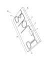
- FIG. 1 is a perspective view showing a multimode laser according to Embodiment 1.
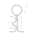
- FIG. 3 is a plan view showing a loop mirror in Embodiment 1.
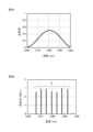
- FIG. 3A and 3B are diagrams showing the characteristics of a conventional multimode laser.
- 4A and 4B are diagrams showing the characteristics of the multimode laser according to the first embodiment.
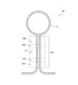
- FIG. 7 is a plan view showing a modification example (1) of the loop mirror in the first embodiment.
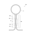
- FIG. 7 is a plan view showing a modification example (2) of the loop mirror in the first embodiment.
- FIG. 3 is a perspective view showing a multimode laser according to a second embodiment. 7 is a graph showing the reflection characteristics of a loop mirror in Embodiment 2.
- FIG. 7 is a plan view showing a modification example (1) of the loop mirror in the second embodiment.
- FIG. 7 is a plan view showing a modification example (2) of the loop mirror in Embodiment 2;
- FIG. 7 is a plan view showing a modification (3) of the loop mirror in Embodiment 2;
- FIG. 1 is a perspective view showing a multimode laser 1 according to the first embodiment.
- the multimode laser 1 is a laser that emits laser light with wavelengths ⁇ 1 to ⁇ N in a desired oscillation wavelength range.
- N is an integer of 2 or more.
- a multimode laser 1 includes a semiconductor amplifier 2 and a semiconductor substrate 3.
- Semiconductor amplifier 2 amplifies laser light.
- a waveguide 4 is formed on the semiconductor substrate 3, and the waveguide 4 constitutes a ring resonant filter 5 and a loop mirror 6.
- a laser resonator 7 of the multimode laser 1 is configured between a semiconductor amplifier 2 and a loop mirror 6 provided on a semiconductor substrate 3.
- An HR (High Reflection) coat is applied to the rear surface 2A of the semiconductor amplifier 2 (the surface opposite to the laser light emission surface 2B).
- HR coating high reflectance can be obtained in a wide wavelength band including the desired oscillation wavelength range.
- an AR (Anti-Reflection) coating is applied to the laser beam output surface 2B of the semiconductor amplifier 2.
- the AR coating can reduce the reflection of laser light on the emission surface 2B to almost zero.
- spontaneous emission light generated in the semiconductor amplifier 2 is amplified as a seed.
- the output surface 2B of the semiconductor amplifier 2 is optically coupled to the end of the waveguide 4 formed on the semiconductor substrate 3.
- a semiconductor amplifier having an active layer of quantum dots (hereinafter referred to as a quantum dot semiconductor amplifier) is used.
- the quantum dot semiconductor amplifier is suitable for the multimode laser 1 because it is an amplifier with less noise superimposed on the laser light of each oscillation wavelength.
- other types of semiconductor amplifiers can also be used in the multimode laser 1.
- a quantum well semiconductor amplifier may be used as the semiconductor amplifier 2.
- the semiconductor substrate 3 is a substrate on which a waveguide for propagating light is formed.
- the semiconductor substrate 3 is provided with a ring resonant filter 5 and a loop mirror 6 that are configured by the waveguide.
- the semiconductor substrate 3 is, for example, a silicon substrate, and the waveguide 4, ring resonant filter 5, and loop mirror 6 are constructed of silicon waveguides using silicon photonics technology.
- a silicon nitride (SiN) substrate may be used as the semiconductor substrate 3.
- the waveguide may be an organic waveguide.
- the ring resonant filter 5 passes light at predetermined wavelength intervals (laser light with wavelengths ⁇ 1 to ⁇ N ) from a desired oscillation wavelength range. For example, the ring resonant filter 5 emits laser light at wavelength intervals for optical communication. Note that if the ring resonant filter 5 is not provided, light having tens of thousands of wavelengths will be generated between the wavelengths of the output light, and the output power will be dispersed.
- the rear surface 2A functions as an HR mirror that completely reflects spontaneous emission light generated by passing a current through the semiconductor amplifier 2 as a seed, and the characteristic shape of the reflectance is convex in the desired oscillation wavelength range.
- Fabry-Perot resonance occurs between the loop mirror 6 and the shape of the loop mirror 6.
- the ring resonant filter 5 in the laser resonator 7 determines the wavelength of light that can pass, and only the light of the wavelength that passes is lased.
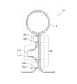
- FIG. 2 is a plan view showing the loop mirror 6 in the first embodiment.
- the loop mirror 6 is a Sagnac loop mirror equipped with a Mach-Zehnder interferometer (hereinafter referred to as MZ interferometer) 8 and a loop waveguide 9, as shown in FIG.
- MZ interferometer Mach-Zehnder interferometer
- the MZ interferometer 8 includes a directional coupler 10A, a directional coupler 10B, and a waveguide pair including a bent waveguide 11.
- the loop waveguide 9 is a waveguide formed in a loop shape, and is optically coupled to the directional coupler 10B.
- the directional coupler 10A is a first directional coupler configured by adjacent waveguides having the same width.
- the directional coupler 10B is a second directional coupler having the same waveguide width as the directional coupler 10A, and is composed of adjacent waveguides having the same width.
- the lengths of the waveguides are different between the directional coupler 10A and the directional coupler 10B. For example, as shown in FIG.
- the directional coupler 10B is formed to be longer than the directional coupler 10A.
- the waveguide lengths of the directional coupler 10A and the directional coupler 10B may be the same.
- one of the waveguides is a bent waveguide 11.
- the waveguide on the left side of the paper is a bent waveguide 11, but the waveguide on the right side of the paper may be a bent waveguide.
- FIG. 2 shows the bent waveguide 11 having one bent portion, it may be a bent waveguide having a plurality of bent portions, or both waveguides of the waveguide pair may be bent. It may also be a wave path. For example, if the waveguide on the left side of the paper is a bent waveguide bent to the right, and the waveguide on the right side of the paper is a bent waveguide bent to the right, if the lengths of the left and right bent waveguides are different from each other, then good.
- the characteristic shape of the reflectance of the loop mirror 6 can be made convex in a desired oscillation wavelength range.
- FIG. 3A is a graph showing the reflection characteristics of a loop mirror in a conventional multimode laser, and shows the reflection characteristics of a conventional general loop mirror.
- FIG. 3B is a graph showing the laser oscillation characteristics of a conventional multimode laser, and is the result of a simulation of the laser oscillation characteristics of a laser resonator configured between a loop mirror having the reflection characteristics shown in FIG. 3A and a semiconductor amplifier. It shows. Note that the laser resonance is Fabry-Perot resonance generated by spontaneous emission light generated by passing a current of 100 mA through a semiconductor amplifier.
- a conventional general loop mirror has a reflection characteristic in which the reflectance is approximately constant with respect to wavelength.
- the wavelength interval of light that resonates between a semiconductor amplifier as a gain medium and a loop mirror is determined by a resonator filter.
- the laser resonator when the loop mirror returns light to the semiconductor amplifier, the light is amplified and oscillates as a laser. If the reflectivity of the light returning to the semiconductor amplifier is small, the optical output power that can be extracted from the end of the loop mirror increases. However, if the reflectance of the loop mirror is made too small, sufficient photon density cannot be obtained and laser oscillation will not occur.
- a conventional loop mirror has a substantially constant reflectance for all wavelengths determined by the resonator filter, and in a laser resonator, it has a nearly constant reflectance for all wavelengths determined by the resonator filter. Approximately constant gain is given to the wavelength of light.
- conventional multimode lasers resonate with light in a wide wavelength range including the wavelength determined by the resonator filter, and the laser oscillation characteristics are oscillations corresponding to the gain shape of the semiconductor amplifier, as shown in Figure 3B. Becomes a characteristic. For this reason, light having a wavelength outside the oscillation wavelength range A also oscillates, resulting in a decrease in power efficiency.
- the multimode laser 1 includes a loop mirror 6 whose reflectance characteristic shape is convex in the desired oscillation wavelength range A, so that light with a wavelength outside the oscillation wavelength range A is oscillated. prevent this from happening.
- the semiconductor amplifier 2 carriers are used for optical amplification on the oscillating wavelength side, so uniform laser oscillation with small difference in optical output between wavelengths can be realized in the oscillation wavelength range A. .
- FIG. 4A is a graph showing the reflection characteristics of the loop mirror 6 in the multimode laser 1 according to the first embodiment.
- FIG. 4B is a graph showing the laser oscillation characteristics of the multimode laser 1, and simulates the laser oscillation characteristics of the laser resonator 7 configured between the loop mirror 6 and the semiconductor amplifier 2 having the reflection characteristics shown in FIG. 4A. The results are shown below. Note that the laser resonance is Fabry-Perot resonance generated by spontaneous emission light generated by passing a current of 100 mA through the semiconductor amplifier 2.
- the reflectance for light with a wavelength of less than 1265 nm and light with a wavelength of more than 1295 nm is small, and the transmission rate, which is the rate at which light is transmitted from the loop mirror 6, is correspondingly small. rate becomes higher.
- the transmission rate which is the rate at which light is transmitted from the loop mirror 6, is correspondingly small. rate becomes higher.
- laser oscillation no longer occurs in the laser resonator 7, and the optical output from the laser resonator 7 also increases.
- the desired oscillation wavelength range A from 1265 nm to 1295 nm the reflectance of the loop mirror 6 is higher than the reflectance of the same range shown in FIG. Since the transmittance becomes low, it becomes difficult to output from the laser resonator 7, and laser resonance occurs.
- the gain of the semiconductor amplifier 2 is large for light of a wavelength for which the loop mirror 6 has a large reflectance, and the gain of the semiconductor amplifier 2 is small for light of a wavelength for which the loop mirror 6 has a small reflectance.
- the gain of light is greater than the loss of light in the laser resonator 7, the light resonates and is not output from the laser resonator 7, and the light whose gain is smaller than the loss does not resonate and is output from the laser resonator 7. be done. That is, in the laser resonator 7, oscillation does not occur when the subtraction between the gain of the semiconductor amplifier 2 and the total loss becomes negative, and oscillation occurs when the subtraction becomes positive.
- the bottom portion where the reflectance is low has a small gain, so the optical output increases without oscillation.
- Light with a wavelength corresponding to the vicinity of the apex where the reflectance is high has a large gain, and therefore oscillates strongly in the laser resonator 7.
- the loop mirror 6 shown in FIG. 2 has a convex reflectance characteristic shape by changing the phase of light propagating through the waveguide. For example, the lengths of the waveguides on the left and right sides of the paper are changed using the bent waveguide 11, that is, the phase corresponding to the amount of light travels is changed. Furthermore, the directional coupler 10A is made to have wavelength characteristics with a certain period, and the directional coupler 10B is made to have wavelength characteristics with a period different from that of the directional coupler 10A. By adjusting these, it is possible to make the characteristic shape of the reflectance of the loop mirror 6 convex.
- the degree of freedom in adjusting the reflection characteristics is increased.
- a loop mirror like a bandpass filter for the wavelength of light, which reflects 100% of light of a certain wavelength and does not reflect any light of another wavelength.
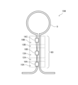
- FIG. 5 is a plan view showing a loop mirror 6A that is a modification example (1) of the loop mirror 6 in the first embodiment.
- the loop mirror 6A includes a directional coupler 10A, a directional coupler 10B, a propagation constant conversion waveguide 12A, a non-coupling waveguide 13, and a propagation constant conversion waveguide 12B.
- the loop waveguide 9 is a waveguide formed in a loop shape, and is optically coupled to the directional coupler 10B.
- the directional coupler 10A is a first directional coupler constituted by adjacent waveguides having the same width.
- the directional coupler 10B is a second directional coupler having the same waveguide width as the directional coupler 10A, and is composed of adjacent waveguides having the same width. Furthermore, the lengths of the waveguides are different between the directional coupler 10A and the directional coupler 10B. For example, as shown in FIG. 5, the directional coupler 10B is formed to be longer than the directional coupler 10A. However, the waveguide lengths of the directional coupler 10A and the directional coupler 10B may be the same.
- the non-coupled waveguide 13 is a waveguide in which at least one waveguide has a waveguide width different from that of the directional coupler 10A and the directional coupler 10B.
- the non-coupled waveguide 13 has a narrower waveguide width than the directional couplers 10A and 10B.
- one of the adjacent waveguides has a narrow waveguide width, and the distance between the waveguides is such that there is no optical coupling, that is, no mode coupling.
- the propagation constant conversion waveguide 12A is provided between the directional coupler 10A and the non-coupled waveguide 13, and is optically connected to the non-coupled waveguide 13 from the end optically coupled to the directional coupler 10A.
- This is a first propagation constant conversion waveguide whose waveguide width gradually changes until it reaches the coupled end.
- the propagation constant conversion waveguide 12A is guided from the end optically coupled to the directional coupler 10A to the end optically coupled to the non-coupled waveguide 13. It is a tapered waveguide with a waveguide width that gradually decreases.
- the propagation constant conversion waveguide 12B is provided between the non-coupling waveguide 13 and the directional coupler 10B, and is optically connected to the directional coupler 10B from the end optically coupled to the non-coupling waveguide 13.
- This is a second propagation constant conversion waveguide whose waveguide width gradually changes up to the coupled end.
- the propagation constant conversion waveguide 12B is guided from the end optically coupled to the non-coupled waveguide 13 to the end optically coupled to the directional coupler 10B. It is a tapered waveguide with a waveguide width that gradually increases.
- the propagation constant conversion waveguide 12A and the propagation constant conversion waveguide 12B are waveguides that adiabatically change the propagation constant of light. By changing the propagation constant of light, a phase difference between adjacent waveguides can be generated without using the bent waveguide 11. Using this, it is possible to make the characteristic shape of the reflectance of the loop mirror 6A convex. Note that the propagation constant conversion waveguide 12A, the uncoupled waveguide 13, and the propagation constant conversion waveguide 12B only need to be able to generate a phase difference with an adjacent waveguide. Therefore, although energy loss occurs, a multimode interference (MMI) type waveguide that is non-adiabatic and changes the propagation constant may be used for the loop mirror 6A.
- MMI multimode interference
- the non-coupled waveguide 13 in FIG. 5 has a configuration in which the width of the waveguide on the left side of the paper is narrowed, the width of the waveguide on the right side of the paper may be narrowed.
- the width of either the waveguide on the left side or the right side of the page may be wider than that of the directional couplers 10A and 10B. Even if the width of the waveguide is adjusted in this way, the propagation constant of light can be changed even if the waveguide is a non-coupled waveguide 13.
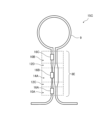
- FIG. 6 is a plan view showing a loop mirror 6B that is a modification example (2) of the loop mirror 6 in the first embodiment.
- the loop mirror 6B includes a directional coupler 10A, a directional coupler 10B, a propagation constant conversion waveguide 12C, a non-coupling waveguide 14, and a propagation constant conversion waveguide 12D.
- the loop waveguide 9 is a waveguide formed in a loop shape, and is optically coupled to the directional coupler 10B.
- the directional coupler 10A is a first directional coupler constituted by adjacent waveguides having the same width.
- the directional coupler 10B is a second directional coupler having the same waveguide width as the directional coupler 10A, and is composed of adjacent waveguides having the same width. Furthermore, the lengths of the waveguides are different between the directional coupler 10A and the directional coupler 10B. For example, as shown in FIG. 6, the directional coupler 10B is formed to be longer than the directional coupler 10A. However, the waveguide lengths of the directional coupler 10A and the directional coupler 10B may be the same.
- the non-coupled waveguide 14 is a waveguide in which at least one waveguide has a waveguide width different from that of the directional coupler 10A and the directional coupler 10B.
- the non-coupled waveguide 14 has a wider waveguide width than the directional couplers 10A and 10B.
- one of the adjacent waveguides has a wide waveguide width, and the other has a narrow waveguide width.
- the distance between the waveguides in the non-coupled waveguide 14 is such that no optical coupling occurs, that is, no mode coupling occurs.
- the propagation constant conversion waveguide 12C is provided between the directional coupler 10A and the non-coupled waveguide 14, and is optically connected to the non-coupled waveguide 14 from the end optically coupled to the directional coupler 10A.
- This is a first propagation constant conversion waveguide whose waveguide width gradually changes until it reaches the coupled end.
- one waveguide constituting the propagation constant conversion waveguide 12C is optically coupled to the uncoupled waveguide 14 from the end optically coupled to the directional coupler 10A. It is a tapered waveguide whose width gradually increases until it reaches the end.
- the other waveguide constituting the propagation constant conversion waveguide 12C is guided from the end optically coupled to the directional coupler 10A to the end optically coupled to the non-coupled waveguide 13. It is a tapered waveguide with a waveguide width that gradually decreases.
- the propagation constant conversion waveguide 12D is provided between the non-coupled waveguide 14 and the directional coupler 10B, and is optically connected to the directional coupler 10B from the end optically coupled to the non-coupled waveguide 14.
- This is a second propagation constant conversion waveguide whose waveguide width gradually changes up to the coupled end.
- one waveguide constituting the propagation constant conversion waveguide 12D is optically coupled to the uncoupled waveguide 14 from the end optically coupled to the directional coupler 10A. It is a tapered waveguide whose width gradually decreases until it reaches the end.
- the other waveguide constituting the propagation constant conversion waveguide 12D is guided from the end optically coupled to the non-coupled waveguide 14 to the end optically coupled to the directional coupler 10B. It is a tapered waveguide with a waveguide width that gradually increases.
- the propagation constant conversion waveguide 12C and the propagation constant conversion waveguide 12D are waveguides that adiabatically change the propagation constant of light. By changing the propagation constant of light, a phase difference between adjacent waveguides can be generated without using the bent waveguide 11. Using this, it is possible to make the characteristic shape of the reflectance of the loop mirror 6B convex. Note that the propagation constant conversion waveguide 12C, the uncoupled waveguide 14, and the propagation constant conversion waveguide 12D only need to be able to generate a phase difference with an adjacent waveguide. Therefore, although energy loss occurs, a multimode interference (MMI) type waveguide that is non-adiabatic and changes the propagation constant may be used for the loop mirror 6B.
- MMI multimode interference
- the multimode laser 1 is configured between the semiconductor amplifier 2, the loop mirror 6 configured by the waveguide formed on the semiconductor substrate 3, and the semiconductor amplifier 2.
- a laser resonator 7 is provided.
- the characteristic shape of the reflectance of the loop mirror 6 is convex in the oscillation wavelength range. Since oscillation of laser light having a wavelength outside the oscillation wavelength range is suppressed, the multimode laser 1 can suppress laser oscillation outside the oscillation wavelength range and improve power efficiency.
- the semiconductor amplifier 2 has an active layer of quantum dots.
- noise superimposed on laser light for each oscillation wavelength is reduced.
- the loop mirror 6 includes a directional coupler 10A, which is a waveguide adjacent to each other, and a directional coupler 10B, which has the same waveguide width as the directional coupler 10A. and a pair of waveguides provided between the directional coupler 10A and the directional coupler 10B, one of which is a bent waveguide 11, and a loop guide optically coupled to the directional coupler 10B. It has a wave path 9.
- the waveguide in this manner, it is possible to realize the loop mirror 6 having a characteristic shape of reflectance that is convex in a desired oscillation wavelength range.
- the loop mirror 6A or 6B is connected to the directional coupler 10A, the directional coupler 10B, the non-coupled waveguide 13 or 14, and the directional coupler 10A.
- the waveguide width is provided between the waveguide 13 or 14 and extends from the end optically coupled to the directional coupler 10A to the end optically coupled to the non-coupled waveguide 13 or 14.
- An end portion provided between the gradually changing propagation constant conversion waveguide 12A or 12C, the non-coupled waveguide 13 or 14, and the directional coupler 10B, and optically coupled to the non-coupled waveguide 13 or 14.
- a propagation constant conversion waveguide 12B or 12D whose waveguide width gradually changes from the end to the end optically coupled to the directional coupler 10B, and a loop guide optically coupled to the directional coupler 10B. It has a wave path 9.
- the waveguide width By adjusting the waveguide width in this way, it is possible to realize the loop mirror 6A or 6B having a characteristic shape of reflectance that is convex in a desired oscillation wavelength range.
- the non-coupled waveguide 13 has a waveguide width narrower than that of the directional coupler 10A and the directional coupler 10B.
- the waveguide width of the propagation constant conversion waveguide 12A gradually decreases from the end optically coupled to the directional coupler 10A to the end optically coupled to the non-coupled waveguide 13.
- the waveguide width of the propagation constant conversion waveguide 12B gradually increases from the end optically coupled to the non-coupled waveguide 13 to the end optically coupled to the directional coupler 10B.
- the same effect can be obtained even when the non-coupled waveguide 13 has a wider waveguide width than the directional coupler 10A and the directional coupler 10B.
- the bent waveguide 11 light is likely to be emitted when the waveguide is bent, and in order to suppress loss, it is necessary to increase the bending radius of the waveguide, which is a design constraint.
- the propagation constant using the non-coupled waveguide 13 it is possible to generate a phase difference between adjacent waveguides without using a bent waveguide, increasing the degree of freedom in design.
- the uncoupled waveguide 14 has one of the adjacent waveguides having a wider waveguide width than the directional coupler 10A and the directional coupler 10B, and the adjacent waveguide
- the other waveguide has a narrower waveguide width than directional couplers 10A and 10B.
- One of the waveguides constituting the propagation constant conversion waveguide 12C has a waveguide width from the end optically coupled to the directional coupler 10A to the end optically coupled to the non-coupled waveguide 14. gradually increases.
- the other waveguide constituting the propagation constant conversion waveguide 12C is guided from the end optically coupled to the directional coupler 10A to the end optically coupled to the non-coupled waveguide 14. The wave width gradually decreases.
- One of the waveguides constituting the propagation constant conversion waveguide 12D has a waveguide width from the end optically coupled to the non-coupled waveguide 14 to the end optically coupled to the directional coupler 10B. gradually decreases. Further, the other waveguide constituting the propagation constant conversion waveguide 12D is guided from the end optically coupled to the non-coupled waveguide 14 to the end optically coupled to the directional coupler 10B. The wave path width gradually increases. By adjusting the waveguide width in this manner, it is possible to realize the loop mirror 6B having a convex reflectance characteristic shape in a desired oscillation wavelength range. Note that the loop mirror 6B shown in FIG.
- the loop mirror 6 has a larger difference in waveguide width between the waveguides shown on the left and right sides of the paper than the loop mirror 6A shown in FIG.
- the loop mirror 6B has a larger difference in propagation constant between adjacent waveguides than the loop mirror 6A, so a desired phase difference can be provided with a short waveguide length, making the loop mirror more compact. Is possible.
- FIG. 7 is a perspective view showing a multimode laser 1A according to the second embodiment.
- the multimode laser 1A is a laser that emits laser light with wavelengths ⁇ 1 to ⁇ N in a desired oscillation wavelength range. N is an integer of 2 or more.
- the multimode laser 1A includes a semiconductor amplifier 2 and a semiconductor substrate 3A.
- a waveguide 4 is formed on the semiconductor substrate 3A, and the waveguide 4 constitutes a ring resonant filter 5, a loop mirror 6, and a loop mirror 15.
- the laser resonator 7A of the multimode laser 1A is configured with a semiconductor amplifier 2 disposed between a loop mirror 6 and a loop mirror 15. Note that in the semiconductor substrate 3A, the positions of the semiconductor amplifier 2 and the ring resonant filter 5 may be exchanged.
- the front and rear surfaces of the semiconductor amplifier 2 are not coated with an HR coat and an AR coat, and are optically coupled to the waveguide 4, and are surfaces through which light enters and exits.
- spontaneous emission light generated in the semiconductor amplifier 2 is amplified as a seed.
- a quantum dot semiconductor amplifier is used as the semiconductor amplifier 2.
- the quantum dot semiconductor amplifier is suitable for the multimode laser 1A because it is an amplifier with less noise superimposed on the laser light of each oscillation wavelength. Note that other types of semiconductor amplifiers can also be used in the multimode laser 1A. For example, a quantum well semiconductor amplifier may be used as the semiconductor amplifier 2.
- the semiconductor substrate 3A is a substrate on which a waveguide for propagating light is formed.
- a ring resonant filter 5, a loop mirror 6, and a loop mirror 15 each formed of a waveguide are integrally formed on the semiconductor substrate 3A.
- the semiconductor substrate 3A is, for example, a silicon substrate, and the waveguide 4, ring resonant filter 5, loop mirror 6, and loop mirror 15 are constructed of silicon waveguides using silicon photonics technology.
- a silicon nitride (SiN) substrate may be used as the semiconductor substrate 3A.
- the waveguide may be an organic waveguide.
- the loop mirror 6 is a first loop mirror whose characteristic shape of reflectance is convex in the desired oscillation wavelength range A. Like the ring resonant filter 5, the loop mirror 6 is configured by a waveguide formed on the semiconductor substrate 3A.
- the loop mirror 6 is a Sagnac loop mirror equipped with an MZ interferometer 8 and a loop waveguide 9, as shown in FIG.
- the loop mirror 15 is a second loop mirror that performs almost total reflection (reflectance close to 100%) in a wide wavelength band including the desired oscillation wavelength range A.
- the loop mirror 15 is configured by a waveguide in the semiconductor substrate 3A, and forms a laser resonator 7A with the loop mirror 6.
- Fabry-Perot resonance occurs between the loop mirror 15 and the loop mirror 6 using spontaneous emission light generated by passing a current through the semiconductor amplifier 2 as a seed.
- the ring resonant filter 5 in the laser resonator 7A determines the wavelength of light that can pass, and only the light of the wavelength that passes oscillates as a laser.
- the multimode laser 1 in order to optically couple the semiconductor amplifier 2 and the semiconductor substrate 3, the relative positions of the semiconductor amplifier 2 and the semiconductor substrate 3 need to be mounted with high accuracy. That is, the multimode laser 1 has a severe positional deviation tolerance required for laser oscillation.
- the compound semiconductor portion such as the semiconductor amplifier 2 can be manufactured by process processing.
- the multimode laser 1A can suppress optical loss and realize more efficient laser oscillation.
- FIG. 8 is a graph showing the reflection characteristics of the loop mirror 15 in the second embodiment.
- the loop mirror 15 may have the same structure as the loop mirror 6 shown in FIG. In this case, the loop mirror 15 may have the same structure as the loop mirror 6A shown in FIG. 5, or may have the same structure as the loop mirror 6B shown in FIG.
- the characteristic shape of the reflectance of the loop mirror 6 and the loop mirror 15 is made convex in the desired oscillation wavelength range A.
- the reflection characteristics of the loop mirror 6 and the loop mirror 15 it is possible to suppress the oscillation of light having a wavelength that is difficult to oscillate or that is not desired to oscillate in the laser resonator 7A. Note that the light output from the end of the loop mirror 15 to the outside of the semiconductor substrate 3A is not used.
- FIG. 9 is a plan view showing a loop mirror 15A that is a modification example (1) of the loop mirror 15 in the second embodiment.
- the loop mirror 15A includes a loop waveguide 9, a directional coupler 10C, a directional coupler 10D, and a bent waveguide 11A.
- the directional coupler 10C is provided with a phase adjustment section 16A
- the bent waveguide 11A is provided with a phase adjustment section 16B
- the directional coupler 10D is provided with a phase adjustment section 16C.
- the loop waveguide 9 is a waveguide formed in a loop shape, and is optically coupled to the directional coupler 10D.
- the directional coupler 10C is a first directional coupler configured by adjacent waveguides having the same width.
- the directional coupler 10D is a second directional coupler having the same waveguide width as the directional coupler 10C, and is composed of adjacent waveguides having the same width.
- the lengths of the waveguides are different between the directional coupler 10C and the directional coupler 10D.
- the directional coupler 10D is formed to be longer than the directional coupler 10C.
- One of the waveguide pairs provided between the directional coupler 10C and the directional coupler 10D is a bent waveguide 11A.
- the phase adjustment unit 16A adjusts the phase of light propagating through the directional coupler 10C.
- the phase adjustment section 16B adjusts the phase of light propagating through the bent waveguide 11A.
- the phase adjustment section 16C adjusts the phase of light propagating through the directional coupler 10D.
- phase adjustment units 16A, 16B, and 16C are, for example, resistive elements that change the phase of light using heat when current is passed through them. Furthermore, the phase adjustment sections 16A, 16B, and 16C may be diodes whose refractive index changes by changing the density of carriers and accordingly change the phase of light. Note that the phase adjustment section may be provided in any one of the directional coupler 10C, the directional coupler 10D, and the bent waveguide 11A. Furthermore, phase adjustment sections 16A, 16B, and 16C may be provided for the loop mirror 6.
- FIG. 10 is a plan view showing a loop mirror 15B which is a modified example (2) of the loop mirror 15 in the second embodiment.
- the loop mirror 15B includes a directional coupler 10A, a directional coupler 10B, a propagation constant conversion waveguide 12A, a non-coupling waveguide 13A, and a propagation constant conversion waveguide 12B.
- One waveguide constituting the directional coupler 10A is provided with a phase adjustment section 16A
- one waveguide constituting the non-coupled waveguide 13A is provided with a phase adjustment section 16B.
- a phase adjustment section 16C is provided in one of the waveguides constituting 10D. Note that, unlike in FIG.
- a phase adjustment section 16A is provided in the other waveguide constituting the directional coupler 10A, and a phase adjustment section 16B is provided in the other waveguide constituting the non-coupled waveguide 13A.
- a phase adjustment section 16C may be provided in the other waveguide constituting the coupler 10D.
- the loop waveguide 9 is a waveguide formed in a loop shape, and is optically coupled to the directional coupler 10B.
- the directional coupler 10A is a first directional coupler constituted by adjacent waveguides having the same width.
- the directional coupler 10B is a second directional coupler having the same waveguide width as the directional coupler 10A, and is composed of adjacent waveguides having the same width.
- the lengths of the waveguides are different between the directional coupler 10A and the directional coupler 10B.
- the directional coupler 10B is formed to be longer than the directional coupler 10A.
- the waveguide lengths of the directional coupler 10A and the directional coupler 10B may be the same.
- the phase adjustment unit 16A adjusts the phase of light propagating through the directional coupler 10A.
- the phase adjustment section 16B adjusts the phase of light propagating through the non-coupled waveguide 13A.
- the phase adjustment section 16C adjusts the phase of light propagating through the directional coupler 10B.
- the non-coupled waveguide 13A is a waveguide in which at least one waveguide has a waveguide width different from that of the directional coupler 10A and the directional coupler 10B.
- the non-coupled waveguide 13A has a narrower waveguide width than the directional couplers 10A and 10B.
- one of the adjacent waveguides has a narrow waveguide width, and the distance between the waveguides is such that there is no optical coupling, that is, no mode coupling.
- the propagation constant conversion waveguide 12A is provided between the directional coupler 10A and the non-coupled waveguide 13A, and is optically connected to the non-coupled waveguide 13A from the end optically coupled to the directional coupler 10A.
- This is a first propagation constant conversion waveguide whose waveguide width gradually changes until it reaches the coupled end.
- the propagation constant conversion waveguide 12A is guided from the end optically coupled to the directional coupler 10A to the end optically coupled to the uncoupled waveguide 13A. It is a tapered waveguide with a waveguide width that gradually decreases.
- the propagation constant conversion waveguide 12B is provided between the non-coupling waveguide 13A and the directional coupler 10B, and is optically connected to the directional coupler 10B from the end optically coupled to the non-coupling waveguide 13A.
- This is a second propagation constant conversion waveguide whose waveguide width gradually changes up to the coupled end.
- the propagation constant conversion waveguide 12B is guided from the end optically coupled to the non-coupled waveguide 13A to the end optically coupled to the directional coupler 10B. It is a tapered waveguide with a waveguide width that gradually increases.
- the non-coupled waveguide 13A in FIG. 10 has a configuration in which the width of the waveguide on the left side of the paper is narrowed, the width of the waveguide on the right side of the paper may be narrowed.
- the width of either the waveguide on the left side or the right side of the page may be wider than that of the directional couplers 10A and 10B. Even if the width of the waveguide is adjusted in this way, the propagation constant of light can be changed even if the waveguide is a non-coupled waveguide 13.
- FIG. 11 is a plan view showing a loop mirror 15C which is a modified example (3) of the loop mirror 15 in the second embodiment.
- the loop mirror 15C includes a directional coupler 10A, a directional coupler 10B, a propagation constant conversion waveguide 12C, a non-coupling waveguide 14A, and a propagation constant conversion waveguide 12D.
- One waveguide constituting the directional coupler 10A is provided with a phase adjustment section 16A
- one waveguide constituting the non-coupled waveguide 14A is provided with a phase adjustment section 16B.
- a phase adjustment section 16C is provided in one of the waveguides constituting 10D. Note that, unlike in FIG.
- a phase adjustment section 16A is provided in the other waveguide constituting the directional coupler 10A
- a phase adjustment section 16B is provided in the other waveguide constituting the non-coupled waveguide 14A
- the directional coupler 10A is provided with a phase adjustment section 16B.
- a phase adjustment section 16C may be provided in the other waveguide constituting the coupler 10D.
- the loop waveguide 9 is a waveguide formed in a loop shape, and is optically coupled to the directional coupler 10B.
- the directional coupler 10A is a first directional coupler constituted by adjacent waveguides having the same width.
- the directional coupler 10B is a second directional coupler having the same waveguide width as the directional coupler 10A, and is composed of adjacent waveguides having the same width.
- the lengths of the waveguides are different between the directional coupler 10A and the directional coupler 10B.
- the directional coupler 10B is formed to be longer than the directional coupler 10A.
- the waveguide lengths of the directional coupler 10A and the directional coupler 10B may be the same.
- the non-coupling waveguide 14A is a waveguide in which at least one waveguide has a waveguide width different from that of the directional coupler 10A and the directional coupler 10B.
- the non-coupled waveguide 14A has a wider waveguide width than the directional couplers 10A and 10B.
- one of the adjacent waveguides has a wide waveguide width, and the other has a narrow waveguide width.
- the distance between the waveguides in the non-coupling waveguide 14A is such that no optical coupling occurs, that is, no mode coupling occurs.
- the propagation constant conversion waveguide 12C is provided between the directional coupler 10A and the non-coupled waveguide 14A, and is optically connected to the non-coupled waveguide 14A from the end optically coupled to the directional coupler 10A.
- This is a first propagation constant conversion waveguide whose waveguide width gradually changes until it reaches the coupled end.
- one waveguide constituting the propagation constant conversion waveguide 12C is optically coupled to the uncoupled waveguide 14A from the end optically coupled to the directional coupler 10A. It is a tapered waveguide whose width gradually increases until it reaches the end.
- the other waveguide constituting the propagation constant conversion waveguide 12C is guided from the end optically coupled to the directional coupler 10A to the end optically coupled to the non-coupled waveguide 13. It is a tapered waveguide with a waveguide width that gradually decreases.
- the propagation constant conversion waveguide 12D is provided between the non-coupled waveguide 14A and the directional coupler 10B, and is optically connected to the directional coupler 10B from the end optically coupled to the non-coupled waveguide 14A.
- This is a second propagation constant conversion waveguide whose waveguide width gradually changes up to the coupled end.
- one waveguide constituting the propagation constant conversion waveguide 12D is optically coupled to the uncoupled waveguide 14A from the end optically coupled to the directional coupler 10A. It is a tapered waveguide whose width gradually decreases until it reaches the end.
- the other waveguide constituting the propagation constant conversion waveguide 12D is guided from the end optically coupled to the non-coupled waveguide 14A to the end optically coupled to the directional coupler 10B. It is a tapered waveguide with a waveguide width that gradually increases.
- the phase adjustment unit 16A adjusts the phase of light propagating through the directional coupler 10A.
- the phase adjustment section 16B adjusts the phase of light propagating through the non-coupled waveguide 14A.
- the phase adjustment section 16C adjusts the phase of light propagating through the directional coupler 10B. Thereby, the characteristic shape of the reflectance of the loop mirror 15C can be made convex in the desired oscillation wavelength range A.
- the semiconductor amplifier 2 is provided between the semiconductor amplifier 2 and the loop mirror 6 and the loop mirror 15, which are configured by the waveguide formed in the semiconductor substrate 3A.
- a laser resonator 7A arranged and configured is provided.
- the characteristic shape of the reflectance of the loop mirror 6 is convex in the oscillation wavelength range. Oscillation of laser light having a wavelength outside the oscillation wavelength range is suppressed, and the multimode laser 1A can suppress laser oscillation outside the oscillation wavelength range.
- the semiconductor amplifier 2 has an active layer of quantum dots.
- noise superimposed on laser light for each oscillation wavelength is reduced.
- the laser resonator 7A includes a loop mirror 6. Thereby, it is possible to provide a laser resonator 7A having a loop mirror 6 whose characteristic shape of reflectance is convex in a desired oscillation wavelength range.
- the laser resonator 7A includes a loop mirror 6A or 6B. Thereby, it is possible to provide a laser resonator 7A having a loop mirror 6 or 6B whose characteristic shape of reflectance is convex in a desired oscillation wavelength range.
- the characteristic shape of the reflectance of the loop mirror 15 is convex in the oscillation wavelength range. Therefore, it is possible to provide a laser resonator 7A having a loop mirror 15 whose characteristic shape of reflectance is convex in a desired oscillation wavelength range.
- the loop mirror 15 includes a directional coupler 10A, which is a waveguide adjacent to each other, and a directional coupler 10B, which has the same waveguide width as the directional coupler 10A. and a pair of waveguides provided between the directional coupler 10A and the directional coupler 10B, one of which is a bent waveguide 11, and a loop guide optically coupled to the directional coupler 10B. It has a wave path 9.
- the waveguide in this way, it is possible to realize the loop mirror 15 having a characteristic shape of reflectance that is convex in a desired oscillation wavelength range.
- the loop mirror 15 includes a directional coupler 10A, which is a waveguide adjacent to each other, and a directional coupler 10B, which has the same waveguide width as the directional coupler 10A. , a non-coupling waveguide 13 or 14 in which at least one waveguide has a waveguide width different from that of the directional coupler 10A and the directional coupler 10B, and the directional coupler 10A and the non-coupling waveguide 13 or 14. , and the waveguide width gradually changes from the end optically coupled to the directional coupler 10A to the end optically coupled to the non-coupled waveguide 13 or 14.
- the directional coupler is provided between the constant conversion waveguide 12A or 12C, the non-coupled waveguide 13 or 14, and the directional coupler 10B, and is connected to the end optically coupled to the non-coupled waveguide 13 or 14.
- a propagation constant conversion waveguide 12B or 12D whose waveguide width gradually changes up to the end optically coupled to the directional coupler 10B, and a loop waveguide 9 optically coupled to the directional coupler 10B. have By adjusting the waveguide width in this way, it is possible to realize the loop mirror 15 having a convex reflectance characteristic shape in a desired oscillation wavelength range.
- one of the non-coupled waveguides 13 has a narrower waveguide width than the directional couplers 10A and 10B.
- the waveguide width of the propagation constant conversion waveguide 12A gradually decreases from the end optically coupled to the directional coupler 10A to the end optically coupled to the non-coupled waveguide 13.
- the waveguide width of the propagation constant conversion waveguide 12B gradually increases from the end optically coupled to the non-coupled waveguide 13 to the end optically coupled to the directional coupler 10B.
- the same effect can be obtained even when the non-coupled waveguide 13 has a wider waveguide width than the directional coupler 10A and the directional coupler 10B.
- the bent waveguide 11 light is likely to be emitted when the waveguide is bent, and in order to suppress loss, it is necessary to increase the bending radius of the waveguide, which is a design constraint.
- the propagation constant using the non-coupled waveguide 13 it is possible to generate a phase difference between adjacent waveguides without using a bent waveguide, increasing the degree of freedom in design.
- one of the adjacent waveguides 14 has a wider waveguide width than the directional coupler 10A and the directional coupler 10B, and The other waveguide has a narrower waveguide width than directional couplers 10A and 10B.
- One of the waveguides constituting the propagation constant conversion waveguide 12C has a waveguide width from the end optically coupled to the directional coupler 10A to the end optically coupled to the non-coupled waveguide 14. gradually increases. Further, the other waveguide constituting the propagation constant conversion waveguide 12C is guided from the end optically coupled to the directional coupler 10A to the end optically coupled to the non-coupled waveguide 14. The wave width gradually decreases.
- One of the waveguides constituting the propagation constant conversion waveguide 12D has a waveguide width from the end optically coupled to the non-coupled waveguide 14 to the end optically coupled to the directional coupler 10B. gradually decreases. Further, the other waveguide constituting the propagation constant conversion waveguide 12D is guided from the end optically coupled to the non-coupled waveguide 14 to the end optically coupled to the directional coupler 10B. The wave path width gradually increases. By adjusting the waveguide width in this way, it is possible to realize the loop mirror 15 having a convex reflectance characteristic shape in a desired oscillation wavelength range. Note that the loop mirror 15, which has the same configuration as the loop mirror 6B shown in FIG. The difference is getting bigger.
- the loop mirror 15 having the same configuration as the loop mirror 6B has a larger difference in propagation constant between adjacent waveguides than the loop mirror 15 having the same configuration as the loop mirror 6A. It is possible to provide a phase difference and make the loop mirror more compact.
- the loop mirror 15A is optically coupled to the bent waveguide 11A, the directional coupler 10C optically coupled to the bent waveguide 11A, and the bent waveguide 11A.
- Each of the directional couplers 10D includes phase adjustment sections 16A, 16B, and 16C that adjust the phase of light propagating through the waveguide.
- the phase adjustment section 16A adjusts the phase of the light propagating through the directional coupler 10C
- the phase adjustment section 16B adjusts the phase of the light propagating through the bent waveguide 11A
- the phase adjustment section 16C adjusts the phase of the light propagating through the directional coupler 10D. Adjust the phase of propagating light.
- the characteristic shape of the reflectance of the loop mirror 15A can be made convex in the desired oscillation wavelength range A.
- the loop mirror 15B or 15C is provided in each of the non-coupling waveguide 13A or 14A, the directional coupler 10A, and the directional coupler 10B, and is configured to control the light propagating through the waveguide It includes phase adjustment sections 16A to 16C that adjust the phase of the.
- the characteristic shape of the reflectance of the loop mirror 15B or 15C can be made convex in the desired oscillation wavelength range A.
- a semiconductor amplifier comprising a loop mirror configured by a waveguide formed on a substrate and a laser resonator configured between the semiconductor amplifier, A multimode laser characterized in that the characteristic shape of the reflectance of the loop mirror is convex in the oscillation wavelength range.
- a multimode laser characterized in that the characteristic shape of the reflectance of the loop mirror is convex in the oscillation wavelength range.
- the loop mirror is a first directional coupler which is a waveguide adjacent to each other; a second directional coupler having the same waveguide width as the first directional coupler; a waveguide pair provided between the first directional coupler and the second directional coupler, one waveguide being a bent waveguide;
- the multimode laser according to appendix 1 or 2 further comprising a loop waveguide optically coupled to the second directional coupler.
- the loop mirror is a first directional coupler which is a waveguide adjacent to each other; a second directional coupler having the same waveguide width as the first directional coupler; a non-coupled waveguide in which at least one waveguide has a waveguide width different from that of the first directional coupler and the second directional coupler; provided between the first directional coupler and the non-coupled waveguide, and optically coupled to the non-coupled waveguide from an end optically coupled to the first directional coupler.
- a first propagation constant conversion waveguide whose waveguide width gradually changes up to the end thereof; provided between the non-coupling waveguide and the second directional coupler, and optically coupled to the second directional coupler from an end optically coupled to the non-coupling waveguide.
- a second propagation constant conversion waveguide whose waveguide width gradually changes up to the end thereof;
- the multimode laser according to appendix 1 or 2 further comprising a loop waveguide optically coupled to the second directional coupler.
- the uncoupled waveguide has one waveguide having a narrower waveguide width than the first directional coupler and the second directional coupler
- the first propagation constant conversion waveguide has a waveguide width from an end optically coupled to the first directional coupler to an end optically coupled to the non-coupled waveguide. gradually decreases
- the second propagation constant conversion waveguide has a waveguide width from an end optically coupled to the non-coupled waveguide to an end optically coupled to the second directional coupler.
- the multimode laser according to appendix 4, wherein the multimode laser gradually increases.
- one waveguide has a wider waveguide width than the first directional coupler and the second directional coupler
- the first propagation constant conversion waveguide has a waveguide width from an end optically coupled to the first directional coupler to an end optically coupled to the non-coupled waveguide. gradually increases
- the second propagation constant conversion waveguide has a waveguide width from an end optically coupled to the non-coupled waveguide to an end optically coupled to the second directional coupler.
- the multimode laser according to appendix 4 or 5, wherein the multimode laser gradually decreases.
- Appendix 7 a semiconductor amplifier; a laser resonator configured by disposing the semiconductor amplifier between a first loop mirror and a second loop mirror configured by a waveguide formed on a substrate, A multimode laser characterized in that the characteristic shape of the reflectance of the first loop mirror is convex in the oscillation wavelength range.
- Appendix 8 The multimode laser according to appendix 7, wherein the semiconductor amplifier has an active layer of quantum dots.
- the first loop mirror is a first directional coupler which is a waveguide adjacent to each other; a second directional coupler having the same waveguide width as the first directional coupler; a waveguide pair provided between the first directional coupler and the second directional coupler, one waveguide being a bent waveguide;
- the first loop mirror is a first directional coupler which is a waveguide adjacent to each other; a second directional coupler having the same waveguide width as the first directional coupler; a non-coupled waveguide in which at least one waveguide has a waveguide width different from that of the first directional coupler and the second directional coupler; provided between the first directional coupler and the non-coupled waveguide, and optically coupled to the non-coupled waveguide from an end optically coupled to the first directional coupler.
- a first propagation constant conversion waveguide whose waveguide width gradually changes up to the end thereof; provided between the non-coupling waveguide and the second directional coupler, and optically coupled to the second directional coupler from an end optically coupled to the non-coupling waveguide.
- a second propagation constant conversion waveguide whose waveguide width gradually changes up to the end thereof;
- the uncoupled waveguide has one waveguide having a narrower waveguide width than the first directional coupler and the second directional coupler
- the first propagation constant conversion waveguide has a waveguide width from an end optically coupled to the first directional coupler to an end optically coupled to the non-coupled waveguide. gradually decreases
- the second propagation constant conversion waveguide has a waveguide width from an end optically coupled to the non-coupled waveguide to an end optically coupled to the second directional coupler.
- the multimode laser according to appendix 10, wherein the multimode laser increases gradually.
- one waveguide has a wider waveguide width than the first directional coupler and the second directional coupler
- the first propagation constant conversion waveguide has a waveguide width from an end optically coupled to the first directional coupler to an end optically coupled to the non-coupled waveguide. gradually increases
- the second propagation constant conversion waveguide has a waveguide width from an end optically coupled to the non-coupled waveguide to an end optically coupled to the second directional coupler.
- the multimode laser according to appendix 10 or 11, wherein the multimode laser gradually decreases.
- the multimode laser according to any one of appendices 7 to 12, wherein the characteristic shape of the reflectance of the second loop mirror is convex in the oscillation wavelength range.
- the second loop mirror is a first directional coupler which is a waveguide adjacent to each other; a second directional coupler having the same waveguide width as the first directional coupler; a waveguide pair provided between the first directional coupler and the second directional coupler, one waveguide being a bent waveguide;
- the second loop mirror is a first directional coupler which is a waveguide adjacent to each other; a second directional coupler having the same waveguide width as the first directional coupler; a non-coupled waveguide in which at least one waveguide has a waveguide width different from that of the first directional coupler and the second directional coupler; provided between the first directional coupler and the non-coupled waveguide, and optically coupled to the non-coupled waveguide from an end optically coupled to the first directional coupler.
- a first propagation constant conversion waveguide whose waveguide width gradually changes up to the end thereof; provided between the non-coupling waveguide and the second directional coupler, and optically coupled to the second directional coupler from an end optically coupled to the non-coupling waveguide.
- a second propagation constant conversion waveguide whose waveguide width gradually changes up to the end thereof;
- the uncoupled waveguide has one waveguide having a narrower waveguide width than the first directional coupler and the second directional coupler
- the first propagation constant conversion waveguide has a waveguide width from an end optically coupled to the first directional coupler to an end optically coupled to the non-coupled waveguide. gradually decreases
- the second propagation constant conversion waveguide has a waveguide width from an end optically coupled to the non-coupled waveguide to an end optically coupled to the second directional coupler.
- one waveguide has a wider waveguide width than the first directional coupler and the second directional coupler
- the first propagation constant conversion waveguide has a waveguide width from an end optically coupled to the first directional coupler to an end optically coupled to the non-coupled waveguide. gradually increases
- the second propagation constant conversion waveguide has a waveguide width from an end optically coupled to the non-coupled waveguide to an end optically coupled to the second directional coupler.
- the multimode laser according to appendix 15 or 16, wherein the multimode laser gradually decreases.
- the multimode laser according to appendix 9 or 14, further comprising a phase adjustment unit that adjusts the phase of light propagating through the waveguide.
- a phase adjustment unit is provided in each of the non-coupling waveguide, the first directional coupler, and the second directional coupler, and adjusts the phase of light propagating through the waveguide.
- the multimode laser according to any one of Supplementary Notes 10 to 12 or 15 to 17.
- the multimode laser according to the present disclosure can be used, for example, as a high-power light source in optical communication.
- 1, 1A multimode laser 2 semiconductor amplifier, 2A rear surface, 2B emission surface, 3, 3A semiconductor substrate, 4 waveguide, 5 ring resonance filter, 6, 6A, 6B, 15, 15A, 15B, 15C loop mirror, 7, 7A laser resonator, 8 MZ interferometer, 9 loop waveguide, 10A, 10B, 10C, 10D directional coupler, 11, 11A bent waveguide, 12A, 12B, 12C, 12D propagation constant conversion waveguide, 13 , 14 non-coupled waveguide, 16A, 16B, 16C phase adjustment section.
Landscapes
- Physics & Mathematics (AREA)
- General Physics & Mathematics (AREA)
- Optics & Photonics (AREA)
- Condensed Matter Physics & Semiconductors (AREA)
- Electromagnetism (AREA)
- Engineering & Computer Science (AREA)
- Microelectronics & Electronic Packaging (AREA)
- Optical Integrated Circuits (AREA)
- Semiconductor Lasers (AREA)
Priority Applications (4)
| Application Number | Priority Date | Filing Date | Title |
|---|---|---|---|
| PCT/JP2022/026538 WO2024009337A1 (ja) | 2022-07-04 | 2022-07-04 | マルチモードレーザ |
| CN202280097614.9A CN119452535A (zh) | 2022-07-04 | 2022-07-04 | 多模激光器 |
| JP2022568379A JP7254259B1 (ja) | 2022-07-04 | 2022-07-04 | マルチモードレーザ |
| US18/975,748 US20250105590A1 (en) | 2022-07-04 | 2024-12-10 | Multimode laser |
Applications Claiming Priority (1)
| Application Number | Priority Date | Filing Date | Title |
|---|---|---|---|
| PCT/JP2022/026538 WO2024009337A1 (ja) | 2022-07-04 | 2022-07-04 | マルチモードレーザ |
Related Child Applications (1)
| Application Number | Title | Priority Date | Filing Date |
|---|---|---|---|
| US18/975,748 Continuation US20250105590A1 (en) | 2022-07-04 | 2024-12-10 | Multimode laser |
Publications (1)
| Publication Number | Publication Date |
|---|---|
| WO2024009337A1 true WO2024009337A1 (ja) | 2024-01-11 |
Family
ID=85795580
Family Applications (1)
| Application Number | Title | Priority Date | Filing Date |
|---|---|---|---|
| PCT/JP2022/026538 Ceased WO2024009337A1 (ja) | 2022-07-04 | 2022-07-04 | マルチモードレーザ |
Country Status (4)
| Country | Link |
|---|---|
| US (1) | US20250105590A1 (cg-RX-API-DMAC7.html) |
| JP (1) | JP7254259B1 (cg-RX-API-DMAC7.html) |
| CN (1) | CN119452535A (cg-RX-API-DMAC7.html) |
| WO (1) | WO2024009337A1 (cg-RX-API-DMAC7.html) |
Families Citing this family (1)
| Publication number | Priority date | Publication date | Assignee | Title |
|---|---|---|---|---|
| WO2022244229A1 (ja) * | 2021-05-21 | 2022-11-24 | 三菱電機株式会社 | 多波長レーザ装置 |
Citations (5)
| Publication number | Priority date | Publication date | Assignee | Title |
|---|---|---|---|---|
| JP2007206127A (ja) * | 2006-01-31 | 2007-08-16 | Nec Corp | 光反射器、及びそれを用いた光共振器、並びにそれを用いたレーザ |
| US20160170286A1 (en) * | 2014-12-11 | 2016-06-16 | Commissariat à l'Energie Atomique et aux Energies Alternatives | Optical Device with Integrated Reflector(s) Comprising a Loop Reflector Integrating a Mach-Zehnder Interferometer |
| JP2017098362A (ja) * | 2015-11-20 | 2017-06-01 | 富士通株式会社 | 光集積素子及び光通信装置 |
| JP2021135367A (ja) * | 2020-02-26 | 2021-09-13 | 富士通オプティカルコンポーネンツ株式会社 | 光デバイス、及びこれを用いた光源装置 |
| CN113644543A (zh) * | 2020-04-26 | 2021-11-12 | 华为技术有限公司 | 一种波长可调谐的半导体激光器 |
-
2022
- 2022-07-04 CN CN202280097614.9A patent/CN119452535A/zh active Pending
- 2022-07-04 JP JP2022568379A patent/JP7254259B1/ja active Active
- 2022-07-04 WO PCT/JP2022/026538 patent/WO2024009337A1/ja not_active Ceased
-
2024
- 2024-12-10 US US18/975,748 patent/US20250105590A1/en active Pending
Patent Citations (5)
| Publication number | Priority date | Publication date | Assignee | Title |
|---|---|---|---|---|
| JP2007206127A (ja) * | 2006-01-31 | 2007-08-16 | Nec Corp | 光反射器、及びそれを用いた光共振器、並びにそれを用いたレーザ |
| US20160170286A1 (en) * | 2014-12-11 | 2016-06-16 | Commissariat à l'Energie Atomique et aux Energies Alternatives | Optical Device with Integrated Reflector(s) Comprising a Loop Reflector Integrating a Mach-Zehnder Interferometer |
| JP2017098362A (ja) * | 2015-11-20 | 2017-06-01 | 富士通株式会社 | 光集積素子及び光通信装置 |
| JP2021135367A (ja) * | 2020-02-26 | 2021-09-13 | 富士通オプティカルコンポーネンツ株式会社 | 光デバイス、及びこれを用いた光源装置 |
| CN113644543A (zh) * | 2020-04-26 | 2021-11-12 | 华为技术有限公司 | 一种波长可调谐的半导体激光器 |
Non-Patent Citations (2)
| Title |
|---|
| TAKUYA MITARAI, EISSA MOATAZ, SUZUKI JUNICHI, AMEMIYA TOMOHIRO, NISHIYAMA NOBUHIKO, ARAI SHIGEHISA: "18a-212A-4 Study of wavelength dependence reduction of loop mirror in Si photonics circuits", PROCEEDINGS OF THE 79TH JAPAN SOCIETY OF APPLIED PHYSICS (JSAP) AUTUMN MEETING; NAGOYA, JAPAN; SEPTEMBER 18-21, 2018, vol. 79, 5 September 2018 (2018-09-05) - 21 September 2018 (2018-09-21), pages 03 - 329, XP009552477, DOI: 10.11470/jsapmeeting.2018.2.0_1115 * |
| UMMY M. A., N. MADAMOPOULOS, A. JOYO, M. KOUAR, AND R. DORSINVILLE: "Tunable multi-wavelength SOA based linear cavity dual-output port fiber laser using Lyot-Sagnac loop mirror", OPTICS EXPRESS, vol. 19, no. 4, 14 February 2011 (2011-02-14), pages 3202 - 3211, XP093126573 * |
Also Published As
| Publication number | Publication date |
|---|---|
| CN119452535A (zh) | 2025-02-14 |
| JP7254259B1 (ja) | 2023-04-07 |
| US20250105590A1 (en) | 2025-03-27 |
| JPWO2024009337A1 (cg-RX-API-DMAC7.html) | 2024-01-11 |
Similar Documents
| Publication | Publication Date | Title |
|---|---|---|
| JP5772989B2 (ja) | レーザ素子 | |
| US8467122B2 (en) | Hybrid laser source with ring-resonator reflector | |
| JP5764875B2 (ja) | 半導体光装置 | |
| US20130016744A1 (en) | Laser source with tunable-grating-waveguide reflections | |
| US9312663B2 (en) | Laser device, light modulation device, and optical semiconductor device | |
| US9088132B2 (en) | Semiconductor optical element, integrated semiconductor optical element, and semiconductor optical element module | |
| JP2017098362A (ja) | 光集積素子及び光通信装置 | |
| CN113661618B (zh) | 可变限制的单片主振荡器功率放大器 | |
| WO2005099054A1 (ja) | コヒーレント光源および光学装置 | |
| JPH08213684A (ja) | 同調可能なレーザ装置 | |
| CN105144509B (zh) | 一种激光器 | |
| US20250105590A1 (en) | Multimode laser | |
| JP5648391B2 (ja) | 半導体光装置 | |
| JP6610834B2 (ja) | 波長可変レーザ装置 | |
| WO2020147828A1 (zh) | 可调谐激光器 | |
| JP5022015B2 (ja) | 半導体レーザ素子及びそれを用いた光モジュール | |
| JP6245656B2 (ja) | 半導体レーザ素子 | |
| CN114256722A (zh) | 片上集成窄线宽激光器 | |
| JP2002374037A (ja) | 半導体レーザモジュール、それを用いたファイバ増幅器と光通信システム | |
| JP7524973B2 (ja) | 光デバイス | |
| JPWO2024009337A5 (cg-RX-API-DMAC7.html) | ||
| US20140199020A1 (en) | System for transmitting optical signals | |
| JP6341713B2 (ja) | 外部共振器レーザ | |
| JP2013243291A (ja) | Soaを備えた波長可変レーザ | |
| JPS61125187A (ja) | 半導体発光装置 |
Legal Events
| Date | Code | Title | Description |
|---|---|---|---|
| WWE | Wipo information: entry into national phase |
Ref document number: 2022568379 Country of ref document: JP |
|
| 121 | Ep: the epo has been informed by wipo that ep was designated in this application |
Ref document number: 22950132 Country of ref document: EP Kind code of ref document: A1 |
|
| WWE | Wipo information: entry into national phase |
Ref document number: 202280097614.9 Country of ref document: CN |
|
| NENP | Non-entry into the national phase |
Ref country code: DE |
|
| WWP | Wipo information: published in national office |
Ref document number: 202280097614.9 Country of ref document: CN |
|
| 122 | Ep: pct application non-entry in european phase |
Ref document number: 22950132 Country of ref document: EP Kind code of ref document: A1 |